1
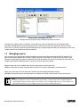
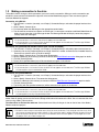
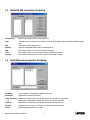
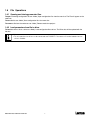
Over 100 years cumulative experience
24 hour rush turnaround / technical support service
Established in 1993
The leading independent repairer of servo motors and drives in North America.
Visit us on the web:
www.servo-repair.com
www.servorepair.ca
www.ferrocontrol.com
www.sandvikrepair.com
www.accuelectric.com
Scroll down to view your document!
For 24/7 repair services :
USA: 1 (888) 932 - 9183
Canada: 1 (905) 829 -2505
Emergency After hours: 1 (416) 624 0386
Servicing USA and Canada
MotionView94
Configuration and Programming Software
USER’S MANUAL
IM94MV01A
Table of Contents
1
MOTIONVIEW SOFTWARE . . . . . . . . . . . . . . . . . . . . . . . . . . . . . . . . . . . . . . . . . . . . . . . . . . . . . 2
1.1
1.2
1.3
1.4
1.5
1.6
2
Node tree and list views and how to change parameters. . . . . . . . . . . . . . . . . . . . . . . . . . . . . . . .
Managing projects . . . . . . . . . . . . . . . . . . . . . . . . . . . . . . . . . . . . . . . . . . . . . . . . . . . . . . . . . . . . .
Making a connection to the drive . . . . . . . . . . . . . . . . . . . . . . . . . . . . . . . . . . . . . . . . . . . . . . . . . .
Build RS-485 connection list dialog . . . . . . . . . . . . . . . . . . . . . . . . . . . . . . . . . . . . . . . . . . . . . . . .
Build Ethernet connection list dialog . . . . . . . . . . . . . . . . . . . . . . . . . . . . . . . . . . . . . . . . . . . . . . .
File Operations . . . . . . . . . . . . . . . . . . . . . . . . . . . . . . . . . . . . . . . . . . . . . . . . . . . . . . . . . . . . . . .
2
4
5
6
6
7
MOTIONVIEW TOOLS . . . . . . . . . . . . . . . . . . . . . . . . . . . . . . . . . . . . . . . . . . . . . . . . . . . . . . . . . 8
2.1
Oscilloscope tool . . . . . . . . . . . . . . . . . . . . . . . . . . . . . . . . . . . . . . . . . . . . . . . . . . . . . . . . . . . . . . 8
Safety Warnings
WARNING!
• Hazard of unexpected motor starting! When using the MotionView software, or otherwise
operating the SimpleServo Model 94 or 940 drive over RS-232/485 or Ethernet, the
motor may start unexpectedly, which may result in damage to equipment and/or injury to
personnel. Make sure the equipment is free to operate in this manner, and that all guards
and covers are in place to protect personnel.
• Hazard of electrical shock! Circuit potentials are at 115 VAC, 230 VAC or 480 VAC above
earth ground. Avoid direct contact with the printed circuit board or with circuit elements
to prevent the risk of serious injury or fatality. Disconnect incoming power and wait 60
seconds before servicing drive. Capacitors retain charge after power is removed.
• The symbol shown at left indicates additional information, shortcuts, or tips that do not
affect the safe operation of the drive.
MotionView User’s Manual: IM94MV01A
1
1
MotionView Software
MotionView is the setup and management tool for Lenze Model 94 and Model 940 servo products. It is similar to
Windows Explorer in the way information is arranged, logically divided into groups for viewing and editing.
This manual covers the concept and basic operations of the MotionView94 program, please refer to the corresponding
product’s User’s Manuals for details on these features and capabilities.
1.1
Node tree and list views and how to change parameters
The Motion View screen consists of 3 main panels: Node Tree, List View, and Message Window. Drives and Parameter
files appear in the Node Tree and have subsequent folders - parameter groups and different tools needed to work with
the Drive (Parameter file). Files and Drives appear almost identically in the Node Tree. You operate on both in the same
way. The main difference between them is that Drives can have a Connection but files cannot.
The Message Window gives information about communication status, supplies various information making troubleshooting
problems easier.
List View
Node Tree
Message
Window
Motion View Screen
To change any parameter, click on the parameter of interest on the list view. The dialog box opens and you can change
the value. There are several different kinds of dialogs for changing parameters:
•
•
•
Numeric value parameter entry dialog box.
Numeric value parameter entry with slider.
Selection type parameter dialog box (predefined values from which you can choose).
MotionView User’s Manual: IM94MV01A
2
All dialogs have a set of [Apply] [OK] and [Cancel] buttons. Use the [Apply] button to accept value changes but leave the
dialog open; Use the [OK] button to accept the changes and dismiss the dialog; Use [Cancel] to dismiss the dialog without
changes.
Some groups from the Node Tree have Action buttons in the list view. They will perform the action listed against the
buttons in the list view. (See picture below).
Numeric value parameter entry dialog box
Selection type parameter dialog box
Predefined values from which you may choose
Numeric value parameter entry with slider
MotionView User’s Manual: IM94MV01A
3
Action buttons embedded in list view
Example: clicking “Load fault history” loads the fault history from drive.
The right panel of Motion View is called the List View. When you click on a Node tree entry or subsequent folder,
parameters belonging to this group are displayed in the List View. You can see every parameter in detail; its current
value, units, min and max values of each parameter. When you navigate through the node tree, information in the list view
changes automatically to follow the node tree selection.
1.2
Managing projects
You can have many parameter files and drives opened at the same time. Information about which files and drives are
open and the current window layout is called a Project. A Project can be saved as a file to the PC’s hard drive. Future
sessions will allow opening a project to automatically load the desired files and drives into the node tree and restore the
windows layout. Note that MotionView will try to connect all drives listed in the project.
To save a project to a file use Motion View <Project | Save project> from the menu bar.
To start a new project and close all opened files and drives use <Project | New project> from the menu bar.
When you use this menu all drive connections and file will be closed. Node tree will be emptied.
To create a new project using an existing project as a template use <Project | Save project As> from the menu bar.
Note:
• A Project file doesnít save any Parameter files or drive data. It merely saves the list of opened devices
and windows positions on the screen. Use <Project | Save All configuration files> to save changes in all
opened files and drives, or use <Node | Save> to save each individual file or drive.
MotionView User’s Manual: IM94MV01A
4
1.3
Making a connection to the drive
To be able to view or change a driveís parameters you have to make a connection. When you make a connection you
establish a communication link between the physical drive and the MotionView program. There are several types of
interfaces MotionView supports.
Connection using RS-232:
1. The first time in a session (see note), use <Project | Connection Setup> and select the proper interface from
the list.
2. Select <Node | Connect drive>
3. For interfaces other then RS-232 go to the appropriate section below.
4. The drive will be connected and appear on the left tree. If a connection cannot be established MotionView will
display status information in the message window. The Message Window will display connection progress
and any other error messages.
Note:
• If the connection is successful, the drive will appear on the node tree.
• If the connection is unsuccessful then the drive will not appear on the node tree. The Message Window
will then explain why the connection failed.
Connection using multidrop RS-232/485 interface (PPP over RS-232/RS485):
1. The first time in a session (see note), use <Project | Connection Setup> and select proper interface from list.
2. Optionally click on the [Properties] button to change “COM Port” number and/or baud rate if needed. Note that
baud rate has to be the same as the drive settings.
3. Select <Node | Connect drive>. The Connection dialog opens.
4. Specify address(es) of the drive(s) you want to connect. See Build RS-485 connection dialog topic for details.
5. Click the [Connect] button.
6. Drive(s) with specified address(es) will be connected and appear in the left tree.
Note:
• If the connection is successful, the drive will appear on the node tree.
• If the connection is unsuccessful then the drive will not appear on the node tree. The Message Window
will then explain why the connection failed.
Connection using 10/100 Ethernet:
1. The first time in a session (see note), use <Project | Connection Setup> and select the proper interface from
the list.
2. Select <Node | Connect drive>. The connection dialog opens.
3. Specify IP address(es) of the drive(s) to connect to. See the Build Ethernet Connection List topic for details.
4. Click the [Connect] button.
5. The Drive(s) with the specified address(es) will be connected and appear on the left tree.
Note:
• If the connection is successful, the drive will appear on the node tree.
• If the connection is unsuccessful then the drive will not appear on the node tree. The Message Window
will then explain then why the connection failed.
To disconnect drive: Select the drive by clicking on its icon on the left tree. Use <Node | Disconnect> from menu bar.
Motion View will prompt you to save the current settings to file before it disconnects the drive. You can reconnect the drive
later by using <Node | Connect drive>.
To remove drive or file from the node tree: Select the drive or file by clicking on its icon on the left tree. Use <Node |
Remove node from project>.
Note:
• You don’t have to setup a connection every time you want to connect. Only once per session or any time
you want to change communication settings. If you saved your work in project file then you donít have to
go to Connection setup unless you want to use different communication options. Donít forget to re-save
the project file if you made changes to it.
MotionView User’s Manual: IM94MV01A
5
1.4
Build RS-485 connection list dialog
Connect One
Specifies one driveís address to be connected
Scan
Find and connect all drives on the network. A search will be performed for all drives in address range
0-31.
Add
Add address to the connection list.
Remove
Removes highlighted address from the connection list.
Now
This window shows a list of drives currently connected.
To be
This window shows a list of available drives that could be connected
Connect
Puts the drive selected in the “To be” window into the “Now” window.
1.5
Build Ethernet connection list dialog
IP address
You can specify a single device address in this field
Connected
Shows drives currently connected
To be connected
Shows drives Motion View found on the network and available for connection
- -> X
Used to remove highlighted addresses from the ìTo Be Connectedî list
Discover
MotionView will find every physically connected drive on the network
Connect
Connect every drive with an IP listed in the ìTo Be Connectedî list box.
Cancel
Dismiss dialog box without any action.
MotionView User’s Manual: IM94MV01A
6
1.6
File Operations
1.6.1 Opening and closing parameter files.
To open an existing configuration file use <Node | Open configuration file> from the menu bar. The File will appear on the
node tree.
To save the file use <Node | Save configuration file> from menu bar.
To remove a file from the node tree use <Node | Remove node from project>
1.6.2 Load parameters from file to drive.
To load data from a file to a drive use <Node | Load configuration file to drive>. The Drive data will be updated with the
file data.
Note:
• For this operation the drive must be connected and DISABLED. Parameters will not be loaded when the
drive is enabled.
MotionView User’s Manual: IM94MV01A
7
2
MotionView Tools
2.1
Oscilloscope tool
The Oscilloscope tool is a powerful, real-time display of your servo system’s characteristics. Like a “real” oscilloscope, the
Scope tool displays two channels simultaneously. Click on the RUN/STOP button to start or stop the scope display.
Signal Name
You can customize the information presented by the Scope tool by choosing the drop-down box in each channel. The set
of available signal depends on the drive model. Refer to the User’s Manual appropriate for your drive model to see the list
of the signals.
Scale
Scale sets the sensitivity of the display. Each division is considered one unit of the selected scale. A scale of 100 RPM/
div, for example, means that the signal will rise (or descend) by one division for every change of 100 RPM in the signal
level. Thus, a 500-RPM signal would deflect the signal by five divisions from the central reference line.
Offset
Offset sets the vertical distance from the central base line to the signal trace. This is useful if you want to compare two
signals. For example, if you wish to compare the actual vs. commanded motor velocity, you would enter an offset that
would move the two signals to the same side of the central reference line.
Time Base
Time base sets the number of cycles displayed per division. Higher frequencies have a shorter time base than lower
frequencies. If you wanted to display one cycle of a particular signal, your time base setting would therefore be lower for
high-frequency signals than for low-frequency signals.
Trigger/Trigger Level
Trigger level specifies the signal level after which the scope starts acquiring data. You can also specify which channel will
be a source for the trigger. The oscilloscope display will continue to run while the signal level crosses the specified level
(above if the trigger is set for rising or leading edge, or below if the trigger is set for trailing or falling edge).
Single
Also called one-shot trigger. If Single Sweep is selected, data acquisition will be stopped after the scope buffer is filled and
data displayed on the screen (frozen data). To repeat data acquisition, you will need to click the Single again.
MotionView User’s Manual: IM94MV01A
8
L
AC Technology Corporation • 630 Douglas Street • Uxbridge, MA 01569 • USA
+1 (508) 278-9100