1
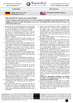
ZMU-3A
Instruction Manual
As of: July 2013
ALL ARTWORK, PICTURES AND TEXTS ARE COVERED BY OUR COPYRIGHT.
THEY MUST NOT BE COPIED FOR REPRODUCTION (E.G. ON CD-ROM DISKS OR INTERNET-SITES) OR USED IN THEIR ENTIRE FORM OR IN EXCERPTS WITHOUT OUR PREVIOUS WRITTEN AGREEMENT.
IF YOU ARE DOWNLOADING PDF-FILES FROM OUR INTERNET HOME-PAGE FOR YOUR PERSONAL USE, MAKE SURE TO CHECK FOR UPDATED VERSIONS.
WE CANNOT TAKE ANY LIABILITY WHATSOEVER FOR DOWNLOADED FILES, AS TECHNICAL DATA ARE SUBJECT TO CHANGE WITHOUT NOTICE.
Contents
1. Contents
1. Contents ............................................................ 2
2. Safety Instructions and Legal Disclaimer .... 4
2.1 Safety instructions ................................................... 4
2.2 Disclaimer ................................................................ 6
3. General Description ........................................ 9
6.1 Recall software version .......................................... 18
6.2 Selection of the Joystick pressure delay ........................ 18
6.3 Selection of the joystick response mode ....................... 19
6.4 Selection of motor torque tbd .................................... 19
6.5 Reset to factory defaults ............................................. 19
3.1 ARRI Order numbers ............................................... 12
7. Specifications ................................................ 20
4. Setup ......................................................................... 13
8. ARRI Service ................................................... 21
5. Operation of the ZMU-3A ......................... 13
5.1 Switching on ........................................................ 13
5.2 Calibration ............................................................. 14
5.3 Battery control ...................................................... 14
5.4 Zooming ................................................................ 15
5.5 Camera RUN ........................................................ 17
5.6 Video lenses ............................................................ 17
2
6. Special Functions Mode ............................. 18
This page is left intentionally blank
3
Safety instructions
2. Safety Instructions and Legal Disclaimer
2.1.
Safety instructions
General safety instructions
The ZMU-3A has been thoroughly tested
for quality of workmanship and operating
functions before leaving the factory.
Read and understand all safety and operating
instructions before you operate or install the
system.
To ensure optimal performance, it is essential
that you aquaint yourself with this instruction
manual and that you follow the operating
instructions described.
Retain all safety and operating instructions for
future reference.
Warning signs
Heed all warnings on the system and in the
safety and operating instructions before you
operate or install the system.Follow all installation and operating instructions.
Possible risk of injury or damage to equipment.
Do not use accessories or attachments not
recommended by ARRI, as they may cause
hazards and void the warranty.
This symbol indicates the risk of electric shock
or fire danger that could result in injury or
equipment damage.
Do not repair any part of the system. Repairs
must only be carried out by authorized ARRI repair
shops.
Do not remove any safety measure of the
system.
4
Do not place the system on an unstable cart,
stand, tripod, bracket, or table. The system
may fall, causing serious personal injury and
damage to the system or other objects.
Operate the system using only the type of
power source indicated in the manual.
Unplug the power cord by gripping the power
plug, not the cord.
Do not use solvents to clean.
Any violation of these safety instructions or the nonobservance of personal care could cause serious injuries
(including death) and damages on the system or other
objects.
Note:
Notes are used to indicate further informations
or informations from other instruction manuals.
image indicates objects which are shown in the illustration.
Safety instructions
Do not operate the system in high humidity
areas or expose it to water or moisture.
Product Identification
When ordering parts or accessories, or if any questions
should arise, please advise your type of product and
serial number.
5
Disclaimer
2.2
Disclaimer
Before using the products described in this manual be sure
to read and understand all respective instructions. The ARRI
Wireless Lens Control System is only available for commercial customers. The customer grants by utilization,
that the ARRI Zoom Control Unit (ZMU-3A) or other
components of the system are only deployed for commercial use. Otherwise the customer has the obligation to
contact ARRI preceding the utilization.
While ARRI endeavors to enhance the quality, reliability
and safety of their products, customers agree and acknowledge that the possibility of defects thereof cannot
be eliminated entirely. To minimize risks of damage to
property or injury (including death) to persons arising
from defects in the products, customers must incorporate sufficient safety measures in their work with the
system and have to heed the statuted canonic use.
No part of this document may be copied or reproduced in
any form or by any means without prior written consent
of ARRI. ARRI assumes no responsibility for any errors
that may appear in this document. The information is
subject to change without notice.
6
For actual design-in, refer to the latest publications of
ARRI data sheets or data books, etc., for the most up-todate specifications. Not all products and/or types are
available in every country. Please check with an ARRI sales
representative for availability and additional information.
ARRI or its subsidiaries does not assume any liability for
infringement of patents, copyrights or other intellectual
property rights of third parties by or arising from the
use of ARRI products or any other liability arising from
the use of such products. No license, express, implied
or otherwise, is granted under any patents, copyrights
or other intellectual property rights of ARRI or others.
ARRI or its subsidiaries expressly excludes any liability,
warranty, demand or other obligation for any claim,
representation, or cause, or action, or whatsoever, express
or implied, whether in contract or tort, including negligence, or incorporated in terms and conditions, whether
by statue, law or otherwise. In no event shall ARRI or its
subsidiaries be liable for or you have a remedy for
recovery of any special, direct, indirect, incidental, or
consequential damages, including but not limited to lost
profits, lost savings, lost revenues or economic loss of
ARRI is a registered trademark of Arnold & Richter Cine
Technik GmbH & Co Betriebs KG.
Disclaimer
any kind or for any claim by third party, downtime,
good-will, damage to or replacement of equipment or
property, any costs or recovering of any material or
goods associated with the assembly or use of our
products, or any other damages or injury of persons
and so on or under any other legal theory.
In the case one or all of the forgoing clauses are not
allowed by applicable law, the fullest extent permissible
clauses by applicable law are validated.
7
This page is left intentionally blank
8
The ZMU-3A is shaped like a classic handgrip
zoom controller and has the classic zoom knob that
assistants‘ thumbs all over the world are familiar with.
Main features
•
•
•
•
•
Classic shape zoom controller
for ARRI Wireless Remote System
Film and Video/HD compatible
Full speed lens motor drive even with
12volts video power supply
Full speed CLM-3 support
Flexible usage options:
- plugs directly into video lenses
- plugs directly into CLM motors
- plugs into UMC for wired use
- connects to WMU-3 for wireless use
Contrary to its classic exterior, under the hood it is
equipped with the latest technology. Zoom speed can be
precisely adjusted and zoom limits can be set. A large
bar graph shows the zoom ring position, the zoom
speed and various status messages, and a ZAP button
allows for a quick focus check. A switch changes the
running direction of the attached lens motor. Of course
the RUN switch can start film cameras, but the ZMU-3A
can also start/stop some high end video camcorders
and control the zoom motor on various video lenses.
If only zoom is required, the ZMU-3A can be connected
with a cable directly to an ARRI CLM-1, CLM-2 or CLM-3
lens motor and to the camera. If focus and/or iris are
also to be used, the ZMU-3A can become part of the
cabled ARRI Lens Control System (LCS) or of the ARRI
Wireless Remote System (WRS) by being connected to
a Universal Motor Controller UMC-1, Universal Motor
Controller UMC-3, Lens Data Box or FEM-2.
For wireless use, the ZMU-3A becomes part of the ARRI
Wireless Remote System. Via the Wireless Zoom Bracket
WZB-3 it attaches to the Wireless Main Unit WMU-3.
The special shape of this bracket allows the assistant to
position the ZMU-3A in relation to the WMU-3 to suit
his/her personal preference.
The ZMU-3A finally allows an ARRI LCS and WRS
compatible zoom controller to be attached to the tripod
handle. This can be done either using the ZMU-3 Pan
Handle (K2.65006.0) or with the rosette on the right
side of the ZMU-3A (M6 thread).
General Description
3. General Description
9
General Description
Wireless Zoom
Bracket (WZB-3)
rosette-mount
socket
CAL-button
RESET-botton
SET-button
ZAP-button
speed limit
control
message display
camera-RUN
button
zoom knob
zoom-position
display
marker
area
speed limit display
(001…100)
lens motor
10
ARRI Order Numbers
K2.65036.0
Cable ZMU-3 - WRS (0,3m/1ft) KC 105-S
Connects ZMU-3(A) to WMU-3
K2.65226.0 CLM-2/3 motor control via ZMU-3(A) (1m / 3ft)
Power supply through ARRI PSC* system connector
Camera Run function with 235, all 435, 535, 16SRIII, ARRICAM
replaces KC 91-S and KC 117-S in combination with the
appropriate PSC* power supply cable
K2.65017.0
Wireless Zoom Bracket WZB-3
for mounting the ZMU-3(A) to WMU-3
K2.65132.0
ZMU-3(A) Zoom Bracket assy. for WCU-3
for mounting the ZMU-3(A) to WCU-3
K2.65237.0 Cable ZMU-3 -RED-PSC* (0,6m/2ft)
Power supply through ARRI PSC* system connector
Camera REC function
connects ZMU-3(A) to RED camera
K2.65006.0
ZMU-3 Pan Handle
cradle to attach the ZMU-3(A) to tripod pan
handle (18mm diameter or smaller)
K2.65108.0
ZMU-3 Pan Handle
cradle to attach the ZMU-3(A) to tripod pan
handle (20mm diameter)
K2.65003.A Zoom Main Unit
ZMU-3A
K2.65159.0 Cable ZMU-3 - LCS (0,25m/0.8ft) KC 129-S
connects ZMU-3(A) to LCS - Bus (WCU-3)
K2.65009.0 Cable ZMU-3 - LCS (0,8m/2.6ft) KC 92-S
connects ZMU-3(A) to LCS - Bus
K2.65010.0 Cable ZMU-3 - LCS (10m/33ft) KC 93-S
connects ZMU-3(A) to LCS - Bus
K2.65059.0 Cable ZMU-3 - LCS (30m/100ft) KC 112-S
connects ZMU-3(A) to LCS - Bus
* PSC power supply cables
Order no.
Description Lenght
K2.65206.0 PSC-XLR3 1,5m/5ft
K2.65207.0 PSC-XLR4 1,5m/5ft
K2.65208.0 PSC-DTAP 0,6m/2ft
K2.65209.0 PSC-HI12 0,6m/2ft
K2.65210.0 PSC-FI11 0,6m/2ft
K2.65211.0 PSC-RS
0,6m/2ft
K2.65212.0 PSC-FI2 1,5m/5ft
K2.65213.0 PSC-LCS 0,6m/2ft
connects to
24volts battery
12volts battery
Anton Bauer D-Tap socket
Hirose 12pin socket
ARRIFLEX 435, SONY F23/F35
ARRI RS socket
ARRI OBB-2 battery
ARRI LCS bus
General Description
3.1
Function
Power supply only
Power supply only
Power supply only
Power supply + RUN
Power supply only
Power supply + R/S
Power supply only
Power supply + CAN
11
Setup
4. Setup
Prior to the operation of the ZMU-3A, make sure that
- the support rods are securely fastened to the camera,
- the motor units are securely fastened to the support rods
- and the motor drive gear engages the lens gear ring
with as little play as possible.
LCS Bus:
Use cables KC 92-S (0,8m), KC 93-S (10m) or KC 112-S
for the connection between ZMU-3 and LCS bus devices
like CLM-1, UMC-1, UMC-3, ARRICAM Lens Data
Boxes LT/ST or 435 FEM-2. Power will be provided
through the LCS-bus.
The ARRIFLEX 435 Advanced/Xtreme must not be
connected with the following cables:
LC-S1, LC-S2, LC-A1, LC-A2, LC-A3, LC-C1, LC-C2
12
CLM-2/-3 Motors:
Use K2.65226.0 ZMU-3 CLM PSC cable and the appropriate PSC power cable for the connection between
ZMU-3A and a CLM-2 or CLM-3. The power will be
supplied through selected power source.
When using the CLM-3 lens motor, set the torque
suitable for the kind of lens used.
Refer to chapter 6.4 for details
Use KC 105-S for the connection between ZMU-3A and
a WMU-3 Wireless System. The WZB-3 bracket enables
ergonomic mount of the ZMU-3A in this application.
Note:
WCU-3:
Use KC 129-S for the connection between ZMU-3A and
a WCU-3 Wireless Control Unit. The WCU-3 bracket
K2.65132.0 enables ergonomic mount of the ZMU-3A in
this application.
Setup
WMU-3:
WMU-3 Software version 1.02 or above is necessary
for wireless operation of the ZMU-3A with all display
functions.
ZMU-3A WMU-3 setup example, using KC105-S and WZB-3
ZMU-3A WCU-3 setup example, using KC129-S and WCU-3 bracket
13
This page is left intentionally blank
14
5.1
Switching on
The ZMU-3A has no dedicated power-switch.
Power-on the ZMU-3A using the power switch of the
connected supply source (Camera/UMC/WMU-3) or
connect the appropriate ZMU-3A cable to the unit.
After connecting to the RS/LCS socket three lines briefly
flash up in the speed display (D image A).
The zooming speed previously used is then shown on
the display. The status display indicates ready with the
rdy display (D image B).
In case a zoom range was previousely stored this is now
shown on the marking display (D image C).
• The lens motors must be calibrated in case this had
not been done before, or the lens settings have been
changed while switched off. Press the LENS CALbutton on the ZMU-3A D image to calibrate the
end-stops.
• Select the desired drive direction with the drive
direction switch on the ZMU-3A D image.
Note:
A
B
Operation of the ZMU-3
5. Operation of the ZMU-3A
If operated together with a FEM-2/UMC/LDB the
drive direction can also be changed on these units.
C
15
Operation of the ZMU-3
5.2
Calibration
The end stops of the zoom ring are defined and stored
during the automated calibration process in order to
prevent driving the lens ring up against the lens' end
stops. Previously set values are thereby erased.
Calibration must be carried out
- during initial set-up,
- after a lens change,
- after the lens ring has been manually moved
while the units were disconnected from the power,
e.g. after an extended break
- after the motor drive gear has been removed from the
lens control ring.
C
5.3
D
E
Battery control (BAT)
An illuminated or flashing bat symbol on the status
display of the ZMU-3A indicates that the battery must
be exchanged or recharged (D image E).
• Press the LENS CAL -button D image on the
ZMU-3A to start the calibration process.
Do not begin any new takes!
During calibration the cal-symbol is illuminated on the
display (D image C).
The bat sign signals the following voltage levels:
The cal symbol flashes:
Lens end stops are not yet defined, or the lens
has been moved while the LCS was switched
off and then driven against the end-stops.
Recalibrate! (D image D)
16
Operating mode
bat Symbol
Voltage
24V
illuminated
<21V
12V
illuminated
<10V
7.2V (wireless)
illuminated
<6.8V
flashes
<6.3V
zoom lever
• Press the zoom lever D image in the desired direction.
The focal length will be altered. The greater the
force, the faster the zoom will react.
5.4.1
ZAP-key
Zooming
Setting zoom speed
The sensitivity of the zoom lever (zoom speed) can be
adjusted and is indicated on the speed display of the
ZMU-3A. The smaller the value the lower the maximum
zoom speed will be.
+ / - key
• The + and - buttons on the ZMU-3A are used to set
the zoom speed. Pressing the + or - button briefly
will change the speed setting in increments of 1,
pressing the buttons longer will alter the speed in
increments of 10. The zooming speed can be set
within a range of 1 and 100 (D image G, H).
H
Note:
5.4.2
Operation of the ZMU-3
5.4
Various modes of joystick responding behaviour are
available. Please see section 6.3 and 6.4 for details.
ZAP-function
• The ZAP button D image switches to maximum
zoom speed – independently of the speed setting.
The display indicates ZAP.
17
Operation of the ZMU-3
5.4.3
SET-button
J
RESET-button
K
L
M
Defining the zoom range
For zooming, a defined range can be selected and
stored.
• Drive the zoom to one end of the selected range.
• Press the SET-button D image and keep it held
down. The LENS and ANGLE symbols are flashing
(D image J).
• Drive the zoom to the other end of your selected
range and release the SET-button. The LENS and
ANGLE symbol will now be illuminated. The zooming range is indicated on the marker display
(D image K).
• When one end stop is reached (zooming lever not
pressed) the complete bar of the marker display
flashes towards the end of the reached range
(D image L).
• If one of the defined end stops is reached while
zooming (zooming lever is pressed), the LENS and
ANGLE symbol and the position marker will be
flashing (D image M).
5.4.4
Erasing the zoom range
• Press the RESET-key D image and hold it briefly.
The LENS and ANGLE symbols will disappear.
18
Camera RUN
The camera can be started with the camera RUN
switch. This switch has three positions:
RUN-switch
–
–
–
middle OFF
intermediate switching ON
permanent switching ON
24V ARRI cameras are started with the intermediate
switching on function. In camera RUN this is indicated
on the status display of the ZMU-3A.
Note:
5.6
N
The permanent switch-on function is available on
the ZMU-3A socket. Please contact your ARRI
Service Center for details.
Video lenses
Operation of the ZMU-3
5.5
The ZMU-3A can be connected to video lenses with the
cable KC-107 (K2.65041.0).
In this mode the marker display indicates the zooming
speed starting from the middle position.
19
Special Functions Mode
20
6. Special Functions Mode
6.1
Recall software version
• off
• 1-6
…
…
delay off
delay 1 (short) … 6 (long)
Hold the SET and RESET buttons depressed while
powering the ZMU-3, until all display segments light
up. Then release the keys and press RESET once. In the
bargraph display one bar will be displayed.
The speed limit display then shows SW, Version # prefix
(e.g. 01_ ) and Version # suffix (e.g. 100 ) sequentially.
The value will be saved when pressing the SET button. The
successful execution will be confirmed by rdy displayed. The
ZMU-3 will remember this setting even when powered down.
Note:
Display value rdy shows the actually saved
smoothing value.
Note:
6.3
Selection of the Joystick response mode
6.2
After entering the Special Functions Mode it is
possible to step through the different functions by
repeatedly pressing the RESET button. To leave the
Special Functions Mode, disconnect the unit.
Selection of the joystick pressure delay
Hold the SET and RESET buttons depressed while
powering the ZMU-3 until all display segments light up.
Then release the buttons and press RESET repeatedly,
until three bars will be displayed in the bargraph
display.
The ZMU-3 provides several steps of joystick response
delay selectable by the + and - keys.
This delay smoothes the joystick pressure in respect to
the rise in motor speed.
Hold the SET and RESET buttons depressed while
powering the ZMU-3, until all display segments light up.
Then release the buttons and press RESET repeatedly,
until four bars will be displayed in the bargraph display.
The ZMU-3 provides four response modes selectable by
the + and - buttons.
• HYP …
hyperbolic
• Ln …
logarithmic
• PAr …
parabolic
• Lin …
linear
In the picture left the correlation between the joystick
pressure and the motor speed is shown.
The selected mode will be saved when pressing the SET
y-axis: motor speed
1 ...
4 ...
As the CLM-3 lensmotor is VERY strong, adequate
torque adjustement is adviseable, especially to
prevent accidental damage to more delicate lenses
x-axis: joystick pressure
button. The successful execution will be confirmed by
rdy displayed. The ZMU-3 will remember this setting
even when powered down..
Note:
6.4
lowest e.g. for video lenses
highest e.g. for heavy movie zoom lenses at low
ambient temperatures and/or fastest zoom speed
Display value rdy shows the active saved mode.
Lens Motor Torque setting (CLM-3 only)
Hold the SET and RESET buttons depressed while
powering the ZMU-3A, until all display segments light
up. Then release the buttons and press RESET repeatedly,
until five bars will be displayed in the bargraph display.
Note:
6.5
The torque setting menu will be displayed only in
conjunction with a connected CLM-3 lens motor.
Special Functions Mode
The ZMU-3A provides four torque settings for the CLM-3
selectable by the + and - buttons.
Reset to factory defaults
Hold the LENS CAL and RESET buttons depressed while
powering the ZMU-3. The display will show dEF. Then
release the buttons. After a short delay the ZMU-3 resets
automatically to its default values:
Joystick response mode
Joystick pressure delay
HYP
2
21
Specifications
7. Specifications
Operating temperature
-20 to +50 °C ( -4 to +122°F )
Operating voltage
10 to 30 V DC
ARRICAM compatible
WCU-3/WMU-3 compatible
Typ. current consumption without lensmotor
0,05A (24V) / 0,07A (12V)
Dimensions ( h * w * d ) w/o (with) connector
178 * 66 * 37 mm
3.8 * 2.6(3.3) * 8.8 in
Weight 400 g ( 5 oz )
Information to the user:
Class A Statement:
Note: This equipment has been tested and found to comply with the limits for
a Class A digital device, pursuant to Part 15 of the FCC Rules. These limits are
designed to provide reasonable protection against harmful interference when
the equipment is operated in a commercial environment. This equipment generates, uses, and can radiate radio frequency energy and, if not installed and used
in accordance with the instruction manual, may cause harmful interference to
radio communications. Operation of this equipment in a residential area is likely
to cause harmful interference in which case the user will be required to correct
the interference at his own expense.
22
23
ARRI Service
technical data are subject to change without notice
© ARRI 2013
ZMU-3A User Manual
ARRI Order no. K5.65998.A
ARNOLD & RICHTER CINE TECHNIK Türkenstr. 89 D-80799 München
Phone +49 (0)89 - 3809-0 Fax +49 (0)89 - 3809-1244
www.arri.com