1
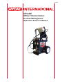
L-4231 OFS-AM Offline Filtration Station for Asset Management Operation & Service Manual L-4231 | Created 9.2013 - TABLE OF CONTENTS 1. Introduction ...............................................................................................................................................................................4 2. Warnings / Cautions & Notes ...................................................................................................................................................5 2.1 Technical Assistance ............................................................................................................................................................ 6 2.2 Obligations and Liability ....................................................................................................................................................... 7 2.3 Acronym List ......................................................................................................................................................................... 7 3. Specifications ............................................................................................................................................................................ 3.1 Appropriate Use .................................................................................................................................................................... 3.2 Fluid Compatibility ............................................................................................................................................................... 8 8 9 4. General Operations ................................................................................................................................................................10 4.1 External Panel Components ................................................................................................................................................. 10 4.2.1 System Features ............................................................................................................................................................ 11 5. Cleaning Methods ................................................................................................................................................. 5.1 Filtration Technique ............................................................................................................................................................... 13 13 6. Operating Instructions ...............................................................................................................................................................14 6.1 External Panel Components ................................................................................................................................................. 14 6.2 Operator Interface Controls .................................................................................................................................................. 14 6.2.1 Flushware Start-Up Screen ............................................................................................................................................ 14 6.2.2 Service Tools Screen ...................................................................................................................................................... 15 6.2.3 User Input Screen ........................................................................................................................................................... 15 6.2.4 Live Test Data Screen ..................................................................................................................................................... 16 6.2.5 Historical Report Screen ................................................................................................................................................. 17 6.2.6 Time Zone Configuration Screen .................................................................................................................................... 17 6.2.7 Shut Down Procedure .................................................................................................................................................... 17 7. Maintenance Instructions .........................................................................................................................................................18 7.1 Servicing Filter Elements…………...........................................................................................….......................................... 18 7.2 AC Motors ............................................................................................................................................................................ 20 7.3 Inspection & Maintenance Schedule ................................................................................................................................... 20 8. Spare Components ...................................................................................................................................................................20 8.1 Sensor Verification ............................................................................................................................................................... 21 8.2 Taking Fluid Samples ........................................................................................................................................................... 21 8.3 Recalibration / Service Procedure ....................................................................................................................................... 21 9. CS1000 Technical Data …………...........................................................................................…................................................ 22 10. AquaSensor (AS1000) .............................................................................................................................................................23 10.1 AS1000 Technical Data ........................................................................................................................................................ 24 11. Warranty .................................................................................................................................................................................... 11.1 Service ................................................................................................................................................................................ 25 25 Appendices Appendix A: Cleanliness Classes - Brief Overview ..................................................................................................................... A.1 ISO 4406:1999 ..................................................................................................................................................................... A.2 SAE AS 4059 ....................................................................................................................................................................... A.3 NAS 1638 ............................................................................................................................................................................. 26 28 29 30 Appendix B: Mechanical Drawings ……………………….………………........................................................................……….....31 B.1 Sales Drawing ……………………….………………........................................................................……….........…............... 31 B.2 Parts List Drawing ...…….……………….................................................................................…………............................... 32 B.3 Hydraulic Schematic ...…….……………….................................................................................…………............................ 33 Appendix C: Electrical Schematic ...…….……………….................................................................................…………................ 34 L-4230 OFS-AM User Manual 1. Introduction HYDAC’ patent pending Offline Filtration Station for Assest Management (OFS-AM) is the first of its kind on the market. The cart is designed to filtering particulate and free water contamination, while monitoring ISO cleanliness with user-defined, automatic features. The OFS-AM is equipped with an industrial strength touch screen computer and custom software that runs and records the fluid ISO cleanliness condition. Each run generates its own specific report (in Excel) that tracks the fluid condition and provides real time data. The management of your equipment’s health can be logged and recorded maintaining a continuous record of your equipment while cleaning the fluid at the same time. Once a machine asset number or name is entered the OFS-AM filters the fluid to the selected ISO cleanliness and shuts down automatically. The onboard screen provides a graphical display indicating the progress of the cleaning of the fluid as well as the desired target cleanliness level. Each subsequent time that specific machine is connected the PC will expand the existing report thereby providing a complete history of the fluid conditions in one location that can be used for trending analysis. In auto mode, the system will run until the cleanliness Target codes are reached. Upon reaching the codes, the pump will stop and the cycle complete will display on the screen. When in manual mode, the system will run continuously and display the ISO codes. Both modes will generate a formatted report summarizing data captured during the cycle. The OFS-AM is designed to transfer fluid through two (2) filters in series for staged particulate or water/particulate removal. Both filters are top-loading and include element indicators in the cap. The water sensor is available for providing the water saturation of the fluid, which can be displayed on the control panel. Dissolved water content of the oil is displayed as percent of saturation. The cart is an oil filtering system that captures contaminant particles using a high performance filter. The cart also includes a second water removal filter element that can be used instead of the standard filter to remove free water. Precautions The cart represents the latest in technology and safety. The OFS-AM can, however, constitute a hazard if used incorrectly by untrained personnel or if not used as specified. This may result in: ■ potential injury ■ damage to the machine and/or other equipment of the client’s All safety procedures associated with the operation of electrical powered equipment must be observed. Position the machine on a level surface, away from ignition sources, and in an orientation where the disconnect switch is readily accessible. Features ■ ■ ■ ■ ■ ■ ■ ■ Real time monitoring of ISO cleanliness classes Automatic shutdown when user defined ISO codes are reached USB port allows the ISO code data to be downloaded for further processing and/or printing 30 mesh suction strainer and 230 micron filter included to protect the particle monitor from clogging Water sensor allows real-time water saturation of the fluid to be displayed Bypass valve allows cart to be used as a transfer cart Single lift point Plastic removable drip pan 4 En © 12.2012 HYDAC User Manual OFS-AM L-4230 2. Warnings, Cautions And Notes Explanation of Symbols and Warnings This is the safety alert symbol. When you see this symbol on your machine or in this manual, be alert for the potential of personal injury. Follow the precautions and safe operating practices highlighted by this symbol. A signal word — DANGER, WARNING, or CAUTION — used with the safety alert symbol. DANGER identifies the most serious hazards. General precautions are on CAUTION labels. Follow Safety Instructions Read the safety messages in this manual and on the machine. Follow these warnings and instructions carefully. Review them frequently. Be sure all operators of this machine understand every safety message. Replace safety labels immediately if missing or damaged. Operate Only If Qualified Do not operate this machine unless you have read the operator’s manual carefully and you have been qualified by supervised training and instruction. Familiarize yourself with the job site and your surroundings before operating. Inspect Machine Inspect the equipment carefully before each use. Keep all parts in good condition and properly installed. Fix damage and replace worn or broken parts immediately. Pay special attention to hydraulic hoses and electrical power cord. Handle Fluids Safely—Avoid Fires Filtering of fuel or other flammable liquids is not recommended. Store flammable fluids away from fire hazards. Do not incinerate or puncture pressurized containers. Make sure machine is clean of trash, grease, and debris. Do not store oily rags; they can ignite and burn spontaneously. Prepare for Emergencies Be prepared if a fire starts. Keep a first aid kit and fire extinguisher handy. Keep emergency numbers for doctors, ambulance service, hospital, and fire department near your telephone. Practice Safe Maintenance Understand service procedure before doing work. Work areas should be level, clean, and dry. Before servicing machine: ■ Position the machine on a level surface ■ Allow to cool if hot Keep all parts in good condition and properly installed. Fix damaged components immediately. Replace worn or broken parts. Remove any buildup of grease, oil, or debris Handle Chemical Products Safely Direct exposure to hazardous chemicals can cause serious injury. Potentially hazardous chemicals used with equipment include such items as lubricants, coolants, paints, and adhesives. A Material Safety Data Sheet (MSDS) provides specific details on chemical products: physical and health hazards, safety procedures, and emergency response techniques. Check the MSDS before you start any job using a hazardous chemical. That way you will know exactly what the risks are and how to do the job safely. Then follow procedures and recommended equipment. (Contact HYDAC prior to using with fluids other than hydraulic fluids). Burn Hazards Do not touch Allow to cool before servicing Wear Protective Clothing Wear close fitting clothing and safety equipment appropriate to the job. Operating equipment safely requires the full attention of the operator. Do not wear radio or music headphones while operating the machine. Service Machines Safely Tie long hair behind your head. Do not wear a necktie, scarf, loose clothing, or necklace when you work near machine tools or moving parts. If these items were to get caught, severe injury could result. Remove rings and other jewelry to prevent electrical shorts and entanglement in moving parts. © 12.2012 HYDACEn 5 L-4230 OFS-AM User Manual Illuminate Work Area Safely Illuminate your work area adequately but safely. Use a portable safety light for working inside or under the machine. Make sure the bulb is enclosed by a wire cage. The hot filament of an accidentally broken bulb can ignite spilled fuel or oil. Work In Clean Area Before starting a job: ■ Clean work area and machine ■ Make sure you have all necessary tools to do your job. ■ Have the right parts on hand. ■ Read all instructions thoroughly; do not attempt shortcuts. Use Proper Tools Use tools appropriate to the work. Makeshift tools and procedures can create safety hazards. For loosening and tightening hardware, use the correct size tools. DO NOT use U.S. measurement tools on metric fasteners. Avoid bodily injury caused by slipping wrenches. Dispose of Waste Properly Improperly disposing of waste can threaten the environment and ecology. Potentially harmful waste includes such items as oil, fuel, coolant, brake fluid, filters, and batteries. Use leak-proof containers when draining fluids. Do not use food or beverage containers that may mislead someone into drinking from them. Do not pour waste onto the ground, down a drain, or into any water source. Electrical Hazards ■ All work on the electrical equipment must be carried out by a qualified electrical equipment must be carried out by a qualified electrician. ■ The electrical parts of the cart must be regularly checked. ■ Any loose contacts must be rectified immediately. ■ The control box must always be secured. It may be accessed only by authorized staff. ■ If work needs to be performed on electrically live parts, a second person must be called in to turn off the main switch, if necessary. ■ Voltage or current hazard sufficient to cause shock, burn, or death. ■ Remove power before servicing. ELECTRICAL WARNING: The system’s 1 ½ HP electric motor draws 15 amps at 115 volts ± 10%, 60 Hz at full load. Starting current could be approximately 4 to 8 times greater. A proper circuit breaker should be installed to protect the motor and meet national and local electric codes. Recommended size for an extension cable is 12AWG - 3 conductor with a maximum length of 25 feet. WARNING DENOTES SITUATIONS WHICH CAN LEAD TO MORTAL INJURY IF SAFETY PRECAUTIONS ARE NOT OBSERVED. 2.1 Technical Assistance For Technical Assistance please call 1-610-266-0100 or email http://www.hydacusa.com/techsupport/askus.cfm 6 En © 12.2012 HYDAC User Manual OFS-AM L-4230 2.2 Obligations and Liability Using the Documentation Note that the method described for locating specific information does not release you from your responsibility of carefully reading these instructions prior to starting the unit up for the first time and at regular intervals in the future. What do I want to know? I determine which topic I am looking for. Where can I find the information I’m looking for? The documentation has a table of contents at the beginning. There, I select the chapter I’m looking for, along with the corresponding page number. The document number with its edition date enables you to order another copy of the operating and maintenance instructions. The index is incremented every time the manual is revised or changed. Document Number tel Produkt / Kapi HYDAC Filtertechnik GmbH BeWa 123456a de Edition Date de Seite x Page Number 200x-xx-xx Document Language While every precaution has been taken to ensure accuracy and completeness in this literature, HYDAC assumes no responsibility, and disclaims all liability for damages resulting from use of this information or for any errors or omissions. 2.3 Acronym List CS: CS 1000 Contamination Monitor VAC: Voltage Alternating Current AS: AquaSensor 1000 VDC: Voltage Direct Current DHC: Dirt Holding Capacity POT: Potentiometer GPM: Gallons Per Minute NPT: National Pipe Thread VFD: Variable Frequency Drive ORB: O-Ring Boss © 12.2012 HYDACEn 7 L-4230 OFS-AM User Manual 3. Specifications Design Parameters Process Fluid Type: Hydraulic and lubricating oils Seal Compatibility: Viton seals: compatible with most mineral based oils. Inlet Fluid Temperature: -20°F - 150°F (-29°C - 65°C); Fluid Viscosity Dependent. Inlet Pressure: 15 PSIG (1.0 bar) (a positive inlet pressure may damage pump shaft seals and cause fluid loss) Fluid Circulation Rate: 5 GPM Operating Viscosity: 1000 SUS (230 cSt) MAX Electrical Power Requirements: 120 VAC, 1 Phase, 60 Hz, 15 Amp Weight: 195 lbs. (88 kg) Dimensions: 26.6 inch x 25.25 inch x 45 inch (675.6 mm x 641.4 mm x 1143 mm) Operating Temperature (Electronics): 41°F to 104°F (5°C to 40°C); Up to 95% non-condensing humidity External Components Hose Connections: Discharge: 10' x 75" diameter hose with .38 female half aeroquip QD coupling model FD45-1003-06-06 Suction: 10’ x 1.00” diameter hose with 1.00 female half aeroquip QD coupling model FD45-1003-16-16 Electrical Control Box: NEMA 4 Enclosure containing an industrial strength touch screen computer and custom software; displaying the particle counts, and water sensor percent saturation. Customer Connections: USB and VGA Ports. Motor: 1.5HP; IP54; Altitude up to 3300 FT (1000 m); Max relative humidity 80% for temperatures up to 88°F (31°C); Pollution Degree 2 Pump: External gear pump Wheels: 15.6 inch (25.4 cm) pneumatic wheels Added Value Particle Filter: High Efficiency 10 mm Element Filtration Ratio wrt ISO 16889: ß4.8 (c) ≥ 200 ß6.3 (c) ≥ 1000 Dirt Holding Capacity: 238 gm (8.4 oz) Water Removal Filter: 22 oz. (651 mL) free water capacity Particle Counter: Laser particle monitor for measuring particle contamination; reports data (in 90 second intervals) as ISO 4406:1999 cleanliness code. Download results to a PC via USB connection. Water Sensor: Monitors dissolved water content in system fluid and displays measurement as percent of fluid saturation. 3.1 Appropriate Use The OFS-AM is designed exclusively for the filtration of non-hazardous fluids, provided their temperature does not exceed the boiling point at atmospheric pressure. ■ The boiling point at atmospheric pressure of fluids to be filtered must be higher than the maximum permissible working temperature of the caddy. ■ The maximum working temperature, the maximum working pressure and the maximum pressure must not be exceeded. ■ The cart must not be used to filter substances which will corrode the materials used. ■ Any other use is regarded as inappropriate. HYDAC is not liable for any damage resulting from such use. ■ Appropriate use also demands compliance with all instructions in the operating manual, and ensuring that all maintenance and service work is correctly performed. 8 En © 12.2012 HYDAC User Manual OFS-AM L-4230 3.2 Fluid Compatibility Any petroleum based fluid which is capable of being counted using a laser particle sensor. The fluid must be fully homogeneous and translucent. Emulsions, micro emulsions, or certain fluids with additives that can give false particle readings, for example Mobil Fluid 424, is not recommended. Appropriate seals should be chosen by the user to ensure compatibility. WARNING! PERFORMANCE OF THE OFS-AM IS BASED UPON THE USE OF FILTER ELEMENTS. THE OFS-AM IS DESIGNED AROUND THE PRESSURE DROPS AND SPECIFICATIONS OF HYDAC Betamicron Media. Cleaning after switching fluids - Cross contamination flushing STEP 1 - Prepare an empty waste oil container (5 gallon bucket), as well as a top-off container for fluid removed from the hydraulic system (5 gallons). STEP 2 - Insert suction wand into reservoir and place return wand into the waste container. STEP 3 - Replace existing particle filter and water removal filter with those of the fluid in the machine (if Filtration Station has Hy-Gard filters and machine uses Plus-50, then install filters used with Plus-50 oil). STEP 4 - Run the Filtration Station until the waste container is filled with about 4 gallons of fluid. STEP 5 - Remove return wand from waste container, wipe it clean, and insert into reservoir. STEP 6 - Position wands in the correct orientation and begin reservoir filtration until desired cleanliness level has been achieved. STEP 7 - Cycle machine hydraulic functions. STEP 8 - Resume reservoir filtration. Sensor Verification For cleanliness/sensor verification, it is recommended that the user correlate readings from the Filtration Station with bottle samples sent to independent laboratories. The laboratory must provide particle concentration information per the ISO 4406:1999, 11943 and 11171 requirements for optical particle counters. Taking Fluid Sample STEP 1 - To initiate the sampling process, locate the filter housing bleed valve on the filter cap of the inlet filter. STEP 2 - Pass a minimum of 200 mL of fluid through the filter bleed valve into a waste container before collecting the fluid. STEP 3 - Place the sampling bottle in position to collect the fluid. Use a sampling bottle having a contaminant level of at least 2 decades lower than the expected sample as qualified per the American National Standard Procedure for Qualifying and Controlling Cleaning Methods for Hydraulic Fluid Power Sample Containers, ANSI/B93.20-1972, ISO 3722-1976). STEP 4 - After removing the cap from the sample bottle, place the bottle under the stream of fluid. Do not allow the sample hose to touch the inside of the bottle. STEP 5 - Take a sample of at least 50-90% of the sampling bottle volume. STEP 6 - To terminate the sampling process, remove the bottle from the fluid stream. STEP 7 - Recap the sample bottle immediately after filling. © 12.2012 HYDACEn 9 L-4230 OFS-AM User Manual 4. General Operations The SSC is designed to remove particulate and free water contamination, as well as monitor the oil contaminant levels in the fluid. Fluid contamination is displayed as an ISO 4406 Cleanliness Code using a laser-based sensor and light blocking technology. Dissolved water content of the oil is displayed as percent of saturation. The SSC is an oil filtering system that captures contaminant particles using a high performance filter. The SSC also includes a second water removal filter element that can be used instead of the standard filter to remove free water. The SSC represents the latest in technology and safety. The SSC can, however, constitute a hazard if used incorrectly by untrained personnel or if not used as specified. This may result in: ■ potential injury ■ damage to the machine and other equipment of the client Below are summarized instructions for operation the SSC. ■ All safety procedures associated with the operation of the electrical powered equipment must be observed Position the machine on a level surface, away form ignition sources, and in an orientation where the E-Stop push button is readily accessible. Ensure the E-Stop is disengaged (pulled out). ■ Place the suction (1”) hose into the fluid to be filtered or transferred. Place the discharge (3/4”) hose into the machinery reservoir or waste container depending on desired operation. Ensure that the wands are secured to avoid possible fluid loss. ELECTRICAL WARNING The system’s 1 ½ HP electric motor draws 15 amps at 115 volts ± 10%, 60 Hz at full load. Starting current could be approximately 4 to 8 times greater. A proper circuit breaker should be installed to protect the motor and meet national and local electric codes. Recommended size for an extension cable is 12AWG - 3 conductor with a maximum length of 25 feet. ■ To energize the unit, connect to an appropriately grounded 115 VAC, 60 Hz single phase, 15 amp electrical receptacle. Ensure the power switch is in the “ON” position. The touch panel will indicate that the unit is energized and load the flushware program automatically. ■ To start the unit, refer to Section 4.2, “Operator Interface Controls.” ■ T o power-down the unit, ensure the motor is off or the test is completed and then enter the “SERVICE TOOLS SCREEN” (Section 4.2.2). Press the “CONFIGURATION” button to proceed to the “TIME ZONE CONFIGURATION SCREEN” (Section 4.2.6). Press the “Shutdown Windows” button and wait for the interface to black-out. Then place the power switch in the “OFF” position and finally unplug the unit. Refer to section 4.2.7 for entire shut down procedure. 4.1 External Panel Components 1. Operator Interface: Touch panel, with software to control the pump and sensors. 2. Emergency Stop: PUSH to employ the hard-stop PULL to release the E-Stop 3. USB Bulkhead: USB Communications Port; connected to the Operator Interface. Used for exporting data, or connecting external input device (Keyboard, Mouse, etc.) 4. VGA Bulkhead: Video Graphics Array Port; connected to the Operator Interface. Used to connect an external monitor that uses a 15-pin plug and socket. 5. Power Switch: ON / OFF; 20Amp; 2-Pole Circuit Breaker. 10En © 12.2012 HYDAC User Manual OFS-AM L-4230 4.2.1 System Features Control/Indicator Description Particulate Filter Indicator The HYDAC D5 visual indicator will extend when bypass differential pressure is reached. When extended, the indicator will be RED. Note: Running the unit at lower flows will allow for longer filter life. Change filter by following the procedure outlined in the Maintenance Section. Air Bleedoff Valve/Fluid Sampling Port This air bleedoff valve is used to remove any air trapped in the filter housing after an element drainage or when air was accidentally sucked into the OFS-AM through the suction wand. This valve can also be used to sample fluid being filtered (upstream of element). AS1000 Water Sensor This sensor is mounted in the based of the filter housing and measures the percent of saturation of the fluid being run through the OFS-AM. This sensor takes measurements before the fluid reaches the element. © 12.2012 HYDACEn 11 L-4230 Main Filter Bypass Valve OFS-AM For normal operation (filter mode) the valve handle should be rotated to a vertical position. In this position, fluid flow is directed through the filter housing. For transfer operation (bypass mode) the valve handle should be rotated to a horizontal position. In this position, fluid flow is directed to the outlet hose, bypassing the particulate filter. This valve position should only be used for fluid transfer and with the unit in Manual operating mode. VALVE IN BYPASS MODE Drip Pan should be removed from front of unit User Manual VALVE IN FILTER MODE A plastic drip pan that can be removed from the front of the unit for disposal of any oil that was spilled during operation. 12 En © 12.2012 HYDAC User Manual OFS-AM L-4230 5. Cleaning Methods Cleaning time can be affected by some factors. Keep in mind that the Filtration Station is always cleaning the fluids even if the readings on the particle counter don’t show it. The reasons for this false reading include: ■ ■ ■ ■ ■ ■ ■ ■ The Filtration Station is producing air The Filtration Station is cavitating The particle counter has air bubbles trapped in sensing line The return wand is not submerged in fluid The filter tower has not been purged More than one Filtration Station is being used simultaneously producing too much fluid turbulence in reservoir The oil is too cold The oil is heavily contaminated with water and particles Cleaning times can vary, but should rarely take more than one hour on medium size construction machines that are not extremely dirty. Reaching high cleanliness levels on production size machines, could take longer than one hour. 5.1 Filtration Technique Wand positioning is an important part of maximizing the cleaning speed of the Filtration Station. The best situation occurs when the reservoir has a large but short opening. That way the wands can be crossed to create turbulence in the reservoir and filter the fluid faster. When the reservoir is smaller and has a long or narrow opening, the wands have to be offset at different heights, as shown below. In this orientation, the flow and cleaning speed will be lower than with crossed tubes. When changing between reservoirs containing different fluids, the following procedure should be followed: ■ ■ ■ ■ ■ ■ ■ ■ Cycle the hydraulic system thoroughly in order to flush the contaminated fluid from the lines and system components so all the fluid in a system will be filtered through the Filtration Station. Prepare an empty waste oil container (5 gallon bucket), as well as a top-off container for fluid removed from the hydraulic system (5 gallons). Insert suction wand into reservoir and place discharge wand into the waste container. Replace existing particle filter and water removal filter with those of the fluid in the machine Run the Filtration Station until the waste container is filled with about 4 gallons of fluid. Remove discharge wand from waste container, wipe it clean, and insert into reservoir. Position wands in the correct orientation & begin reservoir filtration until desired cleanliness level has been achieved. Cycle machine hydraulic functions. Resume reservoir filtration. © 12.2012 HYDACEn 13 L-4230 OFS-AM User Manual 6. Operating Instructions Do not at any time allow the pump to run dry. Allowing the pump to run without fluid flowing through it will greatly reduce pump life. During fluid transfer operation it is critical that the pump inlet stay submerged in fluid. Pumps that are allowed to run dry will not be covered by warranty. 6.1 External Panel Components 1 2 3 4 OPERATOR INTERFACE Touch panel, with software to control the pump and sensors EMERGENCY-STOP - Push to employ the hard-stop - Pull to release the E-stop USB Bulkhead - USB Communications Port; connected to the Operator Interface - Used for exporting data, or connecting external input device (Keyboard, Mouse, etc.) VGA Bulkhead - Video Graphics Array Port; connected to the Operator Interface - Used to connect an external monitor that uses a 15-pin plug and socket 6.2 Operator Interface Controls 6.2.1 Flushware Start-Up Screen From the “START-UP SCREEN”, the user has the option of selecting between English or Spanish dialect. The user must press the “START PROGRAM” key to proceed. Asset Management 14 En © 12.2012 HYDAC User Manual OFS-AM L-4230 6.2.2 Service Tools Screen The “SERVICE TOOLS SCREEN” provides the user access to many useful documents including: Brochures, Catalogs, and Cross Reference Guides. ■ ■ ■ The user must press the “PRESS HERE TO START TESTING” key to continue. The “TIME ZONE CONFIGURATION SCREEN” (Section 4.2.6) is only available from this screen. The “DIAGNOSTIC” Key provides the user access to a copy of this User’s Manual and shortcuts to a few significant sections. 6.2.3 User Input Screen In order for the program to correctly create and store the particle counters data, the user must enter three pieces of information on the “USER INPUT SCREEN”. 1. The user must enter an Operator ID, by pressing the top, left, white text box. Then a selection screen will appear. To enter a new ID, press “Add a New Entry” and then press the “ Select” button. Next enter the ID and press the “Submit” button. © 12.2012 HYDACEn 15 L-4230 OFS-AM User Manual NOTE: The Entries in the selection screens will be saved once a complete Auto Mode test is completed. The “Unit or Asset #” is created, selected, and saved in similar manner. 2. The test must be assigned a “Unit or Asset #”, this creates the filename for the Reports which can be viewed at a later time. 3. Then the user has to enter the hours of operation from the Asset’s hour meter. 4. There is an optional Notes field, which can store details about other maintenance operations performed on the Asset. Once the data fields are complete, press the on-screen key to close the keyboard. Then press the flashing “START TEST” button at the bottom of the screen. WARNING! DURING INITIAL START-UP OF THE UNIT, THE SUCTION LINE SHOULD BE FLOODED WITH FLUID TO PRIME THE PUMP. DO NOT RUN THE PUMP WITHOUT FLUID IN THE SUCTION LINE OR PUMP DAMAGE WILL OCCUR! 6.2.4 Live Test Data Screen The user has the option of selecting two modes of operation, described below. Both modes will generate a formatted report summarizing data captured during the test. ■ ■ ■ ■ In auto mode, the system will run until the cleanliness Target codes are reached. Upon reaching the codes for three consecutive readings, the pump will stop and the cycle complete will display on the screen. When in manual mode, the system will run continuously and display the ISO codes. The reports generated from these tests will not be included in the Asset’s summary report, but can be viewed on the individual tabs. Live Data Display Summary includes: the ISO 4406:1999 cleanliness codes, water saturation level, the fluid’s temperature, and the amount of time the test has been operating. The chart automatically scrolls to the most recent cleanliness code reading, but the user can scroll in both directions, using the left and right on-screen arrows. The selected Cleanliness Target Codes are displayed on the chart as a dotted line. NOTE: Once started the OFS-AM will continue to run in Auto Mode, unless the user presses the “STOP” push-button or E-Stop. Which at that time the test will conclude and the data will be stored but not included in the Asset’s summary report 16 En © 12.2012 HYDAC User Manual OFS-AM L-4230 NOTE: The display will not show any readings for the first 5 minutes of operation. This is normal while the particle counter self calibrates to the fluid being measured. 6.2.5 Historical Report Screen The user has the option of viewing the past reports on the screen by pressing the green Excel icon. The second option allows the user to select multiply files to be exported thought the USB Communications Port. ■ First insert an USB Flash Drive in the USB port. ■ Next press the grey check boxes of the desired files, and then press the “EXPORT” button at the bottom of the screen. ■ Lastly follow the on-screen prompt to select the destination of the transferred reports. 6.2.6 Time Zone Configuration Screen The “TIME ZONE CONFIGURATION” screen allows the user to select a time zone different that the default Eastern Standard Time. The user can also correct the date and time manually if necessary. The user can shutdown the Operator Interface by pressing the “Shutdown Windows” button. Refer to Section 4.0 “General Operations” for the complete shutdown procedure. 6.2.7 Shut Down Procedure It is important that the windows based software is shut down properly. Ensure that your test is complete and that the pump is not running before beginning the shutdown procedure. ■ Push the shutdown windows button from any screen. This will return to the “TIME ZONE CONFIGURATION SCREEN”. ■ Press the “Shutdown Windows” button. Confirm that you want to shut down the unit and wait for the interface to black-out. ■ Then place the power switch in the “OFF” position and finally unplug the unit. © 12.2012 HYDACEn 17 L-4230 OFS-AM User Manual 7. Maintenance Instructions Precautionary Measures - Follow these simple rules to keep the Filtration Station in top working condition to provide quality filtering for years to come. The Pump Never start up or run a dry pump. This will cause galling, seizing or destructive wear between the rotors, end plates and casting. Fluid Types The Filtration Station is designed for the transfer and filtering of hydraulic and lubrication oils only! It is not to be used for highly volatile fluids such as gasoline or paint thinners. Please contact the factory for uses other than those specified. Ambient Temperature ■ The maximum ambient temperature for the Filtration Station is 104°F. ■ The maximum operating fluid temperature for the Filtration Station is 150°F. Higher temperatures could damage the hoses. Electric Motor It is recommended that the electric motor be replaced with a new motor only. Replacement Parts Since minimum repair service is generally required on these units, it is recommended that any failed parts be replaced with new parts. No maintenance operations should be carried out while the unit is running. Before starting any other maintenance operations, ensure that the system is shut down and electrically isolated. System pressure can be contained in the unit for some time after it has been disconnected. To relieve excess pressure open the bypass valve. This will return system pressure to atmosphere. The operational safety and life expectancy of the Filtration Station, and whether it is ready for use, depend to a large extent on regular and careful maintenance. General Instructions ■ Spare parts must fulfill the technical requirements specified by the manufacturer. This is always guaranteed by HYDAC original spares. ■ Tools, working area, and equipment must be kept clean. ■ After disassembling the cart, clean all parts with warm water and a mild detergent, check for damage or wear and replace if necessary. Visual Checks Check regularly of all hoses and pipes are tight. Fix damaged and replace worn or broken parts immediately. Pay special attention to hydraulic hoses or other parts containing liquids; failure of these components could cause bodily injuries or create a hazardous work location. Check electrical installations regularly to see if cables, plugs, sensors, or connections are damaged. 7.1 Servicing Filter Elements Wand positioning is an important part of maximizing the cleaning speed of the Filtration Station. The best situation occurs when the reservoir has a large but short opening. That way the wands can be crossed to create turbulence in the reservoir and filter the fluid faster. When the reservoir is smaller and has a long or narrow opening, the wands have to be offset at different heights, as shown below. In this orientation, the flow and cleaning speed will be lower than with crossed tubes. 18 En © 12.2012 HYDAC User Manual OFS-AM L-4230 Prior to servicing the filter, bleed off any trapped pressure in the OFS-AM. Depress the top off the bleed plug until all pressure is relieved. Excess fluid will be dispensed into the drip pan. Turn the filter cap counterclockwise using a 1 ½” wrench or socket until the threads are no longer engaged. Remove the cap and inspect o-ring in cap for damage. Replace if required. Next, remove the used element and replace with a new element. With new element installed, insert cap bushing into top of element. Tighten the cap clockwise until all of the threads are engaged. Upon start-up, the filter housing will need to be bled of any trapped air to ensure all of the element is utilized for maximum efficiency. Depress the bleed valve until fluid starts to come out of the bleed hose. Do not run the system without a filter element installed. Use only specified replacement filter elements. When changing between reservoirs containing different fluids, the following procedure should be followed: ■ ■ ■ Prepare an empty waste oil container (5 gallon bucket), as well as a top-off container for fluid removed from the hydraulic system (5 gallons). Insert suction wand into reservoir and place discharge wand into the waste container. Replace existing particle filter and water removal filter with those of the fluid in the machine © 12.2012 HYDACEn 19 L-4230 OFS-AM User Manual ■ Run the OFS-AM until the waste container is filled with about 4 gallons of fluid. ■ Remove discharge wand from waste container, wipe it clean, and insert into reservoir. ■ Position wands in the correct orientation and begin reservoir filtration until desired cleanliness level has been achieved. ■ Cycle machine hydraulic functions. ■ Resume reservoir filtration. 7.2 AC Motors ■ ■ The motor should be inspected at regular intervals (every 500 hours of operation or every 3 months, whichever occurs first). Keep the motor clean and the ventilation openings clear. During operation, listen for unusual noises, especially in the areas around the bearings. Rumbling or rubbing noises could be signs of internal damage. 7.3 Inspection & Maintenance Schedule After above set up is complete, the unit is now ready for start up. The particle counter input is deactivated for the first five minutes following the start-up of the Filtration Station to allow the particle counter to flush out previously run fluid. In Test Mode, the OFS-AM will shut down automatically once the preset particle count is achieved. For manual shut down at any time, depress the Emergency Master Stop button. Reset the STOP button by twisting clockwise. Do not allow pump to run dry. Task Daily (24 Hrs.) Monthly (500 Hrs.) ½ Yr. (3000 Hrs.) Yearly (6000 Hrs.) Check For Leakage Classses Hose & Pipes For Wear Replace / Clean Suction Strainer Inspect & Clean Fan Change Filter Element Drain Filter Housing Check Cable Gromments Check & Compare Motor Current Consumption 8. Spare Components Achieving the best filtering efficiency - In order to ensure the proper cleaning of the reservoir fluid, position the ends of both the inlet and the outlet hose or tube as far apart as possible inside the reservoir - preferably on different sides of the existing baffle Since minimum repair service is generally required on these units, it is recommended that any failed parts be replaced with new parts. See the following parts list: WARNING! Performance of the OFS-AM is based upon the use of HYDAC filter elements. The OFS-AM is designed around the pressure drops and specifications of the specified HYDAC elements. NOTE: Please refer to component list drawings in Appendix B for locations of replacement parts. 20 En © 12.2012 HYDAC User Manual OFS-AM L-4230 Replacement Elements 18" Viton 3 Micron 5.03.18D03BN/-V-G – 02094523 5 Micron 5.03.18D05BN/-V-G – 02094528 10 Micron 5.03.18D10BN/-V-G – 02094529 Water 5.03.18D40AM/V-G – 02097600 27" Viton 3 Micron 5.03.27D03BN/-V-G – 02098195 5 Micron 5.03.27D05BN/-V-G – 02098196 10 Micron 5.03.27D10BN/-V-G – 02098197 Water 5.03.27D40AM/V-G – 02098194 D5V-30 Indicator 02702561 Viton 8.1 Sensor Verification For cleanliness/sensor verification, it is recommended that the user correlate readings from the Filtration Station with bottle samples sent to independent laboratories. The laboratory must provide particle concentration information per the ISO 4406:1999, 11943 and 11171 requirements for optical particle counters. 8.2 Taking Fluid Sample STEP 1 - To initiate the sampling process, locate the filter housing bleed valve on the filter cap of the inlet filter. STEP 2 - Pass a minimum of 200 mL of fluid through the filter blled valve into a waste container before collecting the fluid. STEP 3 - Place the sampling bottle in position to collect the fluid. Use a sampling bottle having a contaminant level of at least 2 decades lower than the expected sample as qualified per the American National Standard Procedure for Qualifying and Controlling Cleaning Methods for Hydraulic Fluid Power Sample Containers, ANSI/B93.20-1972, ISO 3722-1976). STEP 4 - After removing the cap from the sample bottle, place the bottle under the stream of fluid. Do not allow the sample hose to touch the inside of the bottle. STEP 5 - Take a sample of at least 50-90% of the sampling bottle volume. STEP 6 - To terminate the sampling process, remove the bottle from the fluid stream. STEP 7 - Recap the sample bottle immediately after filling. © 12.2012 HYDACEn 21 L-4230 OFS-AM User Manual 8.3 Recalibrating / Service Procedure We recommend recalibrating the Contamination Monitor sensor every 2 … 3 years unless regulated differently by quality assurance. 9. CS Technical Data GENERAL DATA Self-diagnosis: continuously with error indication via status LED HYDRAULIC DATA Measuring range: Display shows class from: min: ISO 7/6/5 to max: ISO 28/27/26 Calibrated within the range: ISO 13/11/10 ... 23/21/18 Display (only CS1220): 6 digits, in 17 segment format INLET: 4350 psi max./ 300 bar max. Measured variable: ISO / SAE / Flow / Out / Drive/ Temp Ambient temperature -22° ... 176° F range: (-30° ... +80° C) Storage temperature -40° ... 176° F range: (-40° ... +80° C) relative humidity: max. 95%, non-condensing Material of sealings: FPM -> CS1000 xHxx OUTLET: 4350 psi max./ 300 bar max. Connectors: INLET: Thread G 1/4, ISO 228 OUTLET: Thread G 1/4, ISO 228 Permissible measuring 30 - 300 ml/min flow rate: Permissible 15 – 4635 SUS viscosity range: (1 - 1000 cSt) Fluid temperature 32° - 185° F range: (0° - +85° C) Electrical safety class: III (low voltage protection) IP class: IP67 Weight: 3.3 lbs (1.3 kg) Measuring range: Display shows class from: min: ISO 7/6/5 to max: ISO 28/27/26 Calibrated within the range: ISO 13/11/10 ... 23/21/18 Fluid temperature 32° - 185° F range: (0° - +85° C) 22 En © 12.2012 HYDAC User Manual OFS-AM L-4230 10. AquaSensor (AS1000) Description The AS1008 is a water and temperature sensor for the continuous monitoring of hydraulic and lubrication fluids - accurately, continuously and on line. It measures the water content relative to the saturation concentration (saturation point) and outputs the degree of saturation (saturation level) in the range of 0 to 100% as a 4-20 mA signal. A reading of 0% would indicate the absence of water, while a reading of 100% would indicate that a fluid is saturated with water. The special capacitance sensor used in the AS-1008 absorbs water molecules from the fluid and changes its capacity value that is directly related to the saturation level in the fluid. An integrated thermo-element on the sensor measures the temperature of the fluid in the range of -13 to 212 F (-25 to 100°C) and outputs it as a 4 to 20 mA signal. Functionality What is the desired saturation level in hydraulic and lubrication systems? Since the effects of free (also emulsified) water is more harmful than those of dissolved water, water levels should remain well below the saturation point. However, even water in solution can cause damage and therefore every reasonable effort should be made to keep saturation levels as low as possible. There is no such thing as too little water. As a guideline, we recommend maintaining saturation levels below 45% in all equipment. Dimensions Circuit Diagram 1 2 AS1008 TWS-C-M RL 3 4 5 RL +Ub Signal saturation level GND Signal temperature RLmax = (UB-10 V) / 20 mA [kΩ] RLmin = 47 Ω Pin 5 reserved © 12.2012 HYDACEn 23 L-4230 OFS-AM User Manual 10.1 AS1000 Technical Data INPUT DATA Measuring range (saturation level): 0 ...100 % Measuring range (temperature) : -13 ... 212 F / 25 .. +100 °C Parts in contact with media: stainless steel, seal viton, ceramic with evaporated metal OUTPUT DATA Humidity measurement Output signal (saturation level): 4 .. 20 mA Calibrated accuracy: ≤ ± 2 % FS max. Accuracy in media measurements: ≤ ± 3 % FS typ. Pressure-dependent: + 0.02 % FS/bar Temperature measurement: Output signal (temperature): 4 .. 20 mA Accuracy: * ± 2% FS max. AMBIENT CONDITIONS Nominal temperature range (saturation level measuring: 32 ... 194 F / 0 .. +90 °C Ambient temperature range: -40 ... 212 F / -40 .. +100 °C Fluid temperature range: -40 ... 257 F -40 .. +125 °C CE mark: EN 50081-1, EN 50081-2 EN 50082-1, EN 61000-6-2 Type of Protection acc. DIN 40050: IP 67 OTHER DATA Supply voltage: 12 .. 32 V DC Residual ripple supply voltage: ≤ 5 % Mechanical connection: G3/8A DIN 3852 Torque rating: 18.5 ft-lbs. Electrical connection: M12x1, 5 pole (DIN VDE 0627) Pin 1: +Ub Pin 2: Signal saturation level Pin 3: 0V / GND Pin 4: Signal temperature Pin 5: not connected Reverse polarity protection of the supply voltage, excess standard voltage, override and short circuit protection: 24 En © 12.2012 HYDAC User Manual OFS-AM L-4230 11. Warranty Warranty, Limitation of Liability and Remedies: THERE IS NO WARRANTY OF MERCHANTABILITY OR FITNESS FOR ANY PARTICULAR PURPOSE WITH RESPECT TO ANY OF THE PRODUCTS, NOR IS THERE ANY OTHER WARRANTY EXPRESS OR IMPLIED, EXCEPT AS PROVIDED FOR HEREIN. For a period of twelve months from the date of delivery from Seller or three thousand hours of use, whichever occurs first (the “Warranty Period”, Seller warrants that products manufactured by Seller when properly installed and maintained, and operated at ratings, specifications and design conditions, will be free from defects in material and workmanship. By way of explanation and not limitation, the Seller does not warrant the service life of the filter elements as this is beyond the Seller’s control and depends upon the condition of the system into which the filter is installed. Seller’s liability under any warranty is limited solely (in Seller’s discretion) to replacing (FOB original ship point), repairing or issuing credit for products that become defective during the Warranty Period. Purchaser shall notify Seller promptly in writing of any claims and provide Seller with an opportunity to inspect and test the product claimed to be defective. Buyer shall provide Seller with a copy of the original invoice for the product, and prepay all freight charges to return any products to Seller’s factory, or other facility designated by Seller. All claims must be accompanied by full particulars, including system operating conditions, if applicable. Seller shall not be liable for any product altered outside of the Seller’s factory except by Seller or Seller’s authorized distributor, and then, as to the latter, only for products which have been assembled by the distributor in accordance with Seller’s written instructions. Nor shall Seller be liable for a product subjected to misuse, abuse, improper installation, application, operation, maintenance or repair, alteration, accident or negligence in use, storage transportation or handling. In no event will Seller be liable for any damages, incidental, consequential or otherwise, whether arising out of or in connection with the manufacture, packaging, delivery, storage, use, misuse, or non use of any of its products or any other cause whatsoever. 11.1 SERVICE Shipping Address for Recalibration and Repair Work: HYDAC Technologies 580 West Park Road Leetsdale, PA 15056 © 12.2012 HYDACEn 25 L-4230 OFS-AM User Manual Appendix A: Troubleshooting Problem High 4µm channel counts Cause Air present in the system Solution Reposition wands. Properly bleed the air from the filters Emulsified or free water present Verify the presence of water by performing a Crackle Test. Use the water removal elements. Many anti-foaming additives can cause interference at the 4µ channel during particle counting. The AMFS reports all 3 channels per ISO 4406 (4µ, 6µ, and 14µ), but determines that the oil cleanliness target is met (and completes successful test) when the 6 µ channels and 14 µ channels reach the target cleanliness levels. Not reaching desired ISO codes Higher efficiency media combination needed. Select finer media combination and use only approved elements Fluid being flushed is not recommended for use with the SSC See fluid compatibility section. Poor circulation in subject being flushed Ensure that the suction and discharge lines allow sufficient circulation and velocity throughout the entire system Operate the subject being flushed to increase velocities. Be careful not to aerate while taking counts. Sedimentation layer in low flow areas Operate test subject Disassemble and manually clean test subject Excessive suction pressure Excessive discharge pressure Excessive pump noise or decreased system flow Fluid viscosity high Reduce viscosity by heating by circulating through the OFS-AM or by external means Suction line restriction Eliminate reducing fittings and valved QD’s Blocked suction strainer Remove and clean suction strainer Fluid viscosity high Reduce viscosity by heating by circulating through the OFS-AM or by external means Discharge line restriction Eliminate reducing fittings and valved QD’s Pump is worn Replace Pump Obstruction in the suction line Check the suction line fittings and eliminate restrictions Open suction shutoff valve 26 En © 12.2012 HYDAC User Manual OFS-AM L-4230 Appendix A (continued) “2LOW” Error Clogged filter screen Unchanging or consistently high ISO codes Particle monitor blocked with contamination Consult enclosed particle monitor manual or contact the manufacturer for cleaning instructions Fluid being flushed is not recommended for use with the SSC See fluid compatibility section. Erratic particle monitor operation Particle monitor bad Replace Particle Monitor Unit is connected to power source with no lights being illuminated Tripped Circuit Breaker Reset Main Circuit Breaker Blown Fuse Test and/or Replace control power circuit fuse Defective Power Cord Test Power Cord for continuity. Replace/Repair as necessary. Unit will not start. Start light is not flashing or not illuminated. Stop button left in the depressed position Pull stop button to extended position. Start button should be flashing signaling a “Ready” condition No Fluid Flow Suction Wand is not below fluid level Ensure that suction wand is below fluid level. Do not run pump dry. Air Leak in suction hose Inspect hose for cracks or cuts. Check for loose inlet fittings. Repair replace as needed. Inlet “Y” strainer plugged Remove suction wand from fluid source. Disconnect OFS-AM from power source. Remove drain plug from inlet “Y” strainer. Drain into suitable container. Remove hex bushing from “Y” strainer. Remove and inspect screen. Clean or replace the screen and reassemble. Place suction want into fluid source. Start OFS-AM and check for leaks. Suction wand is blocked Check suction wand ensure that it is not blocked or in full contact with bottom of fluid reservoir © 12.2012 HYDACEn 27 L-4230 OFS-AM User Manual Appendix A: Cleanliness Classes - Brief Overview A.1 ISO 4406: 1999 ISO 4406:1999 In ISO 4406 particle counts are determined cumulatively, i.e. > 4 µm(c), >6 µm(c) and >14 µm (c) (manually by filtering the fluid trough an automatically using particle counters) and allocated to measurement references. The goal of allocating particle counts to references is to facilitate the assessment of fluid cleanliness ratings. In 1999 the “old” ISO 4406 was revised and the size ranges of the particle sizes undergoing analysis redefined. The counting method and calibration were also changed. This is important for the user in his everyday work: Even thought the measurement references of the particles undergoing analysis have changed, the cleanliness code will change only in individual cases. When drafting the “new” ISO 4406 it was ensured that not all the existing cleanliness provisions for systems had to be changed. ISO 4406:1999 Table Allocation of particle counts to cleanliness classes: Particle Count / 100 ml Particle Count / 100 ml Class More Than Up to (and including) Class 0 0.00 0.01 15 160 1 0.01 0.02 16 320 640 2 0.02 0.04 17 640 1,300 3 0.04 0.08 18 1,300 2,500 4 0.08 0.16 19 2,500 5,000 5 0.16 0.32 20 5,000 10,000 6 0.32 0.64 21 10,000 20,000 7 0.64 1.3 22 20,000 40,000 8 1.30 2.5 23 40,000 80,000 9 2.50 5 24 80,000 160,000 10 5 10 25 160,000 320,000 11 10 20 26 320,000 640,000 12 20 40 27 640,000 1,300,000 13 40 80 28 1,300,000 2,500,000 14 80 160 More Than Up to (and including) 320 Note: increasing the measurement refernce by 1 causes the particle count to double. 28 En © 12.2012 HYDAC User Manual L-4230 OFS-AM A.2 SAE AS 4059 The analysis Methods can be applied in the same manner as ISO 4406:1999. The SAE cleanliness classes are based on particle size, number and distribution. The particle size determined depends on the measurement process and calibration; consequently the particle size is labeled with letters (A-F).The following table shows the cleanliness in relation to the particle concentration determined. SAE AS 4059 Table: Classses Maximum Particle Count / 100 ml Size ISO 11171 > 4 µm(c) > 6 µm(c) Size Code A B > 14 µm(c) > 21 µm(c) > 38 µm(c) > 70 µm(c) C D E F 000 195 76 14 3 1 0 00 390 152 27 5 1 0 0 780 304 54 10 2 0 1 1,560 609 109 20 4 1 2 3,120 1,220 217 39 7 1 3 6,250 2,430 432 76 13 2 4 12,500 4,860 864 152 26 4 5 25,000 9,730 1,730 306 53 8 6 50,000 19,500 3,460 612 106 16 7 100,000 38,900 6,920 1,220 212 32 8 200,000 77,900 13,900 2,450 424 64 9 400,000 156,000 27,700 4,900 848 128 10 800,000 311,000 55,400 9,800 1,700 256 11 1,600,000 623,000 111,000 19,600 3,390 512 12 3,200,000 1,250,000 222,000 39,200 6,780 1,020 © 12.2012 HYDACEn 29 L-4230 OFS-AM User Manual A.3 NAS 1638 Like ISO 4406, NAS 1638 describes particle concentrations in liquids. The analysis methods can be applied in the same manner as ISO 4406:1987. In contrast to ISO 4406, certain particle ranges are counted in NAS 1638 and attributed to measurement references. The following table shows the cleanliness classes in relation to the particle concentration analyzed. Particle Size (µm) 5-15 15-25 25-50 50-100 > 100 Cleanliness Class No. of Paricles in 100 ml Sample 00 125 22 4 1 0 0 250 44 8 2 0 1 500 89 16 3 1 2 1,000 178 32 6 1 3 2,000 356 63 11 2 4 4,000 712 126 22 4 5 8,000 1,425 253 45 8 6 16,000 1,850 506 90 16 7 32,000 5,700 1,012 180 32 8 64,000 11,600 2,025 360 64 9 128,000 22,800 4,050 720 128 10 256,000 45,600 8,100 1,440 256 11 512,000 91,200 16,200 2,880 512 12 1,024,000 182,400 32,400 5,760 1,024 Increasing the class by 1 causes the particle count to double on average. The particle counts of class 10 are bold-faced in the above table. Figure 2. Microscopic Examination of an Oil Sample (100 ml) Magnification 100x (NAS 10) 30 En © 12.2012 HYDAC User Manual OFS-AM Appendix B: Mechanical Drawings L-4230 B.1 Sales Drawing © 12.2012 HYDACEn 31 L-4230 OFS-AM User Manual B.2 Parts List Drawing 32 En © 12.2012 HYDAC User Manual OFS-AM L-4230 B.3 Hydraulic Schematic © 12.2012 HYDACEn 33 L-4230 OFS-AM User Manual Appendix C: Electrical Schematic 34 En © 12.2012 HYDAC Internet: www.hydacusa.com