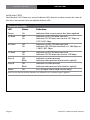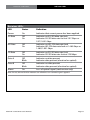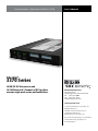
1
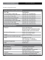
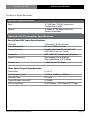
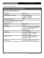
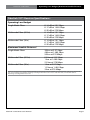
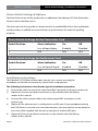
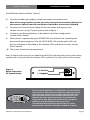
Communications Specialties’ Fiberlink® 3370
User’s Manual
Broadcast quality 3G/HD/SD-SDI,
10/100 Ethernet and 2 channels of
RS-Type data over one single
mode or two multimode fibers.
All data channels are available
simultaneously!
Fiberlink®
3370 Series
3G/HD/SD-SDI Transmission and
10/100 Ethernet & 2 Channels of RS-Type Data
over one single mode or two multimode fibers.
World Headquarters
55 Cabot Court
Hauppauge, New York 11788 USA
Tel: (631) 273-0404
Fax: (631) 273-1638
[email protected]
commspecial.com
Fiberlink® 3370 Series
Contents
Contents
Welcome . . . . . . . . . . . . . . . . . . . . . . . . . . . . . . . . . . . . . . . . . . . . . . . . . . . . . . . . . . . . . . . . . . 3
Features. . . . . . . . . . . . . . . . . . . . . . . . . . . . . . . . . . . . . . . . . . . . . . . . . . . . . . . . . . . . . . . . . . . 3
Package Contents. . . . . . . . . . . . . . . . . . . . . . . . . . . . . . . . . . . . . . . . . . . . . . . . . . . . . . . . . . 3
Technical Specifications
Model Part Number Specifications. . . . . . . . . . . . . . . . . . . . . . . . . . . . . . . . . . . . . 4
General Specifications. . . . . . . . . . . . . . . . . . . . . . . . . . . . . . . . . . . . . . . . . . . . . . . . . 4
Transmitter Specifications. . . . . . . . . . . . . . . . . . . . . . . . . . . . . . . . . . . . . . . . . . . . . 5
Receiver Specifications. . . . . . . . . . . . . . . . . . . . . . . . . . . . . . . . . . . . . . . . . . . . . . . . 6
Operating Loss Budgets. . . . . . . . . . . . . . . . . . . . . . . . . . . . . . . . . . . . . . . . . . . . . . . 7
Maximum Useable Distance. . . . . . . . . . . . . . . . . . . . . . . . . . . . . . . . . . . . . . . . . . . 7
Alarm Switch Settings. . . . . . . . . . . . . . . . . . . . . . . . . . . . . . . . . . . . . . . . . . . . . . . . . . . . . . 8
Installation Instructions. . . . . . . . . . . . . . . . . . . . . . . . . . . . . . . . . . . . . . . . . . . . . . . . . . . . 8
Data Configuration (Box Version). . . . . . . . . . . . . . . . . . . . . . . . . . . . . . . . . . . . . . . . . 10
Baud Rate Settings. . . . . . . . . . . . . . . . . . . . . . . . . . . . . . . . . . . . . . . . . . . . . . . . . . 11
Ethernet Settings. . . . . . . . . . . . . . . . . . . . . . . . . . . . . . . . . . . . . . . . . . . . . . . . . . . . 12
RS-Type Data Settings. . . . . . . . . . . . . . . . . . . . . . . . . . . . . . . . . . . . . . . . . . . . . . . 12
Data Wiring. . . . . . . . . . . . . . . . . . . . . . . . . . . . . . . . . . . . . . . . . . . . . . . . . . . . . . . . . 13
Data Configuration (Card Version) . . . . . . . . . . . . . . . . . . . . . . . . . . . . . . . . . . . . . . . . 14
Baud Rate Settings. . . . . . . . . . . . . . . . . . . . . . . . . . . . . . . . . . . . . . . . . . . . . . . . . . 15
Ethernet Settings. . . . . . . . . . . . . . . . . . . . . . . . . . . . . . . . . . . . . . . . . . . . . . . . . . . . 16
RS-Type Data Settings. . . . . . . . . . . . . . . . . . . . . . . . . . . . . . . . . . . . . . . . . . . . . . . 16
Data Wiring. . . . . . . . . . . . . . . . . . . . . . . . . . . . . . . . . . . . . . . . . . . . . . . . . . . . . . . . . 17
Indicator LEDs . . . . . . . . . . . . . . . . . . . . . . . . . . . . . . . . . . . . . . . . . . . . . . . . . . . . . . . . . . . 18
Operating Pointers. . . . . . . . . . . . . . . . . . . . . . . . . . . . . . . . . . . . . . . . . . . . . . . . . . . . . . . 20
Troubleshooting. . . . . . . . . . . . . . . . . . . . . . . . . . . . . . . . . . . . . . . . . . . . . . . . . . . . . . . . . 20
Maintenance and Repairs . . . . . . . . . . . . . . . . . . . . . . . . . . . . . . . . . . . . . . . . . . . . . . . . 21
Certifications . . . . . . . . . . . . . . . . . . . . . . . . . . . . . . . . . . . . . . . . . . . . . . . . . . . . . . . . . . . . 21
Warranty . . . . . . . . . . . . . . . . . . . . . . . . . . . . . . . . . . . . . . . . . . . . . . . . . . . . . . . . . . . . . . . . 22
Accessories and Related Products . . . . . . . . . . . . . . . . . . . . . . . . . . . . . . . . . . . . . . . . 23
Page 2
Fiberlink® 3370 Series User’s Manual
Fiberlink® 3370 Series
Welcome | Features | Package Contents
Welcome
Thank you for purchasing Communications Specialties, Inc.’s Fiberlink® 3370 Series. The
3370 Series is used to transmit 3G/HD/SD-SDI over one single mode fiber or two multimode
fibers as well as 10/100 Ethernet and two channels of RS-Type data. The Fiberlink 3370
series is compatible with single mode or multimode fiber. The system delivers noise-free
transmission that retains all of the signals’ initial parameters, regardless of fiber optic cable
attenuation. The 3370 Series also provides immunity to video pathological signals over the
entire link budget and operating temperature range.
Features
•Transmit up to 2 channels of bi-directional RS-Type data.
•Transmit 10/100 Base-T Ethernet
•All data and ethernet channels available simultaneously
•SDI signal is equalized and re-clocked prior to fiber optic transmission
•Receiver features a re-clocked SDI output
•Immunity to pathological patterns over entire link budget and operating
temperature range
•Compliant with SMPTE 259M-2006, 292-2006, 424M-2006, 276M
•Supports one single mode fiber or two multimode fibers
•Supports 3G/HD/SD-SDI inputs with or without embedded audio and data
•14 dB Optical Link Budget @ 2.97 Gbps
•Wide operating temperature range: -10º C to +50º C
•Available in Box and Card versions
•ST or LC connectors available
• Designed and Manufactured in the USA by CSI
Package Contents
•One Fiberlink® Unit (3370, 3371, 3372 or 3373)
•This User’s Manual
• One Ethernet Crossover Cable
Fiberlink® 3370 Series User’s Manual
Page 3
Technical Specifications
Fiberlink® 3370 Series
Technical Specifications
Model Part Number Specification
Unit Type
Part Number
Transmitter Box (1 Fiber, SM)
Transmitter Rack Card (1 Fiber, SM)
Receiver Box (1 Fiber, SM)
Receiver Rack Card (1 Fiber SM)
Transmitter Box (2 Fiber, MM)
Transmitter Rack Card (2 Fiber, MM)
Receiver Box (2 Fiber, MM)
Receiver Rack Card (2 Fiber MM)
3370-B7L (LC)
3370-C7L (LC)
3371-B7L (LC)
3371-C7L (LC)
3372-B7L (LC)
3372-C7L (LC)
3373-B7L (LC)
3373-C7L (LC)
3370-B7S (ST)
3370-C7S (ST)
3371-B7S (ST)
3371-C7S (ST)
3372-B7S (ST)
3372-C7S (ST)
3373-B7S (ST)
3373-C7S (ST)
General Specifications
Indicators
Box Version Dimensions
Weight
Number of slots in 6000A card cage
Power
Operating Temperature
MTBF
Power, Data Rate lock
(3G, HD, SD), Alarm (card version only),
RS-Data Channel 1, RS-Data Channel 2
& Ethernet LEDs on RJ-45 Connector
6.5 W x 1.15 H x 8 L (inches)
165 W x 29 H x 203 L (mm)
approx. 1 lb.; 0.45 kg
2
9-24 volts, AC or DC
3370: 4.8 watts, 16.4 BTU/Hr
3371: 4.65 watt s, 15.87 BTU/Hr
-10ºC to +50ºC
36,000 Hours
Data Specifications:
Data Channels
Data Bandwidth
Control Format
Protocols
Signal Connectors:
Page 4
2 Channels, Bi-Directional
DC to 115 Kb/sec, max.
Switch selectable RS-232, RS-422
& RS-485 (4 wire or 2 wire);
NRZ, NRZI, RZ, Manchester, Bi-phase
Removable terminal block Data
Fiberlink® 3370 Series User’s Manual
Technical Specifications
Fiberlink® 3370 Series
Technical Specifications
Ethernet Specifications:
Port:
Speed:
10/100 Base-T, RJ-45 connector,
Configured as MDI
10 Mbps & 100 Mbps Ethernet,
Switch Selectable
Fiberlink 3370 Transmitter Specifications:
Serial Video BNC Input Specifications
Channels
Data Bandwidth
Control Format
Protocols
Signal Connectors:
2 Channels, Bi-Directional
DC to 115 Kb/sec, max.
Switch selectable RS-232, RS-422
& RS-485 (4 wire or 2 wire);
NRZ, NRZI, RZ, Manchester, Bi-phase
Removable terminal block
Gbps and 350m at 270 Mbps
Return Loss
>10dB up to 2.97 Gbps
Fiber Optic Output Specifications
Connector
Wavelengths Used
Emmiter Type
Output Power (nominal)
SDI Re-clocking
Fiberlink® 3370 Series User’s Manual
LC or ST
1310nm, 1490nm, 1550nm
FP Laser
-4.5 dBm
At 270 Mbps, 1.485 Gbps & 2.97 Gbps
Page 5
Technical Specifications
Fiberlink® 3370 Series
Technical Specifications
Fiberlink 3371 Receiver Specifications:
Fiber Optic Input Specifications
Connector
Wavelength
Minimum Input Sensitivity
Maximum Input Power
LC or ST
1100 - 1620 nm
-17 dBm at 2.97 Gbps;
-22 dBm at 1.485 Gbps
-24 dBm at 270 Mbps;
0 dBm
Serial Video BNC Output Specifications
Number of Outputs
Signal Level
DC Offset
Rise/Fall Time
Overshoot
Timing Jitter
Alignment Jitter
1
800mV ± 10%
0V ± 0.5V
< 135 ps at 2.97 Gbps per SMPTE 424M;
< 270 ps at 1.485 Gbps per SMPTE 292;
0.4 ns to 1.5 ns at 270 Mbps
per SMPTE 259M
< 10% of amplitude
< 0.2 UI at 270 Mbps; < 1.0 UI at
1.485 Gbps; < 2.0 UI at 2.97 Gbps
with color bar signal
< 0.2 UI at 270 Mbps; < 0.2 UI at
1.485 Gbps; < 0.3 UI at 2.97 Gbps
with color bar signal
Re-clocking
At 270 Mbps, 1.485 Gbps & 2.97 Gb
Page 6
Fiberlink® 3370 Series User’s Manual
Fiberlink® 3370 Series
Operating Loss Budget | Maximum Useable Distance
Fiberlink 3371 Receiver Specifications:
Operating Loss Budget
Single Mode Fiber
Multimode Fiber (62.5u)
Multimode Fiber (50u)
0-14 dB at 2.97 Gbps
0-17 dB at 1.485 Gbps
0-20 dB at 270 Mbps
0-14 dB at 2.97 Gbps
0-17 dB at 1.485 Gbps
0-20 dB at 270 Mbps
0-14 dB at 2.97 Gbps
0-17 dB at 1.485 Gbps
0-20 dB at 270 Mbps
Maximum Useable Distance*
Single Mode Fiber
Multimode Fiber (62.5u)
Multimode Fiber (50u)
30 km at 2.97 Gbps
48 km at 1.485 Gbps
50 km at 270 Mbps
0.8 km at 2.97 Gbps
1 km at 1.485 Gbps
2.5 km at 270 Mbps
1 km at 2.97 Gbps
1.3 km at 1.485 Gbps
3 km at 270 Mbps
*Distance specifications are approximate, based upon connecting a 3370 Transmitter to a 3370 Receiver, and are not guaranteed.
CSI cannot estimate or guarantee operating loss budgets when the 3370 Series is used with other, non-Fiberlink devices.
Operating loss budget must not be exce
Fiberlink® 3370 Series User’s Manual
Page 7
Alarm Switch Settings | Installation Instructions
Fiberlink® 3370 Series
Alarm Switch Settings & Options
The Rack Card version of this product has an additional red indicator LED that illuminates
when an alarm condition exists.
The rack card unit also provides an output to drive a model 6020A Alarm Sensing Module
which provides an audible tone and activates a set of contacts for external signaling
purposes.
Alarm Switch Settings for the Transmitter Card
Switch Position
Alarm Indication
On
Off
1
Loss of Input Video
Enabled
Disabled
2
N/A
N/A
N/A
Alarm Switch Settings for the Receiver Card
Switch Position
Alarm Indication
On
Off
1
Loss of Optical Signal
Enabled
Disabled
2
N/A
N/A
N/A
Installation Instructions
The Fiberlink® 3370 Series of fiber optic transmission systems are ready for
immediate use and do not require any special tools or equipment.
The following instructions describe the typical installation procedure:
1) Connect the video source to the video input BNC connector on the transmitter unit.
2) (Optional) Connect your data connections as described in the Data Wiring
section of this manual.
3) Connect the video output cable to the video output BNC connectors on the
receiver unit.
4) (Optional) The ethernet port is configured as an MDI port. If you are not connecting
the 3370 Series to an auto-crossover ethernet port, you may need to use the ethernet
crossover cable supplied with the unit to connect to another MDI port.
5) (Optional) Connect your data connections as described in the Data Wiring
section of this manual.
Page 8
Fiberlink® 3370 Series User’s Manual
Installation Instructions
Fiberlink® 3370 Series
Installation Instructions (cont.)
6) Connect the fiber optic cable(s) to the transmitter and receiver units.
Note: when using two fiber version, you must connect the transmitters Optical A to
the receivers Optical A and the transmitters Optical B to the receivers Optical B.
7) Connect the Universal Power Supply to the transmitter and receiver units.
For box versions using DC power, please refer to figure 1.
8) Configure your data preferences as described in the Data Configuration
section of this manual.
9) When power is applied, the green POWER LED should illuminate, indicating the
presence of operating power. The 3G/HD/SD RATE LED and the audio LEDs will
give an indication as described in the Indicator LED’s and Alarm Circuitry section
of this manual.
10) The system should now be operational.
Note: The Rack Card version has an additional red LED for indicating the presence of an alarm
condition (loss of signal). Refer to Indicator LED’s and Alarm Circuitry sections of this manual.
Figure 1:
Power Connector
DC Input Polarity
(+) Positive
( - ) Negative
9-24 Volts
AC or DC
The transmitting element in the Fiberlink® 3370 transmitter
unit contains a solid state Laser Diode located in the optical
connector. This device emits invisible infrared electromagnetic radiation which can be harmful to human eyes. The
radiation from this optical connector, if viewed at close
range with no fiber optic cable connected to the optical
connector, may be sufficient intensity to cause
instantaneous damage to the retina of the eye. Direct
viewing of this radiation should be avoided at all times!
Fiberlink® 3370 Series User’s Manual
Page 9
Data Configuration (Box Version)
Fiberlink® 3370 Series
Data Configuration (Box Version):
The Fiberlink 3370 Series box units have two dip switch panels, one with 10 switches, one
with 9. The first panel, “Data Config A”, represents the Ethernet and RS Channel A
configuration. The second panel, “Data Config B”, represents RS Channel B configuration.
Note that all data channels are available simultaneously.
E 1 2 3 4 5 6 7 8 9
DATA CONFIG A
Data Mode
Baud Rate
2 Wire/4 Wire Mode
Termination (Input 120 Ohm)
Termination (Output 120 Ohm)
Ethernet
1 2 3 4 5 6 7 8 9
DATA CONFIG B
Data Mode
Baud Rate
2 Wire/4 Wire Mode
Termination (Input 120 Ohm)
Termination (Output 120 Ohm)
Page 10
Fiberlink® 3370 Series User’s Manual
Fiberlink® 3370 Series
Data Configuration | Baud Rates (Box Version)
Baud Rate Configuration
E 1 2 3 4 5 6 7 8 9
1 2 3 4 5 6 7 8 9
DATA CONFIG A
DATA CONFIG B
E 1 2 3 4 5 6 7 8 9
1 2 3 4 5 6 7 8 9
DATA CONFIG A
DATA CONFIG B
E 1 2 3 4 5 6 7 8 9
1 2 3 4 5 6 7 8 9
DATA CONFIG A
DATA CONFIG B
E 1 2 3 4 5 6 7 8 9
1 2 3 4 5 6 7 8 9
DATA CONFIG A
DATA CONFIG B
E 1 2 3 4 5 6 7 8 9
1 2 3 4 5 6 7 8 9
DATA CONFIG A
DATA CONFIG B
E 1 2 3 4 5 6 7 8 9
1 2 3 4 5 6 7 8 9
DATA CONFIG A
DATA CONFIG B
E 1 2 3 4 5 6 7 8 9
1 2 3 4 5 6 7 8 9
DATA CONFIG A
DATA CONFIG B
2400
4800
9600
19.2k
38.4k
57.6k
76.8k
Fiberlink® 3370 Series User’s Manual
Page 11
Fiberlink® 3370 Series
Data Configuration (Box Version)
Ethernet Configurations
E 1 2 3 4 5 6 7 8 9
1 2 3 4 5 6 7 8 9
100 Base-T Ethernet
DATA CONFIG A
DATA CONFIG B
E 1 2 3 4 5 6 7 8 9
1 2 3 4 5 6 7 8 9
DATA CONFIG A
DATA CONFIG B
E 1 2 3 4 5 6 7 8 9
1 2 3 4 5 6 7 8 9
DATA CONFIG A
DATA CONFIG B
E 1 2 3 4 5 6 7 8 9
1 2 3 4 5 6 7 8 9
DATA CONFIG A
DATA CONFIG B
E 1 2 3 4 5 6 7 8 9
1 2 3 4 5 6 7 8 9
DATA CONFIG A
DATA CONFIG B
10 Base-T Ethernet
RS-232
RS-485/422 4 Wire
RS-485 2 Wire T/R
Page 12
Fiberlink® 3370 Series User’s Manual
Data Wiring (Box Version)
Fiberlink® 3370 Series
Data Wiring:
RS-Type data wiring for the Fiberlink 3370 Series is as follows:
RS-232 Input
G 1 2 3 4 G 1 2 3 4
Channel A
Channel B
RS-422/485 - 4 Wire Input
G 1 2 3 4 G 1 2 3 4
+ –
Channel A
+ –
Channel B
RS-232 Output
G 1 2 3 4 G 1 2 3 4
Channel A
Channel B
RS-422/485 - 4 Wire Output
G 1 2 3 4 G 1 2 3 4
+ –
Channel A
+ –
Channel B
RS-485 - 2 Wire Input/Output
G 1 2 3 4 G 1 2 3 4
+ –
Channel A
+ –
Channel B
Fiberlink® 3370 Series User’s Manual
Page 13
Data Configuration (Card Version)
Fiberlink® 3370 Series
Data Configuration (Card Version):
The Fiberlink 3370 Series card units have two dip switch panels with 10 switches. The first
panel, “DATA CONFIG A”, represents the Ethernet and RS Channel A configuration. The
second panel, “DATA CONFIG B”, represents RS Channel B configuration. Note that all data
channels are available
simultaneously.
1 2 3 4 5 6 7 8 9 10
DATA CONFIG A
Data Mode
Baud Rate
2 Wire/4 Wire Mode
Termination (Input 120 Ohm)
Termination (Output 120 Ohm)
Ethernet
1 2 3 4 5 6 7 8 9 10
DATA CONFIG B
Not Used
Data Mode
Baud Rate
2/4 Wire Mode
Termination (Input 120 Ohm)
Termination (Output 120 Ohm)
Page 14
Fiberlink® 3370 Series User’s Manual
Fiberlink® 3370 Series
Data Configuration | Baud Rates (Card Version)
Baud Rate Configuration
1 2 3 4 5 6 7 8 9 10
1 2 3 4 5 6 7 8 9 10
DATA CONFIG A
DATA CONFIG B
1 2 3 4 5 6 7 8 9 10
1 2 3 4 5 6 7 8 9 10
DATA CONFIG A
DATA CONFIG B
1 2 3 4 5 6 7 8 9 10
1 2 3 4 5 6 7 8 9 10
DATA CONFIG A
DATA CONFIG B
1 2 3 4 5 6 7 8 9 10
1 2 3 4 5 6 7 8 9 10
DATA CONFIG A
DATA CONFIG B
1 2 3 4 5 6 7 8 9 10
1 2 3 4 5 6 7 8 9 10
DATA CONFIG A
DATA CONFIG B
1 2 3 4 5 6 7 8 9 10
1 2 3 4 5 6 7 8 9 10
DATA CONFIG A
DATA CONFIG B
1 2 3 4 5 6 7 8 9 10
1 2 3 4 5 6 7 8 9 10
DATA CONFIG A
DATA CONFIG B
2400
4800
9600
19.2k
38.4k
57.6k
76.8k
Fiberlink® 3370 Series User’s Manual
Page 15
Fiberlink® 3370 Series
Data Configuration (Card Version)
Ethernet Configurations
1 2 3 4 5 6 7 8 9 10
1 2 3 4 5 6 7 8 9 10
DATA CONFIG A
DATA CONFIG B
1 2 3 4 5 6 7 8 9 10
1 2 3 4 5 6 7 8 9 10
DATA CONFIG A
S1
1 2 3 4 5 6 7 8 9 10
1 2 3 4 5 6 7 8 9 10
DATA CONFIG A
DATA CONFIG B
1 2 3 4 5 6 7 8 9 10
1 2 3 4 5 6 7 8 9 10
DATA CONFIG A
DATA CONFIG B
1 2 3 4 5 6 7 8 9 10
1 2 3 4 5 6 7 8 9 10
DATA CONFIG A
DATA CONFIG B
10 Base-T Ethernet
100 Base-T Ethernet
RS-232
RS-485/422 4 Wire
RS-485 2 Wire T/R
Page 16
Fiberlink® 3370 Series User’s Manual
Fiberlink® 3370 Series
Data Wiring (Card Version)
Data Wiring:
RS-Type data wiring for the Fiberlink 3370 Series card units is as follows:
G 1 2 3 4
Data A
G 1 2 3 4
Data B
RS-232 Input
G 1 2 3 4
RS-232 Output
G 1 2 3 4
Data A
G 1 2 3 4
Data A
G 1 2 3 4
Data B
RS-422/485 - 4 Wire Input
G 1 2 3 4
Data B
RS-422/485 - 4 Wire Output
G 1 2 3 4
Data A
G 1 2 3 4
Data A
G 1 2 3 4
Data B
+ –
Data B
+ –
RS-485 - 2 Wire Input/Output
G 1 2 3 4
Data A
G 1 2 3 4
Data B
+ –
Fiberlink® 3370 Series User’s Manual
Page 17
Indicator LEDs
Fiberlink® 3370 Series
Indicator LEDs
The Fiberlink® 3370 Series has several indicator LEDs that are used to monitor the state of
the unit. Card versions have an additional Alarm LED.
Transmitter LEDs
LED
Status
Definition
Power
On
Indicates that correct power has been applied.
3G Rate
Off
On
Indicates no 3G-SDI data rate lock
Indicates 3G-SDI data rate lock at 2.97 Gbps or
2.97/1.001 Gbps
HD Rate
Off
On Indicates no HD-SDI data rate lock
Indicates HD-SDI data rate lock at 1.485 Gbps or
1.485/1.001 Gbps
SD Rate
Off
On Indicates no SD-SDI data rate lock
Indicates SD-SDI data rate lock at 270 Mbps
Data A
Off
Blink
Indicates no data present
Indicates data present (electrical or optical)
Data B
Off
Blink
Indicates no data present
Indicates data present (electrical or optical)
Alarm
On Loss of input video (card version only)
Note: The 3G, HD and SD LEDs indicators are off when a non-standard signal is applied.
Page 18
Fiberlink® 3370 Series User’s Manual
Indicator LEDs
Fiberlink® 3370 Series
Receiver LEDs
LED
Status
Definition
Power
On
Indicates that correct power has been applied.
3G Rate
Off
On
Indicates no 3G-SDI data rate lock
Indicates 3G-SDI data rate lock at 2.97 Gbps or
2.97/1.001 Gbps
HD Rate
Off
On Indicates no HD-SDI data rate lock
Indicates HD-SDI data rate lock at 1.485 Gbps or
1.485/1.001 Gbps
SD Rate
Off
On Indicates no SD-SDI data rate lock
Indicates SD-SDI data rate lock at 270 Mbps
Data A
Off
Blink
Indicates no data present
Indicates data present (electrical or optical)
Data B
Off
Blink
Indicates no data present
Indicates data present (electrical or optical)
Alarm
On Loss of optical signal (card version only)
Note: The 3G, HD and SD LEDs indicators are off when a non-standard signal is applied.
Fiberlink® 3370 Series User’s Manual
Page 19
Fiberlink® 3370 Series
Operating Pointers | Troubleshooting
Operating Pointers
Remember to check attenuation of the fiber optic cable. The system will only operate
properly if these specifications fall within the range of the system’s loss budget.
Note: If no signal is applied to the 3370 Transmitter, no optical power will be present on the
3370 Transmitter’s output.
Troubleshooting
Multimode fiber optic cable contains an optical fiber with a light carrying “core” that is
only .0025 inches (62.5 microns) in diameter. Single mode fiber optic cable has an even
smaller “core,” only .00032 to .0004 inches (8-10 microns). This is smaller than a human hair!
Therefore, any minute particles of dirt or dust can easily block the fiber from accepting or
radiating light. To prevent this from happening, always use the provided dust caps when
ever optical connectors are exposed to air. It is also a good idea to gently clean the tip of an
optical connector with a lint-free cloth moistened with alcohol whenever dust is suspected.
The status of the LEDs should provide the first clue as to the origin of any operational
failure. If these are off, it usually means that the fiber is broken or has too much attenuation.
Next, be certain that the input and output signal connections are correct.
An optical power meter, such as the Fiberlink® 6615, a visible light source, such as the
Fiberlink® 6610, and a Three Wavelength Light Source, such as the Fiberlink® 6620, can
greatly assist and expedite troubleshooting of fiber optic transmission systems and are
recommended tools all installers should have available.
Finally, although multimode and single mode devices may look the same, they will not
operate properly together. Using the wrong device or fiber can easily add more attenuation
than specified, resulting in poor overall performance. It should be noted that some of our
fiber optic products support both single mode and multimode fiber in the same unit.
If, after reviewing the above possibilities, the system is still not operating, please contact
the Customer Service Department for further assistance. If you suspect your problem is
caused by the optics or the fiber optic cable, and you have an optical power meter, please
take the appropriate measurements prior to contacting support.
Page 20
Fiberlink® 3370 Series User’s Manual
Fiberlink® 3370 Series
Maintenance and Repairs | Certifications
Maintenance and Repairs
The Fiberlink® 3370 Series has been manufactured using the latest semiconductor devices
and techniques that electronic technology has to offer. They have been designed for long,
reliable and trouble-free service and are not normally field repairable.
Should difficulty be encountered, Communications Specialties maintains a complete
service facility to render accurate, timely and reliable service of all products.
The only maintenance that can be provided by the user is to ascertain that optical
connectors are free of dust or dirt that could interfere with light transmission and that
electrical connections are secure and accurate. Please see the Troubleshooting section of
this manual for additional information.
An optical power meter, such as the Fiberlink® 6615, a visible light source, such as the
Fiberlink® 6610, and a Three Wavelength Light Source, such as the Fiberlink® 6620, can
greatly assist and expedite troubleshooting of fiber optic transmission systems and are
recommended tools all installers should have available.
All other questions or comments should be directed to our Customer Service Department.
It should be noted that many “problems” can easily be solved by a simple telephone call.
If you suspect your problem is caused by the optics or the fiber optic cable, and you have
an optical power meter, please take the appropriate measurements prior to contacting
support.
Certifications
Fiberlink® 3370 Series User’s Manual
Page 21
Fiberlink® 3370 Series
Warranty
Communications Specialties, Inc. (CSI) warrants that, for a period of three years after
purchase by the Buyer, this product will be free from defects in material and workmanship
under normal use and service. A Return Material Authorization (RMA) number must be
obtained from CSI before any equipment is returned by the Buyer. All materials must be
shipped to CSI at the expense and risk of the Buyer.
CSI’s obligation under this warranty will be limited, at its option, to either the repair or
replacement of defective units, including free materials and labor. In no event shall CSI be
responsible for any incidental or consequential damages or loss of profits or goodwill.
CSI shall not be obligated to replace or repair equipment that has been damaged by fire,
war, acts of God, or similar causes, or equipment that has been serviced by unauthorized
personnel, altered, improperly installed, or abused.
RMA numbers and repairs can be obtained from:
Communications Specialties, Inc.
55 Cabot Court
Hauppauge, NY 11788 USA
Tel: (631) 273-0404
Fax: (631) 273-1638
RMA numbers can also be obtained from our web site: commspecial.com
Please have your serial number available.
Page 22
Fiberlink® 3370 Series User’s Manual
Fiberlink® 3370 Series
Accessories and Related Products
Fiberlink® 6610 Visible Light Source
The Fiberlink® Visible Light Source provides a
visible 650 nm laser output that can be used for
identifying fiber breaks and individual fibers within
fiber bundles, allowing for convenient, on-site
testing of fiber networks during construction
and maintenance procedures.
Fiberlink® 6615 Optical Power Meter
The Fiberlink® Optical Power Meter measures the
power of optical signals at 850, 980, 1310 and 1550
nm wavelengths, allowing for convenient, on-site
testing of fiber networks during construction and
maintenance procedures. It can be used to measure
the power of an optical signal reaching the receiving
end of a fiber optic cable, as generated either by a
transmitter unit or by a light source such as the 6620.
Fiberlink® 6620
Three Wavelength Light Source
The Fiberlink® Three Wavelength Light Source offers a
laser output at wavelengths of 1310 and 1550 nm and
VCSEL output at 850 nm, allowing for convenient,
on-site testing of fiber networks during construction
and maintenance procedures.
Fiberlink® 3370 Series User’s Manual
Page 23
Communications Specialties’ Fiberlink® 3370
User’s Manual
Fiberlink®
3370 Series
3G/HD/SD-SDI Transmission and
10/100 Ethernet & 2 Channels of RS-Type Data
over one single mode or two multimode fibers.
World Headquarters
55 Cabot Court
Hauppauge, New York 11788 USA
Tel: (631) 273-0404
Fax: (631) 273-1638
[email protected]
commspecial.com
©2011 Communications Specialties, Inc.
All Rights Reserved.
Fiberlink and the starburst logo are
registered trademarks of
Communications Specialties, Inc.
CSI and the triangle designs are trademarks
of Communications Specialties, Inc.
P/N 128916 Rev. E