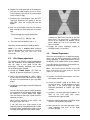
1
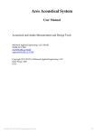
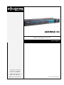
AUDIMAX 362
3 bands audio processor for FM
Users manual
3 de Febrero 3254 (1429)
Buenos Aires - Argentina
Tel: +54 11 4702 0090
e-mail: [email protected]
Fax: +54 11 4702 2375
Web: www.SolidynePRO.com
Last revision: 20010 August 10
Pág. 2
AUDIMAX 362
SOLIDYNE
Table of contents
Chapter 1 – Installation ............................................................................................................................... 5
2.1
2.2
2.3
Generalities ...............................................................................................................................................5
Power source ............................................................................................................................................5
What’s in the box?.....................................................................................................................................5
2.4
Wiring .......................................................................................................................................................5
2.5
2.6
MPX Output ..............................................................................................................................................5
Humming ..................................................................................................................................................5
2.7
2.7.1
Aditional information: Balanced and unbalanced wiring..............................................................................6
Balancead lines........................................................................................................................................6
2.7.2
Unbalanced lines......................................................................................................................................6
2.7.3
2.7.4
Unbalanced output to balanced input........................................................................................................6
Balanced output to unbalanced input ........................................................................................................6
Chapter 2 – Theory of audio processors..................................................................................................... 7
2.1
A brief story... ..........................................................................................................................................7
2.2
Audimax 362 overview .............................................................................................................................8
2.2.1
Introduction..............................................................................................................................................8
2.2.2
Blocks Diagram........................................................................................................................................9
Processing Stages.....................................................................................................................................9
1.2
Stage 1 – Peak Asymmetry Canceller......................................................................................................................9
Stage 2 – Input Expander ........................................................................................................................................9
Stage 3 – Level Input Control ................................................................................................................................10
Stage 4 – Multiband Compressors.........................................................................................................................10
Stage 7 – Stereo Coder .........................................................................................................................................11
MPX processing ....................................................................................................................................................12
Chapter 3 – Operation .............................................................................................................................. 13
3.1
3.2
3.2.1
3.2.2
Starting Up - MPX level...............................................................................................................................13
Audimax MPX output level......................................................................................................................13
Audio settings..........................................................................................................................................13
Input level ..............................................................................................................................................13
Customizing the sound...........................................................................................................................13
Chapter 4 – SC 100 stereo coder calibration............................................................................................ 15
4.1
4.2
4.3
Test points diagram (components side) ...................................................................................................15
Verify Pilot Level......................................................................................................................................15
Pilot Phase adjustment............................................................................................................................16
4.4
Channel Separation .................................................................................................................................16
4.5
4.6
Measurement of Residual Noise ..............................................................................................................17
Audio distortion measurements ...............................................................................................................17
Chapter 5 – Technical Specifications....................................................................................................... 19
SOLIDYNE
AUDIMAX 362
Pág. 3
Pág. 4
AUDIMAX 362
SOLIDYNE
Chapter 1 – Installation
2.1
What’s in the box?
The AudiMax-362 packaging include:
1 Power cord.
1 Guarantee agreement.
4 self-adhesive rubber supports.
Generalities
the
2
Señal (+)
3
Señal (-)
Inputs and outputs are electronically balanced.
Inputs come from factory in "bridging" mode, with
impedance bigger than 10 Kohms. They must be
connected to 600 ohms console’s outputs. For old
consoles that only works with real 600 ohms loads
at the output, place a 620 ohms resistor inside the
XLR input connectors, connected between pins 2
and 3.
1 User’s manual.
Please
read
carefully
recommendations:
Tierra
Conectores de entrada y salida
1 AudiMax-362 Processor (include supports for
rack montage).
2.2
1
following
• Audimax 362 processors are designed for rack
montage in 19” standard racks. Also it can be
used on a table or desktop, quitting the lateral
supports.
2.5
MPX Output
For MPX output use 52 ohms coaxial cable. The
connector is a BNC. The maximum length for this
cable can be 50 meters.
• The room temperature must be between 5 and
40°C (41°/104° F). Avoid the direct solar ray
incidence on the equipment. Avoid the proximity
of heat sources and high electromagnetic fields
(high power transformers, motors, etc). 462-MKII
have internal protection against RF fields, that
allows assembly it next to AM/FM RF amplifiers.
Is very important to have a adequate ground
installation. In case of doubt, refers to your
Solidyne dealer.
• The installation in very humid places or with saline
atmosphere will have to be avoided, since they
will can cause corrosion in the printed circuit
board and electronic component.
2.6
2.3
Power source
Verify the correct position of the AC120/220
voltage switch, located on the rear panel. The
variation of the AC voltage must be smaller than
10%. Otherwise, use tension stabilizers of fast
action.
When use the MPX input of the transmitter, make
sure that the internal pre-emphasis stage is
disabled (flat response between 20 – 100 KHz).
Humming
If some residual humming appears when the
system is started up; turn off the unit. If humming
disappears, check the 462 input connections. If
the humming still here; unplug the MPX cable. If
humming ends, this indicates that a problem
occurs with the ground connections.
Nevertheless, this problem rarely can occur since
the Audimax’s MPX output is differential type,
where the BNC connector has floating GND to
cancel possible humming.
The on/off switch locates on the rear panel.
2.4
Wiring
Use shielded twisted pair audio cables of good
quality for audio connections (microphone type).
Input and output connectors are XLR type (as is
standard, female for the inputs and male for the
outputs). Connect as the following table indicates:
SOLIDYNE
AUDIMAX 362
Pág. 5
2.7
2.7.3
ADITIONAL TECHNICAL
INFORMATION: Balanced and
unbalanced I/O
In the following paragraphs you will find
information about how to connect unbalanced
outs to balanced inputs, and vice versa. This
information will be of extreme utility, not only for
Audimax 362, but also for other equipment of your
radio. Different cases are decrypted.
In order to connect an unbalanced output to a
balanced input, you need to unbalance the
input. This is obtained sending to GND the
negative (-) terminal on the balanced input
connector, and connecting the other one to the
signal cable of unbalanced source. The ground of
the input must be connected to the output’s
ground (shield of the cable).
•
2.7.1
Balancead lines
Balanced lines use three cables to transmit the
signal: positive, negative and ground. The
negative takes the same audio signal of that the
positive but inverted 180°. GND corresponds to
the shield of the cable, which rejects the
electrostatic noise (switches, big motors, etc.).
The fact that the audio signal is sent by two
cables, inverted in one of them, practically annuls
the noise induced on the cable, specially the
electromagnetic one, caused by fluorescent tubes,
AC lines, etc.
A balanced input amplifies only the difference
between both positive and negative signal. Since
the induced noise causes the same deviation in
both cables, when reducing both signals the noise
is eliminated (the (-) wire invert its phase, then,
the induced noise is reduced to itself). In addition,
equipments that uses balanced I/O are of
professional category and uses line levels of
+4dBu (1,23 Volts). Connectors are XLR or stereo
plugs (one by channel).
2.7.2
Unbalanced output to balanced input
If the input is a stereo jack, the adaptation can
be made using a mono plug connected in the
following way: the shield to the sleeve and the
live to the tip. The sleeve of the mono plug will
send the negative terminal of balanced input
(jack’s ring) to GND.
• If the input is of XLR type, the shield of the
unbalanced cable must be connected to pins 1
and 3 and the live to pin 2.
2.7.4
Balanced output to unbalanced input
For this case, leave unconnected the negative (-)
wire of the balanced output, joining the positive to
the unbalanced input.
Unbalanced lines
They are used in “home” and non-professional
equipment. The audio is sent by a pair of cables;
being the one alive and other the shield of the
cable. These cables are much more sensible to
the noise, mainly of electromagnetic type. They
handle line levels of the order of -10dBv (0.36
Volts).
•
If the balanced output have a stereo jack
connector and you need to connect it to an input
with mono jack (unbalanced), you can use a
stereo plug-plug cable, but disconnecting the ring
on the input plug. The connection is made using
the tip (signal) and sleeve (GND).
•
If the output is XLR type, leave unconnected the
pin 3, and connect the live to pin 2 and the shield
to pin 1. The other ends of the cable will have
RCA or mono plug connector.
•
If the unbalanced input is stereo, and uses an
stereo jack, you need to make an special cable,
in which the plug’s tip is connected to left channel
and the ring to the right channel, in both cases
unbalanced as was explained.
The connectors typically used on this kind of units
are RCA o male plugs (TRS).
Pág. 6
AUDIMAX 362
SOLIDYNE
Chapter 2 – Theory of audio processors
NOTE: in order to complement the study of this subject is recommended to visit our WEB
(www.solidynepro.com). In the DEMO section there are a Power Point presentation called Audio Processors. It
has a complete Technical Appendix that it analyzes how the audio processing increases the coverage area of the
FM
stereo
transmission.
.
2.1 A brief story...
From mid of the 1930 decade, when appears the
first compressors and expanders units, to the
present time, all chains of audio for broadcasting
incorporate devices whose function is to alter the
dynamic range of the sound. The advance of the
technology improves these devices during the
‘70s.
The compressors, expanders and audio limiters
were gaining in efficiency and complexity. In the
beginning, its main parameters (attack and
recovery times, thresholds, etc.) were fixed by
design or by the operator, through the device’s
controls. In the '70s, these functions begin to be
automatic, based on the characteristics of the
audio signal, but having at the same time a
control on their action to be able to customize the
sound.
When five or more devices are grouped in a same
equipment, they begin to be denominated:
AUDIO PROCESSORS.
Since 1970, Solidyne introduces important
advances in this field, like the invention of a
control technique based on FET’s with guided
gate (see publication in Rev. Tel. Electrónica,
September/70). They follow diverse publications,
having particular international relevance the work
published in June/76 at the Journal of the Audio
Engineering Society, New York, U.S.A. where a
new concept was introduced, which persist to the
present time: PHSICOACUSTIC PROCESSING.
This new technique is the base for all the modern
audio processors for broadcasting use. The
necessity to process the phase to make
symmetrical the human voice waveform is
another one of the techniques that Solidyne has
introduced internationally (see mentioned article
AES). Today, Orban, Omnia, Aphex, etc use our
ideas.
The concept of psychoacoustic processing is
simple in essence, although of complex
accomplishment. It consists of analyzing the way
in which the sound is perceived by our ear,
considering diverse investigations and developed
acoustic models.
SOLIDYNE
AUDIMAX 362
The brain uses to process audio data, the
information that arrives through 30,000 nervous
fibers, originating at the Basilar membrane. Then,
it will be possible to be computed the auditory
reactions and to be governed all the aspects of
the audio processing. This way, the electronic
system works transforming the original signal into
another one, of greater energy and greater quality
of sound. Then, it will be possible to reduce the
dynamic range of the audio signals, to eliminate
the peaks, and even, to clip them partially to
increase its energy.
If this were made directly, obeying to purely
electronic concepts of efficiency, the quality would
be degraded and the sound would be very poor.
If, however, the psycho acoustic concepts are
applied, and factors like the aural masking, the
pre and post pulse inhibitions, the Hass effect, the
reflections at the ear pinna, the aural models of Dr
Karjalainen, etc; it will be possible to create a new
generation of processors that allow to important
increases of energy, increasing at the same time
the sensation of “Perceived Sound Quality”.
At the light of these discoveries the
psychoacoustics processing was defined in these
terms:
PHSYCO ACO ÚST I C PRO CESSI NG i s t h e
t e c h n i q u e t h a t a l l o ws t o i n c r e a s e t h e
r a n g e o f AM o r s t e r e o F M t r a n s m i s s i o n ,
by increasing the energy of the audio
signal, and also increasing the “quality
of sound” perceived by the listener.
Nevertheless, it is fundamental throughout this
process, to maintain very low the audio distortion
produced by harmonic and IM components. This
happens because the psychoacoustic processing
MODIFIES the waveform of the complex signal of
audio, but IT DOES NOT DISTORT IT. Since the
distortion concept, in this context, implies the
existence of a sound that offends the ear,
sounding unnatural.
Pág. 7
This is because the psychoacoustic processing
obtains that the ear accepts like of better quality
than the original one, to certain modifications of
the waveform.
But it does not mean an
"anesthesia" to the ear, to avoid perceiving the
distortions due to deficiencies in the quality of the
electronic circuits of the processors.
Considering that to obtain an excellent processing
is necessary, at the moment, to use between 7
and 10 stages of processors, the distortion of
each stage must be smaller than 0.01%. Greater
distortion values, will lead inexorably to a
degradation of the sound quality. You must
remember that has been demonstrated (Journal of
AES, Vol. 29,4,p.243), that is possible to measure
distortions of 0.05% through a common
loudspeaker (distortion bigger than 3%). This
demonstrates that one distortion do not mask
another one. A practical rule is, then:
ALL DISTORTION INTRODUCED IN THE AUDIO
CHAIN OF THE TRANSMITTER, THAT
EXCEEDS 0.05%, COULD BE LISTENED BY
THE AUDIENCE, EVEN THROUGH RECEIVERS
THAT HAVE VALUES OF DISTORSION 50
TIMES GREATER.
This, of course, is not a novelty for the conscious
audio engineers around the World.
Therefore, the line of SOLIDYNE processors has
distortion values smaller than 0,02%.
Few controls, easy adjustment, inviolable...
The psychoacoustic processors created by
Solidyne, have 70% of their functions
automatically fit, under the control of the audio
program. But they also present the essential
controls for customize the sound of the radio, that
you can adjust.
2.2 Audimax 362 overview
2.2.1
Introduction
The Audimax 362 has 7 processing stages and
the stereo coder. Its main characteristic is the
ease of use, because it doesn’t require a
specialized technician to start up and to adjust the
unit; and neither it has the critical “Input level”
control, since an automatic system adapts the
input gain to the output level of any audio
console, avoiding the more frequent operational
errors. His low cost is appropriate for low-power
FM radios, as well for recording studio of high
power radio stations. The 362-IT model is an
excellent processor for WEBcasting (radio on
Internet).
Operating in a FM radio, the AudiMax 362
increases the reach of the transmission,
improving the covered area between 30 and 50%,
obtaining an impressive audio quality that will
distinguish your radio station. The AudiMax sound
is smooth and warmth, with the classic
characteristics of the analogical processes of high
technology.
AudiMax 362 works with 3 bands and it’s
controlled totally by VCA (Voltage Controlled
Amplifiers). The stereo coder stage uses digital
synthesis with 16X oversampling, a technology
developed by Solidyne that guarantees ultra-low
distortion and high channel’s separation, not
requiring any readjustment during all its life utility.
MPX output is differential type, cancelling the
residual humming.
AudiMax 362 has a great advantage: it does not
have critical adjustments. This means that in any
position of his controls always it sounds well. The
adjustment can be made then by inexpert people.
Simply taking all the controls to the center
position, you have an excellent sound on the air.
From there customize the sound so that the radio
sounds as you desired (this it is a question of
personal taste).
Pág. 8
AUDIMAX 362
SOLIDYNE
2.2.2
Blocks Diagram
1.2
Processing Stages
the work of Oscar Bonello, published at the
Journal of AES, Vol.24,5 in which it is described,
for the first time, the theory of its operation.
Stage 1 – Peak Asymmetry Canceller
It is known that, by a particularity disposition of
the vocal cords, the sonorous emission that these
generate are asymmetric triangular pulses. The
three cavities that filter and shape these formants,
to obtain the vocal sounds, do not modify this
intrinsic characteristic of the human voice. All the
spoken word and still sung is strongly asymmetric.
This creates an important reduction of the energy
of the audio signal, particularly when it pass
through a compressor, because the compressor
sets its compression level for the greater peak,
does not concern its polarity. In this way, when a
polarity is fit to the 100%, the opposite polarity
hardly surpasses 50%, due to the asymmetry.
The fact that the music sounds louder than the
human voice, after pass through a compressor is
a phenomenon well known. This is because the
musical sounds are symmetrical, whereas the
human voice is not.
In order to correct this problem, WITHOUT
INTRODUCING ANY ALTERATION AT THE
SOUND QUALITY, peak asymmetry canceller is
used.
This technique, based in a discovery of the Dr
Leonard Kahn, acquires international validity with
SOLIDYNE
AUDIMAX 362
The peak asymmetry canceller is in essence an
all-pass network, a class of not minimum phase
network. That is: a network whose transference
function has zeros in the right semi plane. This
network has a full flat response to frequency; only
its phase response is function of the frequency.
This phase rotation, which must compliment very
particular conditions, is responsible of the peak
symmetry of the audio signals. Signals that by
their nature are symmetrical (like most of the
musical instruments), are not modified by this
processor.
This processor, by itself, allows to increase
between 3 and 5 dB the final power broadcast by
your transmitter (it is to say that it increases by a
factor of TWO the average power transmitted).
Numerous tests have been made in different
countries, to verify, in real conditions, these
results.
Stage 2 – Input Expander
The expander, previous to the compression
process, is an excellent resource to increase the
signal/noise ratio of the original program. This is
advisable, since the compression process, when
Pág. 9
reducing the high level passages, consequently
increases the relative level of the passages of low
level, and therefore the noise. This is a forced
consequence of the compression process that has
particular effect in the increasing of the ambient
noise of the microphones. In order to avoid that,
the Solidyne processors incorporate a linear
expander, previous to the compressor stage.
The concept of linear expander implies an
expander that works within a very wide range of
signals, below a threshold value. That means it
always expands within that range, for any level of
signal. That is to say that their curve of
transference, based on the input level, is a
straight line (from there the "linear" name). This
implies that by each 10 dB that the input level
reduces, the expander will reduce, for example,
13 dB. This happens for any input value, below
the threshold. Then if the input is reduced in 30
dB, the output will do it in 39 dB; that is to say that
the background noise has been reduced in 9 dB.
This way, the expander compensates the increase
of the noise that the compressor, like undesired
effect, will increase.
At this point, maybe you will be thinking that
DOES NOT HAVE SENSE to make an expander
of the signal and soon to compress it. You will
think, perhaps, that an effect cancels to the other.
But it’s not true for two reasons. First: the different
attack and recovery times. Second: multiband
compressors have elevated threshold, whereas
the linear expander has a very low threshold and
a linear behavior below the threshold. It means
that the actions do not cancel, because both
processes are not complementary.
The linear expander, to optimize its behavior, has
instantaneous attack and a fast recovery times.
Here is where the psychoacoustic concept “postpulse hearing inhibition” is used. This allows using
an expander with a quick recovery time, so that
the ear does not perceive it. The broadband
compressor that follows the expander has a very
slow recovery time. Therefore, with impulsive
signals, as the audio program, does not exist any
cancellation effect.
Another advantage of using a linear expander
previous to the processing is that an excellent
audible sensation of dynamic range is obtained.
In fact, recent studies have demonstrated that the
audible sensation produced by the level variations
of an audio signal, is related to the changes
happened in the first 50 milliseconds, and is little
dependent of the reached final value. This
implies that an expander in the short term is
perceived like a great dynamic range, whereas
the power sensation (and even the coverage area
Pág. 10
of the radio transmitter) is related to the
AVERAGE ENERGY, which depends of the
compression of the energy level.
You can see that they are two concepts different.
With audio processors of conventional design, the
expander and the compression were antagonistic
concepts. This does not happen in the field of the
psychoacoustics processors.
Stage 3 – Level Input Control
The Audimax-362 has an automatic control for the
input gain. Manual adjustments are not necessary.
The AGC (Automatic Gain Control) guarantee that
the audio signal enters to the delicate multiband
compressors always with the same level, avoiding
variations on the transmitted signal.
The AGC is designed to work with input levels
from –10 dBu to +15 dBu, which qualifies to the
AudiMax to work with all types of audio consoles,
from DJ’s mixers to professional broadcasting
consoles!
Stage 4 – Multiband Compressors
The purpose of the multiband compressors is to
increase the perceived loudness sensation. The
human voice and music will sound more solid,
with better dynamic balance. Still more, the
increase of the average energy of the audio signal
is very considerable, increasing the coverage
area of the radio for A.M. and FM transmissions
(for more info visit www.solidynepro.com).
Multiband technology bases on the studies of
Stevens (ref 1.2.3) about the loudness of each
band frequency and the studies of Zwicker (ref 4)
about its relation with the Critics Bands of the
human ear. The integration time of the ear to
reach the maximum loudness is of the order of
200 milliseconds (ref 5). This time must carefully
be incorporated to the controls of the loudness
compressors, to obtain the desired effect. The
ear will perceive a greater loudness when the
band compressors increase the relative loudness
level.
The processor Orion 462 has frequency splitters
with Butterworth filters of 18 dB/octave that
divides the program signal in four frequency
bands: low, low-middle, high-middle, high. In this
form, the multiband compressor in independent
form processes each bank of frequencies. This
way is possible:
1. To increase the total energy, by the use of fast
compressors for bass and ultra-fast for treble. If
AUDIMAX 362
SOLIDYNE
the bands were not divided, the compressors with
so fast recovery time would produce a
disagreeable sound effect; the percussion of low
frequencies would modulate the high notes. And
the high notes of an instrument would as well
modulate the low tones, of violoncello, for
example.
2. To increase the perceived loudness. This is
because most of the modulation capacity of a
transmitter is generally devoted to low frequency
signals, of less than 160 Hertz. Nevertheless this
information contributes very little to the loudness
sensation, due to the reduced sensitivity of the
ear for those frequencies. Therefore is desirable
to increase the level of the medium and high
frequencies. But this cannot be obtained by
simple equalizing, because the sound balance
would be destroyed. On the other hand, the
peaks of high frequency would saturate the
transmitter. The compression in separated bands
allows increasing between 6 and 12 dB the energy
for high frequencies without altering the tone
balance; in fact, the frequency response continues
being totally flat.
3. To improve the audio quality. Processing
completely eliminate the "flat sound" sensation,
perceived when a sonorous material is
compressed, by means of fast compressors. This
is obtained, additionally to the division in bands,
using attack times appreciably elevated. This
allows that very short peaks of the audio signal
arrive freely to the following processor (peak
clipper), that eliminates them, but maintaining the
psychoacoustic sensation of power associated
with the audio peaks.
Stage 5 – Dynamic Equalizer
The Dynamic EQ is a 3 bands audio equalizer
that acts over the threshold of the multiband
compressor.
This technology operates in 3 bands (low, middle
and high) modifying the density of energy (instead
the level) of each band. Is formed by
complementary filters of 18dB/octave carefully
designed to obtain flat response. This built-in
equalizer offers an enormous flexibility. In
example: is well-known that the use of EQ at the
console output has an adverse effect in the sound
quality, since the more a frequency band is
emphasized, grater is the action of the audio
compressor (previous to the transmitter) for that
band. Equalize a band implies to unbalance the
SOLIDYNE
AUDIMAX 362
entire audio spectrum. It doesn’t happen with
DENSITY EQ, since its action is coordinated with
the following stages. The boosting of a frequency
band is translated then in a correlative
modification of the multiband compressor
threshold, to carry out the new equalization.
In this form, its action extends to the range of
sounds of very high intensity, where the
conventional EQ’s are inefficient, due the
excessive compression.
Stage 6 – Energy Bands
Band Energy controls increase the peak density of
the audio bands, obtaining signals with very high
loudness. Knobs act on the recovery times of the
compressors. Each band have a different
recovery time, of variable range.
"Energy Bands" adjusts according to the music’s
style that the radio manages. Turning the controls
to the left you will have a smooth sound (long
recovery times); whereas turning them to the right
you increases the energy for the bands, which will
produce a more “hard" sound with great "punch"
and "sharp" highs (fast recovery times). As
example we say that for melodic music, classic
(academic), etc., in which there is no noticeable
rhythmical support, agrees not to emphasize too
much the Energy Band controls, that is to say, to
use long recovery times. For Rock & Pop is
advisable to increase the energy bands so that the
sound has more "punch".
Stage 7 – Stereo Coder
The sum of the signals is sent to the stereo
coder. It uses digital technology to generate the
MPX signal. This technique, created by Solidyne,
allows to obtain a perfect coder with distortion 10
times below the audibility threshold and channel
separation better than 75 dB.
It’s based on the oversampling concept, that
divides the audio signal in 16 samples that are
processed separately at 38 x 16 = 608 KHz. Due
to this elevated sampling rate, the anti-alias filters
works over 500 KHz, eliminating the “phase
rotation” effect at 53 KHz. With this new solution
and the use of advanced technology in each part
of the circuit, residual components of distortion
below -90 dB are obtained.
It is described separately in this manual, the way
to do measurements and reception tests of the
stereo coder (see Chapter 4).
Pág. 11
MPX processing
The studies about the modulation on an FM
transmitter indicate that when the transmitter is
modulated by stereo MPX signal appears a new
effect, not present on the original audio signal.
This effect, denominated in U.S.A. MPX
Interleaving (also known as peak correlation),
determines that the modulation peak in MPX does
not coincide with the modulation peak of the
stereo signal, considered in independent form.
7.Oscar
Bonello
PC
CONTROLLED
PSYCHOACOUSTIC AUDIO PROCESSOR, 94th
Audio Convention, Berlin March 1993
8.- Oscar Bonello, Burst Masking (Enmascaramiento
por Ráfaga) Anales del II Congreso Iberoamericano de
Acústica, Madrid, octubre 2000
9.- Oscar Bonello, Multiband Audio Processing and Its
Influence on the Coverage Area of FM Stereo
Transmission, Journal of Audio Engineering Society,
New York, March 2007
This means, in simple terms, that if the peaks of
channels L and R are limited separately so that
MPX signal never over modulate, during most of
the time, the modulation capacity of the
transmitter will be wasted. And this happens
because signal MPX is the sum of L+R but also
includes the 38 KHz sub-carrier. According to the
relation of phase between these three elements,
there will be different peak values for the
interleaving. This phenomenon indicates that is
possible to increase the modulation without
increasing the deviation of 75 KHz of the
transmission, taking advantage of the modulation
capacity that normally is wasted.
Audimax 362 processor uses a MPX Processing
technology named Super Modulation. This
processing consists on a system that controls the
peaks, operating at 608 Khz, eliminating the
peaks in MPX base band signal and filtering them
so that there are not left residual components.
REFERENCES
1.- S. S. Stevens, The measurement of loudness, ASA
Journal, Vol.27, pg. 815.
2.- S. S. Stevens, The direct estimations of sensory
magnitudes-loudness; American J. Psychol. 69, 1-25,
1956.
3.- S. S. Stevens, Concerning the form of the loudness
function; ASA Journal, Vol. 29, pg 603-606, 1957.
4.- E. Zwicker – Flottrop – Stevens; critical bandwidth
in loudness sumation, ASA Journal, Vol. 29, pg. 548557, 1957.
5.- Stanley Gelfand, Hearing, pg. 392, Edited by M.
Dekker, N. York, 1990.
6.- Oscar Bonello . NEW IMPROVEMENTS IN AUDIO
SIGNAL PROCESSING Journal of the Audio
Engineering Society, Vol. 24 Nº 5. USA, 1976
Pág. 12
AUDIMAX 362
SOLIDYNE
Chapter 3 – Operation
3.1
Starting Up - MPX level
The first adjustment is the modulation level on the
transmitter. For this, places all 362’s knobs to the
center position. Play on the air sung musical
themes. The console level will have to arrive at
the red zone of the VU-meters in the signal peaks.
Measure the level of modulation of the FM exciter
with a good monitor of modulation (like Solidyne
VA16) or use the modulation meter of you FM
exciter. Adjust the MPX input level of the FM
exciter until obtaining a modulation of 100% an
the peaks. In some countries (norms FCC for
USA) not frequent recurrence peaks of 110% are
allowed.
Audimax MPX output level
(only for units with serial number bigger than
1200). Audimax 362 comes with a MPX gain
control. On the rear panel, you will find a preset
that allows you to adjust the MPX output level,
using a screwdriver. This avoids the use of the
exciter input level.
3.2
Audio settings
Audimax 362 was designed to offers an easy and
very intuitive operation. You don’t need to have
specialized knowledge to start up the processor
and to adjust the sound settings. Simply begins
placing all knobs to the center position. That is all!
You will be on-air with a great sound. Soon you
will have to customise the sound according to the
musical style of your radio, for which we
recommends you to read the following
explanations kindly.
3.2.1
Input level
Audimax 362 has an automated control for the
input level. You can connect from nonprofessional consoles, with output level of -10
dBv, to professional broadcast consoles with
+8dBm output level. The AudiMax input level will
adjust automatically.
The automated input level control eliminates
variations of level due to badly use of the air
console on the part of the DJ’s or inexperienced
operators. That is to say: if the level from the
console stays very low by several minutes,
Audimax will compensate its input to maintain
uniform the output level.
SOLIDYNE
AUDIMAX 362
3.2.2
Customizing the sound
All adjustments are made from seven knobs
located in the front panel.
Dynamic Equalizer section is a 3-bands dynamic
audio equalizer that allows reinforcing certain
frequencies, generally the bass, to have a sound
with ‘punch’ basses, ideal for the car-stereos.
Unlike the conventional EQ’s, whose action is lost
for high levels of modulation, this EQ emphasizes
its action when higher is the modulation.
To adjust the dynamic EQ, make sure that the
multiband compressor is operating. For this, see
the LED’s meters located at the right; the yellow
LED’s must be illuminated; being able to blink the
greens.
In these conditions, turns the Dynamic Equalizer
knobs (low, mid and hi). Turning the knobs to the
left, the response of the dynamic EQ will be flat.
Turning the knobs to the right, a boost in this band
takes place. When you boost a band, the action of
the compressor for this band increases.
The Band Energy section increases the peaks
density for the band, achieving high loudness
signals. This control changes the recovery times
of the audio compressors. It must be settled
according to the musical style and the kind of
sound that you’re looking for your radio: compact
with high loudness and “punch'’, turning the knobs
to the right (fast recovery times); or more soft and
smoothly, with the knobs at the left (slow recovery
times).
Multiband Compressor is the core of the
processing system, constituted by 3 independent
audio compressors that works on 3 frequency
bands: Low, Mid and Highs.
Pág. 13
The Multiband control changes the input gain of
the compressors. This control affects more
radically the output level of the Audimax 362.
Turning this knob to the left you will obtain a
smoother sound, with little processing and
therefore with less energy. Turning it to the right,
you will increase the processing and the energy of
the sound.
Take in mind that with an excessive processing
you will obtain a very hard sound on the air, with
high energy, but too compressed (smaller
dynamic range) and with less definition (more
clipping).
Normally an suitable level is obtained when the
indicators LED’s of the multiband compressor act
without light the red LED.
Very important: In order to the Dynamic EQ and
Band Energy take effect, is necessary that the
multiband compressor works. That is to say, in all
bands the first LED must be lights, and still better,
the second too. If the compressors don’t works, the
others controls don’t take effect on the sound, since
they are linked to the multiband compressor.
Pág. 14
AUDIMAX 362
SOLIDYNE
Chapter 4 – SC 100 stereo coder calibration
Normally the stereo coder doesn’t need calibration because it’s a full stable (after many years) design based
on digital oversampling 16x technology. If you wish to make a control or fine-tuning please follow the
following steps.
PLEASE! IF YOU DON’T HAVE A GOOD KNOWLEDGE OF THE MATRIX STEREO THEORY OR DON’T HAVE THE
APPROPRIATE MEASUREMENT SET, DO NOT INTEND TO CALIBRATE THE STEREO CODER.
4.1
Test points diagram (components side)
4.2
Verify Pilot Level
a) Connect to ground the test point TP1 in order
to eliminate the 19 KHz pilot tone. Use a good
DC-20 Mhz calibrated oscilloscope at the
MPX output connector. Connect a sine wave
generator at the LEFT input of the audio
processor, at 1 Khz, + 4 dBm output. Verify
that the output waveform looks like FIG-1. Set
the output level preset to maximum (4 Vpp).
SOLIDYNE
AUDIMAX 362
Pág. 15
b) Replace the audio generator at the processors
Left input for audio program (music or voice).
Please carefully take note of this peak-to-peak
value; let name it Xpp.
c) Disconnect the audio program from the LEFT
input and disconnect the ground of the test
point TP1. Then, the 19 Khz pilot tone will
appear.
d) With the oscilloscope measure the peak-topeak value of the 19 Khz pilot tone; let name it
Ppp.
FIG.2 Pilot Phase 10X
The percentage level of pilot tone will be:
Calibrate the P10 Phase Control to get zero
phase error. The phase error is indicated by
the tilt of the imaginary line between H1-H2
points. When this line is full horizontal, the
phase is correct.
Pilot Level [%] = 100.Ppp / Xpp
e) This value must be between 9 to 11 %
Otherwise, please contact your Solidyne dealer.
NOTE: If you have a Solidyne VA16 modulation
monitor or BELAR FMS-2 measurement set, you will be
able to measure pilot tone level from on-air
transmission.
4.3
Pilot Phase adjustment
This method is an absolute system not dependent
from the calibration of the Modulation Monitor.
You will need a very good DC-20 Mhz
oscilloscope (Tektronix preferred) with vertical
10x undistorted span. Proceed:
a) Change the PHASE jumper (JF1) from the
Normal “N” position to calibrate “C” position.
b) Input a sine wave generator at 1 KHz, +4 dBm,
at Left Channel of the audio processor. Adjust
the level of wave generator to get 4 Vpp MPX
output.
c) Connect the oscilloscope to the MPX output in
mode DC.
Use the sine wave output of audio generator,
to synchronize the oscilloscope sweep. Adjust
the sweep to 5 uS/Div. Modify with trigger
level, the center of the wave in order to have it
centered at screen.
e) Change the phase calibration jumper to
NORMAL mode ( “N” position).
4.4
Channel Separation
Since the stereo coder uses a digital technology,
there is not any kind of adjustments controls for
stereo separation. A good measurement set like
the BELAR (USA) model FMS-2, will be needed.
If you do not have an excellent measurement set,
please do not intend this measure.
Note : This measure must be done with stereo coder
inputs disconnected from audio processor. Then the
jumpers JL & JR must be open.
a) Connect the BELAR measurement set to the
MPX output connector.
b) Check the PHASE mode of the Belar. You
must get at least – 65 dB rejection of 19 KHz
pilot tone. If not, please make the Belar
calibration procedure of PHASE (see Belar
manual)
c) Connect a sine wave generator at 400 Hz, 1V
RMS to the Left Input (JL). Leave
disconnected the right input JR.
Adjust vertical sensitivity to 50 mV/Div. You
must get a signal like FIG-2.
d) Measure channel separation at the Belar. Right
channel. It will be better than 60 dB
If not, you must do a slight change in the
frequency knob of the audio generator in order
to avoid integral multiplication factors that do
not allow you to appreciate the correct image.
e) Now, connect the sine wave generator, at the
same frequency and level, to the Right
Channel (pin JR).
Pág. 16
AUDIMAX 362
SOLIDYNE
f) Measure at the Belar the residual level of the
Left channel. It will be better than 60 dB.
g) Verify channel separation at the 20 Hz –
12.000 Hz range. This must be better than 50
dB (60 dB typical).
4.5
H1 = Level of fundamental tone.
Hn = Level of harmonics (reduced by the gain set
of the THD meter).
Verify that the distortion level is fewer than 0,003
% at 1 KHz.
Measurement of Residual Noise
Open the jumpers JL & JR.
Use a good Audio Voltmeter with A weighted filter
connected at the Left and Right audio outputs of
the BELAR modulation monitor. Use as reference
4 Vpp sine wave.
Values better than 92 dBA must be measured (94
dBA is typical value)
4.6
Audio distortion measurements
Connect a good distortion measurement set like
System ONE or Sound Tech ST 1710A to the Left
& Right audio outputs of the BELAR set. Values
under 0,01 % must be measured at 1 kHz
Since Belar has it distortion floor at 0,01%, in
order to measure the real distortion of 362 stereo
coder, is recommended to use a procedure not
based on modulation monitors. Proceed this way:
a) Connect to ground Test Point TP1 in order to
cancel 19 KHz Pilot
b) Then, connect a very low distortion audio
generator at both inputs JL & JR. This will
cancel 38 Khz subcarrier. Connect a good
THD distortion measurement set at the MPX
output of stereo coder. Adjust to minimum
value the THD meter.
c) Use the monitor output of the THD
measurement set to analyze the distortion
products in order to separate 38 KHz residual
and noise from the distortion components. Use
a Tektronix 5L4 N analyzer, or TiePie FFT
HS3 probe, or SoundTech Lab software, etc.
Identify the harmonics of 1 KHz and calculate:
Distorsión =
SOLIDYNE
100
× H 22 + H 32 + H 4 2 + Κ
H1
(
)
1
2
AUDIMAX 362
Pág. 17
SOLIDYNE
AUDIMAX 362
Pág. 18
Chapter 5 – Technical Specifications
Input
XLR3 connector, self-adjusted level
Level: -10 dBu to + 15 dBu
Z= 600 / 10 Kohms, balanced
Power
115 V / 230 V (rear switch selected)
50/60 Hz, 20 W
Dimensions
Output
Balanced, + 4 dBu Z= 600 / 10 Kohms, with
de-emphasis
19" rack mount. Module one (44,4 mm)
Pilot tone stability
+/- 0,002 % (+/- 0,5 Hz)
MPX Output
600/10 Kohms, factory set level to
standard 4 Vpp
Differential output to cancel hum loops
between transmitter and studio ground
Stereo Coder Specifications
Measured from internal Stereo coder
jumper to MPX out
Audio input
2 Vpp for 100 % MPX output (4 Vpp)
Frequency Response
20 - 16.000 Hz +/- 0,5 dB
measured below compression & limiter
threshold
Frequency Response
15 Khz/5 order elliptic LP filter
20-15.000 +/- 1 dB
Attenuation at 19 Khz > 50 dB
Harmonic Distortion
Below 0,02 % @ 30-15.000 Hz
Harmonic Distortion
Less than 0,01 % THD at 1 Khz
Below 0,015 % 20-10.000 Hz
Noise
Below - 90 dBA ref 100 % modulation
Signal to Noise Ratio
Better than 85 dBA with reference to
100% modulation
Stereo Separation
> 75 dBA
Subsonic Filter
Chebyshev 2nd order, 15 Hz
Asymmetry Cancelling
5 : 1 cancelling effect, using Khann-Bonello
method
Stereo Separation
Better than 50 dB @ 20-10.000 Hz
Typical > 60 dB at 1 Khz
38, 57, 76 & 95 KHz suppression
Below - 70 dB
Expander
10:1 slope, 100 uS attack time
AGC (wideband)
VCA controlled, 30 dB range
Multiband Compressors
3 bands, 18 dB/octave, Linear Phase crossover
Compressors: 30 dB full range, 5:1 slope
Automatic attack time / Release controlled by
Energy panel controls
IM Cancelled Clipper
IM attenuation > 30 dB below 250 Hz
Dynamic EQ
0 - 12 dB dynamic boost at Low, Mid and High
Frequency
Processing Power
7 stages of processing devices
SOLIDYNE
AUDIMAX 362
Pág. 19