1
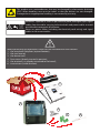
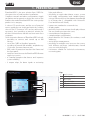
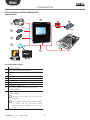
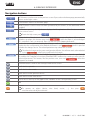
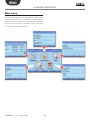
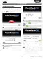
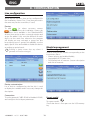
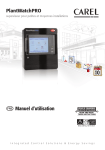
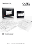
PlantWatchPRO supervisor for small-medium installations 30/06/20 06 i 30/06/2 /2006 30/06 /2006 30/06/20 06 30/06 /2006 X i i /2006 30/06 i i X i 2006 2006 /2006 i 006 30/06/ 30/06 30/06 i 006 30/06/2 30/06/ X 16:36:16 16:36:1 6 16:36:1 6 16:36:1 6 16:36:16 16:36:16 16:36:16 16:36 :16 16:36 :16 16:36:16 16:36:16 i i i i User manual LEGGI E CONSERVA QUESTE ISTRUZIONI READ AND SAVE THESE INSTRUCTIONS NO POWER & SIGNAL CABLES TOGETHER READ CAREFULLY IN THE TEXT! Integrated Control Solutions & Energy Savings ENG Content 1. presentation 5 2. KEY 7 3. installation requirements 7 4. assembly procedure 8 Concluded alarms............................................................32 Events..................................................................................32 Relays..................................................................................32 Download alarms.............................................................32 How to respond to alarm signals from PlantWatchPRO........................................................................33 12. scheduler Assembly..............................................................................8 5. board and connections 12 6. GRAPHIC INTERFACE 14 I/O configuration..............................................................35 Phone book.......................................................................35 Rule configuration............................................................35 I/O test................................................................................36 Guardian............................................................................37 Display................................................................................14 Touchscreen keypad........................................................14 Navigation buttons..........................................................15 Main menu........................................................................16 7. start up How to set scheduled rules ...............................39 How to configure the Guardian program .....43 17 How to configure email.......................................44 Configuration wizard....................................................... 17 8. CONFIGURATION 13. use of the usb memory key 18 How to update the PlantWatchPRO software using a USB memory key . ..........................................47 14. NAVIGATION VIA WEB FROM A REMOTE PC 48 PlantWatchPRO from a remote PC via a telephone connection.........................................................................48 How to configure a simple line..........................24 How to differentiate a device (or a group of devices) from the standard............................................27 28 10. reports 30 45 How to download an HACCP report from PlantWatchPRO ...........................................................46 Line configuration............................................................18 Model management........................................................18 Site information................................................................19 Users...................................................................................20 Floating suction................................................................20 System pages....................................................................20 Network configuration....................................................21 9. installation 35 15. function tree 50 16. TECHNICAL SPECIFICATIONS 52 Configure report...............................................................30 Export report.....................................................................30 Print report........................................................................30 Display data log................................................................30 11. alarms/eventS 32 Active alarms.....................................................................32 3 +040000021 - rel. 2.1 - 03.07.2009 This product uses semiconductors that may be damaged by electrostatic discharge (ESD). When handling, care must be taken so that the devices are not damaged. Damage due to inappropriate handling is not covered by warranty. NO POWER & SIGNAL CABLES TOGETHER READ CAREFULLY IN THE TEXT! WARNING: separate as much as possible the probe and digital input signal cables from the cables carrying inductive loads and power cables to avoid possible electromagnetic disturbance. Never run power cables (including the electrical panel wiring) and signal cables in the same conduits. Before performing any operations, check that the PlantWatchPRO box contains: 1. the two plastic faceplates (top and bottom); 2. the user manual; 3. the device itself; 4. four screws (already inserted in position); 5. the terminals (six, already connected to the board); 6. two resistors (inside the case). 1 2 3 4 5 6 ENG 1. presentation PlantWatchPRO is the new solution from CAREL for the supervision of small-medium installations. Complete network and alarm configuration, simple navigation and an attractive design are some of the features that make PlantWatchPRO the cutting edge product in its category. A colour LCD touchscreen, and the use of practical menus, guide the user simply and intuitively, without the use of a PC (however a PC can be connected if necessary), thus providing a practical solution for all those environments that do not have room for a computer. Other innovative features of PlantWatchPRO include: • possibility to connect and control up to 100 devices; • use of the CAREL or Modbus® protocols; • recording of around 100 variables, sampled every 15 minutes, for more than one year; • IP65 index of protection between the frame and the front panel; • ready for connection to the PlantVisorPRO Remote supervisor system; • a Guardian program that boosts and improves system reliability; • 3 output relays, for alarm signals or activating lights and defrosts; • possibility to export data (alarms, events, system • • • • • • • • • and model configurations and variable reports) using a USB memory key (the data are downloaded in a format that is compatible with Microsoft® Excel and Microsoft® Word); import new standard or custom devices; display graphs; proximity sensor that activates the display without the user needing to open the cover; external buzzer management; complete alarm configuration; phone book for SMS contacts, fax numbers, e-mail addresses; active defrost management; possibility for multiple users to access the system, with different privileges (administrator, normal user, user with privileges); instrument suitable for technical environments, no moving parts. Key: 1 touch screen 2 proximity sensor 3 alarm light 4 device on light 5 USB port 6 transparent cover 1 2 3 4 5 6 5 +040000021 - rel. 2.1 - 03.07.2009 ENG 1. prEsENtatioN General diagram of PlantWatchPRO connections 1 10 9 2 PSTN GSM/GPRS 3 4 5 LAN 7 8 6 Remote - Internet Explorer 7.0 Key and product codes: 1 2 3 PlantWatchPRO PostScript-enabled USB printer PSTN analogue modem (version PWPROM0000 only) 4 USB memory key 5 PC (via LAN) 6 3 relay outputs 7 Installation: Modbus® RTU line 8 Installation: CAREL line 9 GSM/GPRS modem connection kit(code PWOPMD0000) 10 optional GSM/GPRS modem (code PLWOPGSM00) required to be able to use all the SMS functions; using modems other than the one supplied by CAREL will not guarantee correct operation of the appliance and technical service +040000021 - rel. 2.1 - 03.07.2009 6 ENG 2. KEY note highlights an important point; in particular as regards the practical use of the various product functions warning warns the user of critical areas for the use and safety of PlantWatchPRO USB key indicates that the function can only be accessed directly from PlantWatchPRO (not via web) and using a USB memory key tutorial offers the user some simple configuration examples of the most common settings for the supervision of an installation 3. installation requirements The following are required to install PlantWatchPRO: oo two screwdrivers, one Phillips-head and the other flat-head; oo a drill to make the holes required on the frame of PlantWatchPRO; oo screws for mounting the unit on the wall; oo step bit max. dia. 32 mm. In addition Before performing any operation, check that the PlantWatchPRO box contains: oo the device itself; oo the two plastic faceplates (top and bottom); oo the terminals (six, already connected to the board); oo four screws (already inserted in position) oo two resistors (inside the case); oo the user manual. 7 +040000021 - rel. 2.1 - 03.07.2009 ENG 4. assEmblY procEdurE assembly Remove PlantWatchPRO from the plastic bag it is wrapped in and place it on the bench. To safeguard operators and the boards, disconnect power before performing any operations. Electrical damage may occur to the electronic components as a result of electrostatic discharges from the operator. Suitable precautions must be therefore be taken when handling these components. Open PlantWatchPRO from right to left (side hinged by the yellow clamps), making sure not to disconnect the ribbon cable from the display (a) and the other cable that connects to the board from the front panel (b). Warning: • disconnect power before handling the product; • avoid touching or nearly touching the electronic components fitted on the boards, so as to avoid electrostatic discharges (extremely dangerous) from the operator to the components; • the materials must be kept inside their original package as long as possible. • absolutely avoid non-antistatic plastic bags, polystyrene or sponges; • never not pass the boards directly between operators (to prevent from electrostatic induction and discharges). • using a different power supply from the one specified may seriously damage the system; • connection errors (and connections other than those specified in this manual) may endanger the safety of the users and cause faults to the instruments and the components connected; • Fit a cutout device outside of the appliance connected in series with the power supply: Carel requires the use of a slow-blow fuse with a rated current of 1.25 A. The cutout device must be rated to protect the product against temporary voltage surges higher than the maximum continuous voltage, thermal overload due to leakage current, fire and explosion in the event of short-circuits. • Fit one or more disconnect switches outside of the appliance in an easily accessible position, to disconnect the product form the mains power supply If using the PlantWatchPRO version with predrilled frame (code PWPROxxxxxxxx), start assembly procedure from point . +040000021 - rel. 2.1 - 03.07.2009 8 ENG 4. assEmblY procEdurE Remove the board using a flat-head screwdriver, levering the two tabs (3a and 3b) on the grill that secures it in place; then fully place the board on the front part of PlantWatchPRO (3.c). Now drill the plastic frame of PlantWatchPRO to make the opening for the connection cables, holding it firmly by hand, as shown in the figure. Warning: drill PlantWatchPRO using a step bit with a maximum diameter of 32 mm. 3a 3b Then place the board in position and press until the locking tabs on the grill click into place. 3c 9 +040000021 - rel. 2.1 - 03.07.2009 ENG 4. assEmblY procEdurE Using the drilling template (provided on the box), drill the wall where PlantWatchPRO is to be mounted, and then fasten it to the wall using four screws. Once PlantWatchPRO has been fastened to the wall, and the cables have been run through the holes in the frame, the wiring can be completed, as shown in chapter 5 "Board and connections". 218.5 www.carel.com 162.5 www.carel.com 2 Warning: to ensure the index of protection, the screws used to fasten PlantWatchPRO to the wall must only pass through the four existing holes in the four corners of the frame. +040000021 - rel. 2.1 - 03.07.2009 10 1 www.carel.com 1 218.5 162.5 ENG 4. assEmblY procEdurE Once wiring has been completed, close PlantWatchPRO again, making sure the two tabs click into the corresponding slots. Finally, fit the top and bottom plastic faceplates, by lightly pressing them into place. Then fasten the front to the rear using the four screws supplied. Warning: to ensure the IP65 index of protection, the rubber gasket must be correctly positioned between the two parts of the PlantWatchPRO frame. Warning: if during the assembly operations the display cable is detached from terminal JZIF1, proceed as follows to connect it again: • lift the “clip-clap” tab on the terminal; • connect the display cable, holding it in place with two fingers; •finallylowerthetabontheterminaluntilitclicks into place, thus securing the cable. 11 +040000021 - rel. 2.1 - 03.07.2009 ENG 5. board and connections • Front USB: only use standard USB cable, less than Wiring 3 m long. To safeguard operators and the boards, disconnect power before performing any operations. Electrical damage may occur to the electronic components as a result of electrostatic discharges from the operator. Suitable precautions must be therefore be taken when handling these components. CAREL recommends the following wiring: • in the right opening the RS485 (JP11 and JP12), modem (JP14), Ethernet (JP22), USB (JP20) and telephone lines (JP15); • in the left opening the power (JP10) and relay cables (JP3, JP5 and JP6). Complete the connections, as follows: • plug the telephone line into connector JP15; • connect the lines for the devices in the installation to terminals JP11 & JP12 (line 1 to JP11 and line 2 to JP12) (RS485 serial interface)(*); • connect the three relays to terminals JP3, JP5 and JP6; • JP13 is the terminal for the RS232 serial interface, reserved for the service connections; • JP14 is the terminal for the RS232 serial interface, used to connect a GSM/GPRS modem (optional); Use cables with a max. length of 30 m • plug the network cable (for LAN connection) into the Ethernet connector JP22(**). • connect the optional USB device to JP20 (***); • finally connect the power cable to terminal JP10. Warning (*) RS485 line: • observe the polarity (+.-,GND); • the maximum length must not exceed 1000 m. • do not make branches in the line or star connections; • the most distant terminal must be fitted with a 120 Ohm ¼ W resistor (included with the product) between + and - ; • avoid laying the line near power cables; • use shielded cable and connect the shield to the GND pole only. CAREL recommends Belden cables code 8761.8762 or equivalent. Ethernet: (**) (***) • use shielded cable Cat.5e SFTP USB: • only use standard USB cable, less than 30 m long: to ensure correct operation of the USB connection, CAREL recommends cables no longer than 5 m; for longer cables, signal repeater devices should be used; +040000021 - rel. 2.1 - 03.07.2009 12 ENG 5. board and connections Terminals and connections: JP3 relay 1 JP5 relay 2 JP6 relay 3 JP15 telephone line JP10 power supply JP12 RS485 (field - line 2) JP11 RS485 (field - line 1) JP14 RS232 (optional GSM/GPRS modem) JP13 RS232 (service) JP22 Ethernet (LAN) JP20 USB N L J P10 Input: 110-240 V ~ 50/60 Hz Max current: 150 mA N.O J P6 N.C Relay 3 COM J P5 N.O J P3 N.O Relay 2 COM Relay 1 COM J P12 - + RS485 L ine 2 GND Warning: the RESET procedure is reserved for qualified personnel only J P11 - + RS485 L ine 1 GND J P15 J P14 Phone line RS232 M odem J P13 RS232 Serv ic e J P22 RESET 13 J P20 +040000021 - rel. 2.1 - 03.07.2009 ENG 6. GrapHic iNtErFacE display touchscreen keypad The following keypad will be made available on the touchscreen display whenever data needs to be entered (letters, numbers or symbols): One of the main features of PlantWatchPRO is the user interface. Web navigation also uses the same graphic interface, identical to the touchscreen except for some functions that can only be accessed directly from PlantWatchPRO using a USB memory key (these are highlighted in the text by ). USB To switch from the main keypad (upper case) to the other keypads, use the following buttons: USB to shift to lower case for the numeric keypad for symbols and punctuation +040000021 - rel. 2.1 - 03.07.2009 14 ENG 6. GRAPHIC INTERFACE Navigation buttons BACK button: used to return to the previous screen. If pressed on the home page, automatically returns to the login screen HOME button: returns to the home page SILENCE button: used to mute the alarm generated by the buzzer (or the additional siren, if installed) HELP button: pressing the Help button displays a brief explanation of the functions available in the current screen To exit the Help screen, press displays the list of the devices in the installation and the corresponding alarms. When a device generates an alarm, this button turns red ( ) until the alarm is acknowledged -PV-, cancelled -Canc.- or removed -Rem.- by the user (see chapter dedicated). restarts the system software, loading the changes made to the configuration; if the changes require the new configuration to be loaded, the button is red ( ) until it is pressed to make the changes active. The reload operation may take a few seconds. To make the changes to the system configuration effective, the software needs to be reloaded (using ), after having confirmed the changes opens the window for setting the “Guardian” program; the notification channels specified will be used by the “Guardian” to send any PlantWatchPRO malfunction warnings to the specific technical personnel. This button, like the previous two, turns red ( ) when the program is activated CONFIRM button: confirms the changes made to the screen scrolls the list upwards scrolls the list downwards scrolls the list to the previous device scrolls the list to the next device used to access the key to the graph of the variables on the corresponding screen add remove To remove an object (device, time band, action, …), first press and then select the object to remove 15 +040000021 - rel. 2.1 - 03.07.2009 ENG 6. GrapHic iNtErFacE main menu The PlantWatchPRO main menu features the clock, the navigation buttons, the information on the name of the site, and five icons: Installation, Configuration, Reports, Alarms/Events and Scheduler; pressing each of these accesses other secondary menus with the lists of corresponding functions. +040000021 - rel. 2.1 - 03.07.2009 16 ENG 7. start up configuration wizard When PlantWatchPRO is first started, the following presentation screen will be displayed Pressing accesses the page for selecting the LANGUAGE and the TIMEZONE. As the final phase in the program initialisation process, the previous selections need to be confirmed by pressing the button or going back (with the button) and changing the settings. Warning: check the settings carefully before pressing as once confirmed, the other languages and time zones can no longer be recovered. Press the corresponding fields to select the desired items from the lists. The selection is confirmed by moving to the following screen ( button) A confirmation message then notifies the user that the settings have been saved and, once the system has been rebooted, the PlantWatchPRO main menu will be accessed. Now enter the date and time by selecting the corresponding fields. Warning: the following default values are used whenfirstloggingin:USER:“Admin”PASSWORD empty; once having logged in, it is recommended to immediately change the Admin user password and keep it in a safe place: losing this information may compromise access to the system The date format is “yyyy/mm/dd” and the time formatis“hh/mm”. 17 +040000021 - rel. 2.1 - 03.07.2009 ENG 8. coNFiGuratioN line configuration Line 1 and Line 2 (these are the two lines that can be configured for the installation: choose “line 1” and then proceed in the same way for the second line, if used). Devices To add (or where necessary remove ) devices to/from the installation, choose the type (from those available in the PlantWatchPRO archive), then assign a short custom description and assign the address (this must be different for each device on the same line, otherwise the program will display an error message); a group can also be assigned (up to 5 groups are available), used to apply specific rules and enable or disable the device according to special needs. Disabling a device means that any alarms it generates will not be managed. model management Model configuration Used to configure the models corresponding to the instruments, that is: • Alarms (priority and enable/disable); • Log/graph/HACCP/main view; • Description/unit of measure (custom description and unit of measure). Device customisation List of devices configured on the line; this is used to display the variables and if necessary change the description. Connection Export model To set the protocol (CAREL-RS485 or Modbus®-RS485) and configure the serial port parameters. USB USB +040000021 - rel. 2.1 - 03.07.2009 18 To export models . Check that there is free space on the USB memory key. ENG 8. coNFiGuratioN Import model Remove model The following models of devices can be imported: • standard models (downloaded from http://ksa. carel.com); • models exported from PlantWatchPRO; • models created or modified using Device Creator. To remove a model that is not used by the installation and thus free up part of the PlantWatchPRO memory. To import a standard model (e.g.: newstandardmodel), download the .zip file from http://ksa.carel.com and unzip the file into the main directory of a USB pen drive. At the end of the procedure, make sure that the "\models\standard\newstandardmodel\" path has been created on the USB pen drive. site information This is used to enter the information relating to the site where PlantWatchPRO is installed, plus some information on technical service for support in the event of problems. The text entered in the MAINTENANCE TECH. and TELEPHONE fields will be displayed when pressing the button from the login screen, so as to indicate who to contact in the event of need. The PASSWORD IDENT and CONFIRM (password) fields must be completed if a password needs to be set for the connection to PlantWatchPRO Remote. To import a model exported from PlantWatchPRO (e.g.: IR33) make sure the .xml the file is placed on the USB pen drive in "\export\sitename\models\IR33. xml". (sitename is the name of the site set on the Configuration -> Site information page in the PlantWatchPRO that the model was exported from; if the model is exported directly to the USB pen drive, the path is created automatically). To import a model created or modified using Device Creator (e.g.: mymodel.xml) make sure the .xml the file is placed on the USB pen drive in "export\ mydirectory\models\mymodel.xml. (mydirectory can be any name). Important: if the Device Creator version is lower than 3.0 the .xml file must be located in \models\dcreator\mymodel.xml Important: if importing an existing model, some of the data will be overwritten. Copy model Used to create new models based on an existing model, then making the desired changes. Updating the model used as the basis for others also changes all the models derived using the copy function. 19 +040000021 - rel. 2.1 - 03.07.2009 ENG 8. coNFiGuratioN users system pages Administrator Reload configuration Used to modify the password for the administrator user. This is the function that makes the changes made to the previous configuration effective. No changes to the system will be active unless the button is pressed, which remains red ( ) as a reminder, while the system is still in the previous configuration. Only after having confirmed the changes on the reload page will the system be updated. Normal user Used to create new users and assign them different privileges (site configuration/change parameters/ alarm management). Backup/Restore Backup site configuration Once an installation has been configured, the configuration can be saved and exported and then used to configure another PlantWatchPRO. Operation also available via web Restore site configuration Import the system configuration from a USB key Remote service . USB Used to configure the user for remote service. For system security, the remote service user is normally USB when remote disabled and should be only enabled service is required. Floating suction Used to configure and activate the floating suction pressure control function. Rack 1 (or 2) Information For details on the operating status and information on the showcases and compressor racks. Update software To update the PlantWatchPRO software, see Chap. Configuration "13. Use of the USB memory key" To configure the compressor racks, set the connected showcases, the main parameters for the floating suction pressure control function algorithm and reset the algorithm calculation period for one or more showcases. +040000021 - rel. 2.1 - 03.07.2009 USB USB 20 . ENG 8. coNFiGuratioN Display/Clock Control panel for the date/time and display settings. Network configuration Configuration of the network settings for the local network (LAN) connection. By default, the USE DHCP item is selected, which allows the system to detect the network settings automatically. The network settings should only be configured manually by qualified personnel. 21 +040000021 - rel. 2.1 - 03.07.2009 ENG 8. CONFIGURATION Tree of the “Configuration” menu functions Line config. Line 1/2 Device list Device customisation Connection Model management Site info Model configuration Alarms Import standard models Log/graph/HACCP/main view Export model Description unit of measure Import model Copy model Remove model Users Administrator Remote user Floating Suction Normal user List of normal users Rack 1/2 Information Configuration System pages Reload configuration. Backup/restore Backup site configuration Update software Restore site configuration Display/ clock Network configuration +040000021 - rel. 2.1 - 03.07.2009 22 ENG 8. CONFIGURATION Device detail List of variables Variable detail List of device models List of alarms List of device models List of variables List of device models List of variables Normal user details Rack Rack detail Showcases List of showcases Showcase detail List of showcases Showcase detail Rack Showcases Parameters Reset 23 +040000021 - rel. 2.1 - 03.07.2009 ENG 8. coNFiGuratioN How to configure a simple line First of all, the user needs to configure PlantWatchPRO in relation to the devices in the specific installation. From the home page, enter the menu CONFIGURATION LINE CONFIGURATION LINE 1 DEVICES menu. Progressively add all the devices featured in the installation and connected to line 1, assigning a specific description, an address and if necessary add the device to a group (up to five groups are available) for applying one or more rules (see the part of the manual corresponding to the SCHEDULER menu). Each device on the same line must have a different address from the others, otherwise, if the same address is assigned twice, an error message will be displayed. After having entered the devices, go back and DEVICE CUSTOMISATION press the LINE 1 item. Here the name of each individual device and each related variable can be customised. Go back and choose the type of CONNECTION, from the standard protocols proposed, the connection speed (BAUD RATE), the number of DATA BITS, the PARITY and the number of STOP BITS. Repeat 1, 2 & 3 for LINE 2 (if used). +040000021 - rel. 2.1 - 03.07.2009 24 ENG 8. coNFiGuratioN Entering MODEL MANAGEMENT MODEL CONFIGURATION ALARMS and choosing the devices on the two lines from the list one at a time, the alarms can be enabled or disabled and the priority set (the priority of an alarm will be indicated in the list with a different colour, depending on the level). Then return to the previous menu and enter LOG/GRAPH/HACCP/MAIN VIEW DEVICE DETAIL VARIABLE DETAIL ; a screen will be displayed for selecting: the frequency for recording the value of the variable, the colour used to draw the curve showing the trend of this variable on the graph, and if required include the variable in the report and/or on the graph. In the list of variables logged, the columns have the following meanings: Freq: sampling frequency. G: variable displayed on the graph. P: variable included in the HACCP report. M: variable included in the main list of devices in the installation (INSTALLATION menu). The data recording period depends on the sample time, as shown in the table below: Sampling time 30 s 1 min 3 min 5 min 15 min Recording period 13 days 26 days 80 days 133 days 400 days 25 +040000021 - rel. 2.1 - 03.07.2009 ENG 8. coNFiGuratioN DESCRIPTION/UNIT OF MEASURE is used to change the name and unit of measure of the variables. Reload the configuration, using the button and the dedicated screen. The line is thus configured, and from the INSTALLATION menu all the settings defined thus far can be displayed under CONFIGURATION. +040000021 - rel. 2.1 - 03.07.2009 26 ENG 8. coNFiGuratioN How to differentiate a device (or a group of devices) from the standard An example of how to create another model of device with other features starting from the IR33 From the home page, enter the CONFIGURATION MODEL MANAGEMENT COPY MODELS menu, from the ORIGINAL MODEL list choose the standard model to start from (in the example, “IR33”) and in the field TARGET MODEL field enter the name to be given to the new model (in the example, the new model has been called “IR33modificato”) The model created is now identical to the one used as the starting point. Return to the MODEL MANAGEMENT MODEL CONFIGURATION menu to customise the new devices created, changing the settings relating to: • ALARMS; • LOG/GRAPH/REPORTS; • DESCRIPTION/UNIT OF MEASURE. A model can thus be created that is different from the one used as the starting point, based on specific needs. After having created the new model with different features from the standard IR33, these types of devices can be installed, following the first steps in the sequence of operations presented in the TUTORIAL on the configuration of a simple line. 27 +040000021 - rel. 2.1 - 03.07.2009 ENG 9. iNstallatioN Group 3 - Control When entering this menu a list is displayed showing all the devices available in the installation and their status: the graphic LEDs next to the names of the devices have the following meanings: • green - everything is working correctly. • red - the device has an alarm. • blue - device disabled. • grey - device off-line. In addition, the main variables previously selected to MODEL be displayed (from the CONFIGURATION MANAGEMENT CONFIGURATION MODELS LOG/GRAPH/HACCP/MAIN VIEW DEVICE DETAIL menu) are shown, or alternatively the default variables and the corresponding values. Accessing the detail of each device, the alarms can be acknowledged (both concluded and active) and the graph of the trend of the variables displayed. Displays the list of system clock parameters. Other groups Group 4 – Device configuration Displays the list of parameters relating to the configuration of the device in question. Group 5 - Functions Displays the list of parameters relating to the functions. Active alarms Goes to the list of active alarms (see Chapter 11 ALARMS/EVENTS). Concluded alarms Goes to the list of concluded alarms (see Chapter 11 ALARMS/EVENTS). Graph Graph of the variables. The horizontal axis shows the time scale, while the vertical axis shows the values of the variable. (The colours have been set previously by the user in the CONFIGURATION menu). use the & buttons to scroll the time & buttons to move axis and the from one device to another. PlantWatchPRO can plot up to five values at the same time. Read-only variables Favourites Displays the variables set as favourites. All variables Displays all the variables. Write parameters Favourites Displays the parameters set as favourites. All parameters Displays all the parameters. Group 1 – Alarm configuration Displays the list of alarm configuration parameters. Group 2 – Control Displays the list of control parameters. +040000021 - rel. 2.1 - 03.07.2009 28 ENG 9. iNstallatioN Search To search for variables or parameters based on parts of the description or code. Tree of the “Installation” menu functions Device list Read-only variables Favourites List Details All List Details Write parameters Favourites List Details All List Details GR1 List Details GR2 List Details GR3 List Details Other grps GR4 List Details GR5 List Details Active alarms List Details Concluded alarms List Details Graph Search Read-only variables Write par. 29 +040000021 - rel. 2.1 - 03.07.2009 ENG 10. rEports configure report Export report Create report Export HACCP report Used to create a report, defining the name and description, the type (HACCP) and the list of the variables included. Used to enter the values of the parameters (starting date, report name, period and frequency) corresponding to the HACCP report to be downloaded. Export log report Used to enter the values of the parameters (starting date, report name and period) corresponding to the log report to be downloaded. print report Print HACCP report Used to enter the values of the parameters (starting date, report name, period and frequency) corresponding to the HACCP report to be printed. If the report is defined as HACCP, it may only include the HACCP variables for the devices in the installation. The definition of the device HACCP variables can be customised under Model configuration. Print log report Used to enter the values of the parameters (starting date, report name and period) corresponding to the log report to be printed. Edit report Edit description PlantWatchPRO is compatible with any USB printer that supports PostScript language. To modify the description of the report. Via web, PlantWatchPRO opens a dialogue box prompting for the directory used to save the HACCP report ( “.rtf” format, compatible with Microsoft® Word) or log report (“.csv” format, compatible with Microsoft® Excel). Edit configuration To modify the list of the variables in the report. Copy report To generate a new report starting from an existing report. display data log Delete report Directly displays the values of the logged variables. To delete the report. +040000021 - rel. 2.1 - 03.07.2009 30 ENG 10. REPORTs Tree of the “Reports” menu functions Configure report Create report Edit report Copy report Delete report Export report List of reports Export HACCP report Export log report Print report Print HACCP report Print log report Display data log 31 +040000021 - rel. 2.1 - 03.07.2009 ENG 11. alarms/EVENts active alarms If the message in the EVENT column is too long to be displayed in full, to read it select the corresponding row and open the details Displays the active alarms on the system; key to alarm colours: • red - highest priority; • orange - high priority; • yellow - medium priority; • white - low priority. relays Used to disable the relays activated by PlantWatchPRO. Pressing the corresponding fields and confirming ) disables the relays. ( download alarms This saves the list of active alarms from a certain date onwards; the data is saved to a file in “.csv” format (compatible with Microsoft® Excel). concluded alarms Shows the list of concluded alarms. Events Tree of the “Alarms/events” menu functions” List of the events saved by the system. The icons have the following meanings: Active alarms information event Conc. alarms error event Events warning event Relays Down. alarms +040000021 - rel. 2.1 - 03.07.2009 32 Alarm details Event details ENG 11. alarms/EVENts How to respond to alarm signals from plantWatchpro Below is a description of how alarms are shown on the PlantWatchPRO display and how to respond. If the ALARM button turns red ( ) an alarm is active on one of the field devices. Enter ALARMS/EVENTS ACTIVE ALARMS to display the list of active alarms in the entire installation, highlighted in four different colours depending on the level of priority: • red - highest; • orange - high; • yellow - medium; • white - low. In the example, a low priority alarm called “Al.timeoutdefrostevap2”isactivatedon thedevicecalled“IR33#1”. From the list of active alarms, pressing the row showing the alarm in question accesses the page with the details of the alarm. This highlights the date and the time when the alarm was activated, plus three fields (PV, CANC. and REM.) that are empty if the page is being accessed for the first time. Abbreviations: PV - PV - acknowledge alarm; Canc. - cancel alarm, that is, all the actions relating to the alarm are cancelled (e.g. send SMS, fax,…) before being undertaken by PlantWatchPRO; Rem. - remove alarm from the list of active alarms. Pressing the button PlantWatchPRO records the user who performed the operation as the person acknowledging the alarm; in addition, the date and the time when the operation was performed are also recorded. 33 +040000021 - rel. 2.1 - 03.07.2009 ENG 11. allarmi/EVENti Pressing the button again records the time and date the alarm was cancelled and who performed the operation; this may be a different user from the one who previously acknowledged the alarm. Pressing a third time records the identity of the user who removed the alarm on PlantWatchPRO. Once the alarm has been removed, it no longer appears in the list of ACTIVE ALARMS, but rather can be seen in another screen with the list of CONCLUDED ALARMS. Once the alarm has been cancelled, the button turns blue again. Pressing the row with the desired alarm again opens the detail screen, showing the date, time and name of the user who acknowledged, cancelled and removed the alarm. +040000021 - rel. 2.1 - 03.07.2009 34 ENG 12. scHEdulEr i/o configuration phone book This menu is used to configure the number of attempts at an alarm signal (if the previous was not successful) and the interval between the one attempt and the next at the following signals: • fax; • SMS; • e-mail; • PlantVisorPROremote. Up to five fax recipients, five SMS numbers, five e-mail addresses and one remote access connection can be configured. Each recipient may have more than one number or address, separated by semi-colons (;),as in the most commonly used e-mail programs What is a rule? For each alarm or group of alarms (including from different devices), a series of rules can be defined, which may be: As regards the e-mail addresses, the data relating to the server and the Dial-Up connection can be simply and intuitively configured on PlantWatchPRO. In addition, the procedure and time for resetting the buzzer and the three relays can also be set. • a set of actions (fax, SMS, e-mail, print, activate relay, buzzer, remote access); • a time band; • a delay. If an alarm goes off, the actions are performed. If a delay is set, the actions are performed after having waited the time set for the delay. If the time band is set, the actions are only performed if the alarm is activated within the time band. rule configuration Time bands Used to enter time bands for implementing the rules; the DAILY/WEEKLY/SPECIAL EVENT submenu can be used to add or remove time bands of different durations that can be completely customised by the user. 35 +040000021 - rel. 2.1 - 03.07.2009 ENG 12. scHEdulEr Actions Notifications For correct data entry, first create the time bands and the actions. Configuration of the parameters for the notifications and the activation of the alarm channels. Scheduled rules Display the list of scheduled rules; scheduled rules can be added/removed or edited, pressing the detail of the rule to open the special menu for setting the configuration parameters. Scheduled activities List of the scheduled activities; the parameters controlling the various activities can be set, where necessary assigning them to a certain group of devices (set during the configuration procedure). Sign of life: this function can be used to enter a scheduled command that sends a sign of life (notification action) via one of the channels available Reports Used to create and set a new scheduled action that sends a report by e-mail and/or prints a hard copy. i/o test Test the correct operation of the Input/Output channels. Rules Display the list of rules for notifying the alarms; rules can be added/removed or edited, pressing the detail of the rule to open the special menu for setting the configuration parameters. +040000021 - rel. 2.1 - 03.07.2009 36 ENG 12. scHEdulEr Guardian Notifications Configuration of the notification parameters for the “Guardian” program; the channels set are used by the “Guardian” to send notifications of any malfunctions on PlantWatchPRO to the technical personnel indicated. Alarm priority Used to configure the priority of the alarms, entering the settings in the respective fields. If the type of the alarm is selected, the “Guardian” program checks that the alarm is managed within the maximum time specified in the field. If this is not the case, notification is sent via the channels configured in the NOTIFICATIONS menu. 37 +040000021 - rel. 2.1 - 03.07.2009 ENG 12. SCHEDULER Tree of the “Scheduler” menu functions I/O config. Fax config. SMS config. Phone book E-mail config. e-mail Remote config. Dial-up Network config. Relay details Fax Sms E-mail Rile config. Remote access service Daily Daily details Time bands Weekly Weekly details Special event Special event details Notifications Notification details Scheduled activities Scheduled activity details Reports Report details Actions Rules Rule details Scheduled rules Scheduled rule details I/O test Guardian Notifications Priority +040000021 - rel. 2.1 - 03.07.2009 38 ENG 12. scHEdulEr How to set scheduled rules Below is a step-by-step description of how to turn off the lights at 20:00 each working day and turn them on again in the morning at 9:00. From the home page, enter the SCHEDULER RULE CONFIGURATION TIME BANDS DAILY menu: enter the daily time bands for switching the light off or on; in the example two time bands have been created, called “working day” “(09:00-20:00)“ and “working night” “(20:01-08:59)”. To set the night-time band “21:00-06:00”, itmustbedividedintotwobands:“21:0023:59”and“00:00-06:00”. From the TIME BANDS WEEKLY menu: now create the weekly light On/Off time bands; in the example two bands have been created relating to day and night (day= lights on, night= lights off ), called “working week day” and “working week night”, entering first the daily time bands created previously on the days from Monday to Friday (premises considered closed Saturday & Sunday). 39 +040000021 - rel. 2.1 - 03.07.2009 ENG 12. scHEdulEr Return to the RULE CONFIGURATION ACTIONS SCHEDULED ACTIVITIES menu: enter the desired actions (on the entire installation or just on some devices, using the option for assigning the actions to the GROUPS). Two actions have been created, “lights ON” and “lights OFF”, turning the lights on and off respectively Then go to RULE CONFIGURATION SCHEDULED RULES : enter the new scheduled rules, that is, one that acts in the time band when the lights should be on, activating the action that switches the lights on (this rule will be called “lights on (day)”) together with another rule that switches the lights off, thus activating the “lights OFF” action (this rule has been called “lights off (night)”. In four steps, a scheduled activity has been set that automatically switches the lights on and off ; the same procedure can be used to create other rules acting on the installation (entire installation or just some devices. +040000021 - rel. 2.1 - 03.07.2009 40 ENG 12. scHEdulEr How to set the rules Below is a description of how to set PlantWatchPRO to notify a highest priority alarm activated in the night-time time band (21:00-08:00) via SMS. From the home page, enter the SCHEDULER RULE CONFIGURATION TIME BANDS DAILY menu: create a time band that goes from 21:00 to 08:00; in the example this has been called “night”. Remember that to set the night-time band “21:00-08:00”itmustbedividedinto“21:0023:59”“00:00-08:00”. Return to TIME BANDS WEEKLY : create a weekly time band in which the “night” daily band is applied every day of the week; this weekly time band has been called “every night”. Return to the RULE CONFIGURATION ACTIONS NOTIFICATIONS menu: enter the notification action “send SMS”, selecting from the SMS list the telephone number of “maintenance tech. X” to send the SMS to as the only notification channel. 41 +040000021 - rel. 2.1 - 03.07.2009 ENG 12. scHEdulEr Return to the RULE CONFIGURATION RULES menu: now create a rule (called “night SMS”), applying a DELAY of one minute (enter “1” in the corresponding field); from ALARM PRIORITY choose “Highest”, from TIME BANDS, “every night” (band previously created in the corresponding menu) and finally, from ACTION “send SMS”. With these settings, as soon as a highest priority alarm is activated, on any night of the week, PlantWatchPRO waits one minute and, if within this time interval the alarm has not concluded, notification of a highest priority alarm will be sent via SMS to “maintenance tech. X". +040000021 - rel. 2.1 - 03.07.2009 42 ENG 12. scHEdulEr How to configure the Guardian program Below is a description of how to send a fax to a certain number if a highest priority alarm is activated on a field device. From the home page, enter the SCHEDULER PHONE BOOK FAX menu, and enter the fax number to send the notification to, with a short description Return to the SCHEDULER and enter the GUARDIAN NOTIFICATIONS menu, choose the fax number set previously in the PHONE BOOK from the list. Return to the GUARDIAN and enter the ALARM PRIORITY menu, select the type of alarm to be managed using the Guardian program; in this case select “Highest”, to have the alarms with the highest priority signalled via fax if the system does not manage them within 30 minutes (“30 min” is the time set by the user). 43 +040000021 - rel. 2.1 - 03.07.2009 ENG How to configure email Below is a step-by-step description of how to configure the parameters to allow PlantWatchPRO to send email. From the home page enter the SCHEDULER I/O CONFIGURATION E-MAIL CONFIGURATION E-MAIL menu to access the parameter configuration screen Under SENDER enter the e-mail address of the sender of the e-mail The USER, PASSWORD and SMTP fields should be completed with the data supplied by the ISP. Warning: the IP address, and not the URL, must be entered in the SMTP field. This configuration should be completed by qualified personnel (systems administrators) Then enter the NUMBER OF ATTEMPTS to be made and the delay between attempts (RETRY AFTER __ MINUTES field) Under TYPE choose whether to access via LAN or via modem (Provider) If accessing via modem (i.e. “Provider” has been chosen in the TYPE field), the Dial-Up also needs to be configured: From the home page enter theSCHEDULER I/O CONFIGURATION E-MAIL CONFIGURATION DIAL-UP menu and enter the telephone NUMBER to connect to when sending e-mail, the USERNAME and PASSWORD. Warning: the telephone NUMBER, USERNAME and PASSWORD used on the Dial-Up configuration page are supplied by the ISP After having completed these steps, make sure that the e-mail communication channel has been configured correctly, using the special function: from the home page go I/O TEST and choose the to SCHEDULER desired e-mail CHANNEL (e-mail address previously entered in SCHEDULER PHONE BOOK E-MAIL +040000021 - rel. 2.1 - 03.07.2009 44 ENG 13. usE oF tHE usb mEmorY KEY PlantWatchPRO can transfer data to/from a USB memory key; specifically, some functions are not accessible via web, but only using PlantWatchPRO. In fact, the user can download the logged values of the selected variables, the HACCP report, the configuration of the complete site, the changes made to various models (to be then exported to others sites for reuse) and the list of alarms activated in the installation. Function File path DOWNLOAD HACCP REPORT BACKUP SITE CONFIGURATION DOWNLOAD ALARMS EXPORT MODEL G:\export\site_name\ report G:\export\site_name\ config G:\export\site_name\ alarms G:\export\site_name\ models File format .rtf --.csv .xml The USB key must be formatted with the FAT32 file system. The USB memory key can also be used to load new data to the PlantWatchPRO memory; this is useful, for example, for importing the configuration of a previously configured site, models created based on the default models or those available in the standard libraries, or those created using the special Device Creator (IDE package). A USB memory key can also be used to install new updated versions of the PlantWatchPRO software. “G:\” is the name that usually denotes the removable memory drive on the PC, in this case, the USB memory key; “site_name” is the name that assigned to the directory where the files will be saved and is the name that the user has assigned to the site under CONFIGURATION SITE INFORMATION. The following functions are only accessible directly on PlantWatchPRO and only using the USB memory key (highlighted in the manual by • IMPORT MODEL; USB • RESTORE SITE CONFIGURATION; • UPDATE SOFTWARE. ): USB Other functions that require the USB memory key, if using PlantWatchPRO, yet are also accessible via web, are: • EXPORT LOG REPORT; • EXPORT HACCP REPORT; • BACKUP SITE CONFIGURATION; • EXPORT MODEL; • DOWNLOAD ALARMS. The table below shows a list of the functions that use the USB memory key to save data; the names of the directories (created automatically by the software) where the data are saved are listed (with the corresponding addresses), as well as the format the file is downloaded in. 45 +040000021 - rel. 2.1 - 03.07.2009 ENG 13. usE oF tHE usb mEmorY KEY How to download an Haccp report from plantWatchpro Below is a description of the operations to be performed by the user to download a HACCP report from PlantWatchPRO using the USB memory key, and then transfer the data to a PC. For example, download the daily report, with the data shown every 30 minutes, relating to 19 July 2007. From the home page, enter the REPORT EXPORT REPORT EXPORT HACCP REPORT menu. As the START DATE enter the day the report should start, therefore “2007/07/19”. Select “1 day” as the PERIOD. Insert the USB pendrive in the port. Choose “30 minutes” as the FREQUENCY (the other option for displaying the values of the HACCP variables is “12 hours”). Finally press the button and the OK button on the Warning message that appears to start the data transfer from PlantWatchPRO to the memory key. After a short while a message box is shown confirming the operation, or alternatively an error message if the memory key does not have enough space or has not been inserted correctly. +040000021 - rel. 2.1 - 03.07.2009 46 ENG www.carel.com 13. usE oF tHE usb mEmorY KEY How to update the plantWatchpro software using a usb memory key How to update the PlantWatchPRO software with new versions released by CAREL. Check the software version currently installed. The file downloaded will be a compressed file such as “Uxxxyyy.zip”. Unzip the file to the USB memory key. Download the software update from the http://ksa.carel.com website to the PC Uxxxyyy.zip USB From the PlantWatchPRO home page access CONFIGURATION SYSTEM PAGES UPDATE SOFTWARE. Insert the memory key and press the and the OK button on the Warning message that appears. From the list that will be displayed on the new screen, select the “patch” directory as the source for updating the software version. Press the button and the OK button on the Warning message that appears to start the software update operation.. After this operation, as highlighted by the Warning message, PlantWatchPRO will be rebooted to make the software update effective. This operation may take a few minutes. Warning: • never remove the USB memory key until the software update has been completed and the system has been rebooted, as both PlantWatchPRO and the key may be seriously damaged; • power must be available throughout the entire software update operation. 47 +040000021 - rel. 2.1 - 03.07.2009 ENG 14. NaViGatioN Via WEb From a rEmotE pc PlantWatchPRO installed in any location can be monitored via an internet or telephone connection. This function can be used to display on the PC’s screen the exact same data that appears on the PlantWatchPRO touchscreen display and access almost all the PlantWatchPRO functions. plantWatchpro from a remote pc via a telephone connection Once the PC is running, in Microsoft Windows (any version), from the Control panel create a new Internet connection, as follows: Access CONTROL PANEL INTERNET CONNECTIONS. Then choose CREATE A NEW CONNECTION CONNECT TO THE INTERNET SET UP MY CONNECTION MANUALLY CONNECT USING DIAL-UP MODEM. Enter the name of the connection. Choose from the options that allow the connection to be available to all users or only this specific user. Enter “PVRemote” as the USER NAME and “PD35010” as the PASSWORD. The connection has been created; now open a web browser - Windows Internet Explorer® - version 7 or higher with the zoom window function available) and enter following IP address: http://192.1.1.1 (if PlantWatchPRO is connected to the PSTN telephone system) or http://192.1.1.3 (if PlantWatchPRO is connected to the GSM telephone system). The window of the browser will automatically show the PlantWatchPRO screen, allowing access in the same way as for the touchscreen version NETWORK AND Enter the telephone number of the telephone line that PlantWatchPRO is connected to. +040000021 - rel. 2.1 - 03.07.2009 48 ENG 49 +040000021 - rel. 2.1 - 03.07.2009 ENG 15. FuNctioN trEE +040000021 - rel. 2.1 - 03.07.2009 50 ENG 51 +040000021 - rel. 2.1 - 03.07.2009 ENG 16. TECHNICAL SPECIFICATIONS Power supply Power input Operating conditions Storage conditions Index of protection Display resolution Type of LCD Other board functions Digital outputs Serial ports Digital inputs Backlighting Buzzer USB ports Internal modem Internal battery (*) Internal fuse (**) Electromagnetic compatibility Environmental pollution Cover material Chassis material 110 to 240 V ~ 50/60 Hz 6.7 W (typ), 9 W (max) 5T50 °C, 20 to 80 % rH -20T60 °C, 20 to 80 % rH IP65 240 x 320 pixels 5.7” TFT, (12 o’clock), 262144 colours RTC, Watchdog (1000 ms), JTAG 2 N.O. relays, 5 A 30 Vdc / 250 Vac, 1 N.O. relays, 6 A 250 Vac, 2 RS232 serial ports on RJ45 connector 2 RS485 serial ports, master, hd, opto-isolated, 19200 bps 1 RS485 serial port, master, hd, opto-isolated, 19200 bps 2 opto-isolated inputs at max. 300 baud White LEDs Max 80 dB at 10 cm 2 standard HOST ports, type A connector, on front 1 standard HOST port, type A connector, internal Socket Modem, PSTN V.34/33.6K data rate Lithium model CR2032, 3V F1 1.25 A CEI EN 60950 CEI EN 55022 CEI EN 55024 Conforms to RoHS directive Transparent polycarbonate Plastic Warning: • (*) If necessary, replace exclusively with an identical or compatible type. Danger of explosion if an incorrect type of battery is used. Dispose of used batteries according to the instructions • (**) Only replace with an identical or compatible type. Even when the fuse blows some parts of the system are still live and may represent a danger during maintenance. • This is a class A product. In domestic environments it may cause radio frequency disturbance. In this event the user may need to adopt adequate measures; • This equipment shall not be set up to make automatic calls to the Telecom Emergency Service; • The call log incorporated in this equipment does not record all answered calls. The call log, therefore may not agree with the Telecom account which may include calls not shown on the log; • Do not set more than ten call attempts to the same number within any 30 minute period; • This equipment must not to be used in any circumstances which may constitute a nuisance to other Telecom Customers. +040000021 - rel. 2.1 - 03.07.2009 52 ENG Dimensions (mm) wall-mounting max PG ø32 mm 240 195 200 87,3 53 +040000021 - rel. 2.1 - 03.07.2009 Note: CAREL INDUSTRIES Hqs Via dell’Industria, 11 - 35020 Brugine - Padova (Italy) Tel. (+39) 049.9716611 - Fax (+39) 049.9716600 e-mail: [email protected] - www.CAREL.com +040000021 - rel. 2.1 - 03.07.2009 Agenzia / Agency: