1
LT2510
DVK
USER MANUAL
www.lairdtech.com
Innovative Technology
for a Connected World
LT2510
DVK
REVISION
HISTORY
www.lairdtech.com
REVISION HISTORY
Revision
Description
Laird Technologies
LT2510
DVK
TABLE OF
CONTENTS
CONTENTS
Overview ............................................................................................ 2
Hardware . .......................................................................................... 3
Power Switch ................................................................................................... 4
Jumper Usage .................................................................................................. 4
Jumper Set J4 .................................................................................................. 4
Jumper Set J9 .................................................................................................. 5
Interfacing the LT2510 Development Kit To Other RS232 Hardware . ........ 5
Software . ........................................................................................... 6
DVK Software Installation ................................................................................ 6
PC Settings Tab . .............................................................................................. 6
Configure Tab . ................................................................................................ 8
Range Test Tab .............................................................................................. 12
Terminal/Chat Tab ......................................................................................... 15
Command Tab . ............................................................................................. 16
Troubleshooting ............................................................................... 18
Technical Support .......................................................................................... 18
www.lairdtech.com
Laird Technologies
LT2510
DVK
OVERVIEW
OVERVIEW
This document contains information about the hardware included as part of the Laird Technologies OEM
LT2510 family Developer Kit (DVK).
The LT2510 DVK is designed to allow flexibility at the hardware interface level so that the LT2510 DVK
can easily be interfaced to the OEM product, to a PC for performance testing, or to any other device that
will support RS232 or USB serial interfaces.
The LT2510 DVK is a complete, integrated package that contains all of the hardware, software,
and documentation needed to integrate an OEM transceiver quickly and effortlessly.
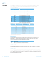
There are a number of Development Kits to choose from depending on the OEM needs, the complete
list is in the table below.
LT2510 Development Kits*
2 www.lairdtech.com
Part Number
Description
DVK-PRM110
(2) LT2510 200mW transceivers w/U.FL connector
(1) RS232 serial adapter board
(1) USB serial adapter board
(1) DB9 (F) to DB9 (F) RS232 cable
(1) USB cable 6 ft.
(2) 2.4GHz 1/2 dipole antennas
Laird Technologies Tools & Literature Disk
DVK-PRM111
(2) LT2510 200mW transceivers w/integrated antenna
(1) RS232 serial adapter board
(1) USB serial adapter board
(1) DB9 (F) to DB9 (F) RS232 cable
(1) USB cable 6 ft.
Laird Technologies Tools & Literature Disk
DVK-PRM112
(2) LT2510 200mW transceivers w/U.FL connector
(1) RS232 serial adapter board
(1) USB serial adapter board
(1) DB9 (F) to DB9 (F) RS232 cable
(1) USB cable 6 ft.
(2) 2.4GHz 1/2 dipole antennas
Laird Technologies Tools & Literature Disk
DVK-PRM113
(2) LT2510 100mW transceivers w/integrated antenna
(1) RS232 serial adapter board
(1) USB serial adapter board
(1) DB9 (F) to DB9 (F) RS232 cable
(1) USB cable 6 ft.
Laird Technologies Tools & Literature Disk
Laird Technologies
LT2510
DVK
HARDWARE
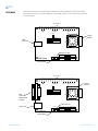
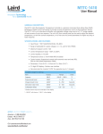
The LT2510 DVK board is provided so that the developer can use a standard PC interface to operate
the transceivers and to aid in system integration. It uses either a RS232 or USB data format to interface
to the transceiver.
TEST TERMINALS
A
B
C
D
E
F
LINK TXD
LEDs
RXD
G
H
I
J
K
LEDs
M
N
LEDs
18
RESET
USB
Connector
L
10
LT2510
Module
19
J9-1
J9-2
Loopback Mode
J9-3
J9-4
Normal Operation
J9-5
J9-6
Force 9600 Baud
22
1
9
Power On LED
POWER
ON
OFF
Dig Pwr In
SDK Board
PA Pwr In
J4-1
J4-2
J4-3
J4-4
J4-5
J4-6
J
K
Dig Pwr Out
PA Pwr Out
Power Switch
TEST TERMINALS
A
B
C
D
E
F
LINK TXD
LEDs
RXD
G
H
I
LEDs
M
N
LT2510
Module
LEDs
18
RESET
DB9
Connector
RS232 Serial
Interface
L
J9-1
J9-2
Loopback Mode
J9-3
J9-4
Normal Operation
J9-5
J9-6
Force 9600 Baud
10
19
22
1
9
Power On LED
Power Jack
Dig Pwr In
OFF
SDK Board
ON
POWER
PA Pwr In
J4-1
J4-2
J4-3
J4-4
J4-5
J4-6
Dig Pwr Out
PA Pwr Out
Power Switch
3 www.lairdtech.com
Laird Technologies
LT2510
DVK
HARDWARE
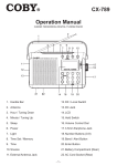
The configuration and operation of the LT2510 DVK board is continuously shown by the LEDs located
on the front edge of the board. Refer to the following tables for definitions of the LEDs and DB9
connector pin assignments.
LED
LED Color
Purpose
B
Green
This LED will illuminate when GIO_6 is low.
C
Red
This LED will illuminate when GIO_4 is low.
I
Green
This LED will illuminate when 9600_BAUD is high.
J
Red
This LED will illuminate when GIO_7 is low.
K
Red
This LED will illuminate when GIO_3 is low.
L
Green
This LED will illuminate when GIO_2 is low.
M
Red
This LED will illuminate when GIO_1 is low.
N
Green
This LED will illuminate when GIO_0 is low.
LINK
Red
This LED will illuminate when In_Range is high.
TXD
Green
This LED will illuminate when TXD is low.
RXD
Red
This LED will illuminate when RXD is low.
Power
Green
This LED will illuminate when the POWER switch is
turned on and the module is receiving power.
DB9 Pin
Signal Name
Description
Direction1
1
DCD
Data Carrier Detect
I
2
RXD
Received Data
I
3
TXD
Transmitted Data
O
4
DTR
Data Terminal Ready
O
5
GND
Signal Ground
6
DSR
Data Set Ready
I
7
RTS
Request to Send
O
8
CTS
Clear to Send
I
9
RI
Ring Indicator
I
1. Note: I/O direction is relative to the PC.
POWER SWITCH
The LT2510 DVK board is equipped with a power switch. This switch is used to turn the power to the
board on and off. This power switch should be turned OFF when the USB or power supply cable is
connected or disconnected to prevent possible damage to the board.
Switch
Description
Power
When set to the OFF position, power will be removed from
the DVK board and the LT2510 transceiver.
JUMPER USAGE
The LT2510 DVK board utilizes a set of jumpers to accomplish certain tasks. There are two sets of jumpers,
the J4 set and the J9 set.
JUMPER SET J4
The J4 set of jumpers is used to complete the circuits that supply power to the radio. There are two jumpers,
and BOTH JUMPERS MUST BE PROPERLY INSTALLED for the module to operate. A jumper MUST be installed
on J4-1 and J4-2 to supply power to the radio itself. Another jumper MUST also be installed on J4-5 and J4-6
to supply power to the power amplifier.
4 www.lairdtech.com
Laird Technologies
LT2510
DVK
HARDWARE
JUMPER SET J9
The J9 set of jumpers is used to control how the development kit board will operate. Only one jumper is used
with this jumper set. There are three operational modes:
• Loopback – When the jumper is installed on pins J9-1 and J9-2 the unit will operate in loopback mode. This means that the radio will receive data and then turn around and transmit the same data. The loop
is on the serial interface of the module and points back to the radio. This jumper is useful for range testing.
• Normal Operation – When the jumper is installed on pins J9-3 and J9-4, the unit will operate in its
normal mode. This means that the radio will operate however it is configured using the DVK
software application.
•
Force 9600 Baud – When the jumper is in stalled on pins J9-5 and J9-6, the unit will only operate at
9600 Baud. This is a recovery mode that is used when the user is unable to communicate with the
radio. This mode places the unit in a known operating state so the user can go in and access the
programmed data via the development software.
Jumper ID
Label
Usage
J4-1
Dig Pwr In
J4-2
Dig Pwr Out
A jumper MUST be connected to these two pins for operation.
This is the power supply circuit for the radio.
J4-3
Not Used
Not Used
J4-4
Not Used
Not Used
J4-5
PA Pwr In
J4-6
PA Pwr Out
A jumper MUST be connected to these two pins for operation.
This is the power supply circuit for the power amplifier.
J9-1
Loopback
J9-2
Loopback
J9-3
Normal Operation
J9-4
Normal Operation
J9-5
Force 9600 Baud
J9-6
Force 9600 Baud
To configure the radio for loopback operation, a jumper will be connected
to these two pins. A jumper MAY NOT be connected to the Normal Operation
or Force 9600 Baud pins at the same time.
During normal operation, a jumper will be connected to these two pins.
A jumper MAY NOT be connected to the Loopback or Force 9600 Baud pins
at the same time.
To force the radio to operate at 9600 Baud, a jumper is connected
to these two pins. A jumper MAY NOT be connected to the Loopback
or Normal Operation pins at the same time.
Interfacing the LT2510 DVK To Other RS232 Hardware
The development kit serial board is defined as a DCE (Data Communications Equipment) device. A DCE device is
wired to the interface directly with the DTE (Data Terminal Equipment) device. Typically, a DTE device is defined
as a PC, while a DCE device is defined as a peripheral. To interface a DCE device to other DCE device, or a DTE
device to another DTE device, a null modem is required. The null modem simply swaps pins to convert a DCE
device to a DTE device, and vice-versa. Normally, a null modem consists of a female and a male DB9 connector.
A typical null modem configuration is shown in the following graphic.
5 www.lairdtech.com
DB9 Pin Signal
Name
DCE
DTE Pin
Direction
Signal
Name
DTE
Direction
Null Modem
Female DB9
Null Modem
Male DB9
1
DCD
O
1
DCD
I
1
4 or NC
2
RXD
O
2
TXD
I
2
3
3
TXD
I
3
RXD
O
3
2
4
DTR
I
4
DTR
O
4
6 & 1 or NC
5
GND
5
GND
5
5
6
DSR
O
6
DSR
I
6
4 or NC
7
RTS
I
7
RTS
O
7
8
8
CTS
O
8
CTS
I
8
7
9
RI
O
9
RI
I
9
NC
Laird Technologies
LT2510
DVK
SOFTWARE
DVK Software Installation
Locate the OEM software folder on the Laird Technologies Tools & Literature CD and install the development
kit software. To install the software, run Setup.exe and follow the installation prompts. During the installation,
the software will prompt the user to install the Laird Technologies USB Driver. It is recommended that the user
installs the driver at the same time as the software. The first time the software is run, the following message
will be displayed:
Click “OK.” The software will attempt to open COM1 of the PC. If there is a conflict or the port does not exist, the
software will show the port as unavailable. This error will be displayed when one of the following conditions exists:
• There is other software running that has control over the COM1 port. Locate this software and shut it
down while running “Laird OEM.exe” software.
• The PC either does not have a COM1 port or the port has been disabled.
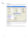
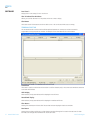
PC Settings Tab
The PC Settings tab is shown in the following graphics, as it will appear the first time the program is run.
Select the LT2510 in the Product pull-down menu. Doing this will automatically select the default baud rate of
115200. Use the Find Ports button to search Windows for existing Com Ports. The ports will then be available
in the drop-down for the Port1 Settings. If the desired Com Port is not found, you can manually add it with
the Add Ports button. If the COM port is listed as unavailable, a different COM port can be selected in the Port
pull-down menu. The application can use two serial ports if the Enabled: box is checked under Port 2 settings.
6 www.lairdtech.com
Laird Technologies
LT2510
DVK
SOFTWARE
Port 1/Port 2 Options
The application can control up to (2) COM ports, including virtual COM ports, which physically map to USB
or Ethernet ports. The Port pull-down menu allows selection of COM1 through COM16. An error message
will be displayed if a port is selected that is either nonexistent or already occupied by another program.
When a port selection is made, the application will attempt to open the port and list its status as:
• Unavailable
• Open
• Closed
The Port Status is shown just above the Port pull-down menu and also in the status bar at the bottom of the
screen. The software will only be able to communicate with a radio if the Port Status is Open.
Although menus are shown for Baud Rate, Parity, Handshaking, Data Bits, and Stop Bits, only the Baud Rate,
Parity and Handshaking menu selections can be changed.
Options
The application also provides the following options:
Save Settings On Exit
When this option is enabled, all changes made to the Settings tab will be automatically loaded the next time
the application is run. Otherwise, any changes made will be discarded.
Read/Write With AT Commands
When this option is enabled, the application will use AT Commands for its read/write EEPROM functions
instead of the standard configuration commands. This box should be checked at all times unless Pin 15
(CMD/DATA) is pulled Logic Low.
Auto Baud
When this option is enabled, the application will scan all available COM Ports using the most common
baud rates, until a radio is found. If no radio is found or the application cannot open the port, an error
message will be reported. The application will only use Auto Baud when prompted by the user after an
unsuccessful read process.
Auto Archive
When this option is enabled, the application will archive the EEPROM settings for each radio after a successful
write process.
Although not required, the application will prompt the user to type a description of the changes made.
Auto Archive can be used to restore the radio to a previously known working configuration.
Monitor UDP For New Devices
This option is used for legacy ConnexNet products and does not apply to the LT2510.
Status Bar
Located at the bottom of the application window, the status bar gives the state of Port 1, RTS Port 1, CTS
Port 1, Port 2, RTS Port 2, and CTS Port 2 lines. When the text appears black, the current state will be shown.
When the text appears gray, the current state will not be shown. The text shown in the bottom status bar
gives a simplified status of the current, pending software process. The software has no pending process when
“Communications Idle” is shown. On the right side of the status bar a progress bar is maintained to indicate
the progress of longer commands such as a Find Ports or Write Radio.
About Button
The About button can be pressed to determine the revision number of the application and the contact
information for Laird Technologies.
7 www.lairdtech.com
Laird Technologies
LT2510
DVK
SOFTWARE
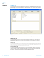
Configure Tab
The configure tab is used to display the 256 byte EEPROM contents. The screen is able to do this in two formats:
• GUI
• Hexadecimal
The GUI format is the default method of display. The user may change the display by using buttons located in the
lower left corner of the application window. Clicking on the GUI View button will display the data in GUI format,
while clicking on the EEPROM Editor View button will display the data in hexadecimal.
8 www.lairdtech.com
Laird Technologies
LT2510
DVK
SOFTWARE
Read Radio Button
To update the Configure and EEPROM Editor View pages with the EEPROM contents of a radio currently connected
to the proper port on the PC, click the Read Radio button. A successfully read radio will result in the following
message being displayed:
Write Radio Button
After making changes to the controls on the Configure tab, the Write Radio button can be pressed to save those
changes to the radio EEPROM.
Port 1/Port 2 Buttons
When the Port 1 button is depressed, the Write Radio and Read Radio buttons communicate through Port 1.
When the Port 2 button is depressed, the Write Radio and Read Radio buttons communicate through Port 2.
9 www.lairdtech.com
Laird Technologies
LT2510
DVK
Software
Calc Baud Button
The Baud pull-down menu includes all standard PC baud rates. In some rare cases, a user may want to use a
non-standard baud rate. To do this, the user will need to click on the Calc Baud button. The Calculate Baud
Rate dialog box will appear.
To calculate the settings for a particular baud rate, type that baud rate into the Desired Baud Rate text field.
If the number in the Desired Baud Rate text field is ±3% of an acceptable baud rate, the rest of the fields
in the Calculate Baud Rate will automatically populate. If the baud rate is not supported by the radio, the
remaining text fields will continue to display the number 0.
An example of an acceptable non-standard baud rate being accepted is shown in the following graphic:
Acceptable Baud Rate Found
Acceptable Baud Rate Found
No Acceptable B
No Acceptable Baud Rate Found
Clicking the Save button will cause the baud rate shown in the Actual Baud Rate window to be displayed in the
Baud window on the Configure tab of the application. Clicking Cancel will ignore these changes. The Actual Baud
Rate will not always match the Desired Baud Rate. However, the program verifies that the Desired Baud Rate is
within 3% of the Actual Baud Rate (as required by the radio).
10 www.lairdtech.com
Laird Technologies
LT2510
DVK
Software
Hex/Decimal Button
All of the text entry type boxes found on the Configure tab have an indication of whether the value is presented
in Hexadecimal (Hex) or Decimal (Dec). The indication (Hex or Dec) can be pressed to toggle between Hexadecimal
and Decimal notation.
GUI View Button
Clicking the GUI View Button enables a GUI representation of the 256 byte EEPROM contents of the radio.
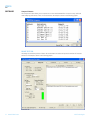
EEPROM Editor View Button
Clicking the EEPROM Editor View enables a hexadecimal dump of the full 256 byte EEPROM resident on the radio.
The EEPROM Editor View is shown in the following graphic, as it will appear after a radio has been successfully
read:
Load File Button
This button is used to load a file previously created by this application can be loaded to restore an EEPROM to a
former state.
Save to File Button
This button is used to save an EEPROM program to a file. This allows for the current state of the EEPROM to be
restored at a later time.
11 www.lairdtech.com
Laird Technologies
LT2510
DVK
Software
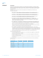
Compare EE Button
The Compare EE button allows you to compare two or more saved EEPROM files. This can be a very useful tool
when analyzing performance of two or more transceivers. An example is shown in the following graphic:
Range Test Tab
The Range Test tab allows packets of data to be sent between two radios and reports the numbers of successes
and errors. An example is shown in the following graphic:
12 www.lairdtech.com
Laird Technologies
LT2510
DVK
Software
Test Selection
There are six test options that can be selected. For each of these options, excluding Port 1 Send Only, the DVK
application will perform data verification as part of the test. This means that the application will send specific data
out and the application expects a specific response to that transmission. If it does not get that specific response,
it will report an error.
Important: The ports referred to are Ports for the application, NOT the Windows communication ports.
The available selections are:
• Port 1 -> Port 2 – This test selection is used when two development kits are connected to one PC.
This selection is used to send data from the radio connected to Port 1 to the radio connected to Port 2.
• Port 2 -> Port 1 – This test selection is used when two development kits are connected to one PC.
This selection is used to send data from the radio connected to Port 2 to the radio connected to Port 1.
• Port 1 <-> Port 2 – This test selection is used when two development kits are connected to one PC.
This selection is used to send bidirectional data from both radios connected to the PC.
• Port 1 Send Only – This test selection is used when one development kit is connected to a PC.
This selection is used only to send data from the radio connected to Port 1. This would most often be
used when the remote radio is connected to a second PC and is running the Port 1 Receive Only test.
There is no data verification with this option.
• Port 1 Receive Only – This test selection is used when two PCs are being used with two development kits.
One development kit is connected to each PC. When this selection is made, the radio attached to the
port of PC 1 will be receiving data sent from the radio attached to PC 2, which is set to Port 1 Send Only. Both PCs should be set up with the same number of bytes in the Create Data field.
Important: The test on both computers should be initiated at the same time. If this is not done, there may
be some errors reported until the two radios synchronize with each other.
• Port 1 Loopback – This test selection is used with two development kits and one PC. The PC will be
connected to one development kit and will be running the development software. The second development
kit will be powered on. The radio attached to the second development kit is set up in loopback mode, using
a jumper to connect jumper pins J9-1 and J9-2. The radio attached to PC 1 will transmit data to the remote
radio. The remote radio will receive the data and retransmit it back to the radio attached to PC 1.
There are three typical hardware setups.
1.One radio is plugged into a serial or USB port on a PC. The second radio is plugged into a separate power
supply with a loopback adapter connected.
2.One radio is plugged into a serial or USB port on a PC. The other radio is plugged into a different serial
or USB port on the same computer.
3.One radio is plugged into a serial or USB port on a PC. The other radio is connected to a serial or USB port
on another PC.
If using two PCs for the test, the application run on both sides should have the second COM port disabled on
the PC Settings tab.
13 www.lairdtech.com
Test Selection
Port 1 Action Port 2 Action
Hardware Setup
Port 1 -> Port 2
TX
RX
2
Port 2 -> Port 1
RX
TX
2
Port 1 <-> Port 2
TX/RX
TX/RX
2
Port 1 Send Only
TX
N/A
3
Port 1 Receive Only
RX
N/A
3
Port 1 Loopback
TX/RX
N/A
1
Laird Technologies
LT2510
DVK
Software
Transmit Packet Selection
This section allows you to select the data packet used to perform the Range Test. You may either create data
of a specified byte length or load your own text or configuration file.
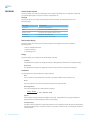
Test Type
The test type allows you to select how long the test will be performed. The choices are shown in the
following graphic:
Test Type
Description
Continuous
Test will run until stopped.
Timed
Test will run for a specified time period.
Number of Runs
Test will run for a specified number of runs.
Single Step
Test will run for a single step.
Break on Error
Test will run until an error occurs.
Receive Packet Display
This section allows you to select how the received packets will be displayed. The user is provided the
following options:
• ASCII or Hexadecimal format
• Packet Time Stamp
• Only Display Errors
Timing
This section allows you to modify the TX and RX timing of the test.
TX Delay
This field allows the operator to change the amount of delay between transmissions (in milliseconds {ms}).
RX Timeout
This field allows the operator to change the amount of time to allow for a packet to be displayed.
Test Results
The Test Results area is used to display the results of the test.
Runs
The run number is incremented every time a test is completed, whether errors occurred or not.
Errors
This is the number of errors that occurred while the test was being performed.
Percentage Good
This is the percentage of test results that were successful.
Runs - Errors
X 100 = Percent Good
Runs
14 www.lairdtech.com
Approx.
This is a display of the approximate throughput of the radio. The application uses a rough calculation to
display the amount of data transferred in bits per second (bps).
Time Remaining
This field is used to indicate how much longer the test will run. Depending on how the test was initially setup, this field may display time, or if the test was set to run a specific number of runs, it will display the number of runs that remain.
Laird Technologies
LT2510
DVK
Software
Port 1/Port 2
Displays the Tx or Rx activity for Port 1 and Port 2.
View Tx Packets/View Rx Packets
Allows you to switch between Tx or Rx packets in the Port 1/Port 2 display.
Clear Button
This button sets all of the statistics and errors back to zero. This can be used while a test is running.
Terminal/Chat Tab
The Terminal/Chat tab is used to send small data packets between two COM ports. As data is received it
is appended to the appropriate Port window. An example of the Terminal/Chat tab is shown below.
Send Button
This button is used to send the data in the textbox out of the selected port(s). The current user’s Windows username
is also sent with the data.
ASCII Display
When selected, newly received data will be displayed in ASCII format.
Hexadecimal Display
When selected, newly received data will be displayed in Hexadecimal format.
Clear Button
Pressing the Clear Button will erase all of the text that has been displayed in both text windows.
Font Button
Pressing the Font button will bring up a font selection window allowing the font used in the text boxes for both
terminals to be changed. Both terminals will use the same font.
15 www.lairdtech.com
Laird Technologies
LT2510
DVK
Software
Command Tab
The Command tab is used to send configuration, CC (product family dependent) and AT commands (product
family dependent) to the radio on the selected port. Below is an example of the Command tab for the LT2510
product family:
Radio Buttons
The application sends one command at a time. The command can be selected by clicking the radio button next
to that command.
Command Name Field
The Command Name field consists of a list of the most commonly used commands for the module. Additional
commands may be added to the list. The length of the Command Name is not restricted and is not required by
the application.
Command Field
The Command field contains a list of the commands for each of the command names in the Command Name field.
When a command name is selected in the Command Name field, the command that is in the same position in the
adjacent Command field is the command that will be sent to the radio.
Optional Comments Field
The Optional Comments field is where the user may enter any comments that they would like to accompany the
command information. This field is not restricted in length and is not required by the application. The description
for a particular command will be displayed when that commands radio button is selected.
16 www.lairdtech.com
Laird Technologies
LT2510
DVK
Software
Received Data Port 1/Port 2 Window
Data received over the serial port while on the Command tab (whether in response to a command or not) will be
displayed in the Received Data window in hexadecimal format.
AT Enter/Exit Command Mode
When selected, the radio will enter/exit AT Command mode as required to complete the selected command
by creating a virtual version of the Command/Data Line.
Perform Reset After Completion
When enabled, the radio will be reset after the selected command has completed. This is useful when writing
EEPROM changes, which only take affect after a reset.
Port 1/Port 2 Buttons
When Port 1 is depressed, received data will be shown for Port 1. When Port 2 is depressed, received data will
be shown for Port 2.
Send Comm
This button sends the selected command out of the selected serial port.
17 www.lairdtech.com
Laird Technologies
LT2510
DVK
Troubleshooting
Problem
Solution
No lights on DVK Board.
1. Check the power connection. The VCC LED should be lit when power
is applied to the serial board.
2. Make sure there is nothing shorting VCC to GND and that the radio
is seated into it’s interconnect board properly.
3. Make sure that the Power switch is in the On Position.
Radio EEPROM cannot be read by Laird
Technologies OEM.exe.
1. Verify that power is applied and that the serial/USB cable is connected
to the serial board and the PC.
2. Verify that the correct serial/USB port is selected in the software
(Port 1 or Port 2).
3. Verify baud rate and port address on the PC Settings page.
4. Verify the Port Status is Open in the Status bar or in the Port 1
Settings on the PC Settings tab.
EEPROM can be read/viewed with the OEM
software, but data cannot be sent between
the two transceivers using OEM.exe.
1. Reset both radios.
2. Make sure both transceivers have the same Channel Number
and System ID
3. Check all cables and connections.
4. Make sure one radio is a Server and one is a Client.
5. Check radio addressing.
6. Make sure that radios are separated by at least ten feet.
7. Make sure the In Range LED is lit on both transceivers.
Packets can be sent between both radios
using OEM.exe but cannot be sent from
software or hardware not supplied by
Laird Technologies
1. Use the Hardware section of this manual to determine if a
null-modem adapter is required for interfacing to the hardware.
2. Make sure the baud rate of the radios matches that of the
OEM Host hardware.
A Framing or Data Timeout error occurs
while running a Range Test.
1. Verify that the baud rate on the PC Settings page matches that
of the radio’s EEPROM.
2. Verify that both radios are powered on and that the Port settings
are correct.
3. Verify that the In Range LED is lit on both radios.
Technical Support
Please refer to the contact information included in the DVK for further details. For all other inquiries, please refer
to the LT2510 Quick Start Guide and LT2510 User’s Manuals.
LT2510 Basics and Tips
1.There needs to be one and only one Server per network (RF Channel Number & System ID); there can
be any number of Clients.
2.The Default configuration is a Client radio with the addressing mode not set. For the radios to
communicate the addressing must be set to either:
• Broadcast Mode
• Auto Destination (for Clients only)
• The MAC Address of the remote radio must be entered into the Destination Field.
3.The Link LED on the Server will always be lit. The Link LED on a Client will only be lit when it is in sync
with a Server. The Link light must be lit for RF communications to occur.
4.Configuration should always be performed with the Laird Technologies Windows OEM Configuration
Utility. Though the radios are serial modems accessible through traditional terminal emulators, such
as HyperTerminal, the AT commands must be sent in their entirety, which cannot be achieved when
typed in. Once configured testing can be performed with HyperTerminal or another emulator to send
serial data.
5.Windows only allows one program to access a Serial Communications Port at a time. Therefore when
the Laird Technologies Windows OEM Configuration Utility is open, no other serial applications should be open.
6.When using the USB Evaluation Board, it is recommended to Close the Port on the PC Settings tab prior
to unplugging the USB cable or powering off the module. If not, the port may become unavailable and
need to be either toggled by Closing and Opening the Port or the software may need to be reset.
7.The PC Settings tab is used to set the configuration of the OEM Configuration Utility, not the radio.
The Configuration Tab is used to configure the radio, but the radio’s EEPROM must be read first.
18 www.lairdtech.com
Laird Technologies
Laird Technologies is the world leader in the design and
manufacture of customized, performance-critical products for wireless and other
advanced electronics applications.
Laird Technologies partners with its customers to find
solutions for applications in various industries such as:
Network Equipment
Telecommunications
Data Communications
Automotive Electronics
Computers
Aerospace
Military
Medical Equipment
Consumer Electronics
Laird Technologies offers its customers unique
product solutions, dedication to research and
development, as well as a seamless network of
manufacturing and customer support
facilities across the globe.
WS-UM-LT2510-DVK 0309
Copyright © 2009 Laid Technologies, Inc. All rights reserved.
The information contained in this manual and the accompanying software programs are copyrighted and all rights are reserved by Laird Technologies, Inc. Laird Technologies, Inc. reserves the right to make periodic
modifications of this product without obligation to notify any person or entity of such revision. Copying, duplicating, selling, or otherwise distributing any part of this product or accompanying documentation/software
without the prior consent of an authorized representative of Laird Technologies,Inc. is strictly prohibited.
All brands and product names in this publication are registered trademarks or trademarks of their respective holders.
This material is preliminary
Information furnished by Laird Technologies in this specification is believed to be accurate. Devices sold by Laird Technologies are covered by the warranty and patent indemnification provisions appearing in its Terms
of Sale only. Laird Technologies makes no warranty, express, statutory, and implied or by description, regarding the information set forth herein. Laird Technologies reserves the right to change specifications at any
time and without notice. Laird Technologies’ products are intended for use in normal commercial and industrial applications. Applications requiring unusual environmental requirements such as military, medical lifesupport or life-sustaining equipment are specifically not recommended without additional testing for such application.
Limited Warranty, Disclaimer, Limitation of Liability
For a period of one (1) year from the date of purchase by the OEM customer, Laird Technologies warrants the OEM transceiver against defects in materials and workmanship. Laird Technologies will not honor this
warranty (and this warranty will be automatically void) if there has been any (1) tampering, signs of tampering; 2) repair or attempt to repair by anyone other than an Laird Technologies authorized technician. This
warranty does not cover and Laird Technologies will not be liable for, any damage or failure caused by misuse, abuse, acts of God, accidents, electrical irregularity, or other causes beyond Laird Technologies’ control,
or claim by other than the original purchaser. In no event shall Laird Technologies be responsible or liable for any damages arising: From the use of product; From the loss of use, revenue or profit of the product; or
As a result of any event, circumstance, action, or abuse beyond the control of Laird Technologies, whether such damages be direct, indirect, consequential, special or otherwise and whether such damages are incurred
by the person to whom this warranty extends or third party. If, after inspection, Laird Technologies’ determines that there is a defect, Laird Technologies will repair or replace the OEM transceiver at their discretion. If
the product is replaced, it may be a new or refurbished product.