1
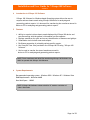
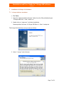
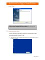
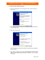
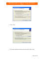
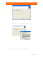
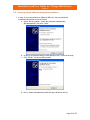
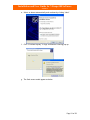
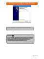
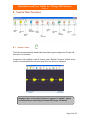
Installation and User Guide for
ViScope 100
Real Time Data Transfer Software to PC
Version 3.1
HD Medical Services India Pvt Limited
#48, Industrial Estate, Perungudi,
Chennai-600096 INDIA.
Installation and User Guide for ViScope100 Software
Version 3.1
Installation and User Guide for
ViScope 100
Real Time Data Transfer Software
to PC
Version 3.1
0602-50002-006
Page 2 of 39
Installation and User Guide for ViScope100 Software
Version 3.1
Table of Contents
1 Intended Use ............................................................ 5
2 Conventions used in this User Guide ................................. 5
3 User Assistance.......................................................... 5
4 Introduction to ViScope 100 Software ............................... 6
5 Features .................................................................. 6
6 System Requirements .................................................. 6
7 Installation of ViScope 100 Software: ............................... 7
7.1
7.2
7.3
7.4
7.5
ViScope 100 Driver installation.......................................................................... 7
Installing the USB cable Drivers ........................................................................ 8
Installation of Serial Port: ................................................................................. 14
ViScope 100 Software installation.................................................................... 18
Connecting ViScope 100 Device through Different USB Ports....................... 20
8.1
“Refresh” Button
8.2
8.3
“Open” Button
..................................................................................... 25
“Freeze” Button from Device (not in the software).......................................... 26
Launching ViScope 100 Software .........................................22
Launching ViScope 100 Software .........................................23
8 Tools & Their Functions...............................................24
.......................................................................... 24
8.4
“Save” Button
.................................................................................. 27
8.4.1
Transferring of waveforms to PC ........................................................ 28
8.5
8.6
“Caliper” Button
................................................................................... 30
Thumb Views.................................................................................................... 31
8.7
“Zoom” Button
8.8
Zoom out
8.9
Player
8.10
Print Button
8.11
Report
................................................................................................... 35
8.12
Search
........................................................................................................ 35
................................................................................... 31
............................................................................................... 33
..................................................................................................... 33
....................................................................................... 34
9 Uninstalling ViScope 100 Software ..................................37
10 Common Error Messages and Rectification.........................38
Page 3 of 39
Installation and User Guide for ViScope100 Software
Version 3.1
Page 4 of 39
Installation and User Guide for ViScope100 Software
Version 3.1
1
Intended Use
This user guide is a reference for Real time data transfer from ViScope 100 to PC
hereinafter referred to as “ViScope 100 Software”. It provides information on the
features and functions.
Before going through ViScope 100 Software, user should become
thoroughly familiar with ViScope 100 device operation.
Read the information in this user guide before using “ViScope 100
Software”
2
Conventions used in this User Guide
¾ When steps in operating ViScope 100 Software are numbered, it implies that it
should be followed in sequence.
¾ Bulleted lists represent information, but do not imply a sequence.
¾ V x.x.x represents respective versions of software provided in general.
3
User Assistance
For Technical information and assistance Contact
[email protected]
Page 5 of 39
Installation and User Guide for ViScope100 Software
Version 3.1
4
Introduction to ViScope 100 Software
ViScope 100 Software for Windows based Operating system allows the user to
acquire and save heart sounds using ViScope 100 device for analyzing and
generating patient reports. It is also used for transferring the waveforms stored in
device to PC for analyzing and generating patient reports.
5
Features
¾ Ability to acquire/retrieve heart sounds displayed by ViScope 100 device and
save them along with the patient’s information on the computer.
¾ Displays waveforms for quick and correct identification of murmurs and gallops.
¾ Visualization tools include zoom and calipers.
¾ Facilitates generation of printable patient specific reports.
¾ Can View the Tutor files provided in the ViScope 100 CD using “ViScope 100
Software”.
¾ Can be used to transfer the stored waveforms stored in
device to PC for analyzing and generating patient reports.
NOTE: Tutor waveforms and other files saved using ViScope 100 Software can
ONLY be opened with ViScope 100 Software.
6
System Requirements
Recommended operating system - Windows 2000 / Windows XP / Windows Vista
RAM Requirements – Minimum 64MB
Hard disk Space – 100MB
NOTE: ViScope 100 Software is best suited for PC monitor resolution of
1024 X 768 Pixels
Page 6 of 39
Installation and User Guide for ViScope100 Software
Version 3.1
7
Installation of ViScope 100 Software:
7.1 ViScope 100 Driver installation
•
For Vista :
1. Open the “Data acquisition Software” folder from the CD provided and open
“ViScope USB Driver - Vista” folder in it.
2. Double click on “setup.exe” to initiate installation
Data acquisition Software Æ ViScope USB Driver Æ Vista Æ setup.exe
This brings the initial driver set-up screen as follows
3. Select “I accept” and click next.
Page 7 of 39
Installation and User Guide for ViScope100 Software
Version 3.1
4. Select “Finish”
NOTE: For Win XP and Win 2000 Professional the user can start with
Setup procedure as mentioned in Sec 7.2 below
7.2 Installing the USB cable Drivers
Connect the ViScope 100 Device and your PC with the USB – Cable
provided along with ViScope 100 Kit.
1. “New hardware found” message would pop up at the bottom right corner of
the Monitor as below.
Page 8 of 39
Installation and User Guide for ViScope100 Software
Version 3.1
•
For Win XP & Win 2000 Professional :
2. Select the second option “Yes, now and every time I connect a device” &
select “Next”
3. Select the second option “Install from list or specific location (Advanced)”
in the resulting screen.
4. Click “Next” and proceed.
This will lead the user to specify the folder in which the driver installation
files are located.
5. Click “Browse” and select the location “Data acquisition Software\ViScope
USB Driver\Win 2000 Professional & WinXP \ SYS Files” from the original
CD contents
Page 9 of 39
Installation and User Guide for ViScope100 Software
Version 3.1
6. Select “Next”
7. The system completes the search and locates the file, Select “Next”
Page 10 of 39
Installation and User Guide for ViScope100 Software
Version 3.1
8. In case the following screen appears click “Continue Anyway”
9. Once the installation is completed, select “Finish”
Page 11 of 39
Installation and User Guide for ViScope100 Software
Version 3.1
•
For Vista :
1. Select “locate and install driver software(recommended)”
2. Select “Browse my computer for driver software(advanced)”
Page 12 of 39
Installation and User Guide for ViScope100 Software
Version 3.1
3. Browse to path “Data acquisition Software\ViScope USB Driver\ Vista\
windows\ tiinst\ TUSB3410\ Vista32”
4. Select Next
Page 13 of 39
Installation and User Guide for ViScope100 Software
Version 3.1
5. Click Continue anyway
6. Click Finish.
7.3 Installation of Serial Port:
• For Win XP & Win 2000 Professional :
1. Once the USB drivers are installed, Select second option “Install from list
or specific location (Advanced)” from the next instruction screen that
pops up. Select “Next”
Page 14 of 39
Installation and User Guide for ViScope100 Software
Version 3.1
2. Browse the same path as earlier “Data acquisition Software\ViScope USB
Driver\Win 2000 Professional & WinXP \ SYS Files” & select “next”
3. This will complete the port - driver installation and the following screen
will appear. Select “Continue Anyway”
Page 15 of 39
Installation and User Guide for ViScope100 Software
Version 3.1
4. click “Finish”
Plug out the device from the PC USB port and start the ViScope 100
Software Setup procedure for installation as mentioned in Sec 7.4 below
•
For Vista:
1. click next
Page 16 of 39
Installation and User Guide for ViScope100 Software
Version 3.1
2. Select “Install this Driver software anyway”
3. click finish
Plug out the device from the PC USB port and start the ViScope 100
Software Setup procedure for installation as mentioned in Sec 7.4 below
Page 17 of 39
Installation and User Guide for ViScope100 Software
Version 3.1
7.4
ViScope 100 Software installation
1. Select the ‘ViScope 100 V 3.1 exe’ from the contents of the CD.
Data acquisition SoftwareÆ Setup Files Æ ViScope 100 V3.1 exe
Select “Next”
2. It is recommended to install the software in the default location specified
in the below screen and click ”Next”
3. This will automatically ask for confirmation to install; select “Install”
Page 18 of 39
Installation and User Guide for ViScope100 Software
Version 3.1
4. Once installation is complete, the following screen will be displayed
5. Select “Finish”
In case you need to start using ‘ViScope 100 Software’ immediately;
you should click select the “Launch ViScope” option and make sure
the device is first Powered ON and is then connected to the PC
through the USB cable provided. The “New hardware detected &
ready to use” pop up message window will appear.
A Desktop Icon will automatically display after completing the above
installation
Page 19 of 39
Installation and User Guide for ViScope100 Software
Version 3.1
7.5 Connecting ViScope 100 Device through Different USB Ports
1. In case it is re-connected to a different USB port, the port detection
installation should be re-run as follows:
a. Select the first option “Install the software automatically
(Recommended)” and click ”Next”
b. In case a verification testing screen appears click “Continue Anyway”
c. Click “Finish” on the resulting screen
d. Now it would automatically install the port detection set up.
Page 20 of 39
Installation and User Guide for ViScope100 Software
Version 3.1
e. Select to detect automatically and continue by clicking “Next”
f. Click “Continue Anyway” in logo verification & testing pop up.
g. The final screen would appear as below
Page 21 of 39
Installation and User Guide for ViScope100 Software
Version 3.1
An audio confirmation can be heard after successful installation.
Disclaimer
Anti-virus software can interfere with data collection from hardware
devices. If by following the procedures mentioned above still if no
signal displayed in the screen, please deactivate Anti-virus if
installed/running and repeat the installation process.
Page 22 of 39
Installation and User Guide for ViScope100 Software
Version 3.1
Launching ViScope 100 Software
Check weather the Device and PC are connected through USB port,
(Mini USB end of connector cable to ViScope 100 device, and other
end to PC)
The device should be Powered ON
•
Launch ViScope 100 Software by double clicking the short cut icon on the
desktop.
•
Alternatively select “ViScope 100” under the complete list of “Programs” from
“Start menu”. The opening screen displaying the controls and the sound signal
from ViScope 100 device is displayed below.
Opening Screen of ViScope 100 Software
(To know more about Operations of “ViScope 100” device, refer to the ViScope
100 User Manual)
Page 23 of 39
Installation and User Guide for ViScope100 Software
Version 3.1
8 Tools & Their Functions
8.1 “Refresh” Button
The Software automatically obtains Real time data signals coming from ViScope 100
device as it is activated.
Irrespective of the display on the PC screen, when “Refresh” button is clicked, entire
screen is refreshed and the real time signal from the device is displayed.
Message screen “Device Not Connected” appears if “Refresh” button
is clicked without connecting a Powered ON ViScope 100 device.
Page 24 of 39
Installation and User Guide for ViScope100 Software
Version 3.1
New
8.2 “Open” Button
The “Open” button is used to open a saved heart sound signal.
1. By clicking open button two tabs displaying “Demo files” and “Existing
files” will be displayed. The user can select any one of these tabs and
select the listed files under each tab.
2. Demo files are the “Tutorial waveforms” for understanding
normal/abnormal heart sounds where as, Existing files are the user
saved files.
Page 25 of 39
Installation and User Guide for ViScope100 Software
Version 3.1
8.3 “Freeze” Button from Device (not in the software)
The Acquiring is done by clicking ‘Freeze’ button in the ViScope 100 device which
acquires and displays 10 seconds of stationary trace of the heart sound signal coming
in through the ViScope 100 device.
1. Position the ViScope 100 device suitably on the patient and wait till the real
time heart sound signal stabilizes.
2. Check if the Real time data signal falls within the Upper and Lower limits
provided. If not, adjust the Visual Gain of ViScope 100 device to a suitable
level and obtain the required signal.
3. Click the “Freeze” button of the ViScope device and wait till the acquisition
reaches 100%.
4. The acquired screen corresponds to 10 seconds of stationary trace of heart
sound signal prior to the pressing of Freeze button. The selection panel of 3.5
seconds, as shown below, is displayed once the acquisition reaches 100%.
Page 26 of 39
Installation and User Guide for ViScope100 Software
Version 3.1
5. Select 3.5 seconds of good signal for further analysis using the selection panel.
NOTE: Just acquiring signal by pressing “Freeze” in ViScope 100 device by
itself does not “SAVE” a heart sound signal to the PC.
In order to save an acquired signal, perform the “SAVE” operation after selecting
3.5 seconds signal.
Note:
To obtain a good signal without much external noise ensure
that the Real time data signal obtained lies within the upper &
lower limit lines.
After clicking ‘Freeze’ wait, do not perform any other
operation till 100% signal is acquired.
8.4 “Save” Button
The “Save” button is used to save an acquired signal in “.wav” format to the PC
memory for further reference.
1.
2.
3.
4.
5.
6.
First acquire 10 Seconds Signal by pressing Freeze button in the device.
Select 3.5 seconds of good signal from it.
Click ‘Save’.
Select position of Auscultation and Enter Patient ID if desired.
Select ‘Submit’.
The files are saved in the default folder
“C:\Program files\ViScope 100 V3.1” or to the desired folder destination
the user had installed the software.
It is recommended to save all files under this folder date wise or as preferred
by user in a systematic manner.
Page 27 of 39
Installation and User Guide for ViScope100 Software
Version 3.1
7. Provide a file name, select a position, entering age, sex, patient id,
hospital name Doctors name and click “Submit Here”.
NOTE:
If Patient’s name & Id is left blank the file will be saved with system
date & time as reference.
8.4.1 Transferring of waveforms to PC
1. The stored waveforms in the device can be transferred to PC for further
analysis.
2. When the device is in freeze mode with the desired waveform[s] saved in
the device. By connecting the device to the PC via USB cable, by opening
the software and pressing “Transfer” icon in the device the stored
waveforms can be transferred to the PC for analysis.
Note: Please check the device user manual to know more about the
waveforms transfer.
3. Once the waveforms are transferred to PC, Save, Zoom, Caliper, Print
options will be activated for analysis.
Page 28 of 39
Installation and User Guide for ViScope100 Software
Version 3.1
4. The waveform(s) once transferred to PC will be displayed in the PC screen
can be saved or discarded.
5. For saving the transferred waveforms, click ‘Save’.
6. Select position of Auscultation and Enter Patient ID if desired.
7. Select “Submit Here”.
The File name is restricted to a maximum of 20 characters.
Note:
Player will not work in transferred signals.
For simultaneous signals acquisition/waveforms transfer the
user has to click ‘New’ button.
Page 29 of 39
Installation and User Guide for ViScope100 Software
Version 3.1
“Discard” Button
“Discard” Button is used to discard the obtained signal/Transferred signal and to
proceed with a new auscultation.
8.5 “Caliper” Button
The “Caliper” button is used for making time duration measurements of
acquired/saved/Transferred heart sound signals in PC. Caliper is mandatory for
using “zoom” function.
1. Acquire a heart sound signal (or) open a saved signal.
2. Click the Caliper button and note that a pair of vertical lines appears over the
heart sound signal displayed.
3. Align each caliper line to position on the signal between which the time
duration to be measured.
4. The duration between positions of the caliper lines is displayed in “seconds” as
shown below.
5. Approximate “Heart rate” will be displayed.
Disclaimer!
"In order to obtain correct heart rate, user must select
adjacent cycles such as systole to next systole, or diastole to
next diastole. Software converts the related time between
beats to heart rate; it does not select the cycle time"
Page 30 of 39
Installation and User Guide for ViScope100 Software
Version 3.1
8.6 Thumb Views
At the bottom of the screen there are thumb nail views of all the files that were
recently used.
1. The user can browse the already opened signals through Thumb views.
2. Click on the respective thumb nail to open the respective file.
8.7 “Zoom” Button
The zoom button is used to magnify the displayed waveform along the horizontal
direction. Used for closer observation of the heart sound patterns. When using the
Calipers, it is mandatory to use “zoom” function in order to get correct
timings.
1. Acquire a heart sound signal (or) open a saved signal (or) open the Transferred
signal.
2. Click “Caliper”, and select the region to be zoomed.
Page 31 of 39
Installation and User Guide for ViScope100 Software
Version 3.1
3. Click “Zoom” button. The message “Zoom mode activated” is displayed on the
screen.
4. The region selected between the calipers is zoomed.
Display after Zoom in
Repeat the previous step for progressive “Zoom in”.
5.
The Zoom Level is indicated on the screen and is restricted to a
maximum of 2 levels.
Page 32 of 39
Installation and User Guide for ViScope100 Software
Version 3.1
8.8 Zoom out
The original heart sound signal is displayed after clicking Zoom out. The indication
‘Zoom Mode Deactivated’ will be displayed.
Display after Zoom out
8.9 Player
Player button is used to play the signal.
1. The saved waveform of 3.5 seconds signal can be played/paused/Stopped.
2. “Bell” or “Dia” waveforms can be played separately by selecting Bell or Dia
mode in the player option.
The Player will not work for the transferred waveforms
Page 33 of 39
Installation and User Guide for ViScope100 Software
Version 3.1
8.10 Print Button
Print button is used to obtain a printable report format of the heart sound signal on
display.
1. Acquire a heart sound signal (or) open a saved signal (or) open Transferred
signal.
2. Click “Print “
3. The report screen as shown below is displayed.
4. If the report of a saved signal is viewed, the file name will appear
automatically in the “Name” field.
5. Click “Print Report” to complete printing.
6. The system default printer is selected for printing.
7. The paint tools are included in the report for annotation.
Note:
1. Using Paint tools the user annotates the signals as desired.
2. If the Transferred signals is not saved and if Print option is
selected an empty pop up will appear where the user can
enter the details if necessary.
3. After printing, the reports will be automatically saved in the
default folder. C:\Program files\ViScope 100 V3.1\Reports
backup or user defined destination while installation
Page 34 of 39
Installation and User Guide for ViScope100 Software
Version 3.1
8.11 Report
Clicking Report button, opens a window to access previously saved reports.
The left and right arrows are used for scrolling the already saved reports.
8.12 Search
By clicking Search button, the user can search the files by Name, ID, and Date.
The user has to enter the details in the specified box and has to press Enter or
viewing the results.
Search by Name
Page 35 of 39
Installation and User Guide for ViScope100 Software
Version 3.1
Search by ID
Search by Date
Page 36 of 39
Installation and User Guide for ViScope100 Software
Version 3.1
9
Uninstalling ViScope 100 Software
Note:
It is recommended to take a back up of the complete ‘saved files’ as
well as ‘saved reports’ to a separate location / save it as back up in
a CD or any storage device before selecting uninstall option.
•
Select ViScope 100 from the list of programs (Start-Programs-ViScope 100) and
click on “Uninstall ViScope 100’
•
Alternatively, go to Control Panel and open the “Add/Remove programs list.
Select the ViScope 100 program and click on “Remove”.
Page 37 of 39
Installation and User Guide for ViScope100 Software
Version 3.1
10 Common Error Messages and Rectification
Error message
“ Device Not
Connected”
Possible Causes
- The Device is Not
Connected properly (or)
- The Device is NOT
Powered ON.
-
PC would not have
recognized the device
Solution
- Check whether the
device is connected to
the PC properly. Check
both ends of the USB
Cable connectors.
- Power ON the device,
Plug the device to the PC
and Start the ViScope 100
Software.
- Check whether the USB
– Port driver software is
installed properly. If not
Re-install it
- Follow the Instructions
referred in Section-7.5
“ Device in Freeze
State [or] Device is in
Power off State, Please
Release Freeze
Button”
- The new button is clicked
without releasing the previous
freeze state
– Press Freeze Button on
Device once to Release
the freeze state.
“ Select Auscultation
region”
- The auscultation region has to
be selected.
– Select a auscultation
region or enter a user
selected region.
“ You have reached
maximum zoom level”
Maximum limit in zoom has
been achieved
- Close the Message and
return to previous display
Screen.
“Activate Caliper”
When the user tries to click
zoom without initiating caliper.
- press Caliper to select
the region to be zoomed
“Select Zoom Area”
When user clicks Zoom without
Selecting a region using the
caliper
- select region to be
Zoomed using the caliper
initiated.
“Enter the number
only”
Patients Age should be numeric
- Enter a numeric value
“Report screen is
loading, Please wait”
When the user clicks once again
before the screen loads.
- Please wait till the
screen loading is
Page 38 of 39
Installation and User Guide for ViScope100 Software
Version 3.1
complete
“Viscope 100 software
already in use”
When the user clicks Viscope
shortcut icon to open software
that is already in use.
- maximize the minimized
window panel from the
desktop.
“ Please check the
Printer connection”
printer is not connected
properly with the PC
- Check the printer
connection.
Page 39 of 39