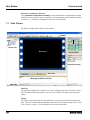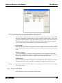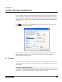
1
QLARITY FOUNDRY® USER GUIDE REVISION 2.61 QSI CORPORATION 2212 South West Temple #50 Salt Lake City, Utah 84115-2648 USA M01-005-00 Rev 3 Phone 801-466-8770 Fax 801-466-8792 Email [email protected] Web www.qsicorp.com Copyright © 2009 QSI Corporation. Printed in the USA. All rights reserved. No part of this publication may be reproduced, in any form or by any means without prior written permission from QSI Corporation. QTERM-G70, G70, QTERM-G75, G75, QTERM-G55, G55, QTERM-Z60, Z60, and QTERM are trademarks, and Qlarity and Qlarity Foundry are registered trademarks of QSI Corporation. Microsoft, Windows, Windows NT, Windows 2000, Windows XP and their respective logos are registered trademarks of Microsoft Corporation in the United States and other countries. TrueType is a registered trademark of Apple Computer, Inc. Manual Updated 13 October 2009 FCC COMPLIANCE STATEMENT This device complies with part 15 of the FCC Rules. Operation is subject to the following two conditions: (1) This device may not cause harmful interference, and (2) this device must accept any interference received, including interference that may cause undesired operation. This equipment has been tested and found to comply with the limits for a Class A digital device, pursuant to part 15 of the FCC Rules. These limits are designed to provide reasonable protection against harmful interference when the equipment is operated in a commercial environment. This equipment generates, uses, and can radiate radio frequency energy and, if not installed and used in accordance with the instruction manual, may cause harmful interference to radio communications. Operation of this equipment in a residential area is likely to cause harmful interference in which case the user will be required to correct the interference at his own expense. Any modification to this device (including any changes to the recommended antenna configuration) that are not expressly approved by QSI could void the user's authority to operate this device. FOREWORD Qlarity Foundry® is a Windows®-based design tool that uses the Qlarity® programming language to help you design user applications for a Qlarity-based terminal. Chapter 1 Introduction. This chapter explains how to use this manual to get the most out of Qlarity Foundry and describes Qlarity Foundry. Chapter 2 Installation. This chapter covers the installation and setup of the Qlarity Foundry software. Chapter 3 Getting Started. This chapter outlines Qlarity Foundry’s features and functions. Chapter 4 Workspaces. This chapter explains how to start, open, close, save, and use workspaces in Qlarity Foundry. Chapter 5 Templates, Resources, and Libraries. This chapter explains how to add and edit templates (advanced function), edit resources, and edit libraries. Chapter 6 Qlarity Foundry Preferences. This chapter explains how to set up and define your terminal settings for Qlarity Foundry and enter Qlarity Foundry preferences. Chapter 7 Download Software to the Terminal. This chapter explains how to configure the terminal communications port, download user applications and BFF files, and upgrade new firmware. Chapter 8 Basic Design. This chapter explains how to get started using Qlarity Foundry and covers user application design basics. Chapter 9 Intermediate Design. This chapter provides instructions a step beyond design basics. Chapter 10 Advanced Design. This chapter provides instructions for advanced user application design. Appendix A Glossary of Software Terms. This appendix provides definitions of the terms used in Qlarity Foundry. Appendix B AutoDoc specification. This appendix contains the complete specification on how to write AutoDoc meta data to document the source code in a workspace and Qlarity libraries. MANUAL CONVENTIONS Within Qlarity Foundry, functions can be selected using a mouse, a keyboard shortcut, or an icon on a toolbar. The following conventions are used to identify selections in this manual. When instructed to press a specific key, it is shown in a bold, sans serif typeface and is enclosed in angle brackets: <Enter> When instructed to press a key and hold it down while typing another key, the keys are shown together: <CTRL>+<V> When instructed to click a button or icon, it is shown in a bold, sans serif typeface and is enclosed in square brackets: [OK] Icons on toolbars are represented graphically: Click When instructed to type a character or a word, it is shown in the Courier typeface: e:\setup Directory paths, file names, and file name extensions are indicated by italics: eventbuilder.qly Syntax, commands, and examples are shown in the Courier typeface: dim count as integer on the toolbar. CONTENTS CHAPTER 1 INTRODUCTION . . . . . . . . . . . . . . . . . . . . . . . . . . . . . . . . . . . . . . . . . . . . . . . . . . . . . . . . . . . .1 1.1 How to Use This Manual . . . . . . . . . . . . . . . . . . . . . . . . . . . . . . . . . . . . . . . . . . . . . .1 1.2 Description . . . . . . . . . . . . . . . . . . . . . . . . . . . . . . . . . . . . . . . . . . . . . . . . . . . . . . . . .1 CHAPTER 2 INSTALLATION . . . . . . . . . . . . . . . . . . . . . . . . . . . . . . . . . . . . . . . . . . . . . . . . . . . . . . . . . . . . .3 2.1 System Requirements . . . . . . . . . . . . . . . . . . . . . . . . . . . . . . . . . . . . . . . . . . . . . . . . .3 2.2 Install Qlarity Foundry . . . . . . . . . . . . . . . . . . . . . . . . . . . . . . . . . . . . . . . . . . . . . . . .3 CHAPTER 3 GETTING STARTED . . . . . . . . . . . . . . . . . . . . . . . . . . . . . . . . . . . . . . . . . . . . . . . . . . . . . . . . .7 3.1 Start Qlarity Foundry . . . . . . . . . . . . . . . . . . . . . . . . . . . . . . . . . . . . . . . . . . . . . . . . .7 3.1.1 Hardware Configuration Assistant . . . . . . . . . . . . . . . . . . . . . . . . . . . . . . . . . .7 3.2 Open a Workspace . . . . . . . . . . . . . . . . . . . . . . . . . . . . . . . . . . . . . . . . . . . . . . . . . . .8 3.3 Main Window . . . . . . . . . . . . . . . . . . . . . . . . . . . . . . . . . . . . . . . . . . . . . . . . . . . . . .10 3.4 Menu Options . . . . . . . . . . . . . . . . . . . . . . . . . . . . . . . . . . . . . . . . . . . . . . . . . . . . . .11 3.4.1 File Menu . . . . . . . . . . . . . . . . . . . . . . . . . . . . . . . . . . . . . . . . . . . . . . . . . . . .12 3.4.2 Edit Menu . . . . . . . . . . . . . . . . . . . . . . . . . . . . . . . . . . . . . . . . . . . . . . . . . . . .13 3.4.3 View Menu . . . . . . . . . . . . . . . . . . . . . . . . . . . . . . . . . . . . . . . . . . . . . . . . . . .14 3.4.4 Tools Menu . . . . . . . . . . . . . . . . . . . . . . . . . . . . . . . . . . . . . . . . . . . . . . . . . . .15 3.4.5 Help Menu . . . . . . . . . . . . . . . . . . . . . . . . . . . . . . . . . . . . . . . . . . . . . . . . . . . .17 3.5 Toolbar . . . . . . . . . . . . . . . . . . . . . . . . . . . . . . . . . . . . . . . . . . . . . . . . . . . . . . . . . . .18 3.5.1 Layout View Toolbar . . . . . . . . . . . . . . . . . . . . . . . . . . . . . . . . . . . . . . . . . . .18 3.5.2 Code View Toolbar . . . . . . . . . . . . . . . . . . . . . . . . . . . . . . . . . . . . . . . . . . . . .20 3.5.3 Simulation View Toolbar . . . . . . . . . . . . . . . . . . . . . . . . . . . . . . . . . . . . . . . .21 3.6 Navigation Bar (Code View only) . . . . . . . . . . . . . . . . . . . . . . . . . . . . . . . . . . . . . .21 3.6.1 Global, Template, or Library Code . . . . . . . . . . . . . . . . . . . . . . . . . . . . . . . . .22 3.6.2 Object Instance Code. . . . . . . . . . . . . . . . . . . . . . . . . . . . . . . . . . . . . . . . . . . .22 3.7 Object Tree . . . . . . . . . . . . . . . . . . . . . . . . . . . . . . . . . . . . . . . . . . . . . . . . . . . . . . . .23 3.7.1 Globals. . . . . . . . . . . . . . . . . . . . . . . . . . . . . . . . . . . . . . . . . . . . . . . . . . . . . . .24 3.7.2 Internal. . . . . . . . . . . . . . . . . . . . . . . . . . . . . . . . . . . . . . . . . . . . . . . . . . . . . . .25 3.7.3 Object Templates. . . . . . . . . . . . . . . . . . . . . . . . . . . . . . . . . . . . . . . . . . . . . . .25 3.8 Layout and Code Views . . . . . . . . . . . . . . . . . . . . . . . . . . . . . . . . . . . . . . . . . . . . . .25 3.9 Simulation View . . . . . . . . . . . . . . . . . . . . . . . . . . . . . . . . . . . . . . . . . . . . . . . . . . . .26 3.9.1 Serial I/O Support . . . . . . . . . . . . . . . . . . . . . . . . . . . . . . . . . . . . . . . . . . . . . .28 3.9.2 File System Support . . . . . . . . . . . . . . . . . . . . . . . . . . . . . . . . . . . . . . . . . . . .28 3.9.3 Simulation View Limitations . . . . . . . . . . . . . . . . . . . . . . . . . . . . . . . . . . . . .29 3.9.4 Source-Level Debugger. . . . . . . . . . . . . . . . . . . . . . . . . . . . . . . . . . . . . . . . . .29 3.9.5 Call Stack Window . . . . . . . . . . . . . . . . . . . . . . . . . . . . . . . . . . . . . . . . . . . . .30 3.9.6 Watch Window . . . . . . . . . . . . . . . . . . . . . . . . . . . . . . . . . . . . . . . . . . . . . . . .30 3.10 Properties Window . . . . . . . . . . . . . . . . . . . . . . . . . . . . . . . . . . . . . . . . . . . . . . . . .31 3.11 Object Palette . . . . . . . . . . . . . . . . . . . . . . . . . . . . . . . . . . . . . . . . . . . . . . . . . . . . .33 3.11.1 Add a New Object Instance. . . . . . . . . . . . . . . . . . . . . . . . . . . . . . . . . . . . . .33 QSI Qlarity Foundry i Contents 3.12 Move and Resize Windows . . . . . . . . . . . . . . . . . . . . . . . . . . . . . . . . . . . . . . . . . .34 3.13 Where to Go From Here . . . . . . . . . . . . . . . . . . . . . . . . . . . . . . . . . . . . . . . . . . . . .35 CHAPTER 4 WORKSPACES. . . . . . . . . . . . . . . . . . . . . . . . . . . . . . . . . . . . . . . . . . . . . . . . . . . . . . . . . . . . .37 4.1 Start a New Workspace. . . . . . . . . . . . . . . . . . . . . . . . . . . . . . . . . . . . . . . . . . . . . . .37 4.2 Open a Workspace . . . . . . . . . . . . . . . . . . . . . . . . . . . . . . . . . . . . . . . . . . . . . . . . . .40 4.3 Close a Workspace . . . . . . . . . . . . . . . . . . . . . . . . . . . . . . . . . . . . . . . . . . . . . . . . . .40 4.4 Save a Workspace . . . . . . . . . . . . . . . . . . . . . . . . . . . . . . . . . . . . . . . . . . . . . . . . . . .41 4.4.1 Save Workspace . . . . . . . . . . . . . . . . . . . . . . . . . . . . . . . . . . . . . . . . . . . . . . .41 4.4.2 Save Workspace As. . . . . . . . . . . . . . . . . . . . . . . . . . . . . . . . . . . . . . . . . . . . .41 4.4.3 Collect for Output . . . . . . . . . . . . . . . . . . . . . . . . . . . . . . . . . . . . . . . . . . . . . .42 4.5 Compile a Workspace . . . . . . . . . . . . . . . . . . . . . . . . . . . . . . . . . . . . . . . . . . . . . . . .42 4.6 Generate a BFF File . . . . . . . . . . . . . . . . . . . . . . . . . . . . . . . . . . . . . . . . . . . . . . . . .43 CHAPTER 5 TEMPLATES, RESOURCES, AND LIBRARIES . . . . . . . . . . . . . . . . . . . . . . . . . . . . . . . . . . . . .45 5.1 Add/Edit Templates . . . . . . . . . . . . . . . . . . . . . . . . . . . . . . . . . . . . . . . . . . . . . . . . .45 5.1.1 Add a New Object Template . . . . . . . . . . . . . . . . . . . . . . . . . . . . . . . . . . . . . .45 5.1.2 Edit a Template Icon . . . . . . . . . . . . . . . . . . . . . . . . . . . . . . . . . . . . . . . . . . . .47 5.1.3 Rename a Template . . . . . . . . . . . . . . . . . . . . . . . . . . . . . . . . . . . . . . . . . . . . .48 5.1.4 Remove a Template. . . . . . . . . . . . . . . . . . . . . . . . . . . . . . . . . . . . . . . . . . . . .48 5.1.5 Send Template to Library . . . . . . . . . . . . . . . . . . . . . . . . . . . . . . . . . . . . . . . .49 5.1.6 Change Template Type . . . . . . . . . . . . . . . . . . . . . . . . . . . . . . . . . . . . . . . . . .49 5.1.7 Extend a Template. . . . . . . . . . . . . . . . . . . . . . . . . . . . . . . . . . . . . . . . . . . . . .50 5.2 Edit Resources . . . . . . . . . . . . . . . . . . . . . . . . . . . . . . . . . . . . . . . . . . . . . . . . . . . . .50 5.2.1 Add a Resource . . . . . . . . . . . . . . . . . . . . . . . . . . . . . . . . . . . . . . . . . . . . . . . .51 5.2.2 Preview Resources . . . . . . . . . . . . . . . . . . . . . . . . . . . . . . . . . . . . . . . . . . . . .52 5.2.3 Rename a Resource . . . . . . . . . . . . . . . . . . . . . . . . . . . . . . . . . . . . . . . . . . . . .53 5.2.4 Change a Resource File. . . . . . . . . . . . . . . . . . . . . . . . . . . . . . . . . . . . . . . . . .53 5.2.5 Remove a Resource . . . . . . . . . . . . . . . . . . . . . . . . . . . . . . . . . . . . . . . . . . . . .54 5.2.6 Bitmaps . . . . . . . . . . . . . . . . . . . . . . . . . . . . . . . . . . . . . . . . . . . . . . . . . . . . . .54 5.2.7 Fonts . . . . . . . . . . . . . . . . . . . . . . . . . . . . . . . . . . . . . . . . . . . . . . . . . . . . . . . .54 5.2.8 Audio . . . . . . . . . . . . . . . . . . . . . . . . . . . . . . . . . . . . . . . . . . . . . . . . . . . . . . . .55 5.2.9 Binary . . . . . . . . . . . . . . . . . . . . . . . . . . . . . . . . . . . . . . . . . . . . . . . . . . . . . . .55 5.3 Edit Libraries . . . . . . . . . . . . . . . . . . . . . . . . . . . . . . . . . . . . . . . . . . . . . . . . . . . . . .55 5.3.1 Add Existing Library. . . . . . . . . . . . . . . . . . . . . . . . . . . . . . . . . . . . . . . . . . . .56 5.3.2 Remove Library. . . . . . . . . . . . . . . . . . . . . . . . . . . . . . . . . . . . . . . . . . . . . . . .57 5.3.3 Edit Library . . . . . . . . . . . . . . . . . . . . . . . . . . . . . . . . . . . . . . . . . . . . . . . . . . .57 5.3.3.1 Edit Entry . . . . . . . . . . . . . . . . . . . . . . . . . . . . . . . . . . . . . . . . . . . . . .58 5.3.3.2 Rename Entry . . . . . . . . . . . . . . . . . . . . . . . . . . . . . . . . . . . . . . . . . . .60 5.3.3.3 Remove Entry . . . . . . . . . . . . . . . . . . . . . . . . . . . . . . . . . . . . . . . . . . .60 5.3.3.4 Set Entry Version . . . . . . . . . . . . . . . . . . . . . . . . . . . . . . . . . . . . . . . .60 5.3.3.5 Add New Entry . . . . . . . . . . . . . . . . . . . . . . . . . . . . . . . . . . . . . . . . . .60 5.3.4 Advanced. . . . . . . . . . . . . . . . . . . . . . . . . . . . . . . . . . . . . . . . . . . . . . . . . . . . .61 5.3.4.1 Edit Standard (natives.lib). . . . . . . . . . . . . . . . . . . . . . . . . . . . . . . . . .61 5.3.4.2 Edit Core (core.qlib.qhide) . . . . . . . . . . . . . . . . . . . . . . . . . . . . . . . . .62 ii QSI Qlarity Foundry Contents 5.3.4.3 System Libraries Not Explicitly Included in This Workspace . . . . . .63 5.3.5 Create a New Library . . . . . . . . . . . . . . . . . . . . . . . . . . . . . . . . . . . . . . . . . . .63 5.4 Edit Named Colors . . . . . . . . . . . . . . . . . . . . . . . . . . . . . . . . . . . . . . . . . . . . . . . . . .64 5.4.1 Themes . . . . . . . . . . . . . . . . . . . . . . . . . . . . . . . . . . . . . . . . . . . . . . . . . . . . . .65 5.4.2 Named Colors . . . . . . . . . . . . . . . . . . . . . . . . . . . . . . . . . . . . . . . . . . . . . . . . .66 5.4.2.1 Change Named Color . . . . . . . . . . . . . . . . . . . . . . . . . . . . . . . . . . . . .66 5.4.2.2 Create New Named Color . . . . . . . . . . . . . . . . . . . . . . . . . . . . . . . . . .66 5.4.2.3 Delete Named Color . . . . . . . . . . . . . . . . . . . . . . . . . . . . . . . . . . . . . .67 5.4.2.4 Rename Named Color . . . . . . . . . . . . . . . . . . . . . . . . . . . . . . . . . . . . .67 5.4.2.5 Reset Color to Theme Default. . . . . . . . . . . . . . . . . . . . . . . . . . . . . . .67 5.5 Edit Named Borders . . . . . . . . . . . . . . . . . . . . . . . . . . . . . . . . . . . . . . . . . . . . . . . . .67 5.5.1 Themes . . . . . . . . . . . . . . . . . . . . . . . . . . . . . . . . . . . . . . . . . . . . . . . . . . . . . .68 5.5.2 Named Borders . . . . . . . . . . . . . . . . . . . . . . . . . . . . . . . . . . . . . . . . . . . . . . . .69 5.5.2.1 General Effects . . . . . . . . . . . . . . . . . . . . . . . . . . . . . . . . . . . . . . . . . .69 5.5.2.2 Rounded Corners. . . . . . . . . . . . . . . . . . . . . . . . . . . . . . . . . . . . . . . . .70 5.5.2.3 Double Border . . . . . . . . . . . . . . . . . . . . . . . . . . . . . . . . . . . . . . . . . . .70 5.5.2.4 Preview . . . . . . . . . . . . . . . . . . . . . . . . . . . . . . . . . . . . . . . . . . . . . . . .70 5.5.2.5 Create New Named Border . . . . . . . . . . . . . . . . . . . . . . . . . . . . . . . . .70 5.5.2.6 Delete Named Border . . . . . . . . . . . . . . . . . . . . . . . . . . . . . . . . . . . . .70 5.5.2.7 Rename Named Border . . . . . . . . . . . . . . . . . . . . . . . . . . . . . . . . . . . .71 5.5.2.8 Reset Border to Default. . . . . . . . . . . . . . . . . . . . . . . . . . . . . . . . . . . .71 CHAPTER 6 QLARITY FOUNDRY PREFERENCES . . . . . . . . . . . . . . . . . . . . . . . . . . . . . . . . . . . . . . . . . . .73 6.1 Terminal . . . . . . . . . . . . . . . . . . . . . . . . . . . . . . . . . . . . . . . . . . . . . . . . . . . . . . . . . .73 6.1.1 Display Setup . . . . . . . . . . . . . . . . . . . . . . . . . . . . . . . . . . . . . . . . . . . . . . . . .74 6.1.2 Input. . . . . . . . . . . . . . . . . . . . . . . . . . . . . . . . . . . . . . . . . . . . . . . . . . . . . . . . .75 6.1.3 Communications . . . . . . . . . . . . . . . . . . . . . . . . . . . . . . . . . . . . . . . . . . . . . . .75 6.1.4 Miscellaneous . . . . . . . . . . . . . . . . . . . . . . . . . . . . . . . . . . . . . . . . . . . . . . . . .75 6.2 Layout . . . . . . . . . . . . . . . . . . . . . . . . . . . . . . . . . . . . . . . . . . . . . . . . . . . . . . . . . . . .75 6.3 Editor. . . . . . . . . . . . . . . . . . . . . . . . . . . . . . . . . . . . . . . . . . . . . . . . . . . . . . . . . . . . .77 6.3.1 Colors . . . . . . . . . . . . . . . . . . . . . . . . . . . . . . . . . . . . . . . . . . . . . . . . . . . . . . .78 6.3.2 Font . . . . . . . . . . . . . . . . . . . . . . . . . . . . . . . . . . . . . . . . . . . . . . . . . . . . . . . . .79 6.3.3 Tab Spacing . . . . . . . . . . . . . . . . . . . . . . . . . . . . . . . . . . . . . . . . . . . . . . . . . . .79 6.3.4 Show Advanced Code Sections in Object Tree. . . . . . . . . . . . . . . . . . . . . . . .79 6.3.5 Fast Selection . . . . . . . . . . . . . . . . . . . . . . . . . . . . . . . . . . . . . . . . . . . . . . . . .79 6.3.6 Parenthesis Matching . . . . . . . . . . . . . . . . . . . . . . . . . . . . . . . . . . . . . . . . . . .79 6.3.7 Edit Events in the Event Builder . . . . . . . . . . . . . . . . . . . . . . . . . . . . . . . . . . .80 6.3.8 AutoHelp Settings . . . . . . . . . . . . . . . . . . . . . . . . . . . . . . . . . . . . . . . . . . . . . .80 6.3.8.1 Functions and Methods . . . . . . . . . . . . . . . . . . . . . . . . . . . . . . . . . . . .80 6.3.8.2 Identifier Completion . . . . . . . . . . . . . . . . . . . . . . . . . . . . . . . . . . . . .81 6.3.8.3 Assignment and Parameters . . . . . . . . . . . . . . . . . . . . . . . . . . . . . . . .81 6.3.8.4 Show Global Variables and Functions . . . . . . . . . . . . . . . . . . . . . . . .81 6.3.8.5 Show Object Properties and Methods . . . . . . . . . . . . . . . . . . . . . . . . .82 6.3.8.6 Show for Built In Data Types . . . . . . . . . . . . . . . . . . . . . . . . . . . . . . .82 6.3.8.7 Fade AutoHelp Tips . . . . . . . . . . . . . . . . . . . . . . . . . . . . . . . . . . . . . .82 6.4 Compile. . . . . . . . . . . . . . . . . . . . . . . . . . . . . . . . . . . . . . . . . . . . . . . . . . . . . . . . . . .82 QSI Qlarity Foundry iii Contents 6.5 Simulation View . . . . . . . . . . . . . . . . . . . . . . . . . . . . . . . . . . . . . . . . . . . . . . . . . . . .83 6.5.1 Communications Window Settings . . . . . . . . . . . . . . . . . . . . . . . . . . . . . . . . .84 6.5.2 Keypad Settings. . . . . . . . . . . . . . . . . . . . . . . . . . . . . . . . . . . . . . . . . . . . . . . .86 6.5.3 Serial Port Setup . . . . . . . . . . . . . . . . . . . . . . . . . . . . . . . . . . . . . . . . . . . . . . .87 CHAPTER 7 DOWNLOAD SOFTWARE TO THE TERMINAL . . . . . . . . . . . . . . . . . . . . . . . . . . . . . . . . . . . .89 7.1 Configure Communications Port . . . . . . . . . . . . . . . . . . . . . . . . . . . . . . . . . . . . . . .89 7.1.1 Serial Port Settings . . . . . . . . . . . . . . . . . . . . . . . . . . . . . . . . . . . . . . . . . . . . .90 7.1.2 Ethernet Port Settings . . . . . . . . . . . . . . . . . . . . . . . . . . . . . . . . . . . . . . . . . . .90 7.2 Download a User Application. . . . . . . . . . . . . . . . . . . . . . . . . . . . . . . . . . . . . . . . . .91 7.2.1 Prepare the Terminal for Downloading. . . . . . . . . . . . . . . . . . . . . . . . . . . . . .91 7.2.2 Download the User Application . . . . . . . . . . . . . . . . . . . . . . . . . . . . . . . . . . .91 7.3 Download a BFF File . . . . . . . . . . . . . . . . . . . . . . . . . . . . . . . . . . . . . . . . . . . . . . . .92 7.4 Upgrade the Firmware . . . . . . . . . . . . . . . . . . . . . . . . . . . . . . . . . . . . . . . . . . . . . . .94 7.4.1 Determine Current Firmware Version. . . . . . . . . . . . . . . . . . . . . . . . . . . . . . .94 7.4.2 Prepare Terminal for Upgrade. . . . . . . . . . . . . . . . . . . . . . . . . . . . . . . . . . . . .95 7.4.3 Download New Firmware . . . . . . . . . . . . . . . . . . . . . . . . . . . . . . . . . . . . . . . .95 7.4.4 Induce Bootloader . . . . . . . . . . . . . . . . . . . . . . . . . . . . . . . . . . . . . . . . . . . . . .96 7.4.5 Set Unit Time . . . . . . . . . . . . . . . . . . . . . . . . . . . . . . . . . . . . . . . . . . . . . . . . .97 CHAPTER 8 BASIC DESIGN . . . . . . . . . . . . . . . . . . . . . . . . . . . . . . . . . . . . . . . . . . . . . . . . . . . . . . . . . . . .99 8.1 Prepare Qlarity Foundry for Application Design . . . . . . . . . . . . . . . . . . . . . . . . . .100 8.1.1 Basic Design Layout . . . . . . . . . . . . . . . . . . . . . . . . . . . . . . . . . . . . . . . . . . .100 8.1.2 Simulate the Terminal Display . . . . . . . . . . . . . . . . . . . . . . . . . . . . . . . . . . .101 8.1.3 Drawing Aids . . . . . . . . . . . . . . . . . . . . . . . . . . . . . . . . . . . . . . . . . . . . . . . .102 8.1.4 Add/Remove Resources . . . . . . . . . . . . . . . . . . . . . . . . . . . . . . . . . . . . . . . .103 8.1.5 Add/Remove Libraries . . . . . . . . . . . . . . . . . . . . . . . . . . . . . . . . . . . . . . . . .104 8.1.5.1 Libraries Provided with Qlarity Foundry . . . . . . . . . . . . . . . . . . . . .105 8.2 Understanding Qlarity for Basic Design. . . . . . . . . . . . . . . . . . . . . . . . . . . . . . . . .106 8.2.1 Workspaces and User Applications. . . . . . . . . . . . . . . . . . . . . . . . . . . . . . . .106 8.2.2 Qlarity Objects . . . . . . . . . . . . . . . . . . . . . . . . . . . . . . . . . . . . . . . . . . . . . . .106 8.2.3 Parent/Child Relationships . . . . . . . . . . . . . . . . . . . . . . . . . . . . . . . . . . . . . .107 8.2.4 Z-Order . . . . . . . . . . . . . . . . . . . . . . . . . . . . . . . . . . . . . . . . . . . . . . . . . . . . .109 8.2.5 Events and Messaging . . . . . . . . . . . . . . . . . . . . . . . . . . . . . . . . . . . . . . . . . .109 8.2.6 Enabled/Disabled Objects . . . . . . . . . . . . . . . . . . . . . . . . . . . . . . . . . . . . . . .109 8.3 Design a User Application . . . . . . . . . . . . . . . . . . . . . . . . . . . . . . . . . . . . . . . . . . .110 8.3.1 Add an Object Instance . . . . . . . . . . . . . . . . . . . . . . . . . . . . . . . . . . . . . . . . .110 8.3.1.1 Add an Object From the Object Palette . . . . . . . . . . . . . . . . . . . . . .110 8.3.1.2 Add an Object From the Shortcut Menu . . . . . . . . . . . . . . . . . . . . . .111 8.3.2 Move, Resize and Reorder Objects . . . . . . . . . . . . . . . . . . . . . . . . . . . . . . . .112 8.3.2.1 Move an Object . . . . . . . . . . . . . . . . . . . . . . . . . . . . . . . . . . . . . . . . .112 8.3.2.2 Resize an Object . . . . . . . . . . . . . . . . . . . . . . . . . . . . . . . . . . . . . . . .112 8.3.2.3 Change the Order of Objects. . . . . . . . . . . . . . . . . . . . . . . . . . . . . . .112 8.3.2.4 Align/Size/Space Objects . . . . . . . . . . . . . . . . . . . . . . . . . . . . . . . . .113 8.3.3 Change an Object’s Properties . . . . . . . . . . . . . . . . . . . . . . . . . . . . . . . . . . .115 iv QSI Qlarity Foundry Contents 8.3.3.1 Select Color . . . . . . . . . . . . . . . . . . . . . . . . . . . . . . . . . . . . . . . . . . . .117 8.4 Event Builder . . . . . . . . . . . . . . . . . . . . . . . . . . . . . . . . . . . . . . . . . . . . . . . . . . . . .119 8.4.1 Overview of Event Builder Steps . . . . . . . . . . . . . . . . . . . . . . . . . . . . . . . . .119 8.4.2 Event Builder Dialog Box . . . . . . . . . . . . . . . . . . . . . . . . . . . . . . . . . . . . . . .120 8.4.3 Select and Configure Actions . . . . . . . . . . . . . . . . . . . . . . . . . . . . . . . . . . . .122 8.4.3.1 Select Actions . . . . . . . . . . . . . . . . . . . . . . . . . . . . . . . . . . . . . . . . . .122 8.4.3.2 Configure Actions . . . . . . . . . . . . . . . . . . . . . . . . . . . . . . . . . . . . . . .123 8.4.4 Load Event Builder Sample Workspace . . . . . . . . . . . . . . . . . . . . . . . . . . . .126 8.4.4.1 Tank Demo . . . . . . . . . . . . . . . . . . . . . . . . . . . . . . . . . . . . . . . . . . . .127 8.4.4.2 Toggle Demo. . . . . . . . . . . . . . . . . . . . . . . . . . . . . . . . . . . . . . . . . . .127 8.4.4.3 Keypad Demo . . . . . . . . . . . . . . . . . . . . . . . . . . . . . . . . . . . . . . . . . .128 8.4.5 Qlarity Code and Event Builder . . . . . . . . . . . . . . . . . . . . . . . . . . . . . . . . . .128 8.4.6 Troubleshooting. . . . . . . . . . . . . . . . . . . . . . . . . . . . . . . . . . . . . . . . . . . . . . .128 8.5 Communication Objects . . . . . . . . . . . . . . . . . . . . . . . . . . . . . . . . . . . . . . . . . . . . .129 8.5.1 Serial Objects . . . . . . . . . . . . . . . . . . . . . . . . . . . . . . . . . . . . . . . . . . . . . . . .129 8.5.2 Ethernet Objects . . . . . . . . . . . . . . . . . . . . . . . . . . . . . . . . . . . . . . . . . . . . . .129 8.5.3 Receive Data . . . . . . . . . . . . . . . . . . . . . . . . . . . . . . . . . . . . . . . . . . . . . . . . .131 8.6 Test the User Application . . . . . . . . . . . . . . . . . . . . . . . . . . . . . . . . . . . . . . . . . . . .131 8.7 Save and Compile a Workspace . . . . . . . . . . . . . . . . . . . . . . . . . . . . . . . . . . . . . . .132 8.7.1 Save a Workspace . . . . . . . . . . . . . . . . . . . . . . . . . . . . . . . . . . . . . . . . . . . . .132 8.7.2 Compile a Workspace . . . . . . . . . . . . . . . . . . . . . . . . . . . . . . . . . . . . . . . . . .132 8.8 Download a User Application. . . . . . . . . . . . . . . . . . . . . . . . . . . . . . . . . . . . . . . . .132 CHAPTER 9 INTERMEDIATE DESIGN. . . . . . . . . . . . . . . . . . . . . . . . . . . . . . . . . . . . . . . . . . . . . . . . . . . .133 9.1 Viewing the Code . . . . . . . . . . . . . . . . . . . . . . . . . . . . . . . . . . . . . . . . . . . . . . . . . .134 9.2 Understanding Qlarity for Intermediate Design . . . . . . . . . . . . . . . . . . . . . . . . . . .134 9.2.1 Qlarity Programming Language . . . . . . . . . . . . . . . . . . . . . . . . . . . . . . . . . .135 9.2.2 Objects and Templates . . . . . . . . . . . . . . . . . . . . . . . . . . . . . . . . . . . . . . . . .135 9.3 Qlarity Code for Objects . . . . . . . . . . . . . . . . . . . . . . . . . . . . . . . . . . . . . . . . . . . . .135 9.3.1 Property Initializations . . . . . . . . . . . . . . . . . . . . . . . . . . . . . . . . . . . . . . . . .135 9.3.2 Method Overrides . . . . . . . . . . . . . . . . . . . . . . . . . . . . . . . . . . . . . . . . . . . . .136 9.4 Handling Events With Qlarity Code . . . . . . . . . . . . . . . . . . . . . . . . . . . . . . . . . . . .136 9.4.1 Override an Object Method . . . . . . . . . . . . . . . . . . . . . . . . . . . . . . . . . . . . . .137 9.5 Global Code . . . . . . . . . . . . . . . . . . . . . . . . . . . . . . . . . . . . . . . . . . . . . . . . . . . . . .138 9.5.1 Add a Global Variable to a Workspace. . . . . . . . . . . . . . . . . . . . . . . . . . . . .139 9.5.1.1 Add a Global Variable Using New Variable. . . . . . . . . . . . . . . . . . .139 9.5.1.2 Add a Global Variable in the Global Code Section . . . . . . . . . . . . .140 9.5.2 Add a Global Function to a Workspace . . . . . . . . . . . . . . . . . . . . . . . . . . . .140 9.5.3 Add a Global Message Handler to a Workspace. . . . . . . . . . . . . . . . . . . . . .141 9.5.3.1 Add a Global Message Handler From a List. . . . . . . . . . . . . . . . . . .142 9.5.3.2 Add a Global Message Handler in the Global Code Section . . . . . .142 9.6 Create a New Object Template . . . . . . . . . . . . . . . . . . . . . . . . . . . . . . . . . . . . . . . .144 9.7 Where to Go From Here . . . . . . . . . . . . . . . . . . . . . . . . . . . . . . . . . . . . . . . . . . . . .146 CHAPTER 10 QSI Qlarity Foundry v Contents ADVANCED DESIGN . . . . . . . . . . . . . . . . . . . . . . . . . . . . . . . . . . . . . . . . . . . . . . . . . . . . . . .147 10.1 Advanced Code Sections . . . . . . . . . . . . . . . . . . . . . . . . . . . . . . . . . . . . . . . . . . .147 10.1.1 Advanced Code . . . . . . . . . . . . . . . . . . . . . . . . . . . . . . . . . . . . . . . . . . . . . .148 10.1.2 Libraries. . . . . . . . . . . . . . . . . . . . . . . . . . . . . . . . . . . . . . . . . . . . . . . . . . . .148 10.2 Validation Functions. . . . . . . . . . . . . . . . . . . . . . . . . . . . . . . . . . . . . . . . . . . . . . .148 10.3 The Qlarity API Library . . . . . . . . . . . . . . . . . . . . . . . . . . . . . . . . . . . . . . . . . . . .149 10.4 Exception Handling . . . . . . . . . . . . . . . . . . . . . . . . . . . . . . . . . . . . . . . . . . . . . . .150 10.5 Create a New Object Template . . . . . . . . . . . . . . . . . . . . . . . . . . . . . . . . . . . . . . .152 10.5.1 New Template Boilerplate Code . . . . . . . . . . . . . . . . . . . . . . . . . . . . . . . . .154 10.5.1.1 Non-Drawable Objects . . . . . . . . . . . . . . . . . . . . . . . . . . . . . . . . . .156 10.5.1.2 Area Objects . . . . . . . . . . . . . . . . . . . . . . . . . . . . . . . . . . . . . . . . . .156 10.5.1.3 Container Objects . . . . . . . . . . . . . . . . . . . . . . . . . . . . . . . . . . . . . .158 10.5.2 Getting New Object Templates to Work in Qlarity Foundry . . . . . . . . . . .158 10.5.3 Adding Object Template Documentation . . . . . . . . . . . . . . . . . . . . . . . . . .165 10.6 Guidelines for Designing New Object Templates . . . . . . . . . . . . . . . . . . . . . . . .167 10.7 Where to Go From Here . . . . . . . . . . . . . . . . . . . . . . . . . . . . . . . . . . . . . . . . . . . .168 APPENDIX A GLOSSARY OF SOFTWARE TERMS . . . . . . . . . . . . . . . . . . . . . . . . . . . . . . . . . . . . . . . . . . .169 APPENDIX B AUTODOC SPECIFICATION . . . . . . . . . . . . . . . . . . . . . . . . . . . . . . . . . . . . . . . . . . . . . . . . .173 B.1 Documentation Declaration . . . . . . . . . . . . . . . . . . . . . . . . . . . . . . . . . . . . . . . . . .173 B.2 Documentation Body . . . . . . . . . . . . . . . . . . . . . . . . . . . . . . . . . . . . . . . . . . . . . . .174 B.3 Linking Items . . . . . . . . . . . . . . . . . . . . . . . . . . . . . . . . . . . . . . . . . . . . . . . . . . . . .174 B.4 Importing Items . . . . . . . . . . . . . . . . . . . . . . . . . . . . . . . . . . . . . . . . . . . . . . . . . . .175 B.5 Function Parameters. . . . . . . . . . . . . . . . . . . . . . . . . . . . . . . . . . . . . . . . . . . . . . . .176 B.6 Data Type Elements . . . . . . . . . . . . . . . . . . . . . . . . . . . . . . . . . . . . . . . . . . . . . . . .176 B.7 Grouping Items. . . . . . . . . . . . . . . . . . . . . . . . . . . . . . . . . . . . . . . . . . . . . . . . . . . .177 B.8 Hiding Documentation . . . . . . . . . . . . . . . . . . . . . . . . . . . . . . . . . . . . . . . . . . . . . .177 B.9 Property Flags . . . . . . . . . . . . . . . . . . . . . . . . . . . . . . . . . . . . . . . . . . . . . . . . . . . .178 B.10 Sample Code . . . . . . . . . . . . . . . . . . . . . . . . . . . . . . . . . . . . . . . . . . . . . . . . . . . .179 B.11 Property Categories . . . . . . . . . . . . . . . . . . . . . . . . . . . . . . . . . . . . . . . . . . . . . . .179 B.12 Default Items . . . . . . . . . . . . . . . . . . . . . . . . . . . . . . . . . . . . . . . . . . . . . . . . . . . .179 B.13 Defining Border Styles. . . . . . . . . . . . . . . . . . . . . . . . . . . . . . . . . . . . . . . . . . . . .180 B.14 Defining Named Colors . . . . . . . . . . . . . . . . . . . . . . . . . . . . . . . . . . . . . . . . . . . .180 vi QSI Qlarity Foundry CHAPTER 1 INTRODUCTION 1.1 How to Use This Manual For instructions on installing Qlarity Foundry, see Chapter 2, “Installation.” To get started using Qlarity Foundry and to learn design basics, review the following chapters: Chapter 3, “Getting Started” Chapter 8, “Basic Design” To learn more about user application design, refer to the following chapters: Chapter 9, “Intermediate Design” Chapter 10, “Advanced Design” Use the following chapters to learn about specific Qlarity Foundry functions: Chapter 4, “Workspaces” How to start, open, close, save, and use workspaces in Qlarity Foundry. Chapter 5, “Templates, Resources, and Libraries” How to add and edit templates (advanced function), edit resources, and edit libraries. Chapter 6, “Qlarity Foundry Preferences” How to set up and define your terminal settings for Qlarity Foundry and enter Qlarity Foundry preferences. Chapter 7, “Download Software to the Terminal” How to configure the terminal communications port, download user applications and BFF files, and upgrade new firmware. Appendix A, “Glossary of Software Terms” A list of Qlarity terms and their definitions. You should read and understand these terms before you attempt to perform the functions described in Chapter 9 and Chapter 10. 1.2 Description Qlarity (pronounced “clarity”), the programming language used to program the Qlarity-based terminal, is a powerful, BASIC-like language that utilizes the full potential of the Qlarity-based terminal. Qlarity Foundry is a Windows-based design tool that uses Qlarity to help you design user applications for the Qlarity-based terminal. QSI Qlarity Foundry 1 Description Introduction Qlarity uses “objects” as the building blocks for all user applications. An object can take many forms, including text labels and fields, bitmaps, lines, forms, key definitions, clocks, counters, and so on. Libraries, which are supplied with Qlarity Foundry, contain predefined objects for which the programming is already done. To adapt a library object to a user application, you typically only need to enter properties (e.g., name, location, color, bitmap, etc.). If custom programming is required, Qlarity Foundry contains the tools you need to modify library objects or create your own objects. Qlarity Foundry provides all the tools you need to work with user applications, including those used to do the following: • Create a user application (basic to advanced levels). • Modify a user application. • Compile and download a user application to the Qlarity-based terminal. 2 QSI Qlarity Foundry CHAPTER 2 INSTALLATION This chapter provides instructions for installing and setting up the Qlarity Foundry software. 2.1 System Requirements Computer Requirements: • 500 MHz processor or faster • 256 Mbytes of RAM (1 Gbyte recommended) • 70 Mbytes available hard disk space Operating System Requirements: Microsoft® Windows® XP or later 2.2 Install Qlarity Foundry To install Qlarity Foundry, take the following steps. 1. Close any open Windows applications. 2. Insert the Qlarity Foundry CD-ROM into your CD-ROM drive. The Setup program should auto-start. If it does not auto-start, click [Start], and click Run. The following window appears. Type e:\setup (in which “e” is the letter of your CD-ROM drive). The following message appears as the installer is configured. QSI Qlarity Foundry 3 Install Qlarity Foundry Installation The InstallShield Wizard is loaded, and the following window appears. 3. Click [Next], and the License Agreement window is displayed. 4 QSI Qlarity Foundry Installation Install Qlarity Foundry 4. Read the agreement and click [Yes] if you accept the terms. The following window appears. 5. Accept the destination folder shown, or click [Browse] to select a different folder or create a new folder in which to install Qlarity Foundry. Click [Next] to continue. The following window appears. 6. Click each type of system setup to read a description of the files that are installed. Then, select the type of setup that best suits your needs: Complete, Custom, Minimal, or Typical. Click [Next] to continue. If you selected “Custom,” a dialog box appears for you to select the files and features you want to install. QSI Qlarity Foundry 5 Install Qlarity Foundry Installation The Setup Status window appears and displays the status of the installation as each file is installed in the specified destination folder. After all of the files are copied to your hard disk, the following window appears. 7. Click [Finish]. Installation is complete. 6 QSI Qlarity Foundry CHAPTER 3 GETTING STARTED 3.1 Start Qlarity Foundry To start Qlarity Foundry, click [Start], then click Programs and select QSI Corporation. Click Launch Qlarity Foundry to start the program. 3.1.1 Hardware Configuration Assistant The first time you launch Qlarity Foundry, the Hardware Configuration Assistant is displayed. To display the Hardware Configuration Assistant thereafter, click [Hardware Configuration Assistant] at the Welcome to Qlarity Foundry dialog box (see section 3.2, “Open a Workspace”). Use the Hardware Configuration Assistant to specify the type of terminal you are programming and to describe its hardware configuration and orientation. QSI Qlarity Foundry 7 Open a Workspace Getting Started Select Terminal Type Select the type of terminal you will be programming from the list of terminal types or by clicking its image on the left. The options available at the remaining fields are determined by the type of terminal selected. Display Select one of the following options from the drop-down list to indicate the type of display on your terminal: Color TFT or Color Enhanced TFT. Orientation Select the orientation in which your terminal is mounted: Portrait (longest dimension is vertical) or Landscape (longest dimension is horizontal). Portrait II and Landscape II options are also available to match the settings on your terminal if applicable. Serial Ports Select the number of serial communication ports on the terminal from the drop-down list. Only valid entries are listed. PS/2 Keyboard If the terminal has a keyboard port and you will be using a keyboard, select this option to enable the keyboard port. Ethernet If the terminal has an Ethernet port and you will be using it for communication, select this option to enable the port. Audio Decoder If the terminal has the audio decoder option, which allows it to play waveform audio files, you can select this option to enable it. Click [OK] to save the terminal configuration and close the window. Click [Cancel] to exit the window without saving your changes. 3.2 Open a Workspace A workspace is a file created in Qlarity Foundry that you will compile into a user application. In Qlarity Foundry, you use the workspace to define functions for the terminal; at the Qlarity-based terminal, you use the user application to perform the functions. When Qlarity Foundry starts, a dialog box appears so you can open a workspace. 8 QSI Qlarity Foundry Getting Started Open a Workspace Filter Recent If you have a long list of recent files, you can filter them to make it easier to find a file. Begin typing the name of the file, and files beginning with the characters you typed are listed. Open Selected Recently opened files, if any, are listed. To open a recent file, click the file name to select it, then click [Open Selected] (or double-click the file name). The workspace is opened in the main window. Only one workspace at a time can be open in Qlarity Foundry. Open Other File Click [Open Other File] and the Open dialog box appears showing workspaces in the default folder. Use the Windows tools to change folders if necessary. Click a file to select it, then click [Open]. The workspace is opened in the main window (see next page). Start New To start a new workspace, click [Start New]. The New Qlarity Project dialog box appears. Refer to section 4.1, “Start a New Workspace” for information. Tutorials Click [Tutorials] to open a sample workspace and to start a tutorial to help you learn the basics of Qlarity Foundry. The Object Documentation Help file is opened with the list of tutorials displayed. Click the tutorial you want to work, and the tutorial (.pdf file) is opened in Adobe Acrobat. Read through the tutorial and follow the instructions using the sample workspace. Begin editing in Layout View If this option is enabled, a workspace is automatically compiled and shown in the “Layout View” when it is opened. If disabled, the workspace is displayed in “Code View” and will need to be compiled before it can be displayed in Layout View. You can also change this setting using the Settings function, Compile tab (see section 6.4, “Compile”). QSI Qlarity Foundry 9 Main Window Getting Started Hardware Configuration Assistant Click [Hardware Configuration Assistant] to access the Hardware Configuration Assistant, which you use to specify the type of terminal you are programming and to configure it. Refer to section 3.1.1, “Hardware Configuration Assistant” for information. 3.3 Main Window The Qlarity Foundry main window is shown below. Menu Bar Toolbar Object Tree Work Area Object Palette Properties window View Tabs Messages and Errors window Status Bar Menu Bar The menu bar contains the File, Edit, View, Tools, and Help menus. Refer to section 3.4 for a brief description of the menu options. You can access all Qlarity Foundry options from the menus. Toolbar The toolbar contains tools that provide quick links to commonly used Qlarity Foundry functions. The tools available change depending on the selected view mode (Layout View or Code View). Refer to section 3.5 for a description of each tool on the toolbar. 10 QSI Qlarity Foundry Getting Started Menu Options Object Tree Object instances that have been added to the workspace are listed under “Globals” and object templates are listed under “Templates” in the Object Tree. Some objects may be automatically added to a workspace when it is created, including the following: • ScreenSaver—blanks the screen after a period of inactivity • ExceptionDisplay—displays unhandled Qlarity Exceptions Work Area This is the area in Layout View in which you place object instances to add them to the workspace. The work area simulates the display of the Qlarity-based terminal. Object Palette The Object Palette contains an icon for each object template in the workspace and in any active libraries. You click the icons to add new object instances. Move the mouse pointer over an icon to display the object’s name. Refer to section 3.11 for more information. Properties Window The Properties window is displayed by default. Click an object instance in the Object Tree or work area and its properties are displayed. Refer to section 3.10 for information. View Tabs To set up the workspace, you can work in either Layout View or Code View. Layout View is a graphics mode used to lay out the terminal display. Generally, unless you are making changes to the programming code, you will work in Layout View. Code View is used to write or edit an object’s programming code. You will generally only work in Code View if you are customizing objects or creating your own objects. Simulation View can be used after you have created a workspace to simulate the performance of the workspace objects on the Qlarity-based terminal. Click the Layout View tab or Code View tab at the bottom of the work area (default location) to change views. Click the Simulation View tab to start the terminal simulation. Refer to section 3.8 for more information on the Layout and Code Views. Refer to section 3.9 for more information on Simulation View. Messages and Errors Window The Messages and Errors window displays any errors or other messages generated when the workspace is compiled or during a “debug” operation. These messages can help you identify and correct problems with the workspace. Status Bar The status bar shows the status of the workspace and the coordinates at which the mouse pointer is positioned in the work area. Also, if you position the mouse pointer over an option on a menu or a tool on the toolbar, the function of the option or tool is displayed in the status bar. 3.4 Menu Options QSI Qlarity Foundry 11 Menu Options Getting Started The following sections describe the options available on each menu on the menu bar. 3.4.1 File Menu New Workspace Use this option to start a new workspace. Refer to section 4.1 for information. Open Workspace Use this option to open an existing workspace. Refer to section 4.2 for information. Close Workspace Select this option to close the current workspace and open a new workspace. Revert Workspace Select this option to discard any changes made to the workspace and restore it to the last saved state. Save Workspace Use this option to save the current workspace. Refer to section 4.4 for information. Save Workspace As Select this option to save a copy of the current workspace to a different file name. The Save As dialog box is displayed. Enter the new file name (the extension is added automatically), and click [Save]. Collect for Output Use this option to transfer a workspace to another computer See section 4.4.3 for information. Compile (Layout and Code View only) Use this option to compile the current workspace into the format required for a user application. A workspace must also be compiled to properly display in Layout View. Refer to section 4.5 for information on compiling a workspace. Generate BFF File (Layout and Code View only) You can download a user application that is not currently loaded in Qlarity Foundry to the Qlarity-based terminal, but the file must be in binary file format (BFF). Use this option to save a file to BFF. Refer to section 4.6 for information. Download Application (Layout and Code View only) Select this option to download files to the Qlarity-based terminal. You can download the currently loaded workspace, any BFF file, or a firmware upgrade. Refer to Chapter 7, “Download Software to the Terminal” for information. Recent Files After you have created and saved Qlarity files, you can use this option as a shortcut to open a file that was recently opened. Click Recent Files, and a list of previously opened files is displayed. Click the file that you want to open. 12 QSI Qlarity Foundry Getting Started Menu Options Exit Select this option to exit Qlarity Foundry. 3.4.2 Edit Menu The options in the Edit menu change depending on whether you are in Layout View or Code View. (The Edit menu is not available in Simulation View.) Select All (Code View only) Select this option to select all code in the Code View window. Cut In Layout View, select an object in the work area, then select this option (or press <Ctrl>+<X>) to cut the object from the workspace. In Code View, select code, then select this option (or press <Ctrl>+<X>) to cut the selected code from the workspace. The object or code remains on the Windows clipboard until replaced by another “cut” or “copy” operation. Copy In Layout View, select an object in the work area, then select this option (or press <Ctrl>+<C>) to make a copy of the object. In Code View, select code, then select this option (or press <Ctrl>+<C>) to copy the selected code. The object or code remains on the Windows clipboard until replaced by another “cut” or “copy” operation. Paste In Layout View, select this option (or press <Ctrl>+<V>) to place a cut or copied object in a new location in the same workspace or in a different workspace. In Code View, select this option (or press <Ctrll>+<V>) to place cut or copied code at the cursor position in the same or a different workspace or in a different Windows application. Find (Code View only) Select this option to find code in the displayed object instance, template, or workspace. Enter the characters or code you want to find, and click [Find Next]. To find only characters matching the entered case (upper or lower), select Match Case. To search through all object instances and templates in the workspace, select Entire Workspace. Replace (Code View only) Select this option to find code in the displayed object instance or template and replace it with specified code. In the “Find What” field, enter the characters or code you want to find. In the “Replace With” field, enter the code with which you want to replace it. Click [Find Next] to find the code. Then click [Replace] to replace it. Or, click [Replace All] to automatically find and replace all occurrences of the code. To find only characters matching the entered case (upper or lower), select Match Case. Undo Select this option to undo the last action performed. QSI Qlarity Foundry 13 Menu Options Getting Started Redo (Code View only) Select this option to redo the most recent undone action. This option is only available after you have selected Undo in Code View. Go to Bookmark (Code View only) Select this option to go to the next bookmark in the displayed object’s code. Use Set Bookmark to add or remove bookmarks in an object’s code. Set Bookmark (Code View only) Select this option to add or remove a bookmark in an object’s code at the cursor location. Bookmarks make it possible to find a location quickly, which is useful in objects with several lines of code. Go to Next Message (Code View only) If there are messages in the Messages and Errors window, select this option to select the next message (or the first one if none is selected) and position the cursor on the line that generated the message. This applies to messages due to compile errors, compile warnings, or runtime messages generated by the Tool_Trace API and runtime exceptions. Add/Edit Templates Select this option to open the Add/Edit Templates dialog box to add or edit an object template. Refer to section 5.1, “Add/Edit Templates” and to Chapter 10, “Advanced Design” for information on creating templates. Edit Resources Use this option to open the Qlarity Resources dialog box to add resources to or remove them from the workspace. Refer to section 5.2, “Edit Resources” for information. Edit Libraries Use this option to open the Libraries dialog box to add libraries to or remove libraries from the workspace. Refer to section 5.3 for information. Edit Named Colors (Layout View only) Select this option to define “named colors.” You assign named colors to objects to specify the object’s background and foreground colors. Refer to section 5.4 for information. Edit Named Borders (Layout View only) Select this option to define “named borders.” You assign named borders to objects to specify border attributes. Refer to section 5.5 for information. 3.4.3 View Menu Toolbar Select this option to show or hide the toolbar. Refer to section 3.5 for information. Status Bar Select this option to show or hide the status bar at the bottom of the main window. 14 QSI Qlarity Foundry Getting Started Menu Options Control Windows Select this option and a sub-menu is displayed listing the windows and palettes that are available in the current view. Select an option from the sub-menu to display or hide the specified window or palette. Refresh (Layout View and Simulation View only) Select this option to redraw the graphics on the screen in Layout View. Layout View Select this option to switch to Layout View. Code View Select this option to switch to Code View. Simulation View Select this option to switch to Simulation View. 3.4.4 Tools Menu View Only Enabled Objects (Layout View only) Disabled objects are displayed in Layout View by default. Select this option if you want to see only enabled objects in the work area. NOTE ☞ Keep in mind that the “enable/disable” option is different from the “show/hide” option. Disabled objects are not displayed on the Qlarity-based terminal; hidden objects are displayed on the terminal (unless they are disabled), they are only hidden in Qlarity Foundry. Refer to section 3.7 for information on the “show/hide” option. Stop Qlarity Interpreter When a workspace is compiled, the Qlarity interpreter runs a portion of the user application in Qlarity Foundry. Select this option to stop the user application from running. For example, if an object instance contains an infinite loop, you will not be able to work in Layout View. You can select this option to terminate the interpreter and switch to Code View so you can correct the problem. NOTE ☞ The Qlarity interpreter may detect the infinite loop when it tries to run the application and display a prompt for you to stop the application. Settings Use this option to open the Qlarity Foundry Preferences dialog box to define the Qlarity-based terminal’s configuration and to enter Qlarity Foundry preferences. Qlarity Foundry attempts to simulate the terminal’s display area, input type, and so on as closely as possible. Refer to Chapter 6, “Qlarity Foundry Preferences” for information. QSI Qlarity Foundry 15 Menu Options Getting Started Snap to Grid (Layout View only) Select this option to enable or disable the “snap to grid” function. If enabled, this feature forces objects to “snap” to the nearest grid point when added or moved. The top left corner of an object’s rectangle snaps to the nearest grid point when you release the mouse button. View Grid (Layout View only) Select this option to show or hide the “grid.” You can display a grid over the work area to help you more accurately place and align objects. For information on changing the spacing or color of the grid, refer to section 8.1.3, “Drawing Aids.” Align/Size/Space Objects (Layout View only) This option provides several tools for aligning, sizing, and spacing objects in your workspace. Select the object you want to manipulate, then select the tool from the submenu. Refer to section 8.3.2.4, “Align/Size/Space Objects” for more information. Add Theme Selection Listbox (Layout View only) Select this option to create a listbox object that can be used to dynamically select color and border themes for all objects in the workspace. (See section 5.4 and section 5.5 for information on themes.) The current themes available to the workspace will be listed. If you previously created a theme selection listbox and have not renamed the object, when you select this option the previous theme selection object is replaced with a new one. Add Theme Selection DropDownList (Layout View only) Select this option to create a drop-down list object that can be used to dynamically select color and border themes for all objects in the workspace (similar to a theme selection listbox but uses less display space). (See section 5.4 and section 5.5 for information on themes.) The current themes available to the workspace will be listed. If you previously created a theme selection drop-down list and have not renamed the object, when you select this option the previous theme selection object is replaced with a new one. Rescale Application (Code View only) When migrating an application from a terminal with a 320x240 display to one with a 640x480 display, select this option to automatically resize the objects in your workspace based on the new display settings. A dialog box is displayed to specify the changes you want to make. NOTE ☞ The Rescale Application feature should be used with care. The changes cannot be undone, so it is recommended that you save a backup copy of your workspace first. Also, rescaling an application is just the first step in migration. You should examine each object in the workspace after the rescale has occurred to ensure that it scaled correctly. Toggle Breakpoint (Code View and Simulation View) Select this option to set or remove a breakpoint in Code View or while running a simulation. New Variable (Code View only) Select this option to insert a new variable or property in the code. A dialog box is displayed to specify the attributes of the new variable or property. 16 QSI Qlarity Foundry Getting Started Menu Options Mark Selected Code as Sample (Code View only) Select this option to flag or unflag selected code lines as sample code. Sample code is a form of comment used by the AutoDocumentation system in Qlarity Foundry. Sample code is ignored by the compiler and appears “grayed out” in Qlarity Foundry. Run (Simulation View only) Select this option to continue running the simulation after it has paused or stopped. Single Step (Simulation View only) Select this option to execute the current line and stop on the next line. Step Into (Simulation View only) Select this option to step into a function call. If no function is on the current line, this acts as a “single step.” Step Out Of (Simulation View only) Select this option to step out of a function call. This executes the rest of the current function and returns to the calling function. It stops on the first executable line outside of the function call. If there is another breakpoint in the current function, execution stops there. Pause Execution (Simulation View only) Select this option to stop execution at the next executable line of Qlarity code. If no Qlarity code is executing (i.e., the application is idle), execution does not pause until after it has been started by an event such as a screen touch or time tick. Clear All Breakpoints (Simulation View only) Select this option to remove all of the breakpoints that were set. 3.4.5 Help Menu Show Object Documentation (F1) Select this option, or press <F1>, to view Object Documentation, which is a Help file containing information on library and workspace object templates, as well as functions, variables, and APIs in the workspace. Documentation is included for all libraries provided with Qlarity Foundry. Advanced users can add documentation for object templates they create (refer to section 10.5.3, “Adding Object Template Documentation” for information). To use Object Documentation, in the Qlarity Documentation index, double-click the item for which you want to view Help. You can also type a keyword in the text box to search for an item, then double-click the item in the keyword list. Show Qlarity Language Help (Ctrl + F1) Select this option, or press <Ctrl>+<F1>, to view the Programmer’s Reference Help file. The Programmer’s Reference provides information on the Qlarity programming language and message handling system, detailed information on the syntax to write programs in the Qlarity language, descriptions of system messages, a Qlarity API (Application Programming Interface) function reference, and other information on programming in the Qlarity language. QSI Qlarity Foundry 17 Toolbar Getting Started Show Qlarity Foundry Help (Shift + F1) Select this option, or press <Shift>+<F1>, to view the Qlarity Foundry Help file. The Help file provides the information in this Qlarity Foundry manual so that you can access it online while you are working in Qlarity Foundry. Sample Workspaces (Code View only) Select this option to open the Object Documentation Help file and select a sample workspace from the contents. Tutorials (Code View only) Select this option to open the Object Documentation Help file and select a tutorial from the contents. About Qlarity Foundry Select this option to identify the version of Qlarity Foundry, BFF, and the firmware that you are running. 3.5 Toolbar The Qlarity Foundry toolbar contains icons for commonly used functions. Click an icon to open the function. Select Toolbar from the View menu to show or hide the toolbar. The following sections describe the tools available on the toolbar in Layout View, Code View, and Simulation View. 3.5.1 Layout View Toolbar Click to start a new workspace. Refer to section 4.1 for information. Click to open an existing workspace. Refer to section 4.2 for information. Click to save the current workspace. Refer to section 4.4 for information. Click to compile the current workspace into the format required for a user application. A workspace also must be compiled to properly display in Layout View. Refer to section 4.5 for information on compiling a workspace. Click to open the Download Application dialog box. Refer to Chapter 7, “Download Software to the Terminal” for information. Select an object in the work area, then click to cut the object from the workspace. The object remains in the Windows buffer until replaced by another “cut” or “copy” operation. 18 QSI Qlarity Foundry Getting Started Toolbar Select an object in the work area, then click to make a copy of the object. The object remains in the Windows buffer until replaced by another “cut” or “copy” operation. Click to place a cut or copied object in a new location in the same workspace or in a different workspace. Click to undo the last action performed. (The Undo buffer is cleared after the workspace is compiled.) Click to open the Add/Edit Templates dialog box to add or edit an object template. Refer to section 5.1, “Add/Edit Templates” and to Chapter 10, “Advanced Design” for information on creating templates. Click to open the Qlarity Resources dialog box to add resources to or remove them from the workspace. Refer to section 5.2, “Edit Resources” for information. Click to open the Libraries dialog box to add libraries to or remove libraries from the workspace. Refer to section 5.3 for information. Click to turn on/off the “snap to grid” function. If enabled, this feature forces objects to “snap” to the nearest grid line when added or moved. The top left corner of an object’s rectangle snaps to the nearest horizontal and vertical grid lines when you release the mouse button. Click to show or hide the “grid.” You can display a grid over the work area to help you more accurately place and align objects. For information on changing the spacing or color of the grid, refer to section 8.1.3, “Drawing Aids.” Click to open the Qlarity Foundry Preferences dialog box to define the Qlarity-based terminal’s configuration and to enter Qlarity Foundry preferences. Qlarity Foundry attempts to simulate the terminal’s display area, input type, and so on as closely as possible. Refer to Chapter 6, “Qlarity Foundry Preferences” for information. Click to identify the version of Qlarity Foundry you are running. To change the zoom of the work area, click the drop-down arrow and select the percentage of zoom from the drop-down list. This function is also available in Simulation View. Click to draw a line around all defined objects. This is useful when you want to know the exact border location of each object or when one or more objects were accidently moved out of the work area. To select a theme for the colors and borders of the objects in the workspace, click the drop-down arrow and select the theme you want to use from the list. See section 5.4 and section 5.5 for information on themes. QSI Qlarity Foundry 19 Toolbar 3.5.2 Getting Started Code View Toolbar Click to start a new workspace. Refer to section 4.1 for information. Click to open an existing workspace. Refer to section 4.2 for information. Click to save the current workspace. Refer to section 4.4 for information. Click to compile the current workspace into the format required for a user application. A workspace also must be compiled to properly display in Layout View. Refer to section 4.5 for more information. Click to open the Download Application dialog box. Refer to Chapter 7 for information. Select code, then click to cut the selected code from the workspace. The code remains in the Windows buffer until replaced by other “cut” or “copied” code. Select code, then click to copy the selected code. The code remains in the Windows buffer until replaced by other “cut” or “copy” operation. Click to place cut or copied code into a workspace or another Windows application at the cursor position. Click to undo the last action performed. Click to redo the most recent undone action. Click to go to the next bookmark in the displayed object. Use the Toggle Bookmark tool to add bookmarks to an object’s code. Click to add or remove a bookmark in an object’s code at the cursor location. Bookmarks make it possible to find a location quickly, which is useful in objects with several lines of code. Click to open the Add/Edit Templates dialog box to add or edit an object template. Refer to section 5.1, “Add/Edit Templates” and to Chapter 10, “Advanced Design” for information on creating templates. Click to open the Edit Resources dialog box to add resources to, or remove them from, the workspace. Refer to section 5.2, “Edit Resources” for information. Click to open the Libraries dialog box to add libraries to or remove libraries from the workspace. Refer to section 5.3 for information. 20 QSI Qlarity Foundry Getting Started Navigation Bar (Code View only) Click to open the Qlarity Foundry Preferences dialog box to define the Qlarity-based terminal’s configuration and to enter Qlarity Foundry preferences. Qlarity Foundry attempts to simulate the terminal’s display area, input type, and so on as closely as possible. Refer to Chapter 6, “Qlarity Foundry Preferences” for information. Click to identify the version of Qlarity Foundry you are running. 3.5.3 Simulation View Toolbar Click to start a new workspace. Refer to section 4.1 for information. Click to open an existing workspace. Refer to section 4.2 for information. Click to save the current workspace. Refer to section 4.4 for information. Click to identify the version of Qlarity Foundry you are running. Click to set or remove a breakpoint while running a simulation. Click to continue running the simulation after it has paused or stopped. Click to execute the current line and stop on the next line. Click to step into a function call. If no function is on the current line, this acts as a “single step.” Click to step out of a function call. This executes the rest of the current function and returns to the calling function. It stops on the first executable line outside of the function call. If there is another breakpoint in the current function, execution stops there. Click to stop execution at the next executable line of Qlarity code. Click to remove all of the breakpoints that were set. To change the zoom of the work area, click the drop-down arrow and select the percentage of zoom from the drop-down list. This function is also available in Simulation View. 3.6 Navigation Bar (Code View only) The top of the Code View window contains a navigation bar to aid in code development. The contents of the navigation bar may vary based on the section of code you are editing. QSI Qlarity Foundry 21 Navigation Bar (Code View only) 3.6.1 Getting Started Global, Template, or Library Code When editing Global, Template, or Library code, the navigation bar contains the following components. Message Handlers Click the drop-down arrow to display a list of valid message handlers in the current code section. Message handlers that have already been implemented are shown in bold. Select a message handler to either add it to the selected message or to move the cursor to the selected message handler if it has already been added. Refer to section 9.5.3 for more information on message handlers. Existing Functions or Existing and Inherited Functions Click the drop-down arrow to display a list of all existing functions in the current code section. If you are editing a template that extends another template, functions in the base template are also listed. Existing functions appear in bold; select one to move the cursor to the function. If you select a function that only exists in a base template, the function is added to the template you are currently editing and overrides the existing function in the template. New Variable Click [New Variable] to add a new variable to the code section you are currently editing. A dialog box appears to specify the variable name, data type, validation function, and any documentation. Refer to section 9.5.1.1 for more information on adding a new variable. Insert at Cursor Select this option before selecting a new function or variable to place the item at the cursor location. If not selected, new functions and variables are added to the end of the current code section. 3.6.2 Object Instance Code When editing Object Instance code, the navigation bar contains the following components. Events/Overrides Click the drop-down arrow to display a list of events that can be handled. Events that have already been implemented are shown in bold. Select an item to either add an event handler or to position the cursor on an existing event handler Show Only Event Functions When this option is selected, only those functions that are designated as event functions are shown in the Events/Overrides drop-down list. If this option is not selected, all functions that are eligible to be overridden are listed. 22 QSI Qlarity Foundry Getting Started Object Tree 3.7 Object Tree The Object Tree contains five branches, as follows: • Globals • Internal • Templates • Advanced Code • Libraries The Globals branch is always visible; the Templates, Advanced Code, and Libraries branches are only visible in Code View. The Advanced Code and Libraries branches are disabled by default as they are intended only for advanced users (refer to section 6.3 for information on enabling these). The illustration below shows all branches of the Object Tree in Code View. QSI Qlarity Foundry 23 Object Tree Getting Started Each object instance listed in the Object Tree has an icon that shows the type of object (label, button 3D, event timer, form, line, etc.). The objects are listed in Z-order (see Appendix A, “Glossary of Software Terms”), but you can move an object up or down the list using drag and drop. The Object Tree also contains icons that can be used to show/hide or lock/unlock an object instance, as follows. Click to show (eye open) or hide (eye closed) the object instance in the work area. This is useful if you have objects “stacked.” You can hide an object if you want to see an object that is behind it. This icon indicates objects that have no display representation and are never displayed (generally serial or Ethernet objects). Click to lock (lock closed) or unlock (lock open) an object instance. When an object is locked, it cannot be changed or moved with the mouse. 3.7.1 Globals In Layout View (default view), you see only the Globals branch of the Object Tree. Under the Globals branch, all object instances defined for the workspace are listed. To add a new object instance to a workspace, you can right-click “Globals” and select New Object Instance from the shortcut menu, or use the icons on the Object Palette. 24 QSI Qlarity Foundry Getting Started Layout and Code Views If any global code has been written for the workspace, you can click Globals and see the properties associated with the global code. Global properties apply to the entire workspace. 3.7.2 Internal The internal branch of the object tree contains objects that are automatically created by Qlarity Foundry as it manages other objects, such as the SoftKeyBar object. Normally, you will not edit or modify these objects directly. 3.7.3 Object Templates A Qlarity program consists primarily of objects. An object template contains the programming code that defines the object and how it behaves. Once object templates are created, any number of object “instances” based on the template can be added to a workspace. Each object instance in a workspace must be associated with a template. You will create object templates only if you are an advanced user. Most users create object instances from predefined templates in libraries. NOTE ☞ Object templates in libraries are not listed in the Object Tree under the Templates heading. Only object templates created in the workspace are listed under the Templates heading. 3.8 Layout and Code Views Layout View is the default view mode. You will generally use only Layout View unless you are customizing objects or creating your own objects using the Qlarity programming language. An example of the work area of a workspace in Layout View is shown below. Layout View closely simulates how the workspace will appear after it has been compiled and downloaded to the Qlarity-based terminal. QSI Qlarity Foundry 25 Simulation View Getting Started If you understand the Qlarity programming language, you may use Code View to work with an object’s programming code. Select an object instance and click the Code View tab to display the property initializations for the object instance. Object instance code may also contain method overrides, which change the behavior of an object instance from that specified in the object template. The following example shows the code for a text object in the sample workspace (in the Layout View example above). The following example shows the first portion of the programming code for the “TemperatureUpdate” template. 3.9 Simulation View Simulation View is used to simulate (with some limitations) the operation of a user application after it is downloaded to the Qlarity-based terminal. Both touch screen and keyboard actions are simulated. On a simulated touch screen, for example, you can activate a button by clicking it with the mouse. When you click it, the programmed action occurs. 26 QSI Qlarity Foundry Getting Started Simulation View ☞ To effectively simulate a Qlarity-based terminal, you need to define the terminal’s hardware in Qlarity Foundry, including whether you use a touch screen or keyboard. Use the “Settings” option to define the terminal’s hardware and to set the simulation’s volume and display functions. Refer to Chapter 6, “Qlarity Foundry Preferences.” NOTE QSI Qlarity Foundry 27 Simulation View 3.9.1 Getting Started Serial I/O Support Simulation View supports serial I/O using the Communications window (bottom-left corner of the display). Serial data programmed to be transmitted through the terminal’s Com1 or Com2 port appears in the lower portion of the Communications window. You can also enter data in the upper portion of the window and click [Xmit] to simulate data being sent to the terminal. 3.9.2 Click tion). to access the Communications Settings dialog box (see section 6.5.1 for informa- Click to clear (flush) the contents of the window. Click to copy the contents of the window. File System Support The full Qlarity file system is supported, however, it is not persistent between sessions of Qlarity Foundry (i.e., it is erased when you close Qlarity Foundry). Simulation View’s file system is limited to 64 kilobytes of data, except as described in the next paragraph. In Simulation View only, a special folder exists in the root of the file system called sim: (including the colon). Files saved to this folder, and subfolders under this folder, are written directly to your computer’s hard drive and can be accessed outside of Qlarity Foundry. Also, files written in this folder are persistent between Qlarity Foundry sessions. They are also exempt from the 64 kilobyte data limitation. Files stored under /sim: can be accessed on your hard drive from <Qlarity Foundry Install Location>\SimFiles. 28 QSI Qlarity Foundry Getting Started 3.9.3 Simulation View Simulation View Limitations Simulation View has the following limitations: • When using a keyboard: – the repeat delay/rate is determined by the global setting in Windows. This will only match your terminal's settings if you set it to match on your PC. – PrintScreen and Pause/Break keys cannot be properly simulated. • SetSystemSetting() (and related API functions) may not be fully simulated. 3.9.4 Source-Level Debugger A source-level debugger is included in Qlarity Foundry. This allows an application developer to look at the execution of the Qlarity code line by line in order to find programming errors. If an error is expected in a specific place in the code, a breakpoint can be set at that point and execution will stop when that point is reached during simulation. Then variable values, as well as the flow of execution, can be examined to determine the problem. The following options are available on the Simulation View Tools menu and toolbar to help debug an application. ToggleBreakpoint (<F9>) Select to set or remove a breakpoint. Run (<F5>) Select to continue running the simulation after it has paused or stopped. Single Step (<F8>) Select to execute the current line and stop on the next line. Step Into (<F11>) When you select this option, if the current line contains a function call, the first executable line of the function is displayed in the code, otherwise performs a single step. Step Out Of (<Shift>+<F11>) Select to execute the rest of the current function and return to the calling function. Stops on the first executable line outside of the function call. If there is another breakpoint in the current function, execution stops there. Pause Execution (<Ctrl>+<Break>) Select to stop execution at the next executable line of Qlarity code. If no Qlarity code is executing (i.e., the application is idle), execution does not pause until after it has been started by an event such as a screen touch or time tick. QSI Qlarity Foundry 29 Simulation View 3.9.5 Getting Started Call Stack Window The Call Stack window displays the line number and the object of the current function as well as that of all its callers. Select Call Stack from the View menu to display the window. This window only displays information when execution has paused or stopped at a breakpoint. By default, the call stack is not displayed. 3.9.6 Watch Window The Watch window allows you to monitor the value of any workspace variables. To display the Watch window, select Watch Window from the View menu (or press <Ctrl>+9). Type the name of the desired variables in the “Name” column. When execution has paused or stopped at a breakpoint, the variables’ values are shown. If execution is not within the scope of the variable, no value is displayed. Click to show or hide the data type for each variable. Click to treat arrays of bytes, unibytes, and characters as strings in the Watch window. Click to view numeric, integral values in the Watch window in hexadecimal format rather than decimal format. 30 QSI Qlarity Foundry Getting Started Properties Window 3.10 Properties Window The Properties window displays the properties of the selected object instance. An example of a keypad object is shown below. Click an object in the work area, or click its object name in the Object Tree, to display its properties. If the Properties window is not displayed, pull down the View menu, and click Properties Window. NOTE ☞ If more than one object is selected, only those properties that are common to all selected objects are shown in the Properties window. If the same value is assigned to a property for all selected objects, that value is displayed. If the selected objects have different values for the same property, “<multiple values>” appears in grayed text. In either case, setting a value in the Properties window when more than one object is selected sets the property in all selected objects to the new value. Properties are the data in an object instance. They are grouped into categories to help you find and edit a defined property. Properties are normally grouped into the following categories. Main Contains properties that you must set to use the object. These might include enabling the status of the object or the object’s current value. Border and Color Contains properties that set the appearance of the object. QSI Qlarity Foundry 31 Properties Window Getting Started General Contains properties that are required by the object but are rarely set in the Properties window. These might include the position and size of the object. Text Settings Contains properties that set the less common text attributes in an object, such as the inset of the text from the edge of the object or the justification of the text within the object. Misc Contains properties that do not fit into any of the above categories. Some objects may contain other categories that are specific to the object. Examples of properties include: • Instance name (required) • Enabled/disabled switch • Parent (object to which the instance is attached, often a form) • xy coordinates (x and y positions on the terminal display) • Color (including color of background, text, border, etc.; selected from drop-down lists or the Select Color palette) • Font (selected from a drop-down list) • Bitmap image (selected from a drop-down list) • Transparent (true/false) You can edit property values by clicking the property you want to edit. Many properties have a drop-down list from which to choose a valid entry. You may also type in a value. Click to group or ungroup the properties by category. Click to toggle between sorting the properties alphabetically or by the order defined by the object’s author. Click to show or hide the data type for each property. You can close the Properties window by clicking the Close button you will want to keep the Properties window open. 32 . Normally, however, QSI Qlarity Foundry Getting Started Object Palette 3.11 Object Palette The Object Palette contains a tab for each library in the workspace, as well as an All tab and an Other tab. Each tab has icons for all of the object templates in the library. Click a tab to select an object from the specified library. The All tab contains icons for all objects available to the workspace (from all of the libraries in the workspace). The background color of each icon identifies the library in which the object can be found. The Other tab contains objects from various small libraries. For more information on object libraries, refer to section 5.3, “Edit Libraries.” Move the mouse pointer over an icon to display the object’s name and description. Click to place the mouse pointer in “select” mode. In this mode, click an existing object to select it. The pointer remains in select mode until you click a different icon. Click to place the mouse pointer in “scroll” mode. If the layout scale is larger than the work area, use the scroll mode to view the parts of the workspace that are not visible. Click , then click anywhere in the work area and hold the mouse button as you “drag” in the direction you want to view. When the section you want to view is visible, release the mouse button. The pointer remains in scroll mode until you click a different icon or exit the workspace. You can close the Object Palette by clicking the Close button by clicking Object Palette on the View menu. , or you can show or hide it 3.11.1 Add a New Object Instance Do the following to add a new object instance from the palette. 1. Click the icon of the object instance you want to add. QSI Qlarity Foundry 33 Move and Resize Windows Getting Started 2. Move the mouse pointer to the work area. The pointer changes to a cross hair. 3. Click and hold the mouse button, and drag the mouse to draw a rectangle in the work area. Then release the mouse button. Some objects have a default starting size and shape, so the size of the rectangle doesn’t matter, only its position in the work area. The size of other objects, such as a line or rectangle, is initially determined by the size of the rectangle you draw. NOTE ☞ To add more than one instance of the same type of object, press and hold the <Shift> key when you click the object icon. The object type remains selected, and you can just click and drag in the workspace to add objects until you release the <Shift> key. 4. After you add an object, it remains selected and its properties are displayed. You can then edit the properties as required, including assigning the object a unique name. To resize an object, do one of the following. • Use the mouse. If the object has “resize grips” (sizing handles), you can click and drag any handle to resize the object. • Use the Properties window. Change the height and/or width integer in the Properties window. Select from the drop-down list, or type in the new value. To move an object, do one of the following. • Click in the center of the object, hold down the mouse button, and drag the object to a different position. You can hold down the <Shift> key while moving an object to limit its movement to horizontal, vertical, or a 45° angle. • Change the x and/or y position integer in the Properties window. Select from the drop-down list, or type in the new value. 3.12 Move and Resize Windows The following windows can be moved, resized, or undocked (separated) from the main window: • Object Tree • Properties window (Layout View) • Object Palette (Layout View) • Messages and Errors 34 QSI Qlarity Foundry Getting Started Where to Go From Here • Communications window (Simulation View) • Keyboard (Simulation View) • Keypad (Simulation View) Each window has its own title bar at the top. To move a window, click the title bar, hold down the mouse button, and drag the window to another location, either in the main window or outside the main window. As you drag it, you will see an outline that indicates the position and size it will be. When it is in the position you want, release the mouse button. If you release the mouse button close to a “docked” position in the main window, the window snaps into place. NOTE ☞ If you do not want the window to “snap” into a docked position, hold down the <Ctrl> key as you drag it. It then becomes a floating window that can be positioned anywhere on the screen. To resize a window, move the mouse pointer over any side or corner until the pointer changes to directional arrows. Click and hold the mouse button, and drag the side or corner of the window until it is the size you want, then release the mouse button. NOTE ☞ You can resize the main window using the same method. To close a window, click . To open a closed window, select its name from the View menu. 3.13 Where to Go From Here When you have finished reviewing Getting Started, refer to Chapter 8, “Basic Design” to learn about the Qlarity design process, and specifically to section 8.4.2, “Event Builder Dialog Box” for information on Qlarity Foundry’s user-friendly design tool for creating user applications. Refer to chapters 3 through 7, as required, to answer specific questions about using Qlarity Foundry. QSI Qlarity Foundry 35 Where to Go From Here Getting Started Notes 36 QSI Qlarity Foundry CHAPTER 4 WORKSPACES 4.1 Start a New Workspace When you first start Qlarity Foundry, the “Welcome to Qlarity Foundry” dialog box is displayed. To start a new workspace from this dialog box, click [Start New]. To start a new workspace with Qlarity Foundry open, click on the toolbar, or select New Workspace from the File menu. The following dialog box is displayed. The upper box lists several types of workspaces you can create. The difference between workspace types is determined by the library or libraries included with the selection. New options are being added regularly, but at the time of this printing, the following workspace types were supported: Standard workspace This option includes the Basic library (basic.qlib), Data Processing library (dataproc.qlib), and the Extra library (extra.qlib). These include drawing, navigation, keyboard, and data communication and protocol objects required in all workspaces. The standard workspace also includes default resources, including some BDF fonts, a TrueType® font, a default bitmap, and some extra fonts. You can add other resources using the Qlarity Foundry functions. QSI Qlarity Foundry 37 Start a New Workspace Workspaces Multilingual workspace This option includes multilingual libraries. You can create a workspace that can support up to eight languages. The current language can be changed on demand. When you compile a multilingual workspace, you must enable Unicode support (see section 6.4, “Compile”). Galil Motion Controller This option includes the Common library and the Galil library that contains objects for communicating with Galil Motion Controllers. A Galil communications object is included in the workspace by default. Configure this object to communicate with the controller. Serial, TCP/IP, and UDP/IP communications modes are supported. You can then add other objects from the Galil library such as trend charts, motion path charts, and polling windows that can read values from and execute commands on the controller. Modbus® serial RTU mode and Open Modbus/TCP This option includes the Common library and the Modbus library that contains objects with Modbus communications protocol. A Modbus communications object is included in the workspace by default. Configure this object to communicate with the Modbus slave device. You can then add other objects from the Modbus library such as gauges, trend charts, and register objects that can be used to read and set values for the PLC interface. National Instruments LabVIEW platforms This option can be used to create a workspace designed to work with National Instrument’s LabVIEW platforms such as FieldPoint, CompactFieldPoint, Compact Vision System, and PXI/Compact PCI. QSI’s VIs for LabVIEW 6.1 or higher is required. See the tutorials section of Qlarity Foundry help for more information. Create workspace like the last one created This option appears if you have previously created a workspace. Select this option to create a workspace containing the same libraries and resources that were in the last workspace created. Click the workspace type that you want to use, and click [Finish] or [Show Options] (depending on the workspace option you selected). If you click [Show Options], the following dialog box is displayed. 38 QSI Qlarity Foundry Workspaces Start a New Workspace This dialog box allows you to add or remove resources. Include a default font and bitmap Before some objects can be added to a workspace, at least one font or bitmap image must already exist in the workspace (if not, an error occurs). For this reason, it is recommended that you include the default fonts and bitmaps. Include extra fonts To include additional fonts in your workspace, select this option. Include an error handling object By default, an error handling object (ExceptionDisplay) is added to your workspace that identifies and displays descriptions of any errors in your code. It is recommended that you include this object in all of your workspaces. Screen Saver The default screen saver displays a pattern of dancing lines for a period of time before it blanks the display. By default, the display switches to dancing lines after fifteen minutes and to a blank display after thirty minutes. You can change the default by selecting a new screen saver from the Screen Saver drop-down box. When you are done, click [Finish] to proceed. The default workspace name is “New Workspace” until you save it with a new file name. The Object Palette includes tools to create all of the objects contained in the supported libraries. NOTE ☞ QSI Qlarity Foundry You can add or remove resources and libraries after the workspace is created using the options on the Edit menu. Refer to section 5.2, “Edit Resources” and section 5.3, “Edit Libraries.” 39 Open a Workspace Workspaces 4.2 Open a Workspace To open a workspace, click on the toolbar, or select Open Workspace from the File menu. The following dialog box is displayed. Workspace files have a .qly extension. All workspace files in the default folder are listed (change folders if necessary). Click a file to select it, and its name is displayed in the “File name” field. Click [Open] to open the workspace. You can also double-click a file name to open it. If you select a workspace that is open in another instance of Qlarity Foundry on the same computer, a warning appears indicating that the workspace is in use. If you want to save the workspace, you will have to save it with a different name (select Save Workspace As from the File menu) to ensure that no data is overwritten. 4.3 Close a Workspace Select Close Workspace from the File menu to close the current workspace and start a new workspace. The following prompt appears. 40 QSI Qlarity Foundry Workspaces Save a Workspace Click [Yes] if you want to save the workspace that was loaded, or click [No] if you do not want to save it. A new, unnamed project is started using the default resources from the previous workspace. At this point, you can start a new project or open a different project using the “Open Workspace” option. 4.4 Save a Workspace The first time you save a new workspace, the Save As dialog box appears so that you can enter a name for the workspace file (see section 4.4.2). Then, when you save the file, it is saved to the file name you entered. If you want to make a copy of the workspace or change the file name, use “Save Workspace As.” If you want to transfer a workspace to another computer, use the “Collect for Output” function (see section 4.4.3 below). 4.4.1 Save Workspace To save a workspace, click on the toolbar, or select Save Workspace from the File menu. If you have already named the workspace, the file is saved. If it is a new workspace and you have not yet named it, the Save As dialog box appears (see section 4.4.2). 4.4.2 Save Workspace As To save a workspace to a different name, select Save Workspace As from the File menu. The following dialog box is displayed. QSI Qlarity Foundry 41 Compile a Workspace Workspaces Select the folder in which you want to save the file. In the “File name” field, type the name that you want to give the workspace (you do not have to type the extension). Click [Save] to save the workspace. The original file is retained. The new file is a copy of the original file. If you are renaming the file, you will need to delete the original file. 4.4.3 Collect for Output Use this option to collect all of the resources used in a workspace into one file. You can then move the file to another computer, and all resources will be available to open the workspace. To transfer a workspace to another computer, select Collect for Output from the File menu. The following dialog box is displayed. In the “File name” field, type the name that you want to give the output file (you do not have to type the extension). Click [Save] to save the file. 4.5 Compile a Workspace Click on the toolbar, or select Compile Workspace from the File menu to compile the current workspace into the format required for a user application. Compiling is also required to update modifications made in Code View before they can be seen in Layout View. However, if you make changes in Code View and then switch to Layout View, the program compiles automatically. 42 QSI Qlarity Foundry Workspaces Generate a BFF File If the compile is successful, the program displays the application in Layout View. If any errors occur during the compile, the program switches to Code View and the error messages are displayed in the Compile dialog box. Double-click an error message to go to the location of the error in the code. You can also select Goto Next Message from the Edit menu to select the next error message and view its location in Code View. 4.6 Generate a BFF File Use this function to save a Qlarity workspace file to binary file format (BFF), which is the application format required by the terminal. When you use the “Download Application” option to download the current workspace to the Qlarity-based terminal, Qlarity Foundry automatically compiles the workspace into a BFF file; however, the BFF file is not saved. To save a workspace’s BFF file so that you can download it at any time without loading the workspace in Qlarity Foundry, do the following. 1. Load the workspace that you want to save to a BFF file. 2. Select Generate [filename].bff from the File menu (where [filename] is the name of the current workspace). The following dialog box is displayed. 3. In the “File name” field, type a name for the BFF file, or accept the default file name (you do not have to type the extension). The workspace file name with a .bff extension in place of the .qly extension is used as the default. 4. Click [Save] to generate the BFF file. QSI Qlarity Foundry 43 Generate a BFF File Workspaces You can download the BFF file using the [Download Other BFF] option in the Download Application function (File menu). Refer to section 7.3, “Download a BFF File” for information. 44 QSI Qlarity Foundry CHAPTER 5 TEMPLATES, RESOURCES, AND LIBRARIES 5.1 Add/Edit Templates Creating and designing object templates is an advanced function, which is covered in depth in Chapter 10, “Advanced Design.” This section provides an overview of the Add/Edit Templates function. Use Add/Edit Templates to create a new object template. The new template may be blank, it may contain only boilerplate code, or it may be based on a library object template. New object templates are added to the Template branch of the Object Tree. After adding a template, you use Code View to add or edit your custom programming code. You can also use the Add/Edit Templates function to change the name of an existing template. Click on the toolbar, or select Add/Edit Templates from the Edit menu, and the Add/Edit Templates dialog box is displayed. (You can also right-click anywhere in the Templates branch of the Object Tree, and click Add/Edit Templates on the shortcut menu). 5.1.1 Add a New Object Template In the Add/Edit Templates dialog box, do the following to create a new object template. 1. Click [New Template] and the following dialog box is displayed. QSI Qlarity Foundry 45 Add/Edit Templates Templates, Resources, and Libraries 2. Select one of the following options to start the new template: Create a template ready to operate in Qlarity Foundry Use this option to create a new object template by starting with the programming code for a basic object that will function in Qlarity Foundry and display on the screen. Additional programming is required to define the object’s function, appearance, and so on. Create a completely blank template Use this option to start with a blank, unprogrammed object template. Copy the code of an existing template in a library Use this option to copy an object template from an existing library object. When you select this option, a “Based on” box replaces the “Object type” box. Select the object you want to copy from the drop-down list. Extend (inherit) a template from an existing template in a library Use this option to create a new object template based on the programming code from an existing library object. When you select this option, a “Based on” box replaces the “Object type” box. Select the object you want to copy from the drop-down list. Refer to the Programmer’s Reference Manual for more information on extending templates. 3. In the “Template Name” box, type a name for the new template. Each template in the workspace must have a unique name. A template name has no size limitation but must start with a letter. A name cannot contain spaces but may use the underline character (_). The percent (%), pound (#), and dollar sign ($) symbols can be used at the end of the name. 4. The last box is labeled either “Object Type” or “Based on” depending on the option you selected. 46 QSI Qlarity Foundry Templates, Resources, and Libraries Add/Edit Templates In the “Object Type” box, select the type of object you are creating from the drop-down list, as follows: Container An object that contains other objects (e.g., a form). It can be defined as part or all of the terminal screen. Area object A display element (e.g., text object, bitmap object, line object, etc.) Non-drawable object An object that serves a function not related to the display (e.g., key definition, communications, etc.). For more information on object types, refer to Chapter 8, “Basic Design” and to Appendix A, “Glossary of Software Terms.” In the “Based on” box, select the library object on which the new object template is to be based. The programming code from the library object will be copied to the new object template. 5. Click [OK] to create the new template. 5.1.2 Edit a Template Icon Each template is identified in the Object Tree by an icon. To customize the icon for a template, click the template name in the Add/Edit Templates dialog box, then click [Edit Icon]. The following dialog box is displayed. The icon form is graphically represented as a grid. Each square in the grid is an individual pixel. On the grid, draw the icon for the template using the following tools. • If you want to modify an existing icon to create a new one, click the drop-down arrow at the “Copy icon” box, and select an icon from the list. The selected icon is displayed. QSI Qlarity Foundry 47 Add/Edit Templates Templates, Resources, and Libraries • If you would like to start with all pixels the same color (i.e., white, black, or a shade of gray), click the starting color next to the “Fill Icon” label. • By default, click a pixel with the left mouse button to make the pixel black; click with the right mouse button to make it white. You can also specify colors other than black and white for each mouse button, as follows: • Next to the “Left Button” label, click the color that you want to apply when you click the left mouse button. • Next to the “Right Button” label, click the color that you want to apply when you click the right mouse button. • Click to move or offset the graphic in the grid. However, any pixels with a color other than white are changed to white when they are moved from the display area. For example, if you change the default fill to black, and click twice then click once, a one pixel wide white border is added to the right side of the image. Click twice and once to add a white top border. 5.1.3 • Click to return the graphic to its original design. • Click to invert the color of each pixel in the icon. Rename a Template In the Add/Edit Templates dialog box, do the following to change an object template’s name. 1. Click the template name that you want to edit. It is highlighted in blue. 2. Click [Rename Template]. 3. Type the new name over the old name. 4. Press <Enter> to save the new name, or press <Esc> to revert to the old name. 5.1.4 Remove a Template In the Add/Edit Templates dialog box, do the following to remove an object template from the workspace. 1. Click the template that you want to remove. It is highlighted in blue. 2. Click [Remove Template]. 3. A prompt is displayed to confirm that you want to remove the template. Select [Yes] to remove the object template from the workspace. 48 QSI Qlarity Foundry Templates, Resources, and Libraries 5.1.5 Add/Edit Templates Send Template to Library After you have created and customized an object template, you can add it to a library. By placing your object templates in a library, they can easily be distributed to other locations or computers by copying the library file (e.g, libraryname.lib). NOTE ☞ You should not save your new object templates to QSI libraries. QSI libraries are regularly updated, and the new libraries replace the existing ones, so your templates would be overwritten. Instead, you should create a new library in which to store your own object design work. Refer to section 5.3, “Edit Libraries” for more information. In the Add/Edit Templates dialog box, do the following to add an object template to a library. 1. Click the template that you want to add to a library. It is highlighted in blue. 2. Click [Send Template to Library]. The following dialog box is displayed. 3. In the “Select Library” box, select the library to which you want the object template copied. 4. The “Entry Name” box displays the name of the object template. To assign it a different name within the library, type a new name. 5. If you want to leave the template in the current workspace after you copy it to the library, select Leave template in workspace when done. 6. Click [OK] to place the object template in the selected library. 5.1.6 Change Template Type In the Add/Edit Templates dialog box, do the following to change the object type of a template. 1. Click the template that you want to change. It is highlighted in blue. QSI Qlarity Foundry 49 Edit Resources Templates, Resources, and Libraries 2. Click the radio button for the object template type to which you want to change the template, as follows. Container An object that contains other objects (e.g., a form). It can be defined as part or all of the terminal screen. Area object A display element (e.g., text object, bitmap object, line object, etc.) Non-drawable object An object that serves a function not related to the display (e.g., key definition, communications, etc.). For more information on object types, refer to Chapter 8, “Basic Design” and to Appendix A, “Glossary of Software Terms.” 5.1.7 Extend a Template A template may extend another “base” template. A template that extends another template “inherits” the base template’s properties and methods. In the Add/Edit Templates dialog box, do the following to extend a template. 1. Click the template that you want to modify. It is highlighted in blue. 2. From the “Extends template” drop-down list, select the base template that you want the selected template to extend. If you do not want the template to extend another template, select <none> from the drop-down list. Refer to the Programmer’s Reference Manual for detailed information on extending object templates. 5.2 Edit Resources Resources include all bitmap images, fonts, audio files, and binary data files that are available in a workspace and, eventually, in the user application. You must add resources to a workspace before you can use them in object instances. Use the “Edit Resources” option to add resource files to your workspace or to change or remove the resources available. Because resources become part of the user application when it is compiled, you should delete any unnecessary resources. NOTE 50 ☞ When you create a new workspace, you have the option to add default bitmap images and fonts to your workspace. Some objects may require at least one bitmap, BDF font, or TT font resource before the object will function properly. When you have finished creating a workspace, however, you may want to remove any unused default bitmaps and fonts before you download the user application to the Qlarity-based terminal to conserve the terminal’s flash and RAM memory. QSI Qlarity Foundry Templates, Resources, and Libraries Edit Resources Click on the toolbar or select Edit Resources from the Edit menu, and the Edit Resources dialog box is displayed. All resources used in a workspace are managed from this dialog box. Click the tab for the resource type you want to manage, then follow the procedures in the following sections as applicable to add a new resource, rename an existing resource, change the file for an existing resource name, or remove a resource from the workspace. Additional information on each resource type is also provided in the following sections. After you have finished adding, editing, or removing resources, click [OK] to save your changes and exit the Edit Resources dialog box. The workspace is compiled. Resources that you added are available for use in the objects, and resources that you removed are no longer available. Save the workspace to save the new information to disk. NOTE 5.2.1 ☞ The labels on the buttons used to edit resources change to match the resource tab you selected. For example, you click [New bitmap] to add a bitmap image, [New BDF font] to add a BDF font, and [New audio resource] to add an audio file. The label on the “Rename” button changes to the name of the resource you selected to rename. Add a Resource In the Edit Resources dialog box, do the following to add a new resource to the workspace. QSI Qlarity Foundry 51 Edit Resources Templates, Resources, and Libraries 1. Click [New resource type] (e.g., [New BDF Font]) and an Open dialog box appears. Resource files in the default folder are listed (change folders if necessary). 2. Select the resource file or files that you want to add. NOTE ☞ To select multiple files that appear consecutively in a list, press and hold <Shift>, then click the first and last file in the group you want to select. To select multiple non-consecutive files, press and hold <Ctrl>, then click each file that you want to select. 3. Click [Open]. The resource is added to the list of resources. When you add a resource, it is given the name of the file by default. The resource name is the name that appears in the Properties window for you to select the resource for an object instance. For information on changing the name, refer to section 5.2.3. 5.2.2 Preview Resources When you select a resource in the list, a preview of the resource is displayed in the “Preview” box (as shown below) if appropriate. If you selected an audio resource, click the button in the “Preview” box to listen to the sound. 52 QSI Qlarity Foundry Templates, Resources, and Libraries 5.2.3 Edit Resources Rename a Resource In the Edit Resources dialog box, do the following to change the name of a resource. This changes the name that appears in the Properties window for you to select the resource for an object instance; it does not change the file name of the resource. 1. From the list of resources, select the resource that you want to rename, and click [Rename “resource name”] (e.g., [Rename “qterm_g70”]). A dialog box is displayed with the current name of the resource selected in the text box. 2. Type over the name with the new name, or edit the name as desired. 3. Click [OK] to rename the resource and close the dialog box. The new name appears in the “name” column of the resource list. 5.2.4 Change a Resource File In the Edit Resources dialog box, do the following to change the file assigned to an existing resource name. QSI Qlarity Foundry 53 Edit Resources Templates, Resources, and Libraries 1. From the list of resources, select the resource for which you want to change the file. 2. Click [Browse] and an Open dialog box appears. 3. Select the file that you want to assign to the resource name. 4. Click [Open] to accept the file and close the dialog box, and the file is changed. 5.2.5 Remove a Resource In the Edit Resources dialog box, do the following to remove a resource from the workspace. 1. From the list of resources, select the resource or resources that you want to remove. You can select multiple resources as described in the note above. 2. Click [Remove resource type] (e.g., [Remove BDF Font]). The selected resource(s) is removed from the workspace. 5.2.6 Bitmaps Qlarity Foundry supports bitmap images in the standard .bmp format. Use the following guidelines when creating bitmap images to be displayed on Qlarity-based terminals: Bitmap Size: The size of a bitmap image is normally shown as the number of pixels in width by the number of pixels in height (e.g., 25 x 10). The standard Qlarity-based terminal display is 320 pixels in width by 240 pixels in height (320 x 240). Therefore, you can easily determine what size to make your bitmap images so they will be in proportion to the size of your terminal. Refer to your Qlarity-based terminal specifications for its exact size. Transparent Background: You can specify that a color in a bitmap image become transparent in the workspace. If you want the background of a bitmap image to be transparent in the workspace, make the background a color that is not used in the bitmap, then select the background color as the transparent color in the bitmap object properties in Qlarity Foundry. Bright magenta and bright green are often used as transparent background colors. 5.2.7 Fonts Qlarity-based terminals support BDF (raster) and TrueType fonts. Use the following guidelines to help you determine which fonts to use in a workspace: Scalable and Non-scalable Fonts: BDF (raster) fonts are non-scalable, which means that you need to load a separate font file for each point size (e.g., Arial 8, Arial 14, Arial 20, etc.). TrueType (TT) fonts are scalable, which means that a single font can typically be scaled to several different point sizes. 54 QSI Qlarity Foundry Templates, Resources, and Libraries Edit Libraries Rotating a Font: A TT font can be rotated to any angle. A BDF font can only be displayed at the angle at which it was created. Availability: BDF fonts and TrueType fonts are readily available from several sources, including many public domain Internet sources. TrueType fonts can be used on any Windows computer. Terminal Memory Use: A BDF font file is smaller than a TT font file. If you are using only one or two sizes of a specific font (Arial, Times Roman, etc.), you can save terminal memory using BDF fonts. If you are using several point sizes for a specific font, the TT font will likely use less memory than three or more BDF fonts. Display Speed: BDF fonts are displayed more quickly than TrueType fonts on Qlarity-based terminals. While the terminal renders TrueType fonts fast enough that the difference in drawing speed is rarely noticeable, you might consider using BDF fonts for display items that will change their text frequently (such as items that are frequently polled from a remote device). Copyright: Many fonts are copyrighted. Be sure to purchase or obtain permission to use a copyrighted font in your user applications. 5.2.8 Audio Some Qlarity-based terminals have an audio decoder option that enables them to play waveform audio files. If your terminal supports an audio decoder, you can add audio files in the .wav format to your workspace. You can play the audio files using the PlaySound API function. 5.2.9 Binary Binary resources are files that you want to add to your user application unchanged. For example, you could use a binary resource in your application if you wanted the Qlarity-based terminal to communicate with an embedded device (with no PC connection). You could, for example, add a configuration or firmware file to the application as a binary resource file, and then use the GetBinaryResource API function to download the file from the Qlarity-based terminal to the embedded device when the application is running. 5.3 Edit Libraries Object libraries are provided by QSI (and other sources) to assist you in designing user applications. Each library contains several predefined Qlarity objects. This enables you to add object instances to your workspaces without the need to program new object templates. QSI Qlarity Foundry 55 Edit Libraries Templates, Resources, and Libraries When you add a library to a workspace, the objects in the library are added to the Object Palette and to the drop-down list in the Instance Properties dialog box (right-click anywhere in the Object Tree, and click New Object Instance). NOTE ☞ When you create a new workspace, you have the option to add default libraries to the workspace. You can remove a default library or add new libraries to the workspace using the “Edit Libraries” option. NOTE ☞ Object templates in libraries are not listed under “Templates” in the Object Tree. Only object templates created in the workspace are listed under this heading. However, you can create a new object template based on an existing library object (see section 5.1, “Add/Edit Templates”). To add a library to or remove a library from your workspace, click on the toolbar, or select Edit Libraries from the Edit menu. A dialog box similar to the following is displayed. All libraries currently in the workspace are listed. Click a library to display its entries and object templates at the bottom of the dialog box. 5.3.1 Add Existing Library Do the following to add a new library to the workspace. 1. Click [Add Existing Library], and a dialog box appears that lists all the libraries included with Qlarity Foundry that have not been added to the workspace. 2. Select one or more libraries from the list. 56 QSI Qlarity Foundry Templates, Resources, and Libraries Edit Libraries To select multiple libraries that appear consecutively in the list, press and hold <Shift>, then click the first and last library in the group you want to select. To select multiple non-consecutive libraries, press and hold <Ctrl>, then click each library that you want to select. The objects in the selected library or libraries are displayed at the bottom of the dialog box. 3. Click [OK] to close the dialog box, and the selected libraries are added to the workspace. The objects in the new libraries are added to the Object Palette. 4. To add a library that is not listed, click [Add Other Library] and an Open dialog box appears. Select the library or libraries that you want to add (change the folder if necessary), and click [Open]. The library is added to the workspace. 5. Click [Close] to save your changes and exit the dialog box. The workspace is compiled and the objects in the new library are available for use in the workspace. 6. Save the workspace to save the information to disk. 5.3.2 Remove Library Do the following to remove a library from the current workspace. 1. All libraries that are loaded in the workspace are listed. Click the library that you want to remove. It is highlighted. 2. Click [Remove Library] and the library file is removed from the workspace. 3. Click [Close] to save your changes and exit the dialog box. The workspace is compiled and the objects in the library are no longer available for use in the workspace. 5.3.3 Edit Library Library editing functions require an understanding of Qlarity programming. Refer to Chapter 9, “Intermediate Design” and Chapter 10, “Advanced Design” for information on Qlarity programming. NOTE ☞ You should not edit QSI libraries. QSI libraries are regularly updated, and the new libraries replace the existing ones, so any changes are overwritten. You should edit only libraries that you created (see section 5.3.5, “Create a New Library”). You can modify an object template by importing it into your workspace (see section 5.1.1, “Add a New Object Template”). In the Libraries dialog box, click a library to select it, then click [Edit Library], and the following dialog box is displayed. QSI Qlarity Foundry 57 Edit Libraries NOTE ☞ Templates, Resources, and Libraries Changes that you make to libraries take effect immediately and cannot be undone. Remember that a library may be used in more than one workspace, and changes made to the library affect every workspace in which it is loaded. You can change the library name, version, or icon colors, as well as change the entries in the library. Name To change the library’s name, click in the “Name” text box, and type over the existing entry. The change is reflected in the “Filename” column in the Libraries dialog box. Version To change the version number of the library, click in the “Version” text box, and type over the existing number. The change is reflected in the “Status” column in the Libraries dialog box. Icon Foreground/Icon Background On the Object Palette, icons for all objects in a library use a common color scheme. Use these options to specify or change the foreground and/or background color of the library’s object icons. Click [Icon Foreground] or [Icon Background] and a color palette is displayed. A rectangle appears around the current foreground or background color. Click a different color square to change the color, then click [OK]. 5.3.3.1 Edit Entry Click an object template entry in the “Entry Name” list to select it, then click [Edit Entry] to edit the programming code of the selected object. This function is only available for “source” type entries. 58 QSI Qlarity Foundry Templates, Resources, and Libraries Edit Libraries The object template is displayed in a text editor similar to Code View, as shown below. Edit the code, and click [OK] when you are finished to save the changes. The Edit Library Entry window has a File menu and an Edit menu with the standard save, edit, and find options. The File menu also contains the following option. Save changes to library as hidden code This option gives the developer the option of hiding the source code in the library. Once the source code is hidden, it cannot be viewed or edited. WARNING ☞ QSI Qlarity Foundry Make a copy of the source code before using the “Save changes to library as hidden code” option. Once saved to the library, it can no longer be viewed or edited by anyone. 59 Edit Libraries Templates, Resources, and Libraries 5.3.3.2 Rename Entry Click an entry in the list to select it, then click [Rename Entry] to change the name of the selected entry. A dialog box is displayed for you to type the new name. Click [OK] to apply the change and close the dialog box. 5.3.3.3 Remove Entry Click an entry in the list to select it, then click [Remove Entry] to remove the selected entry from the library. A message is displayed warning you that this will permanently remove the entry from the library. Click [Yes] to remove the entry. 5.3.3.4 Set Entry Version Click an entry in the list to select it, then click [Set Entry Version] to change the version number of the selected entry. A dialog box is displayed for you to type the new number. Click [OK] to apply the change and close the dialog box. 5.3.3.5 Add New Entry A library contains two types of entries: • Source objects (object templates) • Embedded resources (e.g., bitmaps, BDF fonts, and TT fonts). Only resources that are used in an object template, (e.g., a custom button, tab, etc.) need to be embedded in the library. Libraries can also reference any resource that has been loaded into a workspace. However, by embedding the resource in the library, you make certain that it is available when an object instance is created. To add a new entry to a library, click [Add New Entry]. The following dialog box is displayed. Entry Name Enter a name for the new entry. A name has no size limitation but must start with a letter or underline character (_). A name cannot contain spaces but may contain the underline character. The percent (%), pound (#) and dollar sign ($) symbols can be used at the end of the name. Entry Type From the drop-down list, select the type of entry: 60 QSI Qlarity Foundry Templates, Resources, and Libraries Edit Libraries • Source (object template) • Bitmap (resource) • BDF font (resource) • TT font (resource) • Audio file • Binary file Filename If the library entry is a resource (e.g., bitmap or font) enter the location of the resource file. Click [Browse] to find the file if necessary. Click [OK] to continue. If the library entry is a “source” (object template), a message is displayed explaining that Qlarity Foundry will insert a blank entry in the library. To enter the programming code for the object template, select the new entry and click Edit Entry. You can also add new object templates that you have already created with the “Send Template to Library” option in Add/Edit Templates (see section 5.1.5) for information. 5.3.4 Advanced Click [Advanced] to display the advanced options for editing the standard and core libraries. 5.3.4.1 Edit Standard (natives.lib) In addition to native API functions (as described in the Programmer’s Reference Manual), the standard Natives library (natives.lib) contains several utility functions written in the Qlarity language. To make these functions available, type the following in the Globals section of your workspace: library standard source <entryname> QSI Qlarity Foundry 61 Edit Libraries Templates, Resources, and Libraries <entryname> is the name of the library that contains the additional API functions you want to use. To determine the entry in which a function resides, locate the function in the Object Documentation Help file. Each utility function in the library begins with the underscore (_) character. Click the [Edit standard] button to view the utility functions included in the Natives library. Do not modify these functions, as objects in various libraries also use them. In addition, any changes you make to Natives library functions are overwritten when you upgrade Qlarity Foundry. Refer to section 5.3.3, “Edit Library” for information on editing functions. 5.3.4.2 Edit Core (core.qlib.qhide) The Core library contains core object definitions that are used as a base for extension. Many standard Qlarity objects extend templates in this library. Objects in the Core library do not appear in the Object Palette. Select this option to reference code in the Core library. 62 QSI Qlarity Foundry Templates, Resources, and Libraries Edit Libraries 5.3.4.3 System Libraries Not Explicitly Included in This Workspace A system library is one that resides in the same directory as the QlarityFoundry.exe executable file. Some system library template code may rely on templates in other libraries. This is common when extending templates. If the other libraries are not available to the Qlarity compiler, compile time errors will occur. The drop-down list at this field contains options to indicate how to include system libraries that are not specified in the workspace. Do not include If you select this option, other system libraries are not included. If code in one library relies on code in another library that is not included in the Qlarity workspace, the compiler will generate errors. Include as reference If you select this option, a reference to all system libraries in your workspace is included. A library that is included as a reference is available to the Qlarity compiler but will not generate an error if the workspace is moved to a computer that does not have that library. Include directly If you select this option, all system libraries are included directly. If the workspace is moved to a computer that does not have one of the system libraries, compile time errors will occur. NOTE 5.3.5 ☞ If you select an option to include additional system libraries, the library objects do not appear in the Object Palette. Create a New Library Do the following to create a new Qlarity Foundry library. QSI Qlarity Foundry 63 Edit Named Colors Templates, Resources, and Libraries 1. Click [Create New Library]. A dialog box similar to the one shown below is displayed. 2. Enter a file name for the new library (e.g., mylib) and click [Save]. The extension (.lib) is added automatically. The following prompt is displayed. 3. Enter a descriptive name for the library (e.g., “arch library” or “Johns library”) and click [OK]. The new library file is created and added to the Qlarity Foundry folder. Use the Edit Library function to add entries (object templates and resources) to the library (see section 5.3.3.5, “Add New Entry” for information). You can also add new object templates to a library using the “Send Template to Library” option in Add/Edit Templates (see section 5.1.5 for information). 5.4 Edit Named Colors You can use “named colors” and “themes” to simplify the process of assigning fill and line colors to objects. Rather than manually selecting a color from a palette for each property of an object, you can assign one named color to one or more properties of an object and to any num- 64 QSI Qlarity Foundry Templates, Resources, and Libraries Edit Named Colors ber of objects in the workspace. This improves color matching and helps to control the range of colors used. For example, you can assign a named color to several objects and then change the color of all those objects at the same time by simply changing the color of the named color. You can also assign colors to properties without using named colors if you choose. Qlarity Foundry includes several predefined named colors with each new workspace (e.g., Clr_ScreenBackground and Clr_ScreenForeground, Clr_ButtonBackground and Clr_ButtonForeground, and so on). You can create as many additional named colors as needed for a workspace (e.g., Clr_StartEndButtons_BG and Clr_StartEndButtons_FG). The colors of named colors (along with named borders; see section 5.5) are set up in “themes” (see section 5.4.1). You can create your own themes and named colors, and you can edit the predefined themes and named colors. To create or edit named colors and themes for a workspace, select Edit Named Colors from the Edit menu. The following dialog box is displayed. 5.4.1 Themes The colors and border definitions assigned to named colors and named borders are grouped together in themes. (See section 5.5, “Edit Named Borders” for information on named borders.) Several predefined themes are set up in Qlarity Foundry. You can change the colors or border definitions in a predefined theme, or you can save the changes as a new theme. Generally, a theme represents a color scheme, such as a theme with all grayscale colors, a theme with shades of blue, or a theme with neon colors. To view the colors in a theme, select the theme from the Theme drop-down list. The colors assigned to the named colors are shown. Each theme uses the same named color labels, only the colors assigned to them are different from theme to theme. QSI Qlarity Foundry 65 Edit Named Colors Templates, Resources, and Libraries Theme Click the drop-down list and select a theme. Its defined colors are shown next to the named color labels. Save Current Border and Color Settings As Theme To save as a theme any changes you made to the named colors, click [Save current border and color settings as theme]. A prompt appears with the name of the currently selected theme. If you do not want to change the colors in the theme displayed, enter a new name to create a new theme. Remember that the current named border definitions (see section 5.5, “Edit Named Borders”) are also saved as part of the theme. NOTE 5.4.2 ☞ If you change themes without saving the changes you made to the current theme, the changes to the unsaved theme are not saved when you click [OK]. Named Colors NOTE ☞ Named colors cannot be assigned to objects in libraries from Qlarity Foundry versions earlier than 2.1. To create or edit named colors, begin by selecting a theme from the Theme drop-down list. Named colors are saved in themes. The colors assigned to all named colors for the selected theme are displayed. Both the named color label and the color currently assigned to the named color are shown. NOTE ☞ Any change to a named color only applies to the currently selected theme. If you are making changes to more than one theme, make sure you click [Save current border and color settings as theme] before you change themes. When you have finished editing or creating named colors, click [OK] to save the changes and exit, or click [Cancel] to discard the changes and exit. 5.4.2.1 Change Named Color To change the color assigned to a named color, click the named color to select it, then click a color in one of the color palettes. The new color is assigned to the named color. Click [Save current border and color settings as theme] to save the new color in the theme. NOTE ☞ When you change the color assigned to a named color, it is changed for all objects and properties to which the named color is assigned. 5.4.2.2 Create New Named Color Click [New named color] to create a new named color. You are prompted to enter a label. A label has no size limitations but must start with a letter or underline character (_). A label cannot contain spaces but may contain the underline character. The percent (%), pound (#), and dollar sign ($) symbols can be used at the end of the label. Enter a label for the new named color and click [OK]. The new named color is added to the list with a default color of white. To 66 QSI Qlarity Foundry Templates, Resources, and Libraries Edit Named Borders change the color, click a color in one of the color palettes. The color selected will be the color in every theme unless you change it for a selected theme and click [Save current border and color settings as theme]. 5.4.2.3 Delete Named Color To delete a named color that you created, select it, then click [Delete named color]. A prompt is displayed to confirm that you want to delete it. Click [Yes] to delete the named color. You cannot delete the default named colors. 5.4.2.4 Rename Named Color To rename a named color that you created, select it, then click [Rename color]. A message is displayed to warn you that you should not rename a named color that has been assigned to objects. If you do, the workspace will not compile. Click [Yes] to rename the named color. After changing the name, click [OK] to save the change. You cannot rename the default named colors. 5.4.2.5 Reset Color to Theme Default To restore the originally assigned color to a theme’s default named color, select the named color you want to restore, and click [Reset color to theme default]. 5.5 Edit Named Borders You can use “named borders” to assign borders to objects. Rather than manually creating a border for each object, you can assign one named border to any number of objects in the workspace. All objects assigned a named border will then have the same border characteristics. When you change the characteristics of a named border, it is changed for all objects using that named border. Qlarity Foundry includes several predefined named borders with each new workspace (e.g., Bdr_ButtonBorder, Bdr_LabelBorder, etc.). You can create as many additional named borders as needed for a workspace. The designs for named borders (along with the colors for named colors; see section 5.4) are set up in “themes” (see section 5.5.1). You can create your own themes and named borders, and you can edit the predefined themes and named borders. To create or edit named borders and themes for a workspace, select Edit Named Borders from the Edit menu. The following dialog box is displayed. QSI Qlarity Foundry 67 Edit Named Borders Templates, Resources, and Libraries 5.5.1 Themes The colors and border definitions assigned to named colors and named borders are grouped together in themes. (See section 5.4, “Edit Named Colors” for information on named colors.) Several predefined themes are set up in Qlarity Foundry. You can change the colors or border definitions in a predefined theme, or you can save the changes as a new theme. Generally, a theme represents a color scheme, such as a theme with all grayscale colors, a theme with shades of blue, or a theme with neon colors. To view the borders in a theme, select the theme from the Theme drop-down list. The borders assigned to the named borders are shown. Each theme uses the same named border labels, only the border types assigned to them are different from theme to theme. Theme Click the drop-down list and select a theme. Its defined borders are shown next to the named border labels. Save Current Border and Color Settings As Theme To save as a theme any changes you made to the named borders, click [Save current border and color settings as theme]. A prompt appears with the name of the currently selected theme. If you do not want to change the border designs in the theme displayed, enter a new name to create a new theme. Remember that the current named colors (see section 5.4, “Edit Named Colors”) are also saved as part of the theme. NOTE 68 ☞ If you change themes without saving the changes you made to the current theme, the changes to the unsaved theme are not saved when you click [OK]. QSI Qlarity Foundry Templates, Resources, and Libraries 5.5.2 Edit Named Borders Named Borders NOTE ☞ Named borders cannot be assigned to objects in libraries from Qlarity Foundry versions earlier than 2.1. To create or edit named borders, begin by selecting a theme from the Theme drop-down list. The attributes of named borders are saved in themes. All named border attributes for the selected theme are displayed. Both the named border label and the border attributes currently assigned to the named border are shown. To change the attributes for a named border, click the named border to select it, then select from the “General Effects,” “Rounded Corners,” and “Double Borders” options (see the following sections for details) to modify the border. The new attributes are shown in the small image next to the label, as well as in the preview box. NOTE ☞ When you change the border design for a named border, it is changed for all objects and properties to which the named border is assigned. NOTE ☞ Any change to a named border only applies to the currently selected theme. If you are making changes to more than one theme, make sure you click [Save current border and color settings as theme] before you change themes. When you have finished editing or creating named borders, click [OK] to save the changes and exit, or click [Cancel] to discard the changes and exit. 5.5.2.1 General Effects Border Width In the Border width box, enter (or click the arrow buttons to select) the width of the border in number of pixels. 3D Bevel If you want a beveled border (as for a button), select 3D Bevel. The options to select a raised or sunken bevel appear. You can see the effect of each option in the preview. Border Color If you do not select a 3D bevel, you can select a different color for the border. Click Border Color, and a Select Color palette appears from which to select the color. If you want to match a color from another object in the workspace, click beneath the color palette, and an image of the workspace is displayed. Click in the area of the workspace that has the color you want to match. The color of the area you clicked is shown in the “Sample” box. In addition, the “4X” box displays the area magnified four times. QSI Qlarity Foundry 69 Edit Named Borders Templates, Resources, and Libraries You can click a color in the “4X” box to select it. This is useful if you want to identify a color in a congested area of the display. You can also click in the “4X” box, and drag the mouse to shift the displayed area slightly. Click [OK] to close the workspace image, and the color you selected is shown in the Select Color palette. Click [OK] at the Select Color palette to assign the selected color to the border. Fade Effect If you have defined a wide border, you can select Fade Effect to add a fading color effect to the border. Refer to the preview for an illustration of the fade effect. 5.5.2.2 Rounded Corners Select Use rounded corners to round the corners of the border. Then enter (or click the arrow buttons to select) the radius of the corners in number of pixels. The greater the number of pixels, the more rounded the corner. 5.5.2.3 Double Border Select Use a double border to create a double border. Then enter (or click the arrow buttons to select) the width of each border in pixels (1-3). 5.5.2.4 Preview The options in the Preview section, including [Object Fill Color] and [Background Color] allow you to experiment with color combinations but have no effect on the colors in the workspace. All object background and fill colors in the workspace are determined by the color or named color assigned to the objects or properties. 5.5.2.5 Create New Named Border Click [New named border] to create a new named border. You are prompted to enter a label. A label has no size limitations but must start with a letter or underline character (_). A label cannot contain spaces but may contain the underline character. The percent (%), pound (#), and dollar sign ($) symbols can be used at the end of the label. Enter the a label for the new named border and click [OK]. The new named border is added to the list with default attributes. To change the border, change the “General Effects,” “Rounded Corners,” and “Double Borders” options. The border attributes selected will be the same in every theme unless you change them for a selected theme and click [Save current border and color settings as theme]. 5.5.2.6 Delete Named Border To delete a named border that you created, select it, then click [Delete named border]. A prompt is displayed to confirm that you want to delete it. Click [Yes] to delete the named border. You cannot delete the default named borders. 70 QSI Qlarity Foundry Templates, Resources, and Libraries Edit Named Borders 5.5.2.7 Rename Named Border To rename a named border that you created, select it, then click [Rename border]. A message is displayed to warn that you should not rename a named border that has been assigned to objects. If you do, the workspace will not compile. Click [Yes] to rename the named border. After changing the name, click [OK] to save the change. You cannot rename the default named borders. 5.5.2.8 Reset Border to Default To restore the originally assigned attributes to a theme’s default named border, select the named border you want to reset, and click [Reset border to default]. QSI Qlarity Foundry 71 Edit Named Borders Templates, Resources, and Libraries Notes 72 QSI Qlarity Foundry CHAPTER 6 QLARITY FOUNDRY PREFERENCES Use the “Settings” option to record the display configuration of your Qlarity-based terminal and to enter Qlarity Foundry preferences. Qlarity Foundry requires this information to simulate as accurately as possible the terminal display. The “Settings” option is also used to set up options for the code editor (Code View) and to enable or disable warnings and other defaults for compiling. Click on the toolbar, or select Settings from the Tools menu, and the Qlarity Foundry Preferences dialog box is displayed. Tabs are available to define your Qlarity-based terminal display, to define the layout of the Qlarity Foundry work area, to set up the code editor, and to set up compile defaults, as described in the following sections. 6.1 Terminal The options in the Terminal tab are for advanced users or for those setting up a custom hardware configuration. Generally, you should use the Hardware Configuration Assistant to set up your terminal. Hardware Configuration Assistant Click [Hardware Configuration Assistant] to set up a common terminal configuration. Refer to section 3.1.1 for information. You can also open the Hardware Configuration Assistant from the Welcome to Qlarity Foundry dialog box when you open a workspace. QSI Qlarity Foundry 73 Terminal Qlarity Foundry Preferences NOTE ☞ You cannot modify the settings in this tab in Simulation View. Base Terminal To change the type of Qlarity-based terminal you want to program, select the new terminal type from the drop-down list. The type of terminal selected determines the legend you will see around the display in Layout View. The display “Dimensions” setting changes to match that of the selected terminal. 6.1.1 Display Setup Dimensions From the drop-down list, select the display dimensions (in pixels) of your model of Qlarity-based terminal. Refer to your Qlarity-based terminal specifications for this information. Orientation A terminal may be mounted in landscape (longest dimension is horizontal) or portrait (longest dimension is vertical) mode. Select one of the following options from the drop-down list: Portrait, Landscape, Portrait II, or Landscape II. The Portrait II and Landscape II options can be used by advanced programmers in conjunction with the GetSystemSetting() API to modify the behavior of workspace objects in Simulation View based on the display orientation of the target terminal. Most users should select Landscape or Portrait. Display Type Select one of the following options from the drop-down list to indicate the type of display on your terminal: Color, Color TFT, Color Enhanced TFT, Grayscale (Transflective), or Grayscale (Transmissive). The Color TFT and Color Enhanced TFT options can be used by advanced programmers in conjunction with the GetHardwareInfo() API to modify the behavior of workspace objects in Simulation View based on the display type of the target terminal. If you are not sure which type of color display you have, select Color. If you select Grayscale (Transflective), the default color theme is dark text and borders on a light background. If you select Grayscale (Transmissive), the default color theme is light text and borders on a dark background. Refer to section 5.4.1, “Themes” for information on selecting and modifying a color theme. If you are not sure which type of grayscale display you have, select Grayscale (Transflective). Audio Decoder If the terminal has the audio decoder option, which allows it to play waveform audio files, you can select this option to enable it. Ethernet If the terminal has an Ethernet port and you will be using it for communication, select this option to enable the port. 74 QSI Qlarity Foundry Qlarity Foundry Preferences 6.1.2 Layout Input Keyboard/External Keypad/TouchScreen Click the input mode or modes that are supported by your terminal and that you plan to use. If you select [External Keypad], click [Select] to select an external keypad configuration, create a new configuration, or modify an existing one to match the actual keypad that you are using with the terminal. 6.1.3 Communications Number of serial ports Select the number of serial ports available on your Qlarity-based terminal. Most terminals have either one or two serial ports. 6.1.4 Miscellaneous Manufacturer ID (MID) If you purchased a custom MID code for your Qlarity-based terminal, enter it in the text box. Your Qlarity-based terminal will emulate a terminal with the MID code. If you did not purchase a custom MID code, leave this value at the default. 6.2 Layout Click the Layout tab to define the layout of the Qlarity Foundry work area to simulate your terminal display. QSI Qlarity Foundry 75 Layout Qlarity Foundry Preferences Show legend around display With touch screen displays, you can add a border around the display for a stick-on, touch key legend. If you are using a touch key legend, select this option. If you are not using a touch key legend, leave the checkbox empty. Grid Spacing You can display a grid over the work area to help you more accurately place and align objects. Enter the space between grid lines in pixels (between 2 and 25). Show Grid Select this option to make the work area grid visible. Snap to Grid Select this option to force objects to “snap” to the nearest grid line when added or moved. This is useful for more accurate placement and alignment of objects. Preview while dragging (only available in Windows 2000 and Windows XP) This option controls the way objects appear while dragging them with the mouse to move them in Layout View. If selected, a preview of the object in the new location is displayed. If not selected, an outline of the object is displayed. Time the mouse must be held... This setting determines how long (in milliseconds) the redraw function is delayed when dragging an object. For most systems, the default should be optimum. If you need to increase or decrease the time interval, enter a new value. Highlight object under the mouse If this option is enabled, each object’s outline is highlighted as you move the mouse pointer over it. If disabled, an object’s outline only appears when you click it. Show data types in properties window If this option is enabled, the data type of each property (integer, color, string, boolean, bdf font, etc.) is shown in the Properties window. Show pop-up help for objects and properties If this option is enabled, a Help pop-up appears when you move the mouse pointer over icons in the Object Palette and when you click on properties in the Properties window. The text for the pop-up Help is based on the Object Documentation file, which you can view by pressing <F1>. Tab Location From the drop-down list, select your preferred location in the window for the Layout View and Code View tabs. 76 QSI Qlarity Foundry Qlarity Foundry Preferences Editor Layout View Colors The components that appear in the work area layout are listed. Click a component to display an example (in the “Sample” box) of the color in which it appears in the work area. Double-click an item to change the color. A color selector dialog box appears. Click a color in the basic colors section to select it. To create a custom color, drag the color selector in the rainbow palette to a color and then drag the slider up or down to adjust the saturation and lightness of the color; or enter the HSL or RGB of a color. Click [OK] to change the component to the selected color. The work area components include the following: Out of Display The area that the legend covers (not shown if “Show Legend Around Display” is enabled). Display Border The line separating the border and the work area (not shown if “Show Legend Around Display” is enabled). Selected Object An object that you click. The selected color outlines the object to show that it is selected. Hot Object The object under the mouse pointer if “Highlight object under the mouse” is selected. The selected color outlines the object as the pointer moves over it. Object Outlines The outlines around objects if “Outline all objects” on the toolbar is enabled. Grid Grid lines appear in the selected color if “Show Grid” is enabled. Allow Locked Objects to be Moved within Object Tree If an object is locked, it cannot be moved in the work area. If this function is enabled, however, a locked object can be moved in the Object Tree. 6.3 Editor Click the Editor tab to set up options for Code View. The code editor is displayed when Code View is selected and is used to enter and edit objects’ programming code. QSI Qlarity Foundry 77 Editor 6.3.1 Qlarity Foundry Preferences Colors You can specify a background color or different colors for different parts of the programming code, as follows: • Background • Normal text • Keywords • Strings • Symbols • Comments • Documentation • Errors • Selection • Popup help background • Popup help border • Help accent color You can specify that keywords, strings, symbols, comments, or errors appear in colors different from normal text to assist in finding and identifying them within the code. 78 QSI Qlarity Foundry Qlarity Foundry Preferences Editor Click an item to display its color in the “Sample Text” box. Double-click an item, or click [Set Color] to change the color. A color selector dialog box appears. Click a color in the basic colors section to select it. To create a custom color, drag the color selector in the rainbow palette to a color, and then drag the slider up or down to adjust the saturation and lightness of the color; or enter the HSL or RGB of a color. Click [OK] to change the item to the selected color. Automatic Color Click an item, then click [Automatic Color] to set the color to the automatic color. Reset All Colors to Default Click [Reset All Colors to Default] to set the color of every item to the Qlarity Foundry default. 6.3.2 Font From the Font drop-down list, select a font for the text in Code View. A sample of the font is shown in the “Sample Text” box. From the Point Size drop-down list, select a point size for the selected font. The “Sample Text” reflects the selected point size. 6.3.3 Tab Spacing Enter the number of characters (or use the selection arrows to select the number) to be indented when you press <Tab>. 6.3.4 Show Advanced Code Sections in Object Tree (Normally disabled) Select this option to show the advanced code sections in Code View. This adds an “Advanced Code,” “Libraries,” and “Internals” branch to the Object Tree, and enables advanced users to work with advanced and library code. For information on these functions, refer to section 10.1. 6.3.5 Fast Selection This option determines how text selected in Code View is displayed. If you enable this option, selected text is inverted. If disabled, text is blocked and highlighted. 6.3.6 Parenthesis Matching If you enable this option, when the cursor in Code View is at a parenthesis or square bracket character, both the character at the cursor and the matching parenthesis or square bracket are underlined. If disabled, parentheses and square brackets are not matched. QSI Qlarity Foundry 79 Editor 6.3.7 Qlarity Foundry Preferences Edit Events in the Event Builder If you enable this option, the default event editor is Event Builder (see section 8.4). If disabled, the default event editor is Code View. In Layout View, double click an object that supports events to launch the default event editor. 6.3.8 AutoHelp Settings The AutoHelp feature assists you in writing Qlarity source code. If specific settings are enabled, while writing code in Code View, pop-up lists are displayed from which you can make selections. Click [AutoHelp Settings] to set up or disable the AutoHelp options. NOTE ☞ AutoHelp is designed only to be an aid in code development. It may not be available in some circumstances, and the information that it contains may be out of date or in an improper context. Using AutoHelp is no substitute for good programming practices. 6.3.8.1 Functions and Methods Use this option to set the level of help offered when writing a function or method call. The following options are available: None AutoHelp will not automatically appear when writing function or method calls. Standard AutoHelp will attempt to appear whenever it seems likely that you are going to edit a function or method call. High AutoHelp will attempt to appear when you position the cursor in a function call. 80 QSI Qlarity Foundry Qlarity Foundry Preferences Editor 6.3.8.2 Identifier Completion Use this option to set the level of help offered when referencing methods or properties of an object. The following options are available: None AutoHelp will not offer identifier completion assistance. Standard AutoHelp will appear when it seems likely that you are referencing an object property or method. In general, this means after you type an object name and type in the dot (.) operator. High AutoHelp will attempt to appear any time the cursor is over an object property or method that is referenced via the dot operator. 6.3.8.3 Assignment and Parameters Use this option to set the level of help offered when editing the right-hand side of an assignment statement or entering parameters in a function call. Some information is drawn from the last time the workspace was compiled. Data types that have been added or changed since the last compile may not be available. The following options are available: None AutoHelp will not offer assignment and parameter completion assistance. Standard AutoHelp will appear whenever it seems likely hat you are editing the right-hand side of an assignment or a parameter to a function or method call, and AutoHelp has information about the current context. High AutoHelp will always attempt to appear when the cursor is in the context of the right-hand side of an assignment or a parameter to a function or method call, and AutoHelp has information about the current context. AutoHelp for assignment and parameters will always display constant values for user-defined data types. You can also configure AutoHelp for assignment and parameters to display additional items, if desired. 6.3.8.4 Show Global Variables and Functions Select this option if you want AutoHelp to add appropriate global variables and functions with return values to the lists displayed. QSI Qlarity Foundry 81 Compile Qlarity Foundry Preferences 6.3.8.5 Show Object Properties and Methods Select this option if you want AutoHelp to add object properties and methods to its lists. This option may make the completion list quite large. 6.3.8.6 Show for Built In Data Types By default, AutoHelp does not show completion results for built-in data types, such as integer and float. Select this option if you want AutoHelp to show the completion results for built-in data types. 6.3.8.7 Fade AutoHelp Tips (Only available in Windows 2000 and Windows XP.) Select this option if you want the AutoHelp display window to fade out as the mouse pointer approaches it. This allows you to view the code under the AutoHelp window without closing AutoHelp. 6.4 Compile Before you download a workspace to the Qlarity-based terminal, it must be compiled into the format required for a user application. Compiling is also required to update modifications made in Code View before they can be seen in Layout View. Click the Compile tab to set up the options for compiling. Enabled Warnings All possible warning messages that may appear when compiling a workspace are listed. Click the checkbox to select each warning that you want displayed after a compile. When you first start programming in Qlarity Foundry you probably want to display all warnings; however, if you are an advanced user, you may find some of the less serious warnings to be unnecessary. 82 QSI Qlarity Foundry Qlarity Foundry Preferences Simulation View An error message is displayed when an error occurs that prevents compiling. Error messages cannot be disabled. Limit BDF Fonts to ASCII Characters If this option is enabled, only the ASCII characters in BDF fonts are displayed. Unless you need to use characters beyond the standard ASCII character set, you should enable this option to reduce the memory requirements for BDF fonts. (The Qlarity-based terminal contains 256 ASCII characters.) Enable Unicode support in the standard objects If this option is enabled, the workspace is compiled so that all text is drawn using the Unicode character set. This option is primarily used when developing Qlarity applications that support non-Latin based languages such as Chinese or Japanese. To use the extended characters in the Unicode character set, you must include one or more fonts in the workspace that contain the Unicode characters that you want to display. There are many such BDF and TrueType fonts available on the Internet. NOTE ☞ When Unicode support is enabled, Qlarity Foundry treats the charstr data type as a unistring rather than a string. Since most objects’ value or caption properties are of type charstr, string (or byte array) data must be converted to a charstr before they can be displayed in an object. This includes all data received from a serial or Ethernet port, as well as many API functions such as Str(). Also, data in objects must be converted to strings before they can be transmitted out the serial port. You may use the _StrToCharstr() and _CharstrToStr() functions to convert between string types. For more information, press <F1> to view Object Documentation (refer to section 3.4.5, “Help Menu”). Start in Layout View If this option is enabled, a workspace is compiled as soon as you load it. If you typically work in Layout View, you will want this feature enabled. If you work more often in Code View or your workspace has errors that haven’t been corrected yet, you may want to disable it. 6.5 Simulation View Use the options in the Simulation View tab to adjust or mute the sound during terminal simulation, to set up communications for the Communications window in Simulation View, to set up the computer’s ports to simulate the serial ports on the Qlarity-based terminal, and to specify simulated keypad settings for applications that use an external keypad. QSI Qlarity Foundry 83 Simulation View Qlarity Foundry Preferences Speaker Volume Click and drag the slide button to adjust the volume in Simulation View. Mute Enable this option to turn sound off in Simulation View. Ethernet Simulation Select a network simulation choice from the drop-down list. If you select Default simulation, your computer’s network connection (if available) will be used in Simulation View to transmit and receive data requested by the application. Select Do not simulate if you do not want Qlarity Foundry to access the network in Simulation View. If your PC has 2 or more IP addresses assigned to it, those addresses will also appear in the drop-down list, and you can select the IP address to use when simulating TCP and UDP communication. Play Sound at Breakpoint If this option is enabled, a sound is played each time the source-level debugger reaches a breakpoint in the code. Refer to section 3.9.4 for more information. Click [Select] to display an Open dialog box, and select the waveform file you want to use. 6.5.1 Communications Window Settings Click [Communications Window Settings] to set up communication preferences for the Communications window in Simulation View. 84 QSI Qlarity Foundry Qlarity Foundry Preferences Simulation View The default settings are generally adequate for most users, but you can change any of the following settings. Display as hexadecimal If this option is enabled, while in Simulation View, data transmitted by the Qlarity-based terminal appears in the Communications window in hex format rather than text (e.g., “ABCD” appears as “41 42 43 44”). Wrap line on newline characters Enable this option if you want characters in the Communications window to wrap to the next line when a newline character is encountered. Favor wrapping lines on word breaks If “Wrap line on newline characters” is enabled, select this option to wrap to the next line after a word (rather than between characters in a word) whenever possible. Show only transmitted data If this option is enabled, the Communications window will display only data that is transmitted from the application program. Disable this option to show both data transmitted both received by the application. Add a tab for each opened network channel If this option is enabled, each time a network channel is opened in Simulation View, a new tab is created for the channel. The tab displays the data that is sent and received on the channel. On network channel open, switch to its tab This option becomes available when you select the previous option. If this option is enabled, each time a network channel is opened, the channel’s tab is displayed. QSI Qlarity Foundry 85 Simulation View Qlarity Foundry Preferences Non-printable character Space character Newline and carriage return Enter the character that you want to appear on the screen in Simulation View when a non-printable, space, or newline/carriage return character is encountered. Click [Default] to enter the default character. Maximum buffer size Enter the maximum amount of data (in bytes) to be held in the Communications window buffer. When this number of bytes is reached, data will be removed from the top of the buffer as new data appears at the bottom. Click [Default] to enter the default buffer size. 6.5.2 Keypad Settings This option only applies to applications that use an external keypad (not a keyboard). Click [Keypad Settings] to configure the keypad simulation. Key Click Select this option to turn the audible key click on in Simulation View. If selected, you will hear a tone or “beep” when you click a key on the simulated keypad. Key Repeat Select this option to turn the key repeat feature on. If selected, a key entry repeats when you click and hold down the mouse button on a key on the simulated keypad. Repeat Delay If you selected “Key Repeat,” enter the delay time (in milliseconds) that you want between when a key is pressed and when it begins to repeat automatically. Repeat Rate If you selected “Key Repeat,” enter the time (in milliseconds) that you want between each repeat when a key begins to repeat automatically. Automatic Shift Key When this option is enabled, clicking the Shift key on the simulated keypad does not register a key press; it puts the keypad into the shifted state. If there is a shift LED on the simulated key- 86 QSI Qlarity Foundry Qlarity Foundry Preferences Simulation View pad, the LED state is automatically toggled. Subsequent key presses are processed as shifted. When this option is disabled, clicking the Shift key is processed as a key press just like any other key. Automatic Power Key When this option is enabled, clicking the Power key on the simulated keypad does not register a key press. While pressing this key on a real terminal would put the terminal in sleep mode, clicking the simulated key has no effect other than to toggle the power LED, if present. When this option is disabled, clicking the Power key is processed as a key press just like any other key. 6.5.3 Serial Port Setup You can set up Simulation View to send and receive application data through a serial port or ports on your computer. Use the serial port setup to set up the computer’s ports to simulate the serial ports on the Qlarity-based terminal. The terminal’s available serial ports are listed. (For information on entering the number of serial ports on your terminal, see section 6.1.3.) To specify the PC port that you want to use for the simulation and to set up the port’s configuration, select the terminal port from the list, and click [Modify Serial Port Settings] (or double-click the port). The following dialog box is displayed. Baud Rate From the drop-down list, select the initial baud rate of the PC port selected in “Sim on PC Port.” Data Format From the drop-down list, select the data bits, parity, and stop bits of the PC port selected in “Sim on PC Port.” Flow Control From the drop-down list, select the flow control of the PC port selected in “Sim on PC Port.” Simulate on PC Port From the drop-down list, select the serial port on your PC that you want to use to transmit data in Simulation View. If this option is set to <None>, any serial send and receive requests by the application are ignored. If you are setting up more than one port, assign a different PC serial port to each terminal serial port. QSI Qlarity Foundry 87 Simulation View Qlarity Foundry Preferences Notes 88 QSI Qlarity Foundry CHAPTER 7 DOWNLOAD SOFTWARE TO THE TERMINAL This chapter provides information to do the following: • Configure Communications Port • Download a User Application • Download a BFF File • Upgrade the Firmware 7.1 Configure Communications Port To configure the communications port used to download user applications to your Qlarity-based terminal, select Download Application from the File menu. The following dialog box is displayed. NOTE ☞ QSI Qlarity Foundry Your communication settings in Qlarity Foundry must match those at the Qlarity-based terminal. For information on referencing or changing the terminal’s communication settings, refer to the Qlarity-Based Terminal Hardware User’s Manual. 89 Configure Communications Port 7.1.1 Download Software to the Terminal Serial Port Settings Click the Serial tab to set up a serial port. Port From the drop-down list, select the port used to communicate with the Qlarity-based terminal (e.g., Com1). Baud rate From the drop-down list, select the baud rate for the port (e.g., 115200). Data Format From the drop-down list, select the data format for the port (e.g., 8n1). 7.1.2 Ethernet Port Settings Click the Ethernet tab to set up an Ethernet port. IP Address of Unit Enter the IP address assigned to the Qlarity-based terminal, or select it from the drop-down list of “recently used IP addresses.” Download to Multiple IP Addresses If you want to download a user application to multiple terminals on the network, select this option. Then click the [Select IP addresses] button that appears. The Setup IP List dialog box appears. 90 QSI Qlarity Foundry Download Software to the Terminal Download a User Application Enter an IP address in the text box at the bottom of the dialog box and click [Add]. The address is added to the list. In the same manner, add each address to which you want to download. Select an address in the list, and click [Delete Item] to delete an address. Click [Clear List] to remove all of the addresses from the list. Click [OK] when you are done. Recently Used IP Addresses Select a recently used IP address from the drop-down list to insert it in the “IP address of unit” box. 7.2 Download a User Application When you download a workspace to your Qlarity-based terminal, it is automatically compiled into binary file format (BFF) for use as a user application on the terminal. The following sections describe how to prepare your Qlarity-based terminal for downloading and how to download the user application. 7.2.1 Prepare the Terminal for Downloading You may need to set up the Qlarity-based terminal for downloading using the terminal’s Power On Setup utility. Refer to the Qlarity-Based Terminal Hardware User’s Manual for information on using Power On Setup. 7.2.2 Download the User Application Do the following to download a user application to the terminal (refer to the previous section for information on preparing the terminal for download). 1. Select Download Application from the File menu, and the Download dialog box is displayed. QSI Qlarity Foundry 91 Download a BFF File Download Software to the Terminal 2. Click [Download Application] to proceed. A progress graph tracks the download, and the “Results” box displays messages indicating whether the download was successful. If an error occurs, verify that your communications settings are correct. Power the terminal off and back on, and once again place the terminal in the proper mode. Repeat the download process. NOTE ☞ Click [Clear Results Box] to clear the messages in the “Results” box. 7.3 Download a BFF File You can download a user application that is not currently loaded in Qlarity Foundry to the Qlarity-based terminal, but the file must be in binary file format (BFF). Save a file to BFF using the “Generate BFF” function on the File menu (see section 4.6). Select Download Application from the File menu, and the Download dialog box is displayed. 92 QSI Qlarity Foundry Download Software to the Terminal Download a BFF File Click [Download Other BFF], and the following dialog box is displayed. All BFF files in the default folder are listed (change folders if necessary). Click the file that you want to download and click [Open]. A progress graph tracks the download, and messages in the “Results” box indicate whether the download was successful. QSI Qlarity Foundry 93 Upgrade the Firmware Download Software to the Terminal 7.4 Upgrade the Firmware Use the [Upgrade Firmware] function to download a new version of the terminal-resident software (firmware) to the Qlarity-based terminal. • Refer to section 7.4.1 (below) for information on identifying the version of your current terminal firmware. • Refer to section 7.4.2 for information on preparing your terminal for downloading firmware. • Refer to section 7.4.3 for information on downloading the new firmware. 7.4.1 Determine Current Firmware Version If you are not sure what version of firmware is on the Qlarity-based terminal, do the following to determine the current version of terminal firmware. 1. Verify that the Qlarity-based terminal is connected to your computer. 2. Put the Qlarity-based terminal in “Develop” mode (App Mode: Develop). Refer to the Qlarity-Based Terminal Hardware User’s Manual for instructions. 3. Select Download Application from the File menu. 4. Power the terminal on. If it is already on, power it off and back on. The firmware version and date of issue are displayed in the “Results” box, as shown in the figure below. 94 QSI Qlarity Foundry Download Software to the Terminal 7.4.2 Upgrade the Firmware Prepare Terminal for Upgrade To prepare the terminal to receive new firmware using a serial or Ethernet connection, set the “App Mode” option to either Develop or Download. Refer to the Qlarity-Based Terminal Hardware User's Manual for Power On Setup instructions. NOTE 7.4.3 ☞ If you cannot access the Qlarity-based terminal, use the “Induce Bootloader” function (refer to section 7.4.4 for information). Download New Firmware Do the following to download a new version of the Qlarity-based firmware. 1. Select Download Application from the File menu, and the Download dialog box is displayed. 2. Click [Upgrade firmware] to proceed, and the following dialog box is displayed. 3. Select the firmware upgrade file to be downloaded and click [Open]. A progress graph tracks the download. Messages in the “Results” box indicate whether the download was successful. When finished, the new firmware version is shown in the “Results” box. QSI Qlarity Foundry 95 Upgrade the Firmware 7.4.4 Download Software to the Terminal Induce Bootloader If the firmware on your Qlarity-based terminal has become corrupt and you cannot run the Power On Setup utility, use the “Induce Bootloader” function to upgrade (or reinstall) the firmware. NOTE ☞ If your terminal is connected to an Ethernet port, you will need to change it to a serial port to perform this function. Do the following to download a new version of the Qlarity-based terminal firmware. 1. Select Download Application from the File menu. 2. Click [Induce Bootloader], and an “Inducing Bootloader” message is displayed in the “Results” box. After a time the following message is displayed: ...Bootloader induction terminated Followed by the message: NOTICE--received command from host to enter bootloader Entering QSI Bootloader V1.014! 3. Click [Upgrade firmware] to proceed, and the following dialog box is displayed. 4. Select the firmware software file to be downloaded and click [Open]. A progress graph tracks the download. Messages in the “Results” box indicate whether the download was successful. 96 QSI Qlarity Foundry Download Software to the Terminal Upgrade the Firmware When finished, the new firmware version is shown in the “Results” box. 7.4.5 Set Unit Time Use the Set Unit Time function to set the real-time clock on the Qlarity-based terminal, as follows. 1. The terminal must be in “download” or “develop” mode. If necessary, set up the Qlarity-based terminal for downloading using the terminal’s Power On Setup utility. Refer to the Qlarity-Based Terminal Hardware User’s Manual for information on using Power On Setup. NOTE ☞ The time is set through the serial port connection. If your terminal is connected to an Ethernet port, you will need to change it to a serial port to perform this function. 2. Click Set Unit Time (bottom of the Serial tab). The message, “<Setting Time>” is displayed in the “Results” box. If no further message is displayed, the terminal’s time has been set. If an error occurs, it is displayed in the “Results” box, as shown below. QSI Qlarity Foundry 97 Upgrade the Firmware Download Software to the Terminal Notes 98 QSI Qlarity Foundry CHAPTER 8 BASIC DESIGN You can use Qlarity Foundry to design a user application using library objects and/or existing object templates. This “basic” design requires no special programming skills. This chapter provides instructions for using Qlarity Foundry to design a user application using only the objects and templates provided, as well as information on the basic concepts of the Qlarity programming language. All Qlarity Foundry users should review and become familiar with the information in this chapter. If you want to learn more about using Qlarity Foundry and Qlarity programming, you can then proceed to Chapter 9, “Intermediate Design” and Chapter 10, “Advanced Design.” This chapter provides the following information: Prepare Qlarity Foundry for Application Design • Basic Design Layout • Simulate the Terminal Display • Drawing Aids (Zoom, Grid, Snap, etc.) • Add/Remove Resources • Add/Remove Libraries Understanding Qlarity for Basic Design • Workspaces and User Applications • Qlarity Objects • Parent/Child Relationships • Z-Order • Events and Messaging • Enabled/Disabled Objects Design a User Application • Add an Object Instance • Move, Resize and Reorder Objects • Change an Object’s Properties QSI Qlarity Foundry 99 Prepare Qlarity Foundry for Application Design Basic Design Event Builder • Overview of Event Builder Steps • Event Builder Dialog Box • Select and Configure Actions • Load Event Builder Sample Workspace • Qlarity Code and Event Builder • Troubleshooting Communication Objects • Serial Objects • Ethernet Objects • Receive Data Test the User Application Save and Compile a Workspace Download a User Application 8.1 Prepare Qlarity Foundry for Application Design This section provides information on how to set up Qlarity Foundry before you design a user application. Begin by opening Qlarity Foundry and starting a new workspace. Refer to Chapter 3, “Getting Started” for information. 8.1.1 Basic Design Layout You work only in Layout View to create a basic design. You should keep the following Qlarity Foundry windows open, as you will use all of them: • Toolbar • Properties window • Object Palette • Object Tree 100 QSI Qlarity Foundry Basic Design Prepare Qlarity Foundry for Application Design All four windows are open by default. If one is inadvertently closed, you can open it from the View menu. NOTE 8.1.2 ☞ In the illustration above and elsewhere in this chapter, the objects in the Object Palette and Object Tree may differ from what you see in Qlarity Foundry. Object names may also be different. This is the result of ongoing improvements to Qlarity Foundry libraries. Simulate the Terminal Display Qlarity Foundry requires information about the display configuration of your Qlarity-based terminal to simulate it accurately in the work area and in Simulation View. The settings required for this include the following: • Display setup (including landscape/portrait and grayscale/color) • Keyboard or valid input devices (type of key input used with your terminal) QSI Qlarity Foundry 101 Prepare Qlarity Foundry for Application Design Basic Design • Touch key legend (border around the edge of the touch screen for a QSI standard touch key legend—enable if you are using a touch key legend; disable if you are not.) • Simulation setup (volume in Simulation View and Communications window defaults) The Communications window simulates the data received and sent via the communications port. Click on the toolbar, or select Settings from the View menu. The Qlarity Foundry Preferences dialog box is displayed. Tabs are available to define your Qlarity-based terminal display, to define the layout of the Qlarity Foundry work area (which includes the QSI standard touch key legend setting), to set up compile defaults, and to set up the Simulation display. Refer to Chapter 6, “Qlarity Foundry Preferences” for more information. 8.1.3 Drawing Aids When arranging the graphical objects on the terminal display, proper alignment is important. Qlarity Foundry provides the following tools to assist you with object layout. To change the scale of the work area, click the drop-down arrow and select the scale from the drop-down list. Select this option to draw a line around all defined objects. This is useful when you want to know the exact border location of each object, or when one or more objects was accidently moved out of the work area. Grid You can display a grid over the work area to help you more accurately place and align objects. You can turn the grid off and on and change the spacing and color of the grid lines. 102 QSI Qlarity Foundry Basic Design Prepare Qlarity Foundry for Application Design Snap to Grid If enabled, this feature forces objects to “snap” to the nearest grid line when added or moved. The top left corner of an object’s rectangle snaps to the nearest horizontal and vertical grid lines when you release the mouse button. To customize the grid and enable “Snap to Grid,” click on the toolbar, or select Settings from the View menu. Click the Layout tab, and edit the follow settings as needed (refer to section 6.2 for more information). • Show Grid (show/hide grid) • Snap to Grid (enable/disable snap to grid) • Grid Spacing (set the spacing of the grid lines) • Colors, Grid (set the color of the grid lines) 8.1.4 Add/Remove Resources Resources include all bitmap images, fonts, audio files, and binary data files available in a workspace and, eventually, in the user application. You must add resources to a workspace before you can use them in object instances. Use the “Edit Resources” option to add resources to your workspace or to change or remove the resources used. Because resources become part of the user application when it is compiled, you should delete any unnecessary resources. NOTE ☞ When you create a new workspace, you have the option to add default bitmap images and fonts to your workspace. Some objects may require at least one bitmap, BDF font, or TT font resource before the object will function properly. When you have finished creating a workspace, however, you may want to remove any unused default bitmaps and fonts before you download the user application to the Qlarity-based terminal to conserve the terminal’s flash and RAM memory. Click on the toolbar, or select Edit Resources from the Edit menu, and the Edit Resources dialog box is displayed. QSI Qlarity Foundry 103 Prepare Qlarity Foundry for Application Design Basic Design All resources used in a workspace are managed from this dialog box. Select the tab for the resource type you want to manage. You can add a new resource, rename an existing resource, change the file for an existing resource name, or remove a resource from the workspace. Refer to section 5.2 for information on editing resources. 8.1.5 Add/Remove Libraries A library is a file that contains predefined object templates that you can use to create user applications. Library object templates are programmed to be flexible. This means that you can modify them, without additional programming, to meet most requirements. In basic design, libraries are your primary source of new objects. When you create a new workspace, your selections in the New Qlarity Project dialog box determine which libraries are automatically added to the new workspace. You can also add or remove libraries after you open the workspace. NOTE ☞ Object templates in libraries are not listed in the Object Tree under the Templates heading. Only object templates created in the workspace are listed under this heading. To add a library to or remove a library from a workspace, click on the toolbar, or select Edit Libraries on the Edit menu. A dialog box similar to the following is displayed. 104 QSI Qlarity Foundry Basic Design Prepare Qlarity Foundry for Application Design Click [Add Library] to add a new library to the workspace. Click [Remove Library] to remove the selected library. For additional information on libraries, refer to section 5.3. 8.1.5.1 Libraries Provided with Qlarity Foundry Qlarity Foundry includes libraries of object templates that allow you to create interactive, complex user applications without entering any programming code. After you add one or more of these libraries to a workspace, you can change the object properties to customize the object instances in your user application. Two of the libraries provided with Qlarity Foundry that are used at the basic design level are: • Basic library (basic.qlib) • Data Processing library (dataproc.qlib) These libraries include the following types of objects: • Container objects with tabs or buttons to switch from one screen to the next (Basic library). • Area objects with event functionality (all libraries). Refer to section 8.4, “Event Builder” for information on configuring objects to respond to events. • Communication objects (Data Processing library). Refer to section 8.4, “Event Builder” and section 8.5, “Communication Objects” for information on using communication objects to send data to another device through the Qlarity-based terminal’s serial or Ethernet port. The Qlarity Foundry libraries are continually being added to and improved. You can obtain the latest libraries at QSI Corporation’s Web site, www.qsicorp.com/qlarity/. Also on the Web site you will find descriptions of the objects included in the libraries. QSI Qlarity Foundry 105 Understanding Qlarity for Basic Design Basic Design 8.2 Understanding Qlarity for Basic Design Before you can effectively design a user application, you need to understand some basic Qlarity concepts, which are explained in the following sections. 8.2.1 Workspaces and User Applications A workspace is a Windows-based file created in Qlarity Foundry that is compiled into a user application. Workspace files are stored as plain text and typically have a .qly file name extension. User application files have a .bff extension. In Qlarity Foundry, you use a workspace to define functions for the terminal; at the Qlarity-based terminal, you use a user application to perform the functions. When a workspace is compiled into a user application, the Qlarity interpreter initializes the user application in Qlarity Foundry so you can see the results. You can then download the user application to the Qlarity-based terminal. 8.2.2 Qlarity Objects A user application is constructed of Qlarity-programmed objects. An object instance is an occurrence of an object in the user application. An object template contains the programming code that defines an object. When you create a basic design, you will use objects from existing libraries (several libraries are provided with Qlarity Foundry). There are three types of objects, as follows. All three types of objects can be found in QSI libraries. Non-drawable object: An object that serves a function not related to the display (e.g., key definition, communications, etc.). Area object: An object that can be represented visually on the terminal display. An area object might be any of the following: • Bitmap (an imported bitmap image) • Lines, circles or rectangles (may include custom borders and fill colors) • Text (labels, headings, or a field where text may be typed or displayed) Resources (bitmaps and fonts) are required for text and bitmap objects. Container object: An area object that contains other objects (such as the Screen object in the common.lib library). A container object may occupy part of the terminal display or the full display area. 106 QSI Qlarity Foundry Basic Design Understanding Qlarity for Basic Design You use container objects to define an association between objects and to indicate how they are displayed. All objects in a container process information as a group. Containers are often stacked and identified with tabs. 8.2.3 Parent/Child Relationships Qlarity allows you to group objects together. How objects are grouped determines how information is processed (messaging) and how the terminal screen redraws. The complexity of your user application determines how much you need to group objects. Grouped objects have a “parent/child” relationship, with the parent always a container object and the objects inside the container the children. Each user application starts with a “root container.” Though invisible, it is the container in which you place all other objects. The following illustration shows a root container with several objects in it. In this illustration, two container objects plus another object are linked to the root container. In addition, each container object has objects linked to it, which are referred to as its children. In Qlarity Foundry, when you add a container object (e.g., tab, screen, etc.) to your work area and then place new objects inside the container, the objects automatically become children of the parent container object. If an object is not placed inside a container object, it is linked to the root container by default. When you collapse the Object Tree, you can quickly identify all objects in the root container. In the following illustration, the first two objects, EZBackButton_1 and EZBackButton_2 are area objects that have been placed in the root container. The [+] next to EZScreen_3, EZScreen_1 and EZScreen_2 indicate that they are container objects with other objects in them (parents with children). QSI Qlarity Foundry 107 Understanding Qlarity for Basic Design Basic Design Click [+] next to a “parent” container object to see its “children,” as shown below. A parent object can also be a child (a container object with children inside another container object). “HardwareNew” and “SoftwareNew” in the illustration are examples of parent objects within other parent objects. 108 QSI Qlarity Foundry Basic Design 8.2.4 Understanding Qlarity for Basic Design Z-Order Z-order is the order in which objects are layered. The Z-order determines how objects are displayed (whether they are behind or in front of another object or objects) and the order in which information is processed (messaging). In a Qlarity Foundry workspace, the Object Tree lists objects in their Z-order, with those listed first receiving the highest display and messaging priority. To change an object’s Z-order, click and drag the object name to a different position in the Object Tree. To learn more about how parent/child relationships and Z-order affect user applications, read the next section. 8.2.5 Events and Messaging Qlarity is an event-driven programming language. An event is any type of input, such as the following: • A keyboard key press or release • A touch screen press or release • A change in a value (increment or decrement) • A timer action • Data received through the serial port When an event occurs, a Qlarity user application responds with all appropriate and specified actions. The system generates a message indicating that the event has occurred and what it is. The terminal’s message handling system determines which object or objects get the message and in what order the messages are processed. The message is first passed to the root container, which passes the message to each of its children, beginning with the front-most object (highest Z-order). When the message is passed to a container object, this object first handles the message then passes it to each of its children beginning with the front-most object in the container. The terminal processes the message to completion. 8.2.6 Enabled/Disabled Objects An object instance can be enabled or disabled. On the Qlarity-based terminal, only enabled objects are displayed. Disabled objects still reside in the user application, but they cannot receive or send most messages, nor are they displayed on the terminal. If a container object is disabled, it cannot pass messages to its children. QSI Qlarity Foundry 109 Design a User Application Basic Design In Qlarity Foundry, all objects are displayed in the work area (by default) whether they are enabled or disabled. However, you can select the “View Only Enabled Objects” option on the Tools menu to hide disabled objects. 8.3 Design a User Application This section provides instructions for adding and working with object instances in a workspace to create a user application. For information on adding, opening, and saving a workspace, refer to Chapter 4, “Workspaces.” 8.3.1 Add an Object Instance You can add object instances to your workspace from the Object Palette or from the Object Tree shortcut menu, as explained in the following sections. 8.3.1.1 Add an Object From the Object Palette The Object Palette contains a tab for each library in the workspace, as well as an All tab and an Other tab. Each tab has icons for all of the object templates in the library. Click a tab to select an object from the specified library. The All tab contains icons for all objects available to the workspace (from all of the libraries in the workspace). The background color of each icon identifies the library in which the object can be found. The Other tab contains objects from various small libraries. Refer to section 3.11 for more information on the Object Palette. Do the following to add an object instance from the palette. 1. Click the icon of the object you want to add. 2. Move the mouse pointer to the work area. The pointer changes to a cross hair. 3. Click and hold the mouse button and drag the mouse to draw a rectangle in the work area, then release the mouse button. Some objects have a default starting size and shape, so the size of the rectangle doesn’t matter, only its position in the work area. The size of other objects, such as a line or rectangle, is initially determined by the size of the rectangle you draw. If you are adding a non-drawable object, the location in the work area doesn’t matter since the object is not part of the display. You may want to use the shortcut menu to add a non-drawable object in its default position (see section 8.3.1.2, “Add an Object From the Shortcut Menu” for information). NOTE 110 ☞ To add more than one instance of the same type of object, press and hold the <Shift> key when you click the object icon. The object type remains selected, and you can just click and drag in the workspace to add objects until you release the <Shift> key. QSI Qlarity Foundry Basic Design Design a User Application 4. After you add an object, it remains selected and its properties are displayed. Click the “Name” property, and type a name for the new object (type over the default name). Each object in the workspace must have a unique name. An object name has no size limitation but must start with a letter. A name cannot contain spaces but may use the underline character (_). The percent (%), pound (#) and dollar sign ($) symbols can be used at the end of the name. Refer to section 8.3.2 for information on moving, resizing and changing the order of objects. 8.3.1.2 Add an Object From the Shortcut Menu Do the following to add a new object instance from the Object Tree shortcut menu. 1. Right-click anywhere in the Object Tree to display the shortcut menu. 2. Click New Object Instance. The Instance Properties dialog box is opened. All available objects are listed in the drop-down list at the “Type” field, as shown below. 3. At the “Name” field, type a name for the new object (type over the default name). Each object in the workspace must have a unique name. An object name has no size limitation but must start with a letter. A name cannot contain spaces but may use the underline character (_). The percent (%), pound (#) and dollar sign ($) symbols can be used at the end of the name. 4. At the “Type” field, click the drop-down list, and select the type of object that you want to add. After you select an object, it is added to the work area at its default location and is listed in the Object Tree. The newly added object remains selected and its properties are displayed. You can edit the properties as required. QSI Qlarity Foundry 111 Design a User Application Basic Design 8.3.2 Move, Resize and Reorder Objects To select an object to move, resize or reorder, click on it. The selected object is outlined with a colored box. You can only select one object at a time. You cannot move or resize a locked object. Press <Tab> to move forward from object to object in Z-order. Press <Shift>+<Tab> to move backwards. NOTE ☞ When you press <Tab>, the Properties window changes to match the newly selected object. 8.3.2.1 Move an Object To move an object, do one of the following: • Use the mouse. Click in the center of the object, hold down the mouse button, and drag the object to a different position. You can hold down the <Shift> key while moving an object to limit its movement to horizontal, vertical, or a 45° angle. • Use the Properties window. Enter a new x and/or y position integer in the Properties window. 8.3.2.2 Resize an Object To resize an object, do one of the following: • Use the mouse. If the object has “resize grips” (sizing handles), you can click and drag any grip to resize the object. Click and drag a corner grip to maintain the height/width proportions while resizing. • Use the Properties window. Change the height and/or width integer in the Properties window. 8.3.2.3 Change the Order of Objects You can change the Z-order of an object or the parent/child relationship simply by changing the object’s position in the Object Tree. To move an object to a different location in the Object Tree, click and drag it to the desired position. The icon for the object is dragged to the new location. A horizontal placement line, as shown in the illustration below, appears as you drag the object to indicate the new position at which the object will be placed when you release the mouse button. 112 QSI Qlarity Foundry Basic Design Design a User Application A box appears around a container object as you drag another object over it. If you release the mouse button when the box appears, the object you are dragging is placed in the container object. If you move a parent object (a container object with children), the children move with it. You can place a container object inside another container object. To change the Z-order of an object within its family (without moving it to a different parent), right-click the object (either in the Object Tree or in the work area), and select one of the following options from the shortcut menu. Forward one Move the object forward one position in the Z-order (one position up the Object Tree). Back one Move the object back one position in the Z-order (one position down the Object Tree). Bring to front Move the object to the front of the Z-order (top of the list of children or top of the Object Tree). Send to back Move the object to the back of the Z-order (bottom of the list of children or bottom of the Object Tree). 8.3.2.4 Align/Size/Space Objects This option provides several tools for aligning, sizing, and spacing a group of objects in the workspace. Before selecting a tool, select the group of objects you want to manipulate using one of the following methods: • Click and drag to create a selection box that encompasses all of the objects you want to select. To cancel the box, click outside it. • Press and hold <Ctrl> or <Shift> and select objects either by clicking on them in the workspace or by clicking on their names in the Object Tree. NOTE ☞ QSI Qlarity Foundry When aligning or spacing objects, all selected objects must share the same object parent (i.e., must be in the same terminal screen). When sizing objects, all selected objects must have a width or height property. 113 Design a User Application Basic Design With the group of objects selected, either right-click one of the selected objects in the work area, or pull down the Tools menu, and select Align/Size/Space Objects. If you are aligning or sizing the objects, they will be aligned or sized with the actively selected object in the group. To make an object active, do one of the following: • Right-click the object to select Align/Size/Space Objects from its right-click menu. • Press and hold <Ctrl> while you click the object in the workspace or the Object Tree. The active object is indicated by solid resize grips and by bold highlighting in the Object Tree. The following options are available on the Align/Size/Space Objects menu. Align left Aligns the left-most resize grip of each selected object with the left-most resize grip of the active object. Align center horizontal Aligns the horizontal center of each selected object with the center of the active object. Align right Aligns the right-most resize grip of each selected object with the right-most resize grip of the active object. Align top Aligns the top-most resize grip of each selected object with the top-most resize grip of the active object. Align center vertical Aligns the vertical center of each selected object with the center of the active object. Align bottom Aligns the bottom-most resize grip of each selected object with the bottom-most resize grip of the active object. Make same width Changes the width of each selected object to the width of the active object. All objects must have a “width” property. Make same height Changes the height of all selected objects to the height of the active object. All objects must have a “height” property. 114 QSI Qlarity Foundry Basic Design Design a User Application Space evenly horizontally Finds the left-most and right-most objects among the selected objects and positions the remaining selected objects evenly between them. This option works best when all objects are the same width. Space evenly vertically Finds the top-most and bottom-most objects among the selected objects and positions the remaining selected objects evenly between them. This option works best when all objects are the same height. 8.3.3 Change an Object’s Properties Each object has properties that help define the object instance. Click an object in the work area, or click an object name in the Object Tree, to display the Properties window. If the Properties window is not displayed, pull down the View menu, and click Properties Window. The default properties for an object instance are defined in the object template from which the object instance was added. You can change any of the default properties for an object instance to create a unique object that meets your requirements. Properties that are common to almost all objects include: • Object name • Enable/disabled status • Parent specification A wide range of additional properties vary depending on the type of object. For example, some typical properties for area objects include: • Size (“height” and “width”) • Alignment (“xalign” and “yalign”) • Color (for borders, fill, foreground, background, font, etc.) • Font (for a text area object) • Position in display (“xpos” and “ypos,” where both positions start at the top left corner of the parent object. The “xpos” value increases right; “ypos” increases down.) For specific information about any QSI library object, open Object Documentation (<F1>). The following illustration shows an example of the Properties window for a button object. QSI Qlarity Foundry 115 Design a User Application Basic Design Note that the properties are grouped by category. Click the name of a category to open or close the list of properties in the category. Refer to section 3.10 for a description of each category. The first column lists the name of each property. Property names are defined in the object template. The middle column (optionally displayed; see section 6.2, “Layout”) lists the data type of each property (for information only). The property settings, which you can change, are listed in the third column. Click the property that you want to change. Enter the new property setting in the third column. You can enter new property settings by typing the new information (type over the default setting) or by selecting from a drop-down list or dialog box. In the following illustration, the property “ezimage” is selected. This is the name of the bitmap image used in the object instance. The drop-down list shows all bitmap images available for use in the object instance. A different image can be selected by clicking it. 116 QSI Qlarity Foundry Basic Design Design a User Application If appears in a property field when you select the property, a drop-down list of property options is available. Click to display the drop-down list, and then click the option you want to use. If the property is a workspace resource (bitmap image, font, sound, or binary data), a Select button ( ) is displayed next to the drop-down arrow. If the resource you want is not in the drop-down list, click to open the Qlarity Resources dialog box. Select a resource, and click [OK] to add it to the workspace and to the property’s drop-down list. Select the resource from the drop-down list to place it in the property. Refer to section 5.2, “Edit Resources” for information on the Qlarity Resources dialog box. Refer to section 8.3.3.1, “Select Color” for information on selecting a color. NOTE ☞ If you want an object instance to be the child of a parent object (placed in a container object), from the “parent” property drop-down list, select a container object, and the object instance is automatically moved and attached to the selected object in the Object Tree. To move an object to the root container, click “default” in the drop-down list. 8.3.3.1 Select Color If a color can be selected for an object property (e.g., borders, fill, foreground, background, font, etc.), when you select the property, two Select buttons are displayed: and . Click to display a drop-down list of available named colors in the workspace. You can use named colors to simplify matching and coordinating colors to create a color scheme for the workspace. Refer to section 5.4 for information on named colors. QSI Qlarity Foundry 117 Design a User Application Basic Design Click a named color to select it for the object property. Click to display a Select Color palette from which to choose a color for the property. The list of named colors is also displayed in this dialog box. The current color of the property is displayed beneath the palette. If it is a named color, the named color label is highlighted in the list. If it is a color from the color palette, it is selected in the color palette. To edit a named color, click [Edit Named Colors]. Refer to section 5.4 for information on editing and creating named colors. 118 QSI Qlarity Foundry Basic Design Event Builder Click either a named color or a color in the palette to assign a different color to the property. If you want to match a color from another object in the workspace, click , and an image of the workspace is displayed. Click in the area of the workspace that has the color you want to match. The color of the area you clicked is shown in the “Sample” box. In addition, the “4X” box displays the area magnified four times. You can click a color in the “4X” box to select it. This is useful if you want to identify a color in a congested area of the display. You can also click in the “4X” box, and drag the mouse to shift the displayed area slightly. Click [OK] to close the workspace image, and the color you selected is shown in the Select Color palette. Click [OK] at the Select Color palette to apply the selected color to the property. 8.4 Event Builder Qlarity is an event-driven programming language. An event is any type of input, such as a key or button press, a value change, a timer action, data received through the serial port, and so on. When an event occurs, a Qlarity user application responds with an action. Event Builder is a tool in Qlarity Foundry to help you add events to your Qlarity user applications. Event Builder allows you to assign actions to events without any programming knowledge. Using the options in the Event Builder dialog box, you can link one or more actions to an event, even when the action involves several objects or includes one or more serial objects. You assign an action to an object and its properties from drop-down lists. The type of object you select determines the type of event or events that can be performed by the object. For example, a button will have a “click” event, and a serial object will have “data receive” and “send data” events. Keep this in mind when you are adding objects to your workspace. The Object Documentation Help file (<F1>) provides information about all object templates in the QSI libraries, including events and actions that can be performed by the object type. 8.4.1 Overview of Event Builder Steps To design a user application using Event Builder, you will generally take the following steps: • Decide what you want your Qlarity application to do. QSI Qlarity Foundry 119 Event Builder Basic Design • Determine which objects you need. Some objects will be used for events; others will perform the actions associated with the events. Place all of the objects in the workspace. • Outline each event/action association (e.g., when a button is pressed, an action or actions occur). • Use Event Builder to assign actions to each event. 8.4.2 Event Builder Dialog Box In Layout View, select an object in the workspace for which you want to set up an event. The properties and events associated with the object are displayed in the Properties window. Click the Events tab to see the events associated with the selected object. Click 120 next to an event to open the Event Builder dialog box to assign actions to the event. QSI Qlarity Foundry Basic Design Event Builder The Event Builder dialog box contains the action table that lists all actions assigned to the selected event and the action configuration that contains options to set up each action. Action Table The action table lists all actions configured for the selected event. Each action is on a separate line in the table. To modify an existing action, click the action in the table. To add a new action, click the last line in the table (labeled “Click to add action”), and select the action from the drop-down list. Then modify or set up the selected action in the action configuration area. Action Configuration After you select an action in the action table, applicable options are displayed in the action configuration area to set up the action. Click [OK] to accept the event as currently configured. If any configuration contains an error, a message is displayed. Edit in Code View Click [Edit in Code View] to view the event’s actions as programming code. If you understand the Qlarity programming language, you may use Code View to work with programming code. You generally only work in Code View if you are customizing actions or creating actions. If you are learning Qlarity programming, it may also be helpful to view the code to understand how an event is programmed. QSI Qlarity Foundry 121 Event Builder Basic Design Descriptions/Code Preview Click [Descriptions] to display the Qlarity programming code for the actions in the “Description” column of the action table. The button label changes to [Code Preview]. Click [Code Preview] to switch back to a description of each action in the table. 8.4.3 Select and Configure Actions A sample workspace, eventbuilder.qly, containing events created using Event Builder is included with Qlarity Foundry. For information on loading and using the sample workspace, refer to section 8.4.4, “Load Event Builder Sample Workspace.” The sample workspace is used in the images and examples in this section. You may find it helpful to load the sample workspace and use it to view examples of the actions described in this section. 8.4.3.1 Select Actions To select actions for an object’s events, do the following: 1. In the open workspace, (e.g., eventbuilder.qly) select the object for which you want to set up an event (e.g., Tank_slider). 2. In the Properties window, click the Events tab. All events associated with the object are shown. For example, the Tank_slider object in eventbuilder.qly has one event, “Change.” 3. Click next to the event to open the Event Builder dialog box. The action table lists all actions that have been configured for the event. The last line of the action table always contains a drop- down list that you use to add a new action to the event. 4. Click anywhere on the line to open the drop-down list, and select an action. The action and its description are added to the table. If you want to add a new action in the middle of the table, or remove an action from the table, right-click in the action line. A shortcut menu is displayed with options to insert or remove actions. 5. Refer to the next section for information on each type of action and how to configure them. 122 QSI Qlarity Foundry Basic Design Event Builder 8.4.3.2 Configure Actions The action drop-down list contains the following actions: • Show Screen • Enable/Disable Object • Set Property • Serial Transmit • Play Note • Set Contrast • Set Backlight • Custom Action After you select an action, options appear in the action configuration area of the Event Builder dialog box to configure the action. Refer to the following sections for information on each action’s configuration. Show Screen This action selects a new object to show. While this action is typically used for screens, any object may be selected. When this action is executed, the currently displayed screen is hidden and the newly selected screen is shown. If you want to an object or screen to “pop up” over the current screen, you should use the Enable/Disable Object action instead. Click the drop-down arrow, and select the object from the list with which you want to replace the current object. Enable/Disable Object This action enables or disables the selected object. When an object is disabled, it is not shown on the terminal display and will not respond to most events. In the following action example, when the event occurs, a spinner object is disabled. To enable the spinner object, a second event and action are required. QSI Qlarity Foundry 123 Event Builder Basic Design Set Property This action sets the value of an object property or global variable. You can use Set Property, for example, to change the value of a property in another object. The property to set is the action that results from the event. In the “Property to Set” section, select the target object (object to be changed when the event takes place, such as moving a gauge) from the “Object” drop-down list. From the “Property” drop-down list, select the target property (property to be changed by the action). In the “Set to this Value” section, use one of the following options to set the value for the property. Use the value of this object property Select this option to use the value of a specified object and property. Then select the source object from the “Object” drop-down list and the source property from the “Property” drop-down list. In the example above, the target and source properties both use the “value” property, but any compatible property can be used. For example, if the target object is a label, you might select the “caption” property. Use this explicit value For some properties, you may need to enter or select an explicit value. For example, if you want your own message displayed when a button is pressed, enter the message in this text box. A drop-down list may appear with available values, depending on the object selected. Some objects may require additional configuration, such as selecting a color. If additional configuration is available for the selected object, a button appears next to the text box. NOTE ☞ Some object properties are not compatible. If you select an incompatible value for the target property, an error is generated when you click [OK] and close the Event Builder dialog box. Serial Transmit This action transmits data out one of the terminal's serial ports. 124 QSI Qlarity Foundry Basic Design Event Builder From the “Select Serial Port” drop-down list, select the communications port on the Qlarity-based terminal from which the data will be sent. If you have only one, select [COM1]. (For information on entering the number of serial ports on your terminal, see section 6.1.3.) In the “Message to Transmit” box, enter the string to send out the serial port or a description of the value to be sent. Enable Pause until transmission completed only if you want the terminal to pause. Generally, you should leave this disabled as it may decrease performance on the terminal. Play Note This action sounds a tone on the terminal's speaker. Select which note to play at the “Note” field. Valid values range from 1 (very low pitch) to 86 (very high pitch). The standard beep when a button is pressed is 30. Selecting 0 generates no sound. At the “Duration” field, select the duration of the note in milliseconds. The standard button beep lasts 100 ms. Refer to the Qlarity Programmer’s Reference Manual, Playnote section, for more information. Set Contrast This action changes the level of contrast on the terminal screen when the event occurs. For example, you might use this action to provide a contrast adjustment in case the display becomes difficult to read. Create two buttons, one for lighter contrast and one for darker contrast. Each event (e.g., button press) changes the contrast one step lighter or darker. NOTE ☞ QSI Qlarity Foundry The contrast level set with this action is not permanent. When the terminal is reset, it reverts to the default contrast level. If you want to save the contrast level, use a DisplaySettingV2 object. Terminals with TFT displays ignore this command as TFT displays do not support a contrast setting. 125 Event Builder Basic Design Set Backlight This action brightens, darkens, turns off, or turns on the display backlight. For example, you might use this action to provide a backlight adjustment if the terminal is used in low light situations or in situations in which the light levels may vary dramatically. You may also want to turn the backlight off to extend its life. Create two buttons for each adjustment: one for lighter backlight and one for darker backlight, one to turn the backlight on and one to turn it off. Each event (e.g., button press) changes the backlight as follows: • Backlight Lighter and Backlight Darker adjust the backlight one level brighter or darker with each event. • Backlight Off turns the backlight off. • Backlight On turns the backlight on to the level it was at before turning it off. Custom Action This option allows you to program a custom action if an available Event Builder action does not meet your requirements. Any action supported by the Qlarity programming language may be used. Complex actions and events that require the full expressiveness of the Qlarity programming language, such as loops and if/then/else logic, should be entered in Code View. Insert a Blank Line This action is not available from the drop-down list of actions. It appears only if the selected event has been previously edited in Code View and blank lines were inserted in the event's code. This action does nothing. It is used to format the code generated by Event Builder. 8.4.4 Load Event Builder Sample Workspace A sample workspace, eventbuilder.qly, containing events created with Event Builder is included with Qlarity Foundry. You may find it helpful to load the sample workspace and view examples of the objects, events, and actions that can be set up using Event Builder. To open the sample workspace, click Open and go to the folder: ...Qlarity Foundry/Samples/Eventbuilder demo. Select the file eventbuilder.qly. 126 QSI Qlarity Foundry Basic Design Event Builder An image of the workspace is shown below. The functions in the sample application are described in the following sections. 8.4.4.1 Tank Demo The Tank Demo controls the level of liquid in a tank with a slider. When the position of the slider in the Tank_Slider object changes, it triggers the following actions: • Transmits its current value out the serial port to a controller that adds liquid to or drains liquid from a tank to achieve the required level. • Changes the text label above the slider to the current value of the slider. • Sets the fill level of the gauge. (In a real-life situation, the controller to which you transmit the value would start the process to fill or drain the tank and send a value back to the gauge to update it. However, in the sample simulation, the value is sent to the gauge directly.) • Plays a musical note when the slider is moved. 8.4.4.2 Toggle Demo The Toggle Demo toggles a spinner on and off. When on, a spinner object is displayed that allows a user to increase/decrease the value shown. The Status_toggle object (the button) uses the following events: TurnOn – triggers the following actions: • Changes the caption above the toggle button to reflect the current status of “On.” • Enables the spinner object. TurnOff – triggers the following actions: • Changes the caption above the toggle button to reflect the current status of “Off.” • Disables the spinner object. QSI Qlarity Foundry 127 Event Builder Basic Design 8.4.4.3 Keypad Demo The Keypad Demo provides a keypad that can be used to enter numerical data to be sent to a controller. The following objects have programmed events: Enable_button A press or “click” event enables the numeric keypad (makes it viewable) so it can be used for data input. Numeric_keypad The following two actions have been programmed to the keypad: • When the <Enter> key is pressed, any data entered (the value) is posted to the “Keypad_value” text box located above the keypad. • When the <Enter> key is pressed, the value is sent out the serial port to a controller expecting a value. 8.4.5 Qlarity Code and Event Builder While Event Builder requires no programming experience, it uses the Qlarity programming language. Events created with Event Builder generate Qlarity program code. This means that it is possible to develop events in Event Builder and then add advanced functionality in Code View. It is also useful if you are learning the Qlarity programming language to create events using Event Builder and then study the program code generated. If you modify an event in Code View and later open the event in Event Builder, your changes are reflected. 8.4.6 Troubleshooting If you make a mistake while configuring an action, an error message is displayed in red in the “Description” column of the action table. If any error messages are shown, you will be unable to click [OK] to save and exit the dialog box. In some cases, Qlarity Foundry may not detect the error until you click [OK]. In those cases, Event Builder remains open for you to correct the error. After you correct the error, click [OK] again. If there are no more errors, Event Builder closes and the event is configured. If you cannot, or do not want to, correct the error, click [Cancel]. Event Builder closes and any changes you made are not saved. Advanced users may click [Edit in Code View] to edit the object template code to correct any errors. Errors must be corrected in Code View before you can exit or switch back to Layout View. 128 QSI Qlarity Foundry Basic Design Communication Objects 8.5 Communication Objects The DataProc library (dataproc.glib) provided with Qlarity Foundry contains object templates that are programmed to send data to a computer or other compatible device through a serial or Ethernet port. Once a communication object (or objects) is set up, you can use Event Builder (section 8.4) to set up an event to send data out the port. No programming is required. 8.5.1 Serial Objects To use the serial port to send data, add a Serial Protocol V2 object to the workspace. The optional second serial port can also be used by adding a second Serial Protocol V2 object. Following are the properties of a Serial Protocol V2 object. (Name) Type a name for the new object (type over the default name). Each object in the workspace must have a unique name. An object name has no size limitation but must start with a letter. A name cannot contain spaces but may use the underline character (_). The percent (%), pound (#) and dollar sign ($) symbols can be used at the end of the name. enabled If the object is to be enabled, select true from the drop-down list. To disable the object, select false. parent To make the object the “child” of a “parent” object, select a container object from the drop-down list, and the object instance is automatically moved and linked to the selected object in the Object Tree. To move an object to the root container, select “default.” comport From the drop-down list, select the communications port on the Qlarity-based terminal from which the data will be sent. If you have only one, select COM1. senddata This property receives the data string that is to be sent through the serial port. Data can be sent to this property from a serial object configured in Event Builder (see section 8.4). When the serial object’s “senddata property receives data, it automatically sends the data followed by a semicolon (;) out the port. appendterminator This property determines whether a semicolon is appended to the end of all data sent out the serial port. 8.5.2 Ethernet Objects To use the Ethernet port to send data, add one or more Ethernet Protocol V2 objects. If you want to send data to multiple addresses on a network, you can create a separate Ethernet Proto- QSI Qlarity Foundry 129 Communication Objects Basic Design col V2 object for each address; or you can send to different addresses from a single Ethernet Protocol V2 object by changing the network address in the object instance as required. Following are the properties of an Ethernet Protocol V2 object. (Name) Type a name for the new object (type over the default name). Each object in the workspace must have a unique name. An object name has no size limitation but must start with a letter. A name cannot contain spaces but may use the underline character (_). The percent (%), pound (#) and dollar sign ($) symbols can be used at the end of the name. enabled If the object is to be enabled, select true from the drop-down list. To disable the object, select false. parent To make the object the “child” of a “parent” object, select a container object from the drop-down list, and the object instance is automatically moved and linked to the selected object in the Object Tree. To move an object to the root container, select “default.” senddata This property receives the data string that is to be sent through the Ethernet port. Data can be sent to this property from an Ethernet object configured in Event Builder (see section 8.4). When the Ethernet object’s “senddata” property receives data, it automatically sends the data followed by a semicolon (;) out the port. protocol Enter the protocol to be used to send the data (e.g., UDP or TCP). localport Enter the address for the UDP or TCP port on the Qlarity-based. For additional information, refer to your Ethernet protocol or contact your network administrator. foreignport Enter the address for the UDP or TCP port on the host. For additional information, refer to your Ethernet protocol or contact your network administrator. ipaddr Enter the IP address of the device to which you are sending data. appendterminator This property determines whether a semicolon is appended to the end of all data sent out the Ethernet port. 130 QSI Qlarity Foundry Basic Design 8.5.3 Test the User Application Receive Data You can send data from an external device (e.g., computer) to a Qlarity-based terminal via the port (serial or Ethernet). To do this, you specify an object and its property to receive the data in a user application. This changes the specified property value to the received data value. Use the following format to send data to a user application. <Object name>.<property name>=<value>; (Do not include the angle brackets.) <Object name> The name of the targeted object instance. <property name> The name of the targeted property (must be entered exactly as it appears in the Properties window). <value> The value that you want to insert in the targeted property. You can also request that an object’s property value be sent back to the external device from a Qlarity-based terminal by sending the object name and property as follows. <object name>.<property name>; (Do not include the angle brackets.) <Object name> The name of the targeted object instance. <property name> The name of the targeted property (must be entered exactly as it appears in the Properties window). The value of the property followed by a semicolon (;) is sent back out the terminal’s port to the device making the query. NOTE ☞ You cannot request property values for the following properties: color, bitmap, ttfont, and bdffont. 8.6 Test the User Application You can test most of your application's functionality in Simulation View before you download it to the terminal. If the application uses serial communication, you may want to configure QSI Qlarity Foundry 131 Save and Compile a Workspace Basic Design Simulation View to use your PC's serial port(s) to simulate serial communication (refer to section 6.5.3, “Serial Port Setup”). 8.7 Save and Compile a Workspace 8.7.1 Save a Workspace You should save your workspace often while you are working on it to prevent losing work in the event of a computer lockup or power failure. To save a workspace, click on the toolbar or select Save Workspace from the File menu. For more information on saving a workspace, refer to section 4.4. 8.7.2 Compile a Workspace You should compile your workspace periodically while you are working on it to properly display the changes in Layout View. Compiling is also required before you download a user application. Click on the toolbar, or select Compile Workspace from the File menu to compile the current workspace into the format required for a user application. If the compile is successful, the program displays the workspace in Layout View. If any errors occur during the compile, the program switches to Code View, and the error messages are displayed in the Compile dialog box. 8.8 Download a User Application Before you can download a user application to the Qlarity-based terminal, you need to configure communications in Qlarity Foundry and at the terminal and prepare the terminal for download. For information on setting up communications, refer to section 7.1. For information on preparing the terminal for downloading, refer to section 7.2.1. For information on downloading a user application to the terminal, refer to section 7.2.2. 132 QSI Qlarity Foundry CHAPTER 9 INTERMEDIATE DESIGN Chapter 8, “Basic Design” introduces some basic application design techniques using Qlarity Foundry. It also provides information on Qlarity Foundry’s Event Builder, which can be used to add events to your applications with no programming. While this is enough for many applications, if you require very complex, flexible, or custom applications, you will want to have some Qlarity programming skills. To assist you with intermediate design and help you get started with Qlarity Programming, this chapter provides information on overriding object functions to change the object’s behavior and discusses adding global code and creating new object templates based on templates that already exist in libraries. By applying a small amount of programming, you can add a great deal of flexibility and power to your applications. Before proceeding, you should be familiar with the concepts presented in Chapter 8, “Basic Design.” Also, this chapter includes many references to the Qlarity Programmer’s Reference Manual. The Programmer’s Reference Manual will provide an invaluable resource to you as you learn intermediate Qlarity design and eventually, advanced Qlarity design as explained in Chapter 10. This chapter covers the following information: Viewing the Code Understanding Qlarity for Intermediate Design • Qlarity Programming Language • Objects and Templates Qlarity Code for Objects • Property Initializations • Method Overrides Handling Events With Qlarity Code • Override an Object Method Global Code • Add a Global Variable to a Workspace • Add a Global Function to a Workspace • Add a Global Message Handler to a Workspace Create a New Object Template QSI Qlarity Foundry 133 Viewing the Code Intermediate Design 9.1 Viewing the Code To view and change the Qlarity code for an object, select the object in Layout View or in the Object Tree and then click the Code View tab at the bottom of the work area (see section 3.8, “Layout and Code Views”). In the illustration on the next page, the “global” code for an example workspace is shown. The Messages and Errors window at the bottom shows any compiling errors that occurred during the last compile. 9.2 Understanding Qlarity for Intermediate Design Before you can effectively design a user application at the intermediate level, you need to understand some basic Qlarity concepts, which are explained in the following sections. 134 QSI Qlarity Foundry Intermediate Design 9.2.1 Qlarity Code for Objects Qlarity Programming Language Qlarity syntax is based on the BASIC programming language with extensions added to handle creation and manipulation of objects. This chapter provides examples of programming code written in the Qlarity language. For additional examples and information, refer to the Qlarity Programmer’s Reference Manual. 9.2.2 Objects and Templates A Qlarity application consists primarily of objects. An object template defines a new type of object with certain properties and behaviors. Any number of object “instances” that are based on the object template may be added to an application. Object templates typically reside in libraries where they can be used in many different applications. However, templates can also exist in a normal workspace. When templates are part of a workspace, they appear at the bottom of the Object Tree when Code View is selected. A template defines the properties (variables) and methods (functions) for a certain type of object. The properties and methods in a template completely define the behavior of object instances that are created from the template. Properties may also be assigned default values in the template. These values are used if the object instance does not assign an initial value to a property. Details on creating templates are provided in Chapter 10, “Advanced Design.” Each object instance may be customized by changing the values of the properties and by overriding methods defined in the template. A “method override” is a function defined in the object instance that replaces the method of the same name defined in the template (for the specific instance only). If the functionality of the template method is desired, it can still be called from inside the override method. Customizing object instances by changing their initial properties requires no programming and is discussed in Chapter 8. Conversely, overriding methods does require some programming and is the main focus of this chapter. 9.3 Qlarity Code for Objects The following sections describe the Qlarity code used to define an object and the method overrides in an object template. 9.3.1 Property Initializations Code for a typical object includes several lines in the following format: init <propertyname> := <value> <propertyname> This is the name of one of the object’s properties. QSI Qlarity Foundry 135 Handling Events With Qlarity Code Intermediate Design <value> This assigns the initial value for the property in the application. If a property is not shown, it is assigned the default initial value from the object template. Changing “<value>” in one of these statements is the same as changing the property value in the Properties window. 9.3.2 Method Overrides Most methods defined in an object template may be overridden in any instance created from the template. Indeed, many objects have methods that are intended only for override; the default method in the template does nothing. This allows an object to provide or “publish” a way to customize the behavior of the object without modifying the template. For example, a timer object might provide a function called Alarm(), which is called by the object each time a preset time period expires. The function in the template does nothing, but it allows instances to override the function to provide a desired response to the timer expiration. The code for the method override is defined inside the object instance. The override method must have the same name, parameters, and return type as the template method that is being overridden. For example, if the method in the template is named “foo,” and it takes an integer and a float as parameters and returns a float, then the override function must also be named “foo” and must also take an integer and a float as parameters (in the same order as the template method) and return a float. In addition, if the template method handles one or more messages, the override must handle the same message(s). This may require you to examine the code in the template (possibly in a library). Otherwise, the method is like any other Qlarity function and may contain whatever Qlarity code is desired. The special function, Default(), when placed inside an override method, calls the overridden method in the template. The same parameters that were passed to the override method should be passed in Default(). Refer to the Qlarity Programmer’s Reference Manual for information on how functions are defined in Qlarity. NOTE ☞ If you find that you are adding identical override functions to many instances of the same object, consider modifying the object template to create a new template with the desired functionality. 9.4 Handling Events With Qlarity Code Many Qlarity objects publish events to signal when an action has taken place, such as the user pressing the touch screen, data arriving on the serial port, and so on. Qlarity objects provide this notification in the form of functions that may be overridden in object instances to provide specific object behavior. 136 QSI Qlarity Foundry Intermediate Design Handling Events With Qlarity Code For example, many button-like objects (such as the ButtonV2 or IconButtonV2 objects) publish a function called Click(). By default, this function does nothing, but each instance of this object can include an override of the Click() function to take some action in response to a press event on the object. A typical response might include sending some characters to a communications port, switching to a different screen, or modifying the contents of another object. In this manner, an object’s response to events is programmed using the Qlarity programming language. Once you are familiar with the basics of Qlarity programming, it is easy to program complex event handling into objects without the need to manage numerous “event” properties. 9.4.1 Override an Object Method To override an object method in your application, do the following: 1. Add the object that will be used to handle the event (e.g., ButtonV2, TimerV2). 2. Select the object in the workspace in Layout View or in the Object Tree, and select Code View. 3. From the [Events/Overrides] drop-down list above the code, select the method you want to override. Select [Show only event functions] if you want the drop-down list to displays only methods that have been designated “event methods.” If [Show only event functions] is not selected, all possible override methods are listed. Move the mouse pointer over a method in the list to display a description of the function. 4. When you select a method from the list, code similar to the following appears beneath all code for the object: func click() endfunc 5. Between the “func” statement and the “endfunc” statement, add Qlarity code to implement the desired response to the event. A typical event response might include code to set properties in this or another object. The Qlarity code to do this is as follows: <objname>.<propertyname>=<value> <objname> This is the name of the object whose property will be changed. To assign values to its own properties, the override function in an object can refer to itself using the “me” keyword as the “<objname>.” <propertyname> This is the name of the property to change. <value> This is the new value to assign to the property. QSI Qlarity Foundry 137 Global Code Intermediate Design Another common activity is switching screens (display pages) or hiding one object and displaying another. To switch screens, the method typically disables the current screen object and enables the screen object for the desired new screen, as follows: curscreen.enabled = false newscreen.enabled = true where “curscreen” and “newscreen” are the names of the screen objects to be manipulated. Since the override method is a complete Qlarity function, local variables can be declared and code including conditional statements (if-else), looping (for-next, do-while, etc.), and any other legal Qlarity code can be added to the function. Complete details on the Qlarity programming language are found in the Qlarity Programmer’s Reference Manual. NOTE ☞ Since Qlarity is an event-driven program, you should return from functions in a timely manner. Writing code that does not return will cause the system to hang. 6. Click (Compile button), or select Compile from the File menu to compile the workspace. If there are compile errors in your code, messages are displayed in the Messages and Errors window. An example of such a message is shown below. The message includes a description of the error, including the object and line number where the error occurred. Double-clicking the error message in the Messages and Errors window takes you to the location of the error in Code View. NOTE ☞ If there are no errors found during the compile, the workspace is automatically returned to Layout View. 9.5 Global Code In addition to method overrides, an application can be customized by adding variables and functions to the Global Code space. Global variables can be used to hold data not stored in objects. Global functions can implement commonly performed routines that might be shared by many objects. Also, most messages can be handled by global “message handlers” if desired. Message handlers are special functions that are called by the system software when the message that the function “handles” is processed. Refer to Chapter 10, “Advanced Design” for more information on messages. 138 QSI Qlarity Foundry Intermediate Design Global Code Since global functions are not overrides, there are few restrictions on the names, parameters, or return type for global functions. 9.5.1 Add a Global Variable to a Workspace A global variable is a variable that is declared in the Global Code section, outside of any object. There are two methods for adding a global variable: • Use the “New Variable” option in Code View (easiest method). • Enter the variable directly into the Global Code section in the Code View window. 9.5.1.1 Add a Global Variable Using New Variable Do the following to add a global variable using the “New Variable” option: 1. Click the Code View tab. 2. Click Globals in the Object Tree to open the Global Code section. Any current global source code is displayed in the editor window. 3. If you want the new variable inserted at a cursor location, select Insert at Cursor, then click in the editor at the location where you want the variable inserted. If you do not select this option, the variable will be added to the bottom of the Global Code section. 4. Click [New Variable]. (This button is only available when the Globals section is selected.) The following dialog box is displayed. 5. In the “Name” text box, enter a name for the variable. QSI Qlarity Foundry 139 Global Code Intermediate Design 6. In the “Data Type” text box, enter the variable’s data type. 7. Select Create Validation Function if you want Qlarity Foundry to automatically create a validation function. 8. Optionally enter an initial value for the variable, the Properties window category in which the variable should be placed (i.e. General, Main, etc.,), and any text that you want added to the variable’s online documentation. 9. Click [OK] to add the global variable. 9.5.1.2 Add a Global Variable in the Global Code Section Use the following method to enter the variable directly in the Globals section in the Code View window: 1. Click the Code View tab. 2. Click Globals in the Object Tree to open the Global Code section. Any current global source code is displayed in the editor window. 3. On a blank line in the editor window (separate from any other function), declare a new variable by typing the “dim” (dimension) keyword, followed by the name of the variable, the keyword “as,” and then the type of the new variable. For example, the following code declares a new integer variable named “count”: dim count as integer 4. If desired, also assign an initial value to the variable by adding a new line containing the keyword “init,” the name of the new variable, the “:=” operator, and the initial value of the variable. For example, the following line initializes the new count variable to a value of 10: init count := 10 5. Repeat steps 3 and 4 for as many variables as desired. 6. Click or select Compile from the File menu to compile the workspace. Any errors in the new source code are identified by messages in the Messages and Errors window. If no errors are present, the compiled workspace is returned to Layout View. 9.5.2 Add a Global Function to a Workspace To add a global function to the workspace, do the following: 1. Select Globals in the Object Tree to access the Global Code space. 140 QSI Qlarity Foundry Intermediate Design Global Code 2. Select Code View. The editor window displays any current global source code. 3. On a blank line in the editor window, outside of any other function, declare a new function by typing the “func” keyword, followed by the name of the function, a left parenthesis, the parameters of the new function, and a right parenthesis. If the function returns a variable, the right parenthesis should be followed by the keyword “returns,” then the type of the returned value. The end of the new function is indicated by the “endfunc” keyword (on its own line). The parameters appear as new variable declarations (see section 9.5.1) without the “dim” keyword. Each parameter is separated from other parameters by a comma. For example, the following code declares a new function named “average” that takes two floats (named first and second) as parameters and returns a float. func average(first as float, second as -> float) returns float endfunc NOTE ☞ A statement is defined as a single line of code. In order for the compiler to distinguish between statements, each statement must be separated by a “newline” character. If a statement must be split into multiple lines, type -> at the end of the line to tell the compiler to look for the rest of the statement on the next line. 4. Fill the body of the function (between the “func” statement and the “endfunc” statement) with the Qlarity code to implement the desired function. If the function returns a value, be sure to include a return statement, followed by an expression that yields the value being returned. For more information, see the Qlarity Programmer’s Reference Manual. In the example above, the completed function is as follows: func average(first as float, second as -> float) returns float return (first + second)/2.1 endfunc 5. Repeat steps 3 and 4 for as many functions as desired. 6. Press or select Compile from the File menu to compile the workspace. Any errors in the new source code are identified by messages in the Messages and Errors window. If no errors are present, the compiled workspace is returned to Layout View. 9.5.3 Add a Global Message Handler to a Workspace Message handlers are functions that are called by the system in response to a message generated by an event. Examples of such events are a touch screen press or the receipt of characters through a serial port. There are two methods for adding message handlers in the Global Code space, as follows: QSI Qlarity Foundry 141 Global Code Intermediate Design • Use the “Message Handlers” drop-down list at the top of the Code View window (easiest method). • Enter the message handler directly into the Global Code section in the Code View window. 9.5.3.1 Add a Global Message Handler From a List Do the following to add a global message handler from the “Message Handlers” drop-down list: 1. Click the Code View tab. 2. Click Globals in the Object Tree to open the Global Code section. Any current global source code is displayed in the editor window. 3. If you want the message handler inserted at a cursor location, select Insert at Cursor, then click in the editor at the location where you want the handler inserted. If you do not select this option, the handler will be added to the bottom of the Global Code section. 4. Click the drop-down arrow at the “Message Handlers” box, and select the message from the list. The message handler code is inserted in the editor. If the message handler is for a registered message, such as the MSG_TIMETICK or MSG_COMM_RECEIVE message, make sure you add code elsewhere (e.g., the MSG_INIT message handler) to register to receive it. 5. A blank line is inserted in the message handler function. Enter the user code at this location. 6. Click or select Compile from the File menu to compile the workspace. Any errors in the new source code are identified by messages in the Messages and Errors window. If no errors are present, the compiled workspace is returned to Layout View. NOTE ☞ You can include only one message handler with each message type added to the Global Code section. 9.5.3.2 Add a Global Message Handler in the Global Code Section Use the following method to enter a global message handler directly in the Globals section in the Code View window: 1. Click the Code View tab. 2. Click Globals in the Object Tree to open the Global Code section. Any current global source code is displayed in the editor window. 142 QSI Qlarity Foundry Intermediate Design Global Code 3. On a blank line in the editor window (outside of any other function), declare a new function by typing the “func” keyword, followed by the name of the function, a left parenthesis, the parameters of the new function, and a right parenthesis. If the function returns a value, the right parenthesis should be followed by the keyword “returns” and then the type of the returned value. Indicate the end of the function with the “endfunc” keyword (on its own line). The parameters appear as new variable declarations (see section 9.5.1) without the “dim” keyword. Each parameter is separated from other parameters by a comma. Since this is a message handler, there are restrictions on the parameters and return type for this function. The allowed parameters and return type depend on what message is being handled. There are no restrictions on the name of the function except those imposed by Qlarity. (See the Qlarity Programmer’s Reference Manual for more details.) Also, a “handles” statement is needed on the line following the function declaration. The statement begins with the keyword “handles” followed by the name of the message that is being handled by the function. For example, the following code declares a new message handler named “timer” that handles MSG_TIMETICK. As explained in the Qlarity Programmer’s Reference Manual, the handler takes no parameters and does not return a value. func timer() handles MSG_TIMETICK endfunc 4. Fill the body of the handler (on lines between the “handles” statement and the “endfunc” statement) with the Qlarity code to implement the desired function. If the handler returns a value, be sure to include a “return” statement. For more information, see the Qlarity Programmer’s Reference Manual. For example, the handler described above could check the value of a global variable named “threshold” and enable an object named “cal_screen” if threshold is greater than 10. The complete function example follows: func timer() handles MSG_TIMETICK if (threshold > 10) then cal_screen.enabled = TRUE endif endfunc 5. Repeat steps 3 and 4 for as many handlers as desired. Do not add two handlers for the same message. 6. Click or select Compile from the File menu to compile the workspace. Any errors in the new source code are identified by messages in the Messages and Errors window. If no errors are present, the compiled workspace is returned to Layout View. QSI Qlarity Foundry 143 Create a New Object Template Intermediate Design 9.6 Create a New Object Template The method override mechanism provides a powerful way to customize an individual object’s behavior and response to events. However, you may want to change the behavior of all instances of a particular object. Adding an identical override to all objects from a particular template would be tedious and prone to error. It is better to modify an existing object template to create a new object template. NOTE ☞ It is recommended that you do not directly modify the code in the QSI standard object libraries. QSI occasionally updates these libraries, and your changes would be lost. Rather, you should copy the template code into your workspace or a personal library (e.g., mylib) and make your modifications there. Do the following to create a new object template based on a library object template: 1. Click on the toolbar, or select Add/Edit Templates from the Edit menu, and the Add/Edit Templates dialog box is displayed. (You can also right-click anywhere in the Templates branch of the Object Tree, and click Add/Edit Templates on the shortcut menu). 144 QSI Qlarity Foundry Intermediate Design Create a New Object Template 2. Click [New Template] and the following dialog box is displayed. 3. Select “Extend (inherit) a template from an existing template in a library.” This option is used to create a new object template based on the programming code from an existing library object. When you select this option, a “Based on” box replaces the “Object type” box. 4. From the “Based on” list box, select the existing library object on which you want to base the new object template. 5. In the “Template name” box, type a name for the new template. Each template in the workspace must have a unique name. A template name has no size limitation but must start with a letter or underline character (_). A name cannot contain spaces but may contain the underline character or pound sign (#). The percent (%) and dollar sign ($) symbols can be used at the end of the name. 6. Click [OK] to create the new template. Many library templates depend on global code or other resources in the library. Qlarity Foundry will add these items to your workspace and inform you of the additional changes in a dialog box. When the dialog box appears, click [OK] to proceed. 7. The template list in the Add/Edit Templates dialog should now include the new template. Click Close to close the dialog box. Now do the following to edit the new template to your specifications. 1. Select Code View. The new template is now listed under the Templates heading in the Object Tree. 2. Select the new template in the Object Tree. The source code for the template is displayed in the editor window. QSI Qlarity Foundry 145 Where to Go From Here Intermediate Design 3. Edit the template source code. Variables declared inside a template become properties of the template object, and functions declared inside the template become the object’s methods. Properties and methods can be added, deleted, or modified as desired. You can add properties and methods just as described for the Global Code space (see section 9.5). 4. When you are finished editing the template, click or select Compile from the File menu to compile the workspace. Any errors in the new source code are identified by messages in the Messages and Errors window. If no errors are present, the compiled workspace is returned to Layout View. Notice that the Object Palette contains a new icon representing the new template. By default, the new template’s icon is the same as the icon for the library template that served as the basis for the new template (except that the background color is different). Icons for local templates in a workspace appear before library template icons. 5. To edit the icon or change the name, click on the toolbar, or select Add/Edit Templates from the Edit menu. Click the template name in the Add/Edit Templates dialog box, then click [Edit Icon]. Refer to section 5.1.2, “Edit a Template Icon” for more information. 9.7 Where to Go From Here This chapter introduced the basics of programming applications using Code View and the Qlarity programming language. As your familiarity with Qlarity increases, your ability to program complex tasks and customize your application will grow. To strengthen your background in Qlarity, you should read the Qlarity Programmer’s Reference Manual. Next, proceed to Chapter 10, “Advanced Design” in this manual to help you get started producing your own object templates. 146 QSI Qlarity Foundry CHAPTER 10 ADVANCED DESIGN The ability to completely design custom objects for a user application is the crowning feature of the Qlarity programming language. This chapter provides information to help users design their own objects using Qlarity. Advanced users are not bound by the selection of objects available in QSI libraries. As an advanced user, you can design objects that best represent the data and user interface elements for a particular application. For example, if the Qlarity-based terminal is replacing an existing control panel, you can create objects that mimic the “look and feel” of the user interface elements on the old panel. The variety of objects you can create with Qlarity is virtually unlimited. This chapter introduces the Qlarity concepts that are crucial for object design, including the following: • Validation Functions • The Qlarity API Library • Exception Handling It also includes information on the following: • Create a New Object Template • Guidelines for Designing New Object Templates Before proceeding, you should be familiar with the concepts presented in Chapter 8, “Basic Design” and Chapter 9, “Intermediate Design” and have some practice with Qlarity design at those levels. In addition, you should review the Qlarity Programmer’s Reference Manual, as it covers basic information needed for programming in Qlarity. 10.1 Advanced Code Sections To add advanced code constructs and to view and debug code in Qlarity Foundry libraries, you need to enable the advanced code sections in Code View. To display the Advanced Code and Libraries branches in the Object Tree and to make the sections available in the editor window, click on the toolbar, or select Settings from the Tools menu (or press <F12>), click the Editor tab, and select the Show advanced code sections in the Object Tree option. QSI Qlarity Foundry 147 Validation Functions 10.1.1 Advanced Design Advanced Code The Advanced Code section is intended for advanced users that need more control over how Qlarity code is handled by Qlarity Foundry. Code written in this area is treated as if it were written using a basic text editor rather than Qlarity Foundry. Qlarity Foundry does not interact with any code authored in this section. Normally, Qlarity Foundry monitors the code that you type in Code View. When you type an advanced code construct (such as a declare or define statement), Qlarity Foundry performs the action that you typed (e.g., if you type in a define statement, Qlarity Foundry removes the define statement and creates an object template). In the Advanced Code section, this monitoring is disabled, and you can type in advanced code constructs without interference. If you use the declare statement to create an object, the object will be created and displayed in the Layout and Simulation Views, but will not appear in the Object Tree, nor will it have resize grips. 10.1.2 Libraries The Libraries section allows an advanced user to view and debug code in the included libraries. It is recommended that you do not edit QSI provided libraries. By default, library code entries are locked and may not be edited. To unlock a library code entry, click the lock icon next to the entry name. To aid in debugging a workspace, software breakpoints can be set in the library code. 10.2 Validation Functions Validation functions are special functions that are closely associated with object properties or global variables. When a property is assigned a value using the validation assignment operator (=), the associated validation function is implicitly called and passed the new value as a parameter. This facility allows objects to appropriately respond to property changes. Validation functions are also called when certain API functions (such as Val() and SetObjProp()) are used to assign a value to a property. Validation functions are also useful for assuring that the new value is valid or within an appropriate range (hence the term “validation function”). To associate a validation function with a property, the function must have the same name as the property. In almost all cases, it must take a single parameter of the same data type as the property. The name of this parameter can be any legal Qlarity variable name, but it is good style to use a common name for all your validation functions (see section 10.6, “Guidelines for Designing New Object Templates”). Validation functions should not have a return value. Apart from these restrictions, the function is written and behaves as a normal function. The validation function can be explicitly called from other Qlarity functions if desired. For example, when the graph level property of a bar graph object is changed, you need to redraw the graph at the new level. Also, values outside the range of the gauge should be 148 QSI Qlarity Foundry Advanced Design The Qlarity API Library “clipped” to a maximum or minimum value. These can both be accomplished with a validation function for the graph level property. Suppose that the property is an integer named “graphlevel.” The validation function might look like the following: func graphlevel(newval as integer) ‘clip to the max or min value if (newval > maxval) then newval = maxval elseif (newval < minval) then newval = minval endif ‘Now assign newval to level ‘Note the use of strict assignment op. graphlevel := newval ‘Now request this object to redraw rerender(me) endfunc The Rerender() function is a Qlarity API function (see section 10.3, “The Qlarity API Library”) that generates a MSG_DRAW message for the area of the object. For array properties, separate validation functions can be written for assignment of the entire array and assignment of individual elements of the array. See the “Array Validation Functions” and “Array Element Validation Functions” sections of the Qlarity Programmer’s Reference Manual for more detail. Validation functions may also be associated with global variables. These global validation functions should be included in the Global Code space. NOTE ☞ Ordinarily, the validation function assigns the new value to the property using the strict assignment operator (:=). It is important to use the strict assignment operator when assigning the new value to the property inside the validation function. If the validation assignment operator is used, the validation function recursively calls itself until the system software stack overflows. Refer to the “Validation Methods” section in the Qlarity Programmer’s Reference Manual for additional details on validation functions. 10.3 The Qlarity API Library The Qlarity API (Application Programming Interface) is a library of functions built into the Qlarity system software. These functions allow Qlarity applications to interact with the Qlarity-based hardware to perform tasks such as drawing on the display or sending data to a communications interface. Other functions perform common tasks that would be tedious or difficult to implement using the Qlarity language. Over 100 functions are available. All functions are documented in the “Qlarity API Function Reference” chapter of the Qlarity Programmer’s Reference Manual. QSI Qlarity Foundry 149 Exception Handling Advanced Design 10.4 Exception Handling When an abnormal condition arises while a Qlarity application is running, the system software generates an exception. An application may also throw an exception when it detects a problem. The Qlarity exception handling system allows the exception handling code to be localized to a convenient location, either within an object template or for the application as a whole. This section describes the facilities that Qlarity provides for generating and handling exceptions. An exception is generated in one of two ways: the system software throws an exception if it detects a problem, or the application can throw an exception for any reason. The application exception is thrown with a call to the Throw() API function. Each exception carries certain information regarding what occurred and where. This information includes an exception level (an indicator of severity), an exception type, a location where the exception occurred, and a brief explanation of the error. The exception level can assume the following values (in order of decreasing severity): EXLEV_COMPILER This level indicates a serious error most likely caused by the Qlarity compiler. EXLEV_SYSTEM This level indicates a problem in the system software (such as memory exhaustion, a problem with the message queue, and so on). EXLEV_IGNORABLE This level indicates an unexpected condition that is generally serious but not fatal. EXLEV_USER This is the exception level for exceptions thrown by the application (via the Throw() API function). EXLEV_MIN This level represents the minimum severity for an exception. The exception type is an error code that describes the cause of the error. Each exception type is accompanied by a short text description of the problem. The error code provides a convenient means for Qlarity exception handlers to determine what error occurred, while the description provides a readable summary of the exception. The location string indicates the Qlarity function or system software facility that was executing when the error occurred. This is useful for debugging the application. The error codes and descriptions are listed in the “Exception List” of the Qlarity Programmer’s Reference Manual. Exception handling code is supported in the Qlarity programming language by “check error”/”on error” blocks. When an exception occurs, the Qlarity execution engine determines 150 QSI Qlarity Foundry Advanced Design Exception Handling if the offending code is inside a “check error” block. If so, execution immediately jumps to the first statement in the “on error” block. If the offending code is not in a “check error” block, the Qlarity execution engine checks the function that called the current Qlarity function for an enclosing “check error” block. This process iterates until either an enclosing “check error” block is found, or the message handler for the current message is reached. Since the message handler was called by the system in response to an event, the call cannot be traced further than this function. For example, suppose a Qlarity statement in function, Foo(), causes an exception. Foo() is in turn called by a function named Bar(). Bar() is a handler called by the system in response to a message. When the exception occurs, the Qlarity execution engine first checks the function, Foo(), to see if the offending statement is enclosed within a “check error” block. If it is, execution jumps to the first statement in the “on error” block that follows the “check error” block. If it is not enclosed in a “check error” block, the Qlarity execution engine then checks the Bar() function to determine if the call to Foo() was enclosed in a “check error” block. If it is, execution jumps immediately from the offending statement in Foo() to the first statement in the corresponding “on error” block in Bar(). If no enclosing block is found in Bar(), the system handles the exception as described below. Unhandled exceptions are maintained in a LIFO (last in first out) stack by the system software. If multiple unhandled exceptions are pending, a call to GetException() always returns the most recently thrown exception on the stack. If no enclosing “check error” block is found, an exception remains in the system exception stack until the current message completes processing. The handler that caused the exception is aborted, but the current message continues to propagate to other objects until it has been processed to completion. At this point, if there are any exceptions in the system exception stack, the system software generates a MSG_ERROR message, which is processed immediately (i.e., before any other pending messages are processed). MSG_ERROR is a special message that can only be processed by handlers in the Global Code space. This allows applications to provide a “last chance” global error handler routine that receives all unhandled exceptions. The MSG_ERROR handler has no parameters, so the exceptions must still be retrieved by calls to GetException(). Retrieving an exception by calling GetException() removes the exception from the system exception stack. Therefore, calling GetException() terminates an exception unless it is rethrown by calling the Rethrow() API function. If the exception has not been handled (i.e., removed from the system exception stack) after MSG_ERROR is processed, or if there is no global MSG_ERROR handler, the exception is either discarded (for exception levels of EXLEV_IGNORABLE or lower), or the exception location and description are transmitted from the primary serial port (for exceptions of EXLEV_SYSTEM or higher). QSI Qlarity Foundry 151 Create a New Object Template Advanced Design The typical “check error” block or global MSG_ERROR handler calls GetException() to retrieve information for the last thrown exception, check the error type, and respond appropriately to each type of anticipated exception. If the error type is not what was anticipated, the exception should be rethrown using the Rethrow() API function. This gives higher level exception handling code the opportunity to handle the exception if desired. NOTE ☞ Ordinarily, GetException() should be called only ONCE in an “on error” block. In a global MSG_ERROR handler, GetException() is typically called repeatedly until all exceptions have been retrieved. Details on the syntax of “check error”/”on error” can be found in the “Exception Handling” section in the Qlarity Programmer’s Reference Manual. 10.5 Create a New Object Template To create a new object template in your application, do the following: 1. Click on the toolbar, or select Add/Edit Templates from the Edit menu, and the Add/Edit Templates dialog box is displayed. (You can also right-click anywhere in the Templates branch of the Object Tree, and click Add/Edit Templates on the shortcut menu). 2. Click [New Template] and the following dialog box is displayed. 152 QSI Qlarity Foundry Advanced Design Create a New Object Template 3. Select one of the following options to start the new template: Create a template ready to operate in Qlarity Foundry Use this option to insert the new template boilerplate code into your workspace (see section 10.5.1, “New Template Boilerplate Code”). Create a completely blank template Use this option to start with a blank, unprogrammed object template. You will need to add all Qlarity code. 4. Type a name for the new template in the “Template Name” edit box. 5. Select the type of object (non-drawable, area object, or container) from the “Object Type” list box. 6. Click [OK]. The new template name appears in the Add/Edit Templates dialog box. 7. Click [Close] to close the Add/Edit Templates dialog box. 8. Select Code View. The new template name appears under the Templates icon in the Object Tree. Templates are not shown in the Object Tree in Layout View. 9. Click on the new template in the Object Tree. If you created a template “ready to operate in QF,” the boilerplate code appears in the edit window. 10. Variables declared inside a template become properties of the template object, and functions declared inside the template become the object’s methods. Add, delete, or modify properties and methods as desired. 11. When you are finished defining the template, click or select Compile from the File menu to compile the workspace. Any errors in the new source code are identified by messages in the Error Messages box. If no errors are present, the compiled workspace is returned to Layout View. QSI Qlarity Foundry 153 Create a New Object Template Advanced Design Notice that the Object Palette contains a default icon representing the new template. 12. To edit the icon or change the name, click on the toolbar, or select Add/Edit Templates from the Edit menu. Click the template name in the Add/Edit Templates dialog box, then click [Edit Icon]. Refer to section 5.1.2, “Edit a Template Icon” for more information. 10.5.1 New Template Boilerplate Code The new template boilerplate code can be used as a foundation for building new objects. Using the boilerplate code can greatly simplify the creation of new objects. This section provides an overview of what the boilerplate code is and the functionality it provides. The actual boilerplate code generated by Qlarity Foundry is continually being improved and may differ from the code described in this section. The functionality, however, is mostly the same. 154 QSI Qlarity Foundry Advanced Design Create a New Object Template The illustration above shows a portion of an example of the “boilerplate” code provided by QSI as an optional starting point when creating a new object template. The boilerplate code included in a new template depends on the type of object being created (i.e., non-drawable, area object, or container). The purpose of the boilerplate code is to provide a set of properties and methods found in a typical object of the selected type. It also provides fully functional tool methods. The source code is well documented and serves as an example of a working Qlarity object. Each property is defined as follows: descriptive comment (describe the property) dim statement (create the property) init statement (assign a default value) validation method (provide functionality for property changes) For example, the “enabled” property is common to all objects and appears in the boilerplate code for any type of template. The code that defines the property is as follows: ‘Whether the object is displayed on the terminal dim enabled as boolean init enabled := true func enabled(newval as boolean) enabled := newval Enable (me, enabled) endfunc The comment describes the purpose of the property. The “dim” statement creates a boolean property named “enabled.” The “init” statement assigns a default value of TRUE to the enabled property, which means that if the property is not assigned an initial value in the object instance, the value defaults to TRUE. Finally, the validation function (see section 10.2, “Validation Functions”) describes the behavior of the object when the value of “enabled” is changed. The validation function first does a strict assignment of the new value to the property then calls the Enable() API function to inform the firmware that the enabled status of the object has changed. Calling API functions to implement the effects of a property change is a very common activity in validation methods. An example of another property found in all versions of the boilerplate code is the “parent” property, as follows: ‘Who do we attach to dim parent as objref init parent := default func parent(newval as objref) parent := newval Attach(me, parent) endfunc QSI Qlarity Foundry 155 Create a New Object Template Advanced Design This code creates a property of type “objref” named “parent.” “Parent” is given a default value of “default,” which is the root container when assigned to objref variables. The validation method assigns the new value to the property using the strict assignment operator, then calls the Attach() API function to attach the object to its new parent container. 10.5.1.1 Non-Drawable Objects The boilerplate code for a non-drawable object template includes the “enabled” and “parent” properties. It also includes a handler method that handles the MSG_INIT message. The code is as follows: ‘Perform basic initialization for the object ‘The function will be called once when the terminal starts up. ‘This function may also be called within Qlarity Foundry whenever -> ‘a property is set in the properties window. func StartUp() handles MSG_INIT Enable (me, enabled) Attach (me, parent) endfunc The comments describe what the handler is and when it is called. The method is called “StartUp,” takes no parameters, and has no return value. It is declared as a handler for the MSG_INIT message. The body of the method merely calls the Enable() and Attach() API functions, passing the values of the “enabled” and “parent” properties. This is necessary to properly initialize the objects by informing the system software about the state of the object at system startup. All versions of the boilerplate code include a set of tool message handlers so that they can properly function in Qlarity Foundry. These methods are described in detail in the next section. Other properties and methods can be added to the boilerplate code to implement the desired behavior in the object. 10.5.1.2 Area Objects The area object boilerplate code implements a simple rectangular, drawable object. It also provides the “enabled” and “parent” properties, as well as the “xPos”, “yPos,” “width,” and “height” properties to represent the position and size of the object on the display. The code for “xPos” is representative of the code for all the new properties, as shown below: ‘The horizontal position of the object dim xPos as integer init xPos := 0 func xPos(newval as integer) xPos := newVal Relocate (me, xPos, yPos) endfunc 156 QSI Qlarity Foundry Advanced Design Create a New Object Template “xPos” is an integer with a default value of 0. The validation method assigns the new value to the property as previously described, then calls the Relocate() API function to inform the system software that the object has moved to a new location on the display. This generates a MSG_DRAW message for the appropriate regions of the display. The MSG_INIT handler in the area object boilerplate code is similar to its counterpart in the non-drawable code, as follows: ‘Perform basic initialization for the object ‘The function will be called once when the terminal starts up. ‘This function may also be called within Qlarity Foundry whenever -> ‘a property is set in the properties window. func StartUp() handles MSG_INIT Relocate (me, xPos, yPos) Resize (me, width, height) Enable (me, enabled) Attach (me, parent) endfunc Notice that calls to Relocate() and Resize() have been added to the handler. These properly initialize the location and size of the object on the display. Since the area object is drawable, a MSG_DRAW handler is required to do the actual drawing. The boilerplate version of this method is as follows: ‘Display the object. ‘This function will be called whenever necessary to show the object. func Draw() handles MSG_DRAW SetFGColor (RGB_WHITE) SetBGColor (RGB_GRAY) DrawBox (xPos, yPos, xPos + width - 1, yPos + height - 1) DrawLine (xPos, yPos, xPos + width - 1, yPos + height - 1) DrawLine (xPos, yPos + height - 1, xPos + width - 1, yPos) endfunc NOTE ☞ A statement is defined as a single line of code. In order for the compiler to distinguish between statements, each statement must be separated by a “newline” character. If a statement must be split into multiple lines, type -> at the end of the line to tell the compiler to look for the rest of the statement on the next line. This function sets the foreground color to white and the background color to gray. It then draws a box using the object’s properties to determine the location and size. The two calls to DrawLine() draw an X inside the box. This code is easily modified to provide the desired drawing behavior. QSI Qlarity Foundry 157 Create a New Object Template Advanced Design 10.5.1.3 Container Objects The boilerplate code for a container template is very similar to the code for an area object template. The MSG_DRAW handler is slightly different, as follows: ‘Display the object. ‘This function will be called whenever necessary to show the object. func Draw(pass as boolean) handles MSG_DRAW if not pass then SetFGColor (RGB_WHITE) SetBGColor (RGB_GRAY) DrawBox (xPos, yPos, xPos + width - 1, yPos + height - 1) DrawLine (xPos, yPos, xPos + width - 1, yPos + height - 1) DrawLine (xPos, yPos + height - 1, xPos + width - 1, yPos) endif endfunc Notice that the MSG_DRAW handler for a container takes a boolean parameter. This is because a container receives two opportunities to handle a MSG_DRAW message: once before the message is passed to its children, and once after the children have finished handling the message. The value that the handler receives in the pass parameter indicates whether or not the message has already been passed to the container’s children (see “Draw Messages” in the Qlarity Programmer’s Reference Manual). 10.5.2 Getting New Object Templates to Work in Qlarity Foundry Since Qlarity Foundry does not have knowledge of the implementation of a Qlarity object, the object template must implement handlers for several tool messages to work properly in Qlarity Foundry. These messages are generated by Qlarity Foundry when the user interacts with the object in Layout View. For example, when an object is selected, it should display a series of resize grips to allow the user to resize the object by dragging the mouse. When the resize grips are dragged, the object should respond accordingly. Requiring each object to implement its own Layout View behavior allows you to extend the functionality of Qlarity Foundry in unique and powerful ways. This power and flexibility comes at the price of some complexity in writing handlers for the tool messages. Fortunately, the boilerplate code is sufficient for most objects. This section describes the implementation of the tool handlers in the new template boilerplate code. The tool messages are explained in detail in “Tool Messages” in the Qlarity Programmer’s Reference Manual. Since a non-drawable object is not visible on the display in Layout View, its handler methods for tool messages are small and straightforward. The code for the handlers is as follows: 158 QSI Qlarity Foundry Advanced Design Create a New Object Template #if _TOOL ‘This function is called by Qlarity Foundry when you change the -> ‘attachment of an object (i.e. in response to dragging it around -> ‘the object tree). ‘Note: the purpose of this function is to allow you to attach to -> ‘another container; you should not change your parent property -> ‘or call Tool_Persist until you receive a MSG_TOOL_ATTACHED. ‘A MSG_TOOL_ATTACHED will be sent in response to an Attach API -> ‘function call. func ToolAttach (attachTo as objref) handles MSG_TOOL_ATTACH Attach (me, attachTo) endfunc ‘This function is called in response to calling Attach (primarily -> ‘in a handler for MSG_TOOL_ATTACH, but possibly in other places -> ‘as well_. func ToolAttached (newParent as objref) handles MSG_TOOL_ATTACHED ‘Set our parent property to reflect who we are attached to and -> ‘save parent := newParent Tool_Persist (parent) ’Save parent endfunc ‘This function is called when the user created an instance of -> ‘this template by selecting it from the object palette and -> ‘dragging it in the layout view. ‘The handler for MSG_INIT is not called automatically, and if you -> ‘want it called, you should call it manually. ‘You should call Tool_Persist on all the properties that you set -> ‘up in this message handler. func ToolDragCreate (parentObj as objref) handles MSG_TOOL_DRAGCREATE parent := parentObj Tool_Persist (parent) ‘Call our MSG_INIT handler Startup() endfunc #endif First, note that all of the tool handlers are enclosed inside a “#if _TOOL/#endif” block. This excludes the tool handlers when the application is compiled for the Qlarity-based terminal. QSI Qlarity Foundry 159 Create a New Object Template Advanced Design As noted in the comments, the MSG_TOOL_ATTACH message is sent to an object when it has been dragged onto a new parent in the Object Tree. An objref referencing the new parent is passed to the handler as a parameter. In most cases, the handler should merely call the Attach() API function to request attachment to the new parent. This is what the boilerplate code does. If the object has restrictions on where it can be attached or what types of objects can serve as its parent, code should be added to the handler to enforce the restrictions. For example, the Tabs object in the QSI Common object library can only attach to a Tab Container object. The MSG_TOOL_ATTACH handler for the Tabs object enforces this restriction. After a requested attach is complete, the attached object receives a MSG_TOOL_ATTACHED message from Qlarity Foundry. An objref referencing the new parent is passed to the handler as a parameter. This provides an opportunity for the object to update its “parent” property (after the attach has been completed successfully). The new parent may be different from the parent that was passed to the Attach() API function in the MSG_TOOL_ATTACH handler. Also, note that the boilerplate handler calls the Tool_Persist() API function after the parent property has been updated. The Tool_Persist() function should be called after any property update in a tool message handler. The last handler included in the non-drawable boilerplate code is the MSG_TOOL_DRAGCREATE handler. When an object instance is created by selecting the template on the Object Palette and dragging it into the Layout View display, the object receives a MSG_TOOL_DRAGCREATE message from Qlarity Foundry. This allows the object to initialize itself properly. For a non-drawable object, the only parameter passed to the handler is an objref referencing the parent object. The handler updates its “parent” property and calls Tool_Persist(). Note that the MSG_INIT handler is called from the handler to complete the object initialization. The tool message handlers for containers and area objects are identical. In addition to the handlers described above, the boilerplate code for these object types includes handlers for the MSG_TOOL_MOVE, MSG_TOOL_GETHANDLES, and MSG_TOOL_MOVEHANDLE messages. Also, the MSG_TOOL_DRAGCREATE handler is larger and more complex than the handler for non-drawables. The MSG_TOOL_ATTACH and MSG_TOOL_ATTACHED handlers are identical to the handlers in the non-drawable code, so they are omitted here. The code for the MSG_TOOL_MOVE handler is as follows: ‘This function is called when the user drags an object instance -> ‘with the mouse in Qlarity Foundry. dx and dy are relative -> ‘offsets from the current location of the object. func ToolMove (dx as integer, dy as integer) handles MSG_TOOL_MOVE xPos := xPos + dx yPos := yPos + dy Relocate (me, xPos, yPos) 160 QSI Qlarity Foundry Advanced Design Create a New Object Template ‘Save the changes we just made Tool_Persist (xPos) Tool_Persist (yPos) endfunc When the user drags an object in Layout View, the object dragged receives MSG_TOOL_MOVE messages from Qlarity Foundry. The change in position is passed to the handler in the “dx” and “dy” values. The object updates its “xPos” and “yPos” properties to the new location and calls the Relocate() API to generate a MSG_DRAW that updates the screen (if necessary). Finally, the handler persists the values of the updated properties with calls to Tool_Persist(). The code for the MSG_TOOL_GETHANDLES handler is as follows: ‘This function is called by Qlarity Foundry to obtain the -> ‘coordinates of the resize grips. The arrays xCoords, yCoords, -> ‘and cursors all contain 0 elements initially. This means that -> ‘you should either call redim on those arrays and set their -> ‘values, or declare local arrays, set the values of the local -> ‘arrays, and then assign xCoords, yCoords and cursors to those -> ‘local arrays. Closed indicates whether the Foundry should -> ‘connect the first and last grips to make a closed object. -> ‘xCoords, yCoords, and cursors should all contain the same number -> ‘of elements when this function completes. func ToolGetHandles (xCoords[] as reference to integer, yCoords[] as reference to integer, cursors[] as reference to GuiCursors, closed as reference to boolean) handles MSG_TOOL_GETHANDLES dim csrs[8] as GuiCursors init csrs := [CSR_UPLEFT, CSR_UPDOWN, CSR_UPRIGHT, -> CSR_LEFTRIGHT, CSR_DOWNRIGHT, CSR_UPDOWN, CSR_DOWNLEFT, -> CSR_LEFTRIGHT] redim (xCoords, 8) redim (yCoords, 8) xCoords[0] = xPos xCoords[1] = xPos + width / 2 - 1 xCoords[2] = xPos + width - 1 xCoords[3] = xCoords[2] xCoords[4] = xCoords[2] xCoords[5] = xCoords[1] xCoords[6] = xPos xCoords[7] = xPos yCoords[0] = yPos yCoords[1] = yPos yCoords[2] = yPos QSI Qlarity Foundry 161 Create a New Object Template yCoords[3] yCoords[4] yCoords[5] yCoords[6] yCoords[7] Advanced Design = = = = = yPos + height / 2 - 1 yPos + height - 1 yCoords[4] yCoords[4] yCoords[3] cursors = csrs closed = true endfunc The MSG_TOOL_GETHANDLES message is sent to an object by Qlarity Foundry when the object is created. All objects receive this message when a workspace is initialized. Qlarity Foundry requests the locations of the resize grips (sizing handles) that are drawn on an object when it is selected. The handler is passed references to three arrays (xCoords, yCoords, and cursors) and a boolean variable named “closed.” The handler places values in these parameters to indicate the location and style of the resize grips. The handler first creates and initializes an array of type GuiCursors. This is an enumerated type whose values indicate the style of the corresponding resize grip. The selected style determines what cursor is drawn when the mouse passes over the resize grip and the restrictions on drag movement for the resize grip. See “Tool Messages” in the Qlarity Programmer’s Reference Manual. The xCoords and yCoords arrays receive the horizontal and vertical locations for each resize grip, respectively. The size of the three arrays (xCoords, yCoords, and cursors) determines the number of resize grips that will be drawn. All three arrays should be sized to the same value. The boilerplate code sizes these arrays to 8, so 8 resize grips will be drawn for the object. The code then locates the grips on the perimeter of the object at locations calculated from the position and size properties. Qlarity Foundry draws lines to connect each resize grip. The closed parameter determines whether a line connecting the first and last grips will be drawn. Ordinarily, this is desirable. However, certain objects, such as the Line and PolyLine objects in the QSI Common object library, do not “enclose” a space on the screen and the last line is not desirable. A value of TRUE causes this line to be drawn. This property also determines whether clicking inside the object will select it in Layout View. The code for the MSG_TOOL_MOVEHANDLE handler is as follows: ‘This function is called in response to a user moving a -> ‘resize grip within Qlarity Foundry. handleNum is the index into -> ‘the arrays that were returned by the handler for -> ‘MSG_TOOL_GETHANDLES. You should return true from this function. func ToolMoveHandle (handleNum as reference to integer, dx as -> integer, dy as integer) handles MSG_TOOL_MOVEHANDLE dim newX, newY, newWidth, newHeight, tmp as integer newX := xPos 162 QSI Qlarity Foundry Advanced Design Create a New Object Template newY := yPos newWidth := width newHeight := height if (handleNum == 0) then newX := xPos + dx newWidth := width - dx newY := yPos + dy newHeight := height - dy elseif (handleNum == 1) then newY := yPos + dy newHeight := height - dy elseif (handleNum == 2) then newY := yPos + dy newHeight := height - dy newWidth := width + dx elseif (handleNum == 3) then newWidth := width + dx elseif (handleNum == 4) then newWidth := width + dx newHeight := height + dy elseif (handleNum == 5) then newHeight := height + dy elseif (handleNum == 6) then newX := xPos + dx newWidth := width - dx newHeight := height + dy else newX := xPos + dx newWidth := width - dx endif if (newWidth < 1) then newX := newX + newWidth - 1 newWidth := -newWidth + 2 tmp = handleNum mod 4 if tmp == 0 then handleNum = handleNum + 2 elseif tmp == 2 then handleNum = handleNum -2 else handleNum = (handleNum + 4) mod 8 endif endif if (newHeight < 1) then newY := newY + newHeight - 1 newHeight := - newHeight + 2 tmp = handleNum mod 4 if tmp == 0 then handleNum = (handleNum + 6) mod 8 QSI Qlarity Foundry 163 Create a New Object Template Advanced Design elseif tmp == 1 then handleNum = (handleNum + 4) mod 8 else handleNum = (handleNum + 2) mod 8 endif endif xPos := newX yPos := newY width := newWidth height := newHeight Relocate (me, xPos, yPos) Resize (me, width, height) ‘Save any changes we just made Tool_Persist (xPos) Tool_Persist (yPos) Tool_Persist (width) Tool_Persist (height) endfunc When the user drags a resize grip in Layout View, the object being resized receives a MSG_TOOL_MOVEHANDLE message from Qlarity Foundry. The grip being manipulated and the change in position are passed to the handler as parameters. The handler typically determines which grip is being dragged, calculates its new size and position, updates its properties, requests a redraw, and persists the values with Tool_Persist. This is what the boilerplate code does. There is also some validation code to prevent the object from being sized to a height or width of 0. The “handleNum” parameter is passed to the handler as a reference, which allows the handler to change the currently selected grip if desired. Notice that the boilerplate code reassigns “handleNum” when the object is dragged “inside out” (i.e., a grip at the bottom is dragged above the top of the object, or a grip on the right edge of the object is dragged past its left edge). Finally, the container/area object boilerplate code for the MSG_TOOL_DRAGCREATE handler is as follows: ‘The following function is called when the user created an -> ‘instance of this template by selecting it from the object -> ‘palette and dragging it in the layout view. ‘The handler for MSG_INIT is not called automatically, and if you -> ‘want it called, you should call it manually. ‘You should call Tool_Persist on all the properties that you set -> ‘up in this message handler. (x1, y1) are the coordinates that -> ‘the user started his drag and (x2, y2) are the coordinates that -> ‘the mouse was released. func ToolDragCreate (parentObj as objref, x1 as integer, y1 as -> integer, x2 as integer, y2 as integer) handles MSG_TOOL_DRAGCREATE 164 QSI Qlarity Foundry Advanced Design Create a New Object Template if (x2 < x1) then xPos := x2 width := x1 - x2 + 1 else xPos := x1 width := x2 - x1 + 1 endif if (y2 < y1) then yPos := y2 height := y1 - y2 + 1 else yPos := y1 height := y2 - y1 + 1 endif parent := parentObj ‘Save the properties that we just set Tool_Persist(parent) Tool_Persist (xPos) Tool_Persist (yPos) Tool_Persist (width) Tool_Persist (height) ‘Call our MSG_INIT handler StartUp() endfunc Since the location and size of an area object/container is determined by the extent of the click-and-drag operation in Layout View, this handler is necessarily more complex than the handler in the non-drawable boilerplate code. The (x1,y1) and (x2,y2) coordinates that are passed to the handler as parameters indicate the locations of the initial click and release, respectively, at the end of the drag. The handler calculates the position and size properties of the object based on the values of (x1,y1) and (x2,y2). It also sets the parent, persists the changed properties, and calls the MSG_INIT handler to complete the object initialization. The boilerplate handlers should suffice for most objects, and the code is easily modified to suit unusual circumstances. Writing these handlers “from scratch” can be tedious and error-prone. For this reason, using the boilerplate code as a basis for new object template designs is recommended. 10.5.3 Adding Object Template Documentation “AutoDoc” is a Qlarity Foundry feature that automatically documents the object templates included in a workspace. All libraries provided with Qlarity Foundry, as well as functions, QSI Qlarity Foundry 165 Create a New Object Template Advanced Design variables, and APIs, are already included in Object Documentation and the optional “extra pop-up Help” (see section 6.2, “Layout”). Press <F1> or select Object Documentation on the Help menu to open Object Documentation. To add documentation on global variables, global functions, objects, methods, or properties that you create, you must add the proper “#doc” code to your code. AutoDoc will then find the information you enter and add it to the Object Documentation. To document a program item, type the following in the same location as the item (e.g., to document an object property, enter the documentation within the object): ‘This documents an object property OR global variable #doc property <name> #doc prop <name> ‘This documents a global function or object method #doc func <name> #doc function <name> #doc override <name> ‘(only use this if the function is -> ‘designed to be overridden) ‘This documents an object itself #doc object <name> To enter a description of an item, begin each line of the description with a tilde (~): #doc object buttonV2 ~The ButtonV2 object is a versatile object that responds to -> ~touchscreen input. ~When you touch an instance of the ButtonV2 object, the -> ~function called Click() is called. The tilde must be the first non-whitespace character on the line, otherwise it is treated as a comment. When documenting a function, you can add parameter documentation as follows: #doc func CalcFactoral #param toCalc:The function calculates the factoral of this parameter. ~CalcFactoral calculates the factoral of its parameter. The -> ~factoral of n (written n!) is defined as n * (n-1) * (n-2) -> ~* ... 1. func CalcFactoral (toCalc as integer) returns integer ... endfunc 166 QSI Qlarity Foundry Advanced Design Guidelines for Designing New Object Templates Note that “#param” lines must be completed in one line. You cannot use the line continuation character to extend them to more than one line. 10.6 Guidelines for Designing New Object Templates This section contains advice and collected wisdom regarding the design of new Qlarity object templates. Designing good object templates is the most complex task in Qlarity programming. Once this skill is mastered, the full potential of Qlarity can be utilized in your application development. Look at template code in the QSI libraries. Each library contains the full source code for every object template in the library. You are encouraged to study the code in these libraries to learn the techniques and conventions used in their design. Often the easiest way to create a custom object is to modify a template that is similar to the desired object. Use the boilerplate code. This code provides a complete, working Qlarity object ready for customization. Do not unnecessarily “reinvent the wheel.” Use a consistent style. This is important in any programming project. QSI has developed a set of Qlarity programming style conventions for objects that are designed in-house. This was also used in the boilerplate code. The style guide is available on the Qlarity Web site: www.qlarity.com. Although you may wish to modify these guidelines or develop your own, use of a consistent style will make your object designs easier to develop, maintain, and use. Use consistent naming conventions for properties and methods. This is actually part of a consistent style. The QSI Qlarity style guide lists the recommended names for properties that are commonly used in objects. Using these conventions aids the designer when the object is used in an application; it also increases readability of the object template source code. Use validation functions. A validation function is the link between an object's properties and its behavior. Almost every property should have a validation function so that the object can properly respond to property changes. Become familiar with the API library. All interaction with the Qlarity-based hardware is achieved through API function calls. You should be familiar with the functions available and their capabilities. Provide default values for all properties. This provides a predictable starting point for each newly created object instance. QSI Qlarity Foundry 167 Where to Go From Here Advanced Design Provide simple to use override functions. Many of the objects in the QSI libraries include simple override functions that are called from message handlers. Most of these functions are empty by default, but they provide a way for each object instance to determine how it will respond to a given event. These override functions often take no parameters and have no return value, so they are easy to remember and use. For example, many button-type objects have a Click() function that is called from the handler for a touch screen press and release. This function is empty by default, but it provides an interface for each object instance to customize its response to a press or release event. Keep the MSG_DRAW handler small. Drawing requires the most computations on the Qlarity-based terminal. The MSG_DRAW handler for an object should be as concise and efficient as possible. Where convenient, data needed for drawing should be pre-calculated and stored in private properties for later use in the MSG_DRAW handler. Use user messages to communicate between objects. User messages provide an excellent way to communicate between objects, because the sending object does not require any knowledge about the receiving object. This feature allows Qlarity to be extended in a number of powerful ways. 10.7 Where to Go From Here The full power and potential of the Qlarity programming language is now at your disposal. As your experience with Qlarity grows, you will likely create objects that might be useful for others. QSI encourages Qlarity programmers to submit their object template designs to the Qlarity Web site (www.qlarity.com) where they can be shared with others. Questions and feedback about the Qlarity programming language and the Qlarity-based terminal should be sent via e-mail to [email protected]. You should also check the www.qlarity.com Web site occasionally for software and documentation updates, new library objects, and support materials. 168 QSI Qlarity Foundry APPENDIX A GLOSSARY OF SOFTWARE TERMS API Function A function that is called from the user application to interact with the Qlarity-based system software (firmware) and hardware. You use API functions to draw to the screen, render text and bitmaps, send characters to the serial and network ports, enable/disable objects, manipulate object order in the hierarchy, perform complex math and so on. Area Object An object that directly interacts with the terminal display by drawing something on the display and/or processing area-based messages. Examples of area objects include: text objects, bitmap objects and line objects. BFF File Format Binary file format (BFF) required for a user application to run on a Qlarity-based terminal. When a workspace is compiled, it is converted to a BFF format. Container Object An object that contains other objects (e.g, a form or screen). On the Qlarity-based display, a container may represent a portion of the display or all of the display. Whether or not a container is displayed depends on its position in the object hierarchy and whether or not containers/objects in front of the object are transparent. Also, the hierarchy determines the order for messaging. Enabled and Disabled Objects An object may be enabled or disabled without deleting it from the user application. An enabled object can process most messages. Disabled objects are not drawn on the display and are not eligible to process messages. In Qlarity Foundry, an object can be enabled or disabled using its object properties, but disabled objects continue to be displayed. Event An occurrence that signals a change in the terminal state, such as a touch screen press, a keyboard press, a serial character receive, or a system time tick. Events generate messages that allow the user application to react to the event in a defined way. Globals Code and data that exists independently of objects in an application. Libraries Collections of predefined object templates and/or resources available in Qlarity Foundry. Some libraries are provided by QSI; however, advanced users may create their own libraries. Message Delivers information about an event to the user application. User-defined functions and object methods are called when the message they handle is generated. Message Handling System System that handles event processing for the Qlarity-based terminal. When an event occurs, the system software and/or hardware drivers generate a message indicating that the event has occurred. The message is passed through the message handling system in the Qlarity-based system software, which reviews the object hierarchy and determines which object gets the message and in what order the message will be processed. QSI Qlarity Foundry 169 Glossary of Software Terms In order to process a message, an object must be enabled (which also causes area and container objects with a defined area to be drawn on the screen). Disabled objects do not process most messages. Methods Functions contained in an object comprising much of the code portion of the object. The methods for each type of object are defined in the object template, but each object instance may override some of the object template’s methods. Methods define the behavior of an object at runtime and typically either manipulate or depend on the values of the object's properties. Method Override A function in an object instance that “overrides” (or replaces) the method defined in the object template. Each object instance may override some of the template’s methods. The override function has the same name and parameters as the template method, and the code in an override may call the template method if desired. Non-Drawable Object An object that has a purpose not directly related to the terminal display. Examples of non-drawable objects include: communication, event, and keyboard objects. Object The basic unit of a user application. You define objects by type with each type representing a display element, button or other function. Properties and methods define what an object is and how it behaves. “Object types” may take many forms and serve any number of purposes. Object types fall into three categories: container objects, area objects and non-drawable objects. Object Hierarchy For the display, it is the Z-order, or the order in which objects are layered. For messaging, it is the order in which objects are prioritized. The top object in the object hierarchy receives the highest messaging and display priority (i.e., it is “on top” of other objects). However, any enabled objects, regardless of their position in the hierarchy, may receive or send messages. You can manipulate the position of an object in the hierarchy with API functions. Each container (including the root container) maintains a list of objects attached to it (its children). The order of objects on this list indicates the Z-ordering of objects (from front to back). The Z-ordering may also be manipulated at runtime using the Z-order primitive API functions. Object Instance An occurrence of an object in a user application. An object instance is defined by the object template on which the object is based. Each object maintains its own properties and may contain code for method overrides. Object Template The programming code that defines an object. Each object instance in a user application is based on a template. Object templates can be a part of a workspace or supplied through one or more libraries. The template defines which properties and methods are included in the object. Properties Variables that are stored in an object and comprise the data portion of the object. The properties for each type of object are defined in the object template, but each object instance maintains its own properties. In Qlarity Foundry, object properties can be changed in the Properties window in Layout View without the need to modify the programming code. Properties may also be changed at runtime to reflect the current state of the object. 170 QSI Qlarity Foundry Glossary of Software Terms Qlarity Resources Root Container User Application A BASIC-like scripting language that is used to write user applications for the Qlarity-based terminal. Bitmap images, fonts, audio files, and binary data files available for use in an application. A root-level container that uses the global properties and methods as its properties and methods. The root container is best viewed as an abstraction. It gives you a place to attach all other objects. An object that is not attached to a container object is attached to the root container by default. The root container is not a true object and cannot be disabled. Its area cannot be modified. The root container is a launching point for newly generated messages. This means global message handlers have the highest priority for receiving new messages. A user-created program that controls the Qlarity-based terminal. A user application interacts with the terminal’s system software (firmware) to define and control the terminal’s display, touch screen, speaker and input/output actions. Validation Method An object method that is implicitly called when the object property of the same name is assigned a value. Although the name validation implies that the function is used to validate the value before it is assigned to the property, the validation method may be used for any purpose. This is a powerful feature of Qlarity, because it allows object behavior to be controlled solely by manipulating the object properties. Workspace A file created in Qlarity Foundry that contains Qlarity programming code and data for a user application. You use Qlarity Foundry to compile the workspace file into a user application and to download the user application to the Qlarity-based terminal. You can create any number of workspaces. Z-Order The order in which objects are layered. The order of objects in the Object Tree indicates the Z-ordering of objects (from front to back). The Z-ordering may also be manipulated at runtime using the Z-order primitive API functions. (Also see Object Hierarchy.) QSI Qlarity Foundry 171 Glossary of Software Terms Notes 172 QSI Qlarity Foundry APPENDIX B AUTODOC SPECIFICATION AutoDoc is Qlarity meta data that automatically documents source code in a workspace and Qlarity libraries. All of the libraries provided with Qlarity Foundry have been documented using the AutoDoc feature. This appendix contains the complete specification on how to write AutoDoc meta data. If you choose not to add AutoDoc meta data, your templates, properties, and methods will still appear in the object documentation and be available for the AutoHelp feature in Qlarity Foundry, but they will not contain helpful descriptions. B.1 Documentation Declaration To begin documenting a program element, use the following syntax: #doc <element type> <element name> Where <element type> is one of [func, prop, obj, override, type, group], and <element name> is the name of the element you are documenting. Normally, you would place the documentation declaration immediately before the element declaration. However, #doc obj declarations for object templates often appear inside the template definition itself. All AutoDoc constructs that follow a documentation declaration apply to that declaration until a new declaration is encountered. AutoDoc constructs that appear before a documentation declaration are not allowed. #doc func MyNewFunc #doc obj NewObject #doc type DataType The following program elements may be documented: Func A global function or an object method. Prop A global variable or object property. Obj An object template. Override The same as a function except that it denotes an object method that is explicitly intended to be overridden in object instances. Only object methods designated as “override” may be edited in the Event Builder. QSI Qlarity Foundry 173 Documentation Body AutoDoc specification Type A user-defined data type, such as an enumeration or a start type. Group This does not correspond directly with a Qlarity syntax structure, rather it designates a collection of related items. For example, DrawBDFText, GetBDFTextSize, and GetBDFFontMetrics might all belong to the group BDF Text Functions. When AutoDoc displays the documentation for items that belong to the group, it contains a “see also” link to the group itself. The documentation for the group displays a list of all items in the group. Group names may contain multiple words and are not restricted to the Qlarity naming rules. B.2 Documentation Body A documentation declaration is usually followed by one or more documentation body elements. A documentation body element must begin with the tilde (~) character, and must begin a line. Documentation body elements may optionally contain HTML tags for formatting purposes. #doc func VerifyState ~This function checks the state of persistent variables in the ~application and ~verifies that each contains a valid value. ~<BR><BR> ~This function <B>must</b> be called during a MSG_INIT message. B.3 Linking Items You can link related documentation items using the following syntax #link <element type> <element name> [:<alternate text>] This will insert a link to the documentation element specified by <element type> and <element name>. The optional <alternate text> specifies the text that will appear in the documentation. #doc prop comPort ~Specifies the com port used for communication ~The value of this property will be passed to the #link func Transmit API function #doc prop resetNow ~Setting this property to true will cause the terminal to ~reset as if #link func SoftReset:SoftReset(RESET_NORMAL) ~had been called 174 QSI Qlarity Foundry AutoDoc specification B.4 Importing Items Importing Items You can import all or part of the documentation from one item into another item. This differs from linking in that the documentation is directly displayed as part of the item rather than indirectly displayed via a hyperlink. #importdoc <element type> <element name> [@ [<import what>][,indent][,box][,fill]] This imports the documentation from <element type> <element name> directly into the documentation for the current item. <element type> of “group” is not supported. The items after the optional @ sign control exactly how the import is handled. <import what> is one of the following items: none No import will occur. all The specified item will be imported in its entirety. decl Only the declaration line for the specified item will be imported. itemlist Only valid for “type” <element types>. Imports a simple list of enumeration or start type items for the specified data type. itemdesc Only valid for “type” <element types>. Imports the list of enumeration or start type items for the specified data type as well as those items’ descriptions. The items and descriptions are displayed in a table format. In addition to <import what>, importing items also supports the following (non-exclusive) format commands: indent The imported text/tables will be indented from the left margin. box The imported text/tables will be displayed in a box. fill The imported text/tables will be displayed in a box that is filled with a gradient fill. QSI Qlarity Foundry 175 Function Parameters AutoDoc specification Examples: ~This function will return one of the following values: #importdoc type weekday @ itemlist, indent, box ~Please review the following valid protocols: #importdoc type netprotocol @ all B.5 Function Parameters When documenting functions, you may use the #param directive to describe the parameters of the function. When the documentation is displayed, the parameters are summarized in an easy-to-read table. #param directives are also used for the AutoHelp feature in Qlarity Foundry. #param <parameter name>:<parameter description> This assigns <parameter name> the given <parameter description>. The #param directive must appear entirely on one line. It may not be split into multiple lines. #doc func sqrt #param real:The value whose square root will be calculated ~Calculates the square root of the parameter <b>read</b> and returns that value func sqrt(real as float) returns float ...'calculate the square root endfunc You may also use the #link or #importdoc directives in a #param directive as follows: #param LEDCommand: Determines the behavior of the LED. One of the following values {#importdoc type ledcmd @ itemdesc} #param PixmapToProcess: A pixmap to process. This should be an array returned from the {#link func GetObjPixmap} function B.6 Data Type Elements When documenting data types, you may assign descriptions to each enumeration or start type item. #item <item name>:<item description> This assigns <item name> the specified <item description>. The #item directive must be completely specified on a single line. It may not be split into multiple lines #doc type ledcmd ~Used by the 176 QSI Qlarity Foundry AutoDoc specification Grouping Items #link func SetLED ~API to determine the state to put the LED in #item LED_ON: Turn on the specified LED #item LED_OFF: Turn off the specified LED #item LED_TOGGLE: Toggle the state of the specified LED enumerate ledcmd as LED_ON := 1, LED_OFF := 2, LED_TOGGLE := 3 Like the #param directive, you may also embed #link and #importdoc directives in the #item directive. See section B.5, “Function Parameters” for an example. B.7 Grouping Items Occasionally, you may document several related items such as a suite of related functions or objects. If you want the user to see which items are related and be able to easily navigate from one item to another, use groups. Start by documenting the group itself using the #doc group <group name> directive, and add any descriptive body. Next, add the #group directive to each related item in the group. #group <group name> Where <group name> is the same name used in the #doc group directive. There may be any number of documentation elements in a group, and a single documentation element may belong to more than one group. #doc group extended drawing functions ~These functions draw to the display #doc func DecoratedCircle #group extended drawing functions ~...(documentation as appropriate) #doc func TransformAndDraw #group extended drawing functions #group transformation functions ~...(documentation as appropriate) B.8 Hiding Documentation AutoDoc will generally not display documentation information on program elements that are not intended for general use. This includes private methods and properties, #hidden variables, validation functions, and a few other unusual constructs. Sometimes you may wish to use the #undoc directive to suppress the documentation on other program elements, such as global variables that are intended for internal use by a template. #undoc <element type> <element name> The #undoc directive has the same syntax and supports the same <element types> as the #doc directive. You may also specify a documentation body for an item that uses the #undoc direc- QSI Qlarity Foundry 177 Property Flags AutoDoc specification tive. While this body will never be displayed in the documentation, it is a useful way to comment your code. B.9 Property Flags You may use the #flags directive to specify special flags meta data for a property. #flags is only valid after a #doc prop directive. The documentation flags are used by a few select data types in the Properties window of Qlarity Foundry to control how they are processed. #flags <flag data> <flag data> is interpreted by the Properties window based on the data type of the property. #flags directives must appear entirely on a single line. The most common use of #flags is to define the grid shown by the aggregate% data type. The aggregate% data type uses a #flags directive to define the grid that is shown when editing the property. The aggregate% data type’s #flags directive uses the following format: #flags <dialog title>~<dialog instructions>;<column definition>[;<column definition>[...;<column definition>]] Where <column definition> has the following format: [<column name>[,<column data type>[,<min value>[,<max value>[,<column width>[,<default value>]]]]]] In <column definition> most items are optional, but if you omit an item or include an item later in the list, you must include placeholder commas. <column data type> may be one of [string, integer, boolean, byte, unibyte, float, or color]. For example: ~Provides a grid with a single column for string entry #flags Enter List~Type some strings.;List Item,string; ~Provides a grid with several columns. #flags Enter Data~Enter the title, min value, and color for each display element.;Item Title,string,,,200;Minimum Value,integer,0,100,,50;Item Color,color,,,,3; In the first example, a single column is defined for string entry. In the second example, three columns are defined: a string column called “Item Title,” which is 200 pixels wide; an integer column titled “Minimum Value” in which values between 0 and 100 are accepted for entry, the column will have a default width (based on the column title), and the default value for the integers will be 100; and the final column, “Item Color,” will be of default width, and its type is color. There are no restrictions on what colors may be selected, but the default color is 3 (blue). 178 QSI Qlarity Foundry AutoDoc specification Sample Code B.10 Sample Code You may specify sample Qlarity code for any item you are documenting. Sample code lines begin with the right-pointing double angle quotation mark (») character. The easiest way to generate sample code is to author and test the sample code, then select the code in Qlarity Foundry, and select “Mark selected code as sample” from the Tools menu. #doc func Min #param item1: The first item to be compared #param item2: The second item to be compared ~Returns the minimum value of its two parameters »func PrintMinimum() » _Print("The minimum value is: " + str(Min(9.9, 7.5))) »endfunc ~The preceding example would print out ~<i>The minimum value is: 7.5</i> B.11 Property Categories When authoring your own objects, you may wish to specify the category for the object’s properties in the Properties window. To do this, use the #category directive. #category <category name> The #category directive is only valid when used for a #doc prop directive. <category name> may be any string that defines a category title. This will add <category name> to the Properties window when an instance of the specified type is selected, and the property will appear in that category. All properties that share the same <category name> appear in the same category in the Properties window. #doc prop englishCaption #category Language Data ~Defines the caption of this object when the English language is ~selected. B.12 Default Items When defining objects, you may specify one default property and one default function. To edit the default function of an object, double-click the object in Layout View or the Object Tree, and the editor of your choice (either Code View or the Event Builder) is opened. To edit an object’s property in the Properties window, select the object in Layout View and press <Enter>. If the default property is of a data type that offers a Select button ( ) in the Properties window, click to edit the property in the custom editor for the property. #default item <item type> <item name> QSI Qlarity Foundry 179 Defining Border Styles AutoDoc specification <item type> is either func or prop. <item name> is the name of a method or property in the current object template. The #default item directive is only valid as following a #doc obj directive. #doc object buttonv2 #defaultitem func Click #defaultitem prop value ~(documentation as appropriate) B.13 Defining Border Styles You can use the #stylemap directive to specify a new border style element for an object. #stylemap <style name> <style assignment>[, <style assignment> [...,<style assignment>]] Where <style name> is a valid Qlarity identifier name that names the style. Each <style assignment> defines the style for a specific theme. If the user selects a theme in which the specified style is not defined, and you do not specify a style assignment for that theme, Qlarity Foundry uses the first specified <style assignment>. <style assignment> has the following syntax: <theme name>:=<value> <theme name> represents the name of a theme, such as “standard” or “grayscale_light.” <value> is a border style value. #stylemap Bdr_ButtonBorder standard:=0x00052025, classic:=0x1c022001 #stylemap Bdr_LabelBorder standard := 331783, classic := 0 #stylemap directives are standalone directives and not part of any other #doc directive. These directives may not be broken over multiple lines. B.14 Defining Named Colors You can use the #colormap directive to specify a new named color element for an object. #colormap <color name> <color assignment>[, <color assignment> [...,<color assignment>]] Where <color name> is a valid Qlarity identifier name that names the color. Each <color assignment> defines the color for a specific theme. If the user selects a theme in which the specified color is not defined, and the directive does not specify a color assignment for that theme, Qlarity Foundry uses the first specified <color assignment>. <color assignment> has the following syntax: <theme name>:=<value> 180 QSI Qlarity Foundry AutoDoc specification Defining Named Colors <theme name> represents the name of a theme, such as “standard” or “grayscale_light.” <value> is a numeric color value. #colormap Clr_LabelBackground standard:=38, classic:=183 #colormap Clr_LabelForeground standard:=255, classic:=0 #colormap directives are standalone directives and not part of any other #doc directive. These directives may not be broken over multiple lines. QSI Qlarity Foundry 181 Defining Named Colors AutoDoc specification Notes 182 QSI Qlarity Foundry