1
GE Fanuc Automation
CIMPLICITY® Monitoring and Control Products
CIMPLICITY HMI Plant Edition
GagePort Mitutoyo OPC Server
Operation Manual
GFK-2024
July 2001
GFL-005
Following is a list of documentation icons:
Warning notices are used in this publication to emphasize that hazardous voltages, currents,
temperatures, or other conditions that could cause personal injury exist in the equipment or
may be associated with its use.
In situations where inattention could cause either personal injury or damage to equipment, a
Warning notice is used.
Caution provides information when careful attention must be taken in order to avoid
damaging results.
Important flags important information.
To do calls attention to a procedure.
Note calls attention to information that is especially significant to understanding and
operating the equipment.
Tip provides a suggestion.
Guide provides additional directions for selected topics.
This document is based on information available at the time of publication. While efforts have been made to be accurate,
the information contained herein does not purport to cover all details or variations in hardware or software, nor to
provide for every possible contingency in connection with installation, operation, or maintenance. Features may be
described herein which are not present in all hardware and software systems. GE Fanuc Automation assumes no
obligation of notice to holders of this document with respect to changes subsequently made.
GE Fanuc Automation makes no representation of warranty, expressed, implied, or statutory with respect to, and
assumes no responsibility for the accuracy, completeness, sufficiency, or usefulness of the information contained herein.
No warranties of merchantability or fitness for purpose shall apply.
CIMPLICITY is a registered trademark of GE Fanuc Automation North America, Inc.
Windows NT, Windows 98 and Windows 2000 are registered trademarks of Microsoft Corporation
This manual was produced using Doc-To-Help®, by WexTech Systems, Inc.
Copyright 2001 GE Fanuc Automation North America, Inc.
ii
CIMPLICITY HMI GagePort Mitutoyo OPC Server–July 2001
GFK-2024
Preface
Contents of this Manual
Chapter 1. Introducing OPC Servers: Provides an overview of the GagePort
Mitutoyo OPC Server architecture, features and specifications.
Chapter 2. Using the GagePort Mitutoyo OPC Server Naming Convention:
Describes the GagePort Mitutoyo OPC naming conventions including syntax, data
types, timestamps and server quality.
Chapter 3. Using the GagePort Mitutoyo OPC Server User Interface: Describes
the OPC Server window columns and menu selections.
Chapter 4. Using the GagePort MITUTOYO OPC Server Troubleshooting
Tools. Describes the available troubleshooting tools and how to use them.
Chapter 5. Configuring the GagePort Mitutoyo OPC Server DCOM. Describes
how to configure DCOM security for the GagePort Mitutoyo OPC Server.
Related Publications
For more information, refer to these publications:
CIMPLICITY HMI Plant Edition User's Manual (GFK-1180)
GFK-2024
iii
Contents
Introducing OPC Servers
1-1
About OPC Servers ................................................................................................................ 1-1
About the GagePort Mitutoyo OPC Server ............................................................................ 1-3
Reviewing Notes about the GagePort Mitutoyo OPC Server .................................. 1-4
Reviewing GagePort Mitutoyo OPC Server Features.............................................. 1-4
Reviewing GagePort Mitutoyo OPC Server Specifications..................................... 1-5
Reviewing GagePort Mitutoyo OPC Server Troubleshooting Tools....................... 1-7
Using the GagePort Mitutoyo OPC Server Naming Convention
2-1
About the GagePort Mitutoyo OPC Item Naming Convention.............................................. 2-1
GagePort Mitutoyo Item ID Syntax ....................................................................................... 2-2
GagePort Mitutoyo OPC Server Pre-Defined Item ID's......................................................... 2-2
GagePort Mitutoyo OPC Server Data Types.......................................................................... 2-4
Data Type Coercion ................................................................................................. 2-4
GagePort Mitutoyo OPC Server Timestamps ........................................................................ 2-5
GagePort Mitutoyo OPC Server Item Quality........................................................................ 2-5
OPC Browse Interface Support .............................................................................................. 2-6
Using the GagePort Mitutoyo OPC Server User Interface
3-1
OPC Window Menu Options ................................................................................................. 3-1
File Menu–in OPC Server Window ......................................................................... 3-2
Edit Menu–in OPC Server Window......................................................................... 3-3
Trace Menu–in OPC Server Window ...................................................................... 3-6
View Menu–in OPC Server Window....................................................................... 3-6
Help Menu–in OPC Server Window........................................................................ 3-6
Using the GagePort Mitutoyo OPC Server Troubleshooting Tools
4-1
About the GagePort Mitutoyo OPC Server Troubleshooting Tools....................................... 4-1
OPC Connection Trace Logging ............................................................................................ 4-3
Interpreting the Trace Log ....................................................................................... 4-3
Using the Trace Log ................................................................................................ 4-4
GagePort Mitutoyo OPC Server Runtime Statistics............................................................... 4-5
Using the Runtime Statistics .................................................................................... 4-6
Configuring the GagePort Mitutoyo OPC Server DCOM
5-1
About DCOM Security........................................................................................................... 5-1
Tools for Configuring DCOM Security ................................................................................. 5-3
Step 1. Configure DCOMCNFG.............................................................................. 5-3
Step 2. Do Minimal DCOM Configuration for Client Connections ...................... 5-11
Guidelines: For DCOM Configuration .................................................................. 5-11
Registry Settings for Off-node Clients................................................................................. 5-12
Index
GFK-2024
i
Contents-v
Contents-vi
CIMPLICITY HMI GagePort Mitutoyo OPC Server–July 2001
GFK-2024
Introducing OPC Servers
About OPC Servers
An OPC Server provides a standards-based interface to the some form of run-time data. The
data may come from a specific physical device (like a PLC) or from an HMI or Distributed
Control System. The OPC Server conforms to the OLE for Process Control (OPC) 2.0 Data
Access standards.
OPC is a technology standard initially developed by a group of automation industry
companies and now managed by the not-for-profit organization called the OPC Foundation.
The standard was developed to provide a common de-coupling mechanism for automation
system software components.
OPC provides for simpler integration of automation software components from multiple
vendors.
Fundamentally, the OPC standard defines two software roles: OPC clients and OPC servers.
In general, clients are consumers of automation information and servers are producers of the
same information.
The OPC standard further classifies automation information transactions as follows:
Data Access
Manages the exchange of run-time process information
(including quality and timestamps) between clients and
servers.
Alarm and Event Handling Manages the exchange of event and alarm information.
Historical Data Access
Manages the exchange of historical process information.
The GagePort Mitutoyo OPC Server described here, unless otherwise noted, provides support
for the Data Access sub-set of the OPC specification.
OPC leverages Microsoft’s COM/DCOM technology. The OPC specification defines the
COM interfaces and object behaviors common to automation software applications. Since the
OPC standard is COM compliant, DCOM can be leveraged for distributed deployments. For
example, an OPC client application can run on a computer node different from that of an OPC
server. Neither application (the client or the server) is aware of this distributed architecture.
GFK-2024
1-1
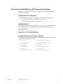
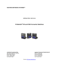
The following diagram illustrates the client / server architecture defined by the OPC
specification.
Client Application A
Client Application B
OPC Client
Interface
OPC Client
Interface
COM / DCOM
Mitutoyo
OPC Server
One or more
Serial Ports
The diagram shows that multiple OPC compliant client applications can communicate with an
OPC server simultaneously. Using DCOM, client and server software programs can be
configured to run on the same computer node or be distributed across a network of computers.
OPC servers provide a common view of automation information managed by the system for
which the server was written. The GagePort Mitutoyo OPC Server allows an OPC client to
read gage values from Mitutoyo gage hubs. Others examples include an OPC server for a PLC
providing access to PLC registers or an OPC server for a lab analyzer providing remote
monitoring (and control).
OPC clients use this common view of automation information in a variety of ways. This
includes providing human machine interfaces, historical data logging, and data mirroring
services. Users can write their own custom programs in languages such as Visual Basic or
Visual C++. Desktop programs can reference OPC server information. For example, users can
write VBA scripts in Microsoft Excel.
1-2
CIMPLICITY HMI GagePort Mitutoyo OPC Server–July 2001
GFK-2024
About the GagePort Mitutoyo OPC Server
The GagePort Mitutoyo OPC Server is as an out-of-process server compliant with the OPC
Data Access V2.0 specification. The OPC Server allows OPC clients to read and subscribe to
changes of GagePort Mitutoyo, FlexPort, and MIG2 gauge hub devices tied to the local serial
ports. It also supports many simple serial devices (such as bar code readers) tied directly to
the local serial ports..
The GagePort Mitutoyo OPC server is installed on the node that has the Mitutoyo devices
connected to its local serial ports.
It is recommended that the GagePort Mitutoyo OPC server be installed under Windows NT
4.0 in order to leverage all of the advantages of Microsoft COM/DCOM technology. Of
particular advantage are the DCOM security settings and the DCOM launch services available
only to NT4.0. These features make setup and maintenance of the OPC server easier.
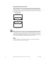
The following diagram illustrates the GagePort Mitutoyo OPC Server interacting with
physical devices through the node’s local serial ports. The OPC server must always run on the
same computer node where the physical devices are attached. However, the OPC client
application can be located on the same node or on another node visible through a network.
The ability to distribute OPC clients and servers across multiple platforms is one of the key
benefits of COM/DCOM technology.
Mitutoyo GagePort Devices
Serial Ports
Mitutoyo
GagePort
OPC Server
COM / DCOM
OPC Client
Application
GFK-2024
Introducing OPC Servers
1-3
Reviewing Notes about the GagePort Mitutoyo OPC Server
§
An OPC client attempts to connect to the GagePort Mitutoyo OPC Server. If the
OPC server process does not exist, COM/DCOM services attempt to activate it.
Upon successful activation of the OPC server, the OPC client begins interacting with
the OPC server to create server, group, and item objects. If the OPC server object is
already active, COM/DCOM returns a reference to the OPC server process. Only one
OPC server process can exist on a single computer node at a time.
§
When the last OPC client disconnects from the OPC server, the OPC server will
automatically terminate.
§
In the event that an OPC client does not disconnect gracefully, COM/DCOM
garbage collection algorithms will automatically clean the OPC client references
(this can take several minutes). Once the references are cleaned up, the OPC server
will terminate.
§
When the GagePort Mitutoyo OPC Server is activated by COM or DCOM, it runs as
a resident process that does not interact with the screen. When it is launched by the
user (by double clicking on the EXE or shortcut), it runs in interactive mode,
providing a User Interface on the screen.
§
The GagePort Mitutoyo OPC Server must be configured prior to being activated by
an OPC client. The server must first be run interactively, the serial ports configured,
and the configuration saved to disk (with File-Save As) so the server will know what
hardware is attached prior to being activated by an OPC client. During the File-Save
operation, the server will prompt the user (yes or no) whether to use this
configuration when activated by an OPC client. The user must answer Yes at least
once, so a valid configuration file is stored in the registry for use when the server is
started by an OPC client.
Reviewing GagePort Mitutoyo OPC Server Features
1-4
§
OPC Data Access V2.0 compliant, out-of-process server.
§
Browsing is supported for OPC clients that can browse hierarchically.
§
Extensive diagnostic tools for troubleshooting client / server connections.
§
Direct support for GagePort Mitutoyo, FlexPort, and MIG2 gage hubs with any
number of hub ports. The values read from these devices are delivered to the OPC
client as floating point (VT_R4) values.
§
Support for any simple serial device (such as bar code readers) with a variety of
message formats. In addition to CR, LF, and CRLF terminators, the OPC server can
be configured to handle messages with no terminator where the message length is
fixed and no terminator where the length is variable. Finally, a custom sequence of
characters can be defined to describe how the message terminates. This ‘Custom’
terminator can also be used to define characters at the end of the message that should
be ignored. Any number of characters at the beginning of the message can also be
ignored. The resulting value is sent to the OPC client as a VT_BSTR (String).
§
Serial port configuration is stored in native XML file format. The Doc/View model
provides traditional ‘File-New’, ‘File-Open’, ‘File-Save’, and ‘File-Save As’
functionality, so XML configuration files can be saved anywhere with any name.
When the user saves a configuration, they are prompted (YES or NO) whether to use
the saved file when the server is started by an OPC client.
CIMPLICITY HMI GagePort Mitutoyo OPC Server–July 2001
GFK-2024
Reviewing GagePort Mitutoyo OPC Server Specifications
Refer the OPC Foundation specification documents for more information about details
presented in this section.
OPC Specification Compliance
The GagePort Mitutoyo OPC Server is compliant with the following OPC standards:
§
Data Access Custom Interface Standard V2.0 and V1.0a.
§
Data Access Automation Interface Standard V2.0.
COM Program ID
Once installed, the GagePort Mitutoyo OPC Server is typically referenced by an OPC client
by its ProgID (program ID). The ProgID for the GagePort Mitutoyo OPC Server is:
GEF.GagePortServer
The OPC Server’s unique CLSID (class ID) is:
{BFBC14F0-1A51-11d5-9AD5-0050042953A6}
Supported Data Access Custom Interfaces
The CIMPLICITY HMI OPC Server implements the following COM interfaces. Note that
standard COM interfaces are not listed.
GFK-2024
§
IOPCServer
§
IOPCBrowseServerAddressSpace
§
IOPCItemProperties
§
IConnectionPointContainer
§
IOPCCommon
§
IOPCGroupStateMgt
§
IOPCASyncIO2
§
IOPCAsyncIO
§
IOPCItemMgt
§
IConnectionPointContainer
§
IOPCSyncIO
§
IDataObject
§
EnumOPCItemAttributes
§
IEnumOPCItemAttributes
Introducing OPC Servers
1-5
Supported Automation Interfaces
The GagePort Mitutoyo OPC Server relies on the standard automation wrapper supplied by
the OPC Foundation. The following diagram illustrates how the automation wrapper interacts
with the automation client (e.g. Visual Basic for Applications script) and the custom interface
of the GagePort Mitutoyo OPC Server. Note that the automation wrapper executes in process
with the automation client.
OPC Automation
Client Process
OPC Automation
Wrapper
COM / DCOM
OPC Custom
Interface
Mitutoyo Gage
Port Server Process
Note: Selection of the type of interface to use, custom or automation, depends on the goals of
the client application developer. Adhoc client applications written in Microsoft Visual Basic
(for example) typically use the automation interface. Automation interfaces are easy to use in
the VB (and VBA) development environments. However, the automation interface is slower
at execution time. Applications written in Microsoft Visual C++ (for example) use the custom
interface. This is the most efficient interface, but it is more complex to use.
Blobs
The GagePort Mitutoyo OPC Server does not support the use of blobs. Refer to the Data
Access specification for more information on blobs.
1-6
CIMPLICITY HMI GagePort Mitutoyo OPC Server–July 2001
GFK-2024
Reviewing GagePort Mitutoyo OPC Server Troubleshooting Tools
GagePort Mitutoyo OPC Server provides several diagnostic tools for troubleshooting
problems common to a heterogeneous software application environment. The tools are
designed to help a user diagnose specific aspects of a conversation between an OPC client and
the physical devices.
OPC Connection Trace Logging—OPC-related connection information is captured using
the Trace Logging diagnostic tool. This tool is used to log information about an OPC
conversation (between a client and a server) to a text file. See the section “OPC Connection
Trace Logging” in the "Using the GagePort MITUTOYO OPC Server Troubleshooting
Tools" chapter for more information.
Run-time Statistics—The OPC Server maintains run-time performance statistics for OPC
client-server interactions. These statistics can be used to diagnose computer node performance
problems and to tune an OPC client’s use of the GagePort Mitutoyo OPC Server resources.
See the section “GagePort Mitutoyo OPC Server Runtime Statistics” in the "Using the
GagePort MITUTOYO OPC Server Troubleshooting Tools" chapter for more information.
GFK-2024
Introducing OPC Servers
1-7
Using the GagePort Mitutoyo
OPC Server Naming Convention
About the GagePort Mitutoyo OPC Item Naming
Convention
OPC Client applications reference GagePort gage values using item IDs. Items IDs uniquely
reference a gage point value. Item IDs are constructed by using a client browse session or by
explicitly typing the Item ID string. This chapter defines the syntax of Item IDs supported by
the GagePort Mitutoyo OPC Server.
This OPC Server supports one unique syntax form. The form is always three levels deep and
separated by periods (.).
Note: The GagePort Mitutoyo OPC Server allows only one gage hub or simple device per
local serial port. Multi-drop serial configurations are not supported. This limitation is
expressed in the supported Item ID syntax.
GFK-2024
2-1
GagePort Mitutoyo Item ID Syntax
The Item ID syntax is as follows. Each field is described below.
PORTID.DEVICETYPE.PORTNUM
Field
Description
PORTID
The ID of the local serial port. e.g. COM1 or COM2.
DEVICETYPE
The type of device tied to the serial port. This can be one of three
values:
PORTNUM
Value
For a:
GPFP
GagePort or FlexPort gage hub.
MIG2
Mitutoyo MIG2 gage hub.
SIMPLE
Simple serial device.
The hub port where the gage is tied in. For GPFP and MIG2 device
types, this should be a value between ‘01’ and ‘xx’ where xx is the
number of ports configured for the hub.
For SIMPLE devices, this value must be VALUE.
GagePort Mitutoyo OPC Server Pre-Defined Item ID's
The GagePort Mitutoyo OPC Server has several pre-defined Item ID's used for referencing
server performance statistics. The Item ID for each statistic is listed below. An OPC client can
reference a statistic to monitor the performance of the OPC Server. Refer to the section
"Runtime Statistics" for more information on working with the statistics.
Note: Statistic Item IDs follow the same naming convention as a device point. The statistics
are assigned to a “fictitious” serial port called STATISTICS.
STATISTICS.CLIENTS.VALUE
Displays the number of OPC clients currently connected to the CIMPLICITY HMI OPC
Server.
STATISTICS.GROUPS.VALUE
Displays the number of OPC groups currently configured in the OPC Server.
STATISTICS.ITEMS.VALUE
Displays the number of OPC item references currently configured in the OPC Server. Note
that an item may appear in more than one group (or be referenced by more than one OPC
client). Each reference is counted in the statistic.
STATISTICS.READS.VALUE
Displays the number of synchronous and asynchronous read transactions performed by the
OPC Server in the last sample period. A read transaction is composed of one or more items.
2-2
CIMPLICITY HMI GagePort Mitutoyo OPC Server–July 2001
GFK-2024
STATISTICS.WRITES.VALUE
Displays the number of synchronous and asynchronous write transactions performed by the
OPC Server in the last sample period. A write transaction is composed of one or more items.
STATISTICS.EVENTS.VALUE
Displays the number of client subscription updates (i.e. unsolicited updates to an OPC client)
performed by the OPC Server in the last sample period. A single subscription update is
composed of one or more items.
STATISTICS.PERIOD.VALUE
The currently configured sample period for calculating reads/period, writes/period, and
subscriptions/period statistics.
GFK-2024
Using the GagePort Mitutoyo OPC Server Naming Convention
2-3
GagePort Mitutoyo OPC Server Data Types
The GagePort Mitutoyo OPC Server represents device point values in a canonical (or
baseline) format. This format, or data type, is compatible with Microsoft COM/DCOM
technology and is called a VARIANT data type.
As any Visual Basic programmer knows, a VARIANT can hold several types of data, usually
according to what is assigned to it or how it is used. The VARIANT data type is expressed by
a constant that begins with VT_.
Example
VT_I2 means the variant holds a two-byte signed integer.
VT_BOOL means it holds a boolean value, etc.
The GagePort Mitutoyo OPC Server always returns the following variant types:
For Devices
Variant Type always returned by GagePort Mitutoyo OPC
Server
GPFP
VT_R4.
This is a four-byte IEEE floating point value, sometimes called a
REAL value.
MIG2
VT_R4.
This is a four-byte IEEE floating point value, sometimes called a
REAL value.
SIMPLE device types
VT_BSTR variant type.
This is a String value.
Data Type Coercion
To ensure the highest throughput of point values through the GagePort Mitutoyo OPC Server
to an OPC Client, the client should always request the canonical data type of an attribute.
Example
The following table shows data types that should be requested based on the value source
with example variant types.
Client Requests
Values from a:
GPFP gage hub
MIG2 gage hub
SIMPLE serial device
Should request
the values as:
Four-byte REAL
Four-byte REAL
Strings
(Variant Type)
(VT_R4)
(VT_R4)
(VT_BSTR)
By requesting a point in canonical form, the OPC Server does not have to coerce (or convert)
between the data type stored internally and the data type requested by the OPC client.
The OPC Server provides coercion support for all non-array OPC items. The OPC Server
utilizes standard Microsoft coercion support routines. A drawback to relying on coercion is
the penalty of extra processing overhead required for each transaction. However, relying on
coercion in the OPC Server may simplify the OPC client or provide the user with the ability to
select the data type most applicable.
2-4
CIMPLICITY HMI GagePort Mitutoyo OPC Server–July 2001
GFK-2024
GagePort Mitutoyo OPC Server Timestamps
OPC Item Timestamp Applied
Either the time the value last changed or the value was refreshed is associated with each OPC
item value. This is known as the OPC item timestamp.
The GagePort Mitutoyo OPC Server synchronizes OPC item timestamps with the current
computer node time where the physical devices are attached.
OPC Item Timestamps Universal Time Format
The OPC Server returns all timestamps to an OPC client in universal coordinated time (UTC).
An OPC client must convert the timestamp to local time as required.
GagePort Mitutoyo OPC Server Item Quality
Associated with each OPC item value is an indicator of the quality of that value. This is
known as the OPC item quality. The quality of an item is based on whether or not the physical
device has provided a value for the Item ID or not.
The GagePort Mitutoyo OPC Server supports a subset of quality flags specified in the OPC
Foundation Data Access standard. The supported quality statuses and sub-statuses are listed
below.
GFK-2024
OPC Status
Good
OPC Sub-Status
N/A
Bad
N/A
Description
A value has been sent by the physical device
for the OPC item.
A value has not yet been received for the OPC
item. The value is unknown.
Using the GagePort Mitutoyo OPC Server Naming Convention
2-5
OPC Browse Interface Support
The GagePort Mitutoyo OPC Server supports hierarchical browsing of the items in the
server’s namespace . An example browse session follows. Note that the appearance and
behavior of a browse session is dependent upon how the OPC client is implemented. The
OPC server only provides the namespace information. The OPC client is responsible for
organizing and presenting the namespace.
2-6
CIMPLICITY HMI GagePort Mitutoyo OPC Server–July 2001
GFK-2024
Using the GagePort Mitutoyo
OPC Server User Interface
OPC Window Menu Options
The primary role of the GagePort Mitutoyo OPC Server is to interact with OPC clients
programmatically. Thus, no human user interface is required to satisfy the primary function of
the OPC Server. For this reason, when the server is launched by an OPC client, it runs
invisibly as a resident process.
However, the OPC Server does have a simple user interface (when run interactively) that is
used for setting up the OPC Server for an installation and for accessing some of the
troubleshooting tools provided by the OPC Server.
The user interface provides the following features.
GFK-2024
§
Configuration of the devices tied to the serial ports and the saving and opening of the
XML files that hold these settings.
§
Configuration of the ‘Startup File’. This is the XML configuration file used when the
server is started by an OPC client.
§
Trace logging diagnostic tool configuration.
3-1
The OPC Server’s client window of the user interface consists of a traditional Windows List
View with three columns.
Column 1
Shows all of the OPC Items the server has in its namespace according
to the current serial port configuration. Note that the first seven items
are the internal OPC server statistics. These are always present and
available to any OPC client that chooses to reference them.
Column 2
Shows the current (more accurately, the last known) value of the item.
If no value has been received from the hardware, the value shows “Bad
Quality”.
Column 3
Provides a description of the item.
Above the List View, the user interface provides a toolbar for the more popular menu options.
Finally, there are the menu options.
§
File menu
§
Edit menu.
§
Trace menu.
Selections for each menu option are described below.
File Menu–in OPC Server Window
The OPC Server window File menu has the following selections:
New
This option ‘Clears’ the current serial port configuration and closes the current configuration
file if one is loaded. The title bar will reflect an ‘Untitled’ configuration. Note that a ‘default’
configuration is loaded on File – New; this is not an empty configuration. The default
configuration defines a ‘Simple’ serial device on COM1. This explains the last item in the
screen shot above.
Open…
This option provides a traditional File-Open dialog box. Note that the GagePort Mitutoyo
OPC Server uses XML files as its native configuration file type. With this option, you can
open a serial port configuration file, which was previously defined and saved.
Save
This option saves the current serial port configuration file to disk. If no configuration file is
currently loaded, this option acts the same as the Save-As option.
Save As…
This option provides a traditional File-Save As dialog box. Navigate to the folder where you
wish to store the configuration file, then enter a name for the file. There is no need to enter the
file’s extension. An .xml extension will be appended to the name you enter.
3-2
CIMPLICITY HMI GagePort Mitutoyo OPC Server–July 2001
GFK-2024
Both the Save and Save As options prompt to ask if the configuration being saved should be
the configuration loaded when the OPC server is launched by an OPC client…
It is very important that ‘Yes’ is selected at least once before the server is launched by an
OPC client. Selecting ‘Yes’ causes the OPC server to store the path to this file in the registry.
The server then uses this configuration file when it is launched by an OPC client. If no
‘Startup File’ has been stored in the registry, then the default configuration will be used. This
is most likely not the desired result.
MRU
The ‘Most Recently Used’ files appear next on the ‘File’ menu. This is a short list of
configuration files that have most recently been opened.
Exit
Terminates the GagePort Mitutoyo OPC Server. If configuration has been modified, but not
saved, the user is notified and given the option to save the configuration.
Edit Menu–in OPC Server Window
The OPC Server window Edit menu has the following selections:
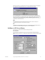
Port Properties
Select this option to configure the devices tied to the serial ports of the node where the
GagePort Mitutoyo OPC Server is running. This option opens the COM Port Properties dialog
box.
GFK-2024
Using the GagePort Mitutoyo OPC Server User Interface
3-3
Number of COM Ports…Select the number of serial ports that will be configured. This
directly affects the number of items in the ‘Showing Properties for
Port’ combo box. If this value is lowered, a warning is displayed
that configuration will be lost for the ports being removed. This
value can not be less than one. At least one serial port must be
configured.
Showing Properties…
Select the serial port to be configured.
Port Settings, Device Settings and Message Terminator controls
will update to reflect the configuration of the selected serial port.
This is a navigation tool for the dialog box, not an actual stored
property.
Port Settings
Device Settings
These are the standard serial port configuration options:
Baud Rate
The Baud Rate for communication with the
device.
Parity
The Parity for communication with the device.
Data Bits
The Data Bits for communication with the
device.
Stop Bits
The Stop Bits for communication with the
device.
The type of device tied to the serial port:
No Device
Use this option if there is no device tied to this
serial port. For example, if four ports are being
configured (COM 1 through COM 4), but there
is no device on COM 3, use this option to
indicate this.
GPFP Hub
Use this option to indicate there is a GagePort or
a FlexPort hub tied to this serial port. Use the
spinner control to select the number of ports on
the hub.
MIG2 Hub
Use this option to indicate there is a Mitutoyo
MIG2 hub tied to this serial port. Use the spinner
control to select the number of ports on the hub.
Simple Serial Device
Use this option to indicate there is a
Simple serial device tied to this serial port (such
as a bar code reader). The OPC server assumes
this device will send ASCII strings to the serial
port in an unsolicited manner. The value is
delivered to the OPC client as a string
(VT_BSTR) type.
Message Terminator
3-4
Define the structure of the data being received by the OPC server.
CR Only
This option indicates the message sent by the
device ends with a Carriage Return character
(ASCII 13).
LF Only
This option indicates the message sent by the
device ends with a Line Feed character (ASCII
10).
CRLF
This option indicates the message sent by the
device ends with a Carriage Return character
(ASCII 13) followed by a Line Feed character
(ASCII 10).
CIMPLICITY HMI GagePort Mitutoyo OPC Server–July 2001
GFK-2024
None (fixed Length)
This option indicates that the message
has no terminating character(s)… and therefore,
must be fixed length. Use the spinner to indicate
the number of characters that make up the
message.
Note: There is a special case use of this option
for simple devices that send variable length, not
terminated messages. If the number of characters
is set to 0, this special case will take effect. In
this case, the OPC server will make use of the
serial port Timeout value by using the first
timeout, after a series of characters, to indicate
the end of the message. This is very useful for
bar code readers that do not terminate the
messages they send, but may be used to read
codes of varying lengths!
Custom
This option indicates that a custom message
terminator will be defined. Enter a commadelimited list of ASCII values that define how
the message terminates. For example, entering
13, 10 would be the same as using the CRLF
terminator. NOTE: This type of terminator can
be used to strip extra characters from the
message. Since the custom terminator is stripped
from the message before it is sent to the OPC
client, you can specify trailing characters in the
message that you want stripped off.
Ignore First xxx This option allows any number of prefixed
characters to be stripped from the message
before it is sent to the OPC client.
OK
Save the serial port settings to the document, and close the COM
Port Properties dialog box. NOTE:
Important: This does not save the document to disk! Be sure to
use the File-Save or File-Save As menu options to permanently
save any changes to an .xml configuration file.
Cancel
Close to the COM Port Properties Dialog without saving the
changes.
ü Server is Running
Server is Running is a checked (toggle) type menu option. When the GagePort Mitutoyo OPC
Server is launched by an OPC client, it runs hidden from view, and the serial port monitors
are automatically started. When the OPC server is run interactively, the serial port monitors
are not automatically started. By selecting this menu option, a check mark appears next to it,
and the serial port monitors are started. As gage devices send data to the serial ports, the
Value column in the List View will be updated to reflect these new values. Selecting this
menu option a second time will stop the serial port monitors.
Note: Configuration changes made while the serial port monitors are running will not be
honored until the server is stopped and then started again.
GFK-2024
Using the GagePort Mitutoyo OPC Server User Interface
3-5
Trace Menu–in OPC Server Window
The OPC Server window Trace menu has the following selections:
Off
Select this option to disable OPC connection trace logging. The trace log file is closed.
Connect
Select this option to enable OPC connection trace logging and to set the level of tracing to
capture server activation events and client connect / disconnect events.
Group
Select this option to enable OPC connection trace logging and to set the level of tracing to
capture OPC group creation, deletion, and modification events.
Item
Select this option to enable OPC connection trace logging and to set the level of tracing to
capture OPC item transaction events (read, write, subscription updates).
All
Select this option to enable OPC connection trace logging and to set the level of tracing to
capture all Connect, Group, and Item transaction events.
Set Trace File…
Select this option to specify the filename used for logging OPC client / server conversation
information. While trace logging is on, all client / server conversation information is
appended to this file. Trace logging is enabled by selecting one of the trace levels from the
Trace menu option (Connect, Group, Item, All).
View Menu–in OPC Server Window
The OPC Server window Trace menu has the following selection:
Toolbar / Status Bar
These menu items toggle the visibility of the toolbar and status bar, allowing a couple more
rows of the list view to be seen.
Help Menu–in OPC Server Window
The OPC Server window Help menu has the following selection:
About GEFGagePortServer…
About GEFGagePortServer… displays the proverbial About dialog box.
3-6
CIMPLICITY HMI GagePort Mitutoyo OPC Server–July 2001
GFK-2024
Using the GagePort Mitutoyo
OPC Server Troubleshooting
Tools
About the GagePort Mitutoyo OPC Server
Troubleshooting Tools
The GagePort Mitutoyo OPC Server provides troubleshooting tools to help a user
diagnose specific aspects of a conversation between an OPC client and a gage tied to the
serial port. There are three tools provided with the OPC server. Uses of the tool outputs
are discussed in this section.
GFK-2024
The Value column of the List View
When things are not right, this is the first place
to check. By running the server interactively,
then ‘Starting’ it, you can test communication
with the gage hubs without having to connect
with an OPC client. This way you can verify that
the OPC server is communicating successfully
with the gages.
OPC Connection Trace Logging
OPC-related connection information is captured
using the Trace Logging diagnostic tool. This
tool is used to log information about an OPC
conversation (between a client and a server) to a
text file. See the next section for more details.
Run-time Statistics
The OPC Server maintains OPC conversation
run-time performance statistics. These statistics
can be used to diagnose computer node
performance problems and to tune OPC client
reporting requirements. See page 4 - 5 for more
information.
4-1
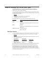
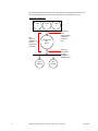
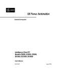
The following diagram illustrates the scope of diagnostic information generated by each
tool. The following sections describe the output from each tool and how to use it.
Gage Hubs / Serial Ports
COM
1
Use
Runtime
Statistics to
monitor
through put
problems.
COM
2
COM
3
Use the List
View
Values column
to diagnose
problems
here.
MITUTOYO
OPC
Server
Use OPC
Connection
Logging
to diagnose
problems here.
OPC
Client A
4-2
OPC
Client B
CIMPLICITY HMI GagePort Mitutoyo OPC Server–July 2001
GFK-2024
OPC Connection Trace Logging
Trace logging monitors the state of a connection between an OPC client(s) and the
GagePort Mitutoyo OPC Server. The details tracked are determined by the chosen trace
level as follows.
Trace Level
Description
Connect
Log server activation events and client connect / disconnect events.
Group
Log OPC group creation, deletion, and modification events.
Item
Log OPC item transaction events (read, write, subscription updates).
All
Log all events.
The OPC server must be configured to run interactively in order to access trace logging
menu options.
Note: Messages written to the trace log assume that the user is familiar with the OPC
Foundation Data Access specification.
Interpreting the Trace Log
The trace log is composed of a series of messages. Each message logs a single OPC
client-server event. A message is prefaced with a local machine date and time stamps and
the source of the trace message.
Note: The date/time and source are not shown in the following sample trace log for the
purposes of clarity.
The sample trace log illustrates the sequence of messages logged with the trace level set
to All. The OPC client initiated the following sequence of events (note that the OPC
client used to generate the log is Data Access 1.0A compliant).
GFK-2024
1.
The OPC client connected to the GagePort Mitutoyo OPC Server.
2.
The client created an OPC group and called it Group1. The client created two
advise sinks for Group1 for:
§
Receiving subscription notification callbacks (i.e. unsolicited updates from
server for all items in Group1).
§
Receiving asynchronous write complete callbacks (i.e. notification from the
OPC Server when an asynchronous write operation completed).
3.
The client creates a second OPC group called Group2 with the similar advise
sinks as Group1.
4.
The client added an OPC item to Group1 called COM1.SIMPLE.VALUE.
5.
Immediately the OPC Server began reporting to the client data change
notifications (via a callback into the client).
6.
The client proceeded to add two more points: COM2.GPFP.01 and
COM2.GPFP.02.
7.
Note that immediately after each new item was added, the number of items
reported in the callback to the client increased. This is because the values are
changing in the gages and being reported to the client at the requested OPC
group update rate.
Using the GagePort Mitutoyo OPC Server Troubleshooting Tools
4-3
8.
The client then removed the OPC group Group2. Prior to doing this, it
disconnects the advise sinks previously setup.
9.
The client then deletes the OPC group Group1. First it removes the item
references from the group and then it disconnects the advise sinks.
10. Finally, the client disconnects from the OPC Server.
OPC Client connected
Added OPC Group 'Group1'
Group 'Group1': client connected OPCSTMFORMATDATATIME V1.0 advise sink
Group 'Group1': client connected OPCSTMFORMATWRITECOMPLETE V1.0 advise sink
Added OPC Group 'Group2'
Group 'Group2': client connected OPCSTMFORMATDATATIME V1.0 advise sink
Group 'Group2': client connected OPCSTMFORMATWRITECOMPLETE V1.0 advise sink
Group 'Group1': added item 'COM1.SIMPLE.VALUE' (handle=18155968)
Group 'Group1': Invoked V1.0 data change callback (with timestamps) for 1 item(s)
Group 'Group1': Invoked V1.0 data change callback (with timestamps) for 1 item(s)
Group 'Group1': added item 'COM2.GPFP.01' (handle=18157088)
Group 'Group1': Invoked V1.0 data change callback (with timestamps) for 2 item(s)
Group 'Group1': Invoked V1.0 data change callback (with timestamps) for 2 item(s)
Group 'Group1': added item 'COM2.GPFP.02' (handle=18158672)
Group 'Group1': Invoked V1.0 data change callback (with timestamps) for 3 item(s)
Group 'Group1': Invoked V1.0 data change callback (with timestamps) for 3 item(s)
Group 'Group2': client disconnected V1.0 OPCSTMFORMATDATATIME advise sink
Group 'Group2': client disconnected V1.0 OPCSTMFORMATWRITECOMPLETE advise sink
Removed OPC Group 'Group2'
Group 'Group1': Invoked V1.0 data change callback (with timestamps) for 3 item(s)
Group 'Group1': Invoked V1.0 data change callback (with timestamps) for 3 item(s)
Group 'Group1': removed item 'COM1.SIMPLE.VALUE' (handle=18155968)
Group 'Group1': removed item 'COM2.GPFP.01' (handle=18157088)
Group 'Group1': removed item 'COM2.GPFP.02' (handle=18158672)
Group 'Group1': client disconnected V1.0 OPCSTMFORMATDATATIME advise sink
Group 'Group1': client disconnected V1.0 OPCSTMFORMATWRITECOMPLETE advise sink
Removed OPC Group 'Group1'
OPC Client disconnected
Using the Trace Log
Following is a sample list of problems that can be diagnosed with the trace log. The list is
not exhaustive. It is intended as a guide only.
4-4
§
Client connection problems. Use the log to verify if the OPC Server received the
client’s request to connect. This request may have been blocked by DCOM
security.
§
DCOM security authorization problems. This can occur if a client can connect to
the OPC Server but cannot access server objects. For example, the client can
connect to the OPC Server but cannot create an OPC group.
§
Validate the OPC items requested by a client and verify the item ID syntax.
§
View the sequence of OPC interface requests to verify the correct operation of a
client.
§
Verify that a client gracefully disconnects.
§
Troubleshoot subscription problems (i.e. callbacks into the client by the OPC
Server when data changes are reported). In this case, the client is able to perform
synchronous and asynchronous read and write requests but cannot receive
subscription updates. This may be due to a DCOM security authentication
problem on the client machine. The client is unable to authenticate the OPC
server.
§
See how a client organizes OPC groups and OPC items within groups.
CIMPLICITY HMI GagePort Mitutoyo OPC Server–July 2001
GFK-2024
GagePort Mitutoyo OPC Server Runtime Statistics
The GagePort Mitutoyo OPC Server maintains runtime statistics to diagnose and correct
performance problems. Typically, performance problems are caused by how an OPC
client application organizes and uses the resources supplied (e.g. group objects and item
objects) by an OPC server.
The OPC Server maintains statistics about OPC client-server interactions. These statistics
are viewable from an OPC client by reading pre-defined item IDs from GagePort
Mitutoyo OPC Server. See the section “Server Statistic OPC Items” in the GagePort
Mitutoyo OPC Server Information chapter for a list of the item IDs.
Following are the statistics that are maintained about the OPC Client.
Client Connections
The number of OPC clients currently connected to the GagePort Mitutoyo OPC Server.
Client Groups
The number of OPC groups (for all clients) currently configured in the OPC Server.
Client Items
The number of OPC item references (for all groups) currently configured in the OPC
Server. The same item may appear in more than one group (or be referenced by more
than one OPC client). Each reference is counted in this statistic.
Read Transactions Per Period
The number of synchronous and asynchronous read transactions performed by the OPC
Server in the last sample period. A read transaction is composed of one or more items and
may be a cache read or device read.
Write Transactions Per Period
The number of synchronous and asynchronous write transactions performed by the OPC
Server in the last sample period. A write transaction is composed of one or more items.
Subscription Transactions Per Period
The number of client subscription updates (i.e. unsolicited updates to an OPC client)
performed by the OPC Server in the last sample period. A single subscription update is
composed of one or more items.
GFK-2024
Using the GagePort Mitutoyo OPC Server Troubleshooting Tools
4-5
Using the Runtime Statistics
The runtime statistics can provide an initial indication of client-server interaction
problems. Use the statistics to identify the general problem and then use the OPC
Connection Trace Logging to identify the specific problem.
Client Groups and Client Items
Client groups and Client items provide a rudimentary indication of how an OPC client
organizes the group and item object resources supplied by the GagePort Mitutoyo OPC
Server. Some OPC client applications initially create a large number of OPC groups and
disable the subscription updates until needed. While this will not cause CPU loading
problems, it could cause the initial connection and setup time with the GagePort Mitutoyo
OPC Server to be slow or for a large amount of memory to be used by the OPC Server.
Reads Transactions Per Period, Write Transactions Per Period
Reads transactions per period and write transactions per period provide information on
the OPC Server loading. For example, a high Read Transactions Per Period or Write
Transactions Per Period value may coincide with abnormally high CPU loading. The
client may be continuously performing a large number of device read or device write
requests. (Note that cache reads are very efficient and do not typically cause significant
CPU loading problems.)
Subscriptions
Subscriptions updates (e.g. unsolicited updates of changed values and/or quality
information by an OPC server to an OPC client) may cause high CPU loading when the
OPC client requested OPC group update rates are small for groups with rapidly changing
values. If subscription updates are not occurring when OPC items are known to be
changing, then there may be a DCOM security authentication problem on the computer
hosting the OPC client application. The security on this node may not be configured to
allow the GagePort Mitutoyo OPC Server to post subscription updates (via callbacks).
4-6
CIMPLICITY HMI GagePort Mitutoyo OPC Server–July 2001
GFK-2024
Configuring the GagePort
Mitutoyo OPC Server DCOM
About DCOM Security
The GagePort Mitutoyo OPC Server is implemented as a Microsoft COM (Component
Object Model) object. DCOM (Distributed COM) provides the framework and the
services required to deploy COM objects in a distributed environment. One of these
services is security. DCOM security leverages the underlying Windows operating system
security services. Those familiar with Windows (NT/98/2000) security issues will find
that there are a few security issues unique to the distributed environment.
To better understand the security issues that can affect a connection between an OPC
client and the GagePort Mitutoyo OPC Server, this chapter provides an overview of
DCOM related security. The topic of DCOM security (and Windows security for that
matter) is extensive and can be confusing. There are several books dedicated to these
topics alone. What is presented here is a synopsis of the issues that affect OPC client /
server interactions.
DCOM security topics can be broken down into four areas (for definition purposes):
§
Authentication,
§
Authorization,
§
Activation and
§
Launch identity.
Note: Activation security is unique to DCOM.
Authentication–DCOM Security
Authentication security ensures that the interaction between an OPC client and the
GagePort Mitutoyo OPC Server is legitimate. Authentication security for DCOM is an
extension of the standard Windows operating system security (which itself is layered
upon secured RPC (remote procedure call)). Authentication poses the question “Is the
OPC client who it says it is?” and “Is the OPC server who it says it is?” The user
configures the level of authentication required which specifies how often this question is
posed. Each more secure level places extra processing overhead on communications
GFK-2024
5-1
between the OPC client and the OPC server. A client and server negotiate to the highest
level of authentication when the configured authentication levels differ.
For example, authentication can be required only at OPC client connection time to a
server (level = connect). Once a client is connected (and is authorized to use the OPC
Server), all interactions are performed without further authentication. As another
example, authentication can be required at the packet level (level = Packet Privacy), with
each packet being fully encrypted. The choice of the authentication level is dependent on
the security policies of the user.
In a multi-node computing environment the security system on the computer node
running the OPC server must be able to verify that the security ID of the OPC client is
valid. In a domain environment, domain accounts must be validated. In peer-to-peer
environments, matching local user accounts must be configured.
Authentication of an OPC client must be satisfied before authorization and activation
permissions are checked. If a client cannot be authenticated, permission checking for the
requested action is not performed.
Authorization–DCOM Security
Once an OPC client transaction has been authenticated, DCOM security must determine
if that OPC client is authorized to perform call-level interactions with the OPC server.
(COM/DCOM technology allows OPC client applications to make programmatic calls
across process and computer node boundaries.) This determination is made by looking at
the ACL (access control list) for the OPC server COM object. This ACL (or list of users
and/ or user groups) for the OPC server is configured using the DCOMCNFG utility
supplied with the Windows operation system. See the section "Tools for Configuring
DCOM Security" in this chapter for more information about DCOMCNFG.
If the OPC client’s user identity is listed on the OPC server’s access permissions ACL (as
a user or group member), then the OPC client can access GagePort Mitutoyo OPC Server
objects.
Activation–DCOM Security
Activation security is unique to DCOM. The DCOM framework provides the ability for
an OPC client to access the GagePort Mitutoyo OPC Server object. If the OPC server
object is installed on another computer node, then the framework launches (or activates)
the OPC server (if it already not running) on behalf of the client. Activation permission
checking works the same as authorization permission checking. An authenticated client’s
user identity is checked against the OPC server’s ACL for launch permissions. Activation
permissions for the GagePort Mitutoyo OPC Server are setup using DCOMCNFG.
Note: Activation services are not supported by Windows NT/98/2000 DCOM. Users
must manually launch the GagePort Mitutoyo Server on these operating system
platforms.
Launch Identity–DCOM Security
Most often, the GagePort Mitutoyo OPC Server is configured to run as a background
process (i.e. non-interactive mode) with the OPC Server starting and stopping as OPC
clients connect and disconnect. The OPC server must be given a user identity under
which to run (i.e. administrator account, the current interactive user, or a special account
setup for the OPC server). The launch identity for the GagePort Mitutoyo OPC Server is
specified using the DCOMCNFG utility.
5-2
CIMPLICITY HMI GagePort Mitutoyo OPC Server–July 2001
GFK-2024
Tools for Configuring DCOM Security
Note: It is assumed that reader can configure user accounts (either on a local machine or
in a domain environment) and assign group memberships for the user accounts.
Steps to configure DCOM security include:
Step 1.
Configure DCOMCNFG.
Step 2.
Do minimal DCOM configuration for client connections.
Step 1. Configure DCOMCNFG
The GagePort Mitutoyo OPC Server relies on the DCOMCNFG (commonly referred to
as dee-com config) utility supplied with the Windows operating system. The OPC
server does not programmatically initialize DCOM security.
The following tasks provide an overview of frequently used DCOM settings. However,
the settings you choose depend on your network configuration needs and required level
of security.
Task 1.
Open the Distributed COM Configuration Properties dialog box
Task 2.
Double-check default DCOM settings
Task 3.
Set important DCOMCNFG settings for the GEF GagePort OPC Server
Task 4.
Set important DCOMCNFG settings for an OPC client.
Step 1. Configure DCOMCNFG
Task 1. Open the Distributed COM Configuration Properties
Dialog Box
Task 1. Open the Distributed COM Configuration Properties dialog box:
Option 1–from an MS_DOS window
1.
Open an MS_DOS window.
2.
Type dcomcnfg at the prompt.
Option 2–from Windows Start menu
1.
Click Start on the Windows task bar.
2.
Select Run on the Start menu.
The Run dialog box opens.
3.
Type dcomcnfg in the Open field.
Result: The Distributed COM Configuration Properties dialog box opens.
GFK-2024
Configuring the GagePort Mitutoyo OPC Server DCOM
5-3
The utility is composed of multiple dialog boxes, selectable by tabs across the top as
shown below. The user interface varies slightly among Windows NT versions. Therefore,
the user interface for your version of Windows NT may be slightly different. However,
the option descriptions in this section are the same for the service pack releases.
Note: COM objects that programmatically initialize DCOM security will cause the
DCOMCNFG settings to be ignored.
5-4
CIMPLICITY HMI GagePort Mitutoyo OPC Server–July 2001
GFK-2024
Step 1. Configure DCOMCNFG
Task 2. Double-check Default DCOM Settings
The current default DCOM settings may be appropriate for the GEF GagePort OPC
Server addition. The most important settings to double-check using the tabs in the
Distributed COM Configuration Properties dialog box are as follows.
Tab
Select
DCOMCNFG Default Properties
Enable Distributed COM on this computer.
Set the Default Authentication Level to satisfy
the network security requirements of the
installation.
(Windows NT 4.0 SP4 allows the Authentication
Level to be customized for the OPC Server. The
DCOMCNFG SP3 utility provides this feature at
the default level only.)
Set the Default Impersonation Level to
Identify.
Graphic displays
default settings.
GFK-2024
Configuring the GagePort Mitutoyo OPC Server DCOM
5-5
DCOMCNFG Default Security
5-6
If customized access permissions and launch
permissions were not specified on the Security
tab in the GEF GagePort OPC Server Properties
dialog box (See page 5-8), DCOM security for
the OPC -Server uses the user and/or group
settings (ACL) assigned under Default Access
Permissions and Default Launch
Permissions.
CIMPLICITY HMI GagePort Mitutoyo OPC Server–July 2001
GFK-2024
Step 1. Configure DCOMCNFG
Task 3. Set Important DCOMCNFG Settings for the GEF
GagePort OPC Server
This section lists the DCOMCNFG settings that are relevant for configuring the DCOM
security for the GagePort Mitutoyo OPC Server.
The OPC Server can be configured to use default security settings for the computer node
or the settings can be customized to adhere to your network's requirements.
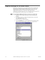
Task 3. Set important DCOMCNFG settings for the GEF GagePort OPC
server.
1.
Double-click GEF GagePort OPC Server in the Distributed COM Configuration
Properties dialog box on the Applications tab.
The GEF GagePort OPC Server Properties dialog box opens.
Graphic displays
default settings.
GFK-2024
Configuring the GagePort Mitutoyo OPC Server DCOM
5-7
2.
Configure the tabs to your network's needs. The following descriptions show
frequently used specifications.
Tab
Most Frequently Used Selections
Location
The option:
Run application on this computer.
Graphic displays
default settings.
Security
Use default access permissions (for authorization security)
and
Use default launch permissions (for activation security)
unless the default settings do not satisfy your system security
requirements.
If customized settings are required, specify the trusted users
and/or groups (ACL) for authorization and activation security
settings.
Graphic displays
default settings.
5-8
CIMPLICITY HMI GagePort Mitutoyo OPC Server–July 2001
GFK-2024
Identity
Options provide the following benefits (and limitations).
The interactive User
Benefit: Allows other interactive clients to attach to the
server.
Limitation: The server will shut down after a log out and data
collection will be stopped. However, CIMPLICITY may still
be running.
The launching User
Benefit: Server continues to run after log out; data continues
being collected.
Limitation: Other interactive clients cannot attach to the
server.
This user
Benefit: Allows other interactive clients to attach to the server
and continues to run after log out; data collection continues.
Limitation: Requires more configuration than the other two
options.
Recommendation
When initially setting up the OPC server or troubleshooting
client/server interaction problems, specify The interactive
user.
Otherwise, specify This user and supply a valid user account
(local machine or domain as required) and the passwords
configured for this user account.
Important: The OPC server will take on the identity (and
privileges and permissions) of the user account when activated
by an OPC client. The chosen user account (either interactive
or this user) must be authenticated on a remote OPC client
node in order for some OPC interactions to occur (e.g.
subscription notifications).
1
2
3
1 Allows other interactive
clients to attach to the
server.
2 Continues to run after
logout.
3 Does both of the above.
GFK-2024
Configuring the GagePort Mitutoyo OPC Server DCOM
5-9
Endpoints
The default setting is default system protocols.
Graphic displays
default settings.
Step 1. Configure DCOMCNFG
Task 4. Set Important DCOMCNFG Settings for an OPC Client
If the OPC client application is a COM object and does not initialize DCOM security
programmatically, then the DCOMCNFG utility must be used to specify the Access
Permissions and the Authentication Level. This is required for authenticating callbacks
into the client by the OPC server. DCOM Security on the OPC client computer node must
not only authenticate the user identify of the OPC server but also must determine if the
OPC Server is allowed to make calls on client owned objects. Callbacks are invoked by
the OPC server to provide subscription updates and completion notifications for
asynchronous read and write operations.
If the OPC client application is not a COM object (i.e. the OPC client application is not
listed in DCOMCNFG), then the DCOM security settings for Default Access
Permissions and Default Authentication Level are applied.
5-10
CIMPLICITY HMI GagePort Mitutoyo OPC Server–July 2001
GFK-2024
Step 2. Do Minimal DCOM Configuration for Client Connections
The instructions in this section outline how to setup the GagePort Mitutoyo OPC Server
and the OPC client DCOM security settings to get up and running quickly. Effectively,
the settings outlined here turn off all security authentication. If authentication is disabled,
then by default all permission checking (for authorization and activation security) is
disabled. Any OPC client application can use GagePort Mitutoyo OPC Server objects and
the OPC server can call back into the OPC client application.
Guidelines: For DCOM Configuration
This section presents general guidelines for “tightening” DCOM security settings for
GagePort Mitutoyo OPC Server / OPC client interactions. This list of guidelines is not
exhaustive. It is assumed the reader is familiar with Window security issues and DCOM
security in particular. The issue of security in an automation environment is currently
being addressed by an OPC Foundation working committee.
Note: Whenever possible, try to use DCOMCNFG settings that are custom to the GagePort
Mitutoyo OPC Server. This has two benefits; one, as the OPC server is setup for initial
use, the behavior of other COM objects installed on the same computer node is not
affected and two, future changes to other COM object DCOM security settings do not
affect the behavior of a correctly operating GagePort Mitutoyo OPC server.
§
Enable authentication security by setting the DCOMCNFG
Default Authentication Level at a level of at least Connect. If you are running
DCOMCNFG supplied with SP4, then ensure that the “Authentication Level”
custom setting is set to at least the level Connect. Once authentication is
enabled, DCOM security will attempt to verify the user identities of both the
OPC server and the OPC client. Thus, user accounts must be setup correctly if
the OPC Server is on one computer node and the client is on another computer
node. See the guideline below on domain authentication setup. In a peer-to-peer
network, the user account under which the OPC server is running must also exist
on the OPC client machine, and vice versa.
§
Enable GagePort Mitutoyo OPC Server activation security by specifying known
users and / or groups in the DCOMCNFG “Use custom launch permissions”
option for the OPC Server. As a rule, the activation security should always be
more restricted than the authorization security. This prevents the situation where
an OPC client can activate the GagePort Mitutoyo OPC Server, but cannot use
the OPC Server objects.
§
To restrict access of OPC clients to a GagePort Mitutoyo OPC Server that is
already running (authorization security), modify the access control list (ACL) of
the OPC server by editing the “Use custom access permissions” option of
DCOMCNFG.
§
A domain authentication architecture provides the lowest cost solution (from a
maintenance perspective) for DCOM security. If you are using a domain, then
follow these general setup guidelines:
1. Create a new domain group. Users part of this group will be allowed to
launch the GagePort Mitutoyo OPC Server and access it’s objects.
2. Add the new group to the launch permissions and access permissions ACL
for the GagePort Mitutoyo OPC Server. Do this using DCOMCNFG.
3.
GFK-2024
Make all user accounts that run an OPC client application part of this new
group.
Configuring the GagePort Mitutoyo OPC Server DCOM
5-11
Registry Settings for Off-node Clients
Remote OPC client applications (i.e. client applications that run on a computer node
other than the one running the GagePort Mitutoyo OPC Server) do not have to have
GagePort Mitutoyo software installed on a remote machine in order to access the
GagePort Mitutoyo OPC Server. A remote OPC client registry entry file
(CIMOpcServer.reg) ships with the OPC server. The registry entries in this file allow an
OPC client application to reference the OPC server on another node.
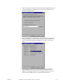
To setup GagePort Mitutoyo OPC Server access from a remote node:
5-12
1.
Log onto the remote computer node using an account with administrator
privileges.
2.
Using Window explorer (or a similar file navigation utility), access the file
named GEFGagePortServer.reg.
3.
Double-click the file to update the registry.
4.
Using the DCOMCNFG utility, select the Applications tab and double click the
application labeled GagePort Mitutoyo OPC Server (see graphic below).
CIMPLICITY HMI GagePort Mitutoyo OPC Server–July 2001
GFK-2024
GFK-2024
5.
Select the Location tab. Type the node name where the GagePort Mitutoyo OPC
server is installed. In the example below, the OPC Server is installed on the
MANUFACTURING node.
6.
Select the General tab. An example of this sheet is shown below. It shows that
the GagePort Mitutoyo OPC Server object is registered on this machine, but
points to another node (MANUFACTURING) for activation / access of the
object.
7.
A client application on the remote node should now be able to reference the
GagePort Mitutoyo Server (given that DCOM security issues have been
addressed). The ProgID of the OPC Server is GagePort Mitutoyo OPC Server
and the CLSID is {BFBC14F0-1A51-11d5-9AD5-0050042953A6}.
Configuring the GagePort Mitutoyo OPC Server DCOM
5-13
Index
Blobs
And GagePort Mitutoyo OPC Server 1-6
Browser
OPC interface support 2-6
COM Port Properties Dialog Box
Device Settings 3-4
Fields 3-3
Message Terminator 3-4
Number of COM Ports 3-4
Port Settings 3-4
Showing Properties 3-4
COM Program ID 1-5
COM/DCOM
And OPC standard 1-1
Benefits with GagePort Mitutoyo OPC Server 1-3
GagePort Mitutoyo OPC notes 1-4
Configuration
When for GagePort Mitutoyo OPC notes 1-4
Connect 3-6
OPC Server trace logging 4-3
Connection
GagePort Mitutoyo OPC notes 1-4
Convention
Naming OPC item 2-1
Convert
Mitutoyo OPC Server data type 2-4
Custom Programs
OPC client/server architecture 1-2
C
D
Client Connections
OPC client statistics 4-5
Client Groups
OPC client statistics 4-5
Client Groups and Client Items
OPC runtime statistics 4-6
Client Items
OPC client statistics 4-5
Clients
Registry settings for off-node 5-12
Coercion
Data type 2-4
Columns
In OPC Server window 3-2
Data Access
OPC standard 1-1
Supported custom interfaces 1-5
Data Access Automation Interface Standard 1-5
Data Access Custom Interface Standard 1-5
Data Types
Coercion 2-4
Convert 2-4
For simple devices 2-4
GagePort Mitutoyo OPC Server 2-4
VARIANT 2-4
A
About GEFGagePortServer… 3-6
Activation
DCOM Security 5-2
Alarm Handling
OPC standard 1-1
All 3-6
OPC Server trace logging 4-3
Architecture
OPC specification 1-2
Authentication
DCOM Security 5-2
Authorization
DCOM Security 5-2
Automation
Supported interfaces 1-6
B
GFK-2024
Index
Index-i
DCOM
About 5-1
Activation 5-2
And OPC standard 1-1
Authentication 5-2
Authorization 5-2
Benefits with GagePort Mitutoyo OPC Server 1-3
Configuration for client connections 5-11
Configuration guidelines 5-11
Configure security 5-3
GagePort Mitutoyo OPC notes 1-4
Launch identity 5-2
OPC Server architecture 1-2
Run DCOMCNFG 5-3
DCOMCNFG
Run 5-3
Settings for GagePort Mitutoyo OPC Client 5-10
Settings for GagePort Mitutoyo OPC Server 5-7
Default Authentication Level
DCOM security guidelines 5-11
Device
Data Types 2-4
Limit with GagePort Mitutoyo OPC Server 2-1
Device Settings 3-4
DEVICETYPE 2-2
Disconnects
GagePort Mitutoyo OPC notes 1-4
E
Edit Menu for OPC Server
Port Properties 3-3
Server is Running 3-5
Enable GagePort Mitutoyo OPC Server Activation
Security
DCOM guidelines 5-11
Event Handling
OPC Standard 1-1
Exit File menu selection for OPC Server window 3-3
F
Features
GagePort Mitutoyo OPC Server 1-4
OPC Server user interface 3-1
File Menu for OPC Server
Exit 3-3
MRU 3-3
New 3-2
Open… 3-2
Save 3-2
Save As… 3-2
Flags
Quality for GagePort Mitutoyo OPC Server 2-5
Index-ii
G
Gage Hub
Limit with GagePort Mitutoyo OPC Server 2-1
GagePort Mitutoyo OPC Client
Important DCOMCNFG settings 5-10
GagePort Mitutoyo OPC Server
About 1-3
Features 1-4
Important DCOMCNFG settings 5-7
Interpreting the trace log 4-3
Notes 1-4
Registry settings for off-node clients 5-12
Restrict access of OPC clients guideline 5-11
Runtime statistics 4-5
Trace logging 4-3
Troubleshooting tools 4-1
GEF.GagePortServer 1-5
GEFGagePortServer.reg 5-12
Group 3-6
OPC Server trace logging 4-3
Guidelines
DCOM configuration 5-11
H
Help Menu Selection
About GEFGagePortServer… 3-6
Historical Data Access
OPC standard 1-1
I
ID
Pre-defined for OPC items 2-2
STATISTICS.CLIENTS.VALUE 2-2
STATISTICS.EVENTS.VALUE 2-3
STATISTICS.GROUPS.VALUE 2-2
STATISTICS.ITEMS.VALUE 2-2
STATISTICS.PERIOD.VALUE 2-3
STATISTICS.READS.VALUE 2-2
STATISTICS.WRITES.VALUE 2-3
Syntax OPC item 2-2
Interactive Mode
GagePort Mitutoyo OPC notes 1-4
Interface
OPC browse support 2-6
Interfaces
Supported automation 1-6
Supported custom data access 1-5
Item 3-6
OPC Server trace logging 4-3
Quality for OPC 2-5
Timestamps for OPC 2-5
CIMPLICITY HMI GagePort Mitutoyo OPC Server–July 2001
GFK-2024
Item ID
OPC item naming convention 2-1
Pre-defined for OPC 2-2
STATISTICS.CLIENTS.VALUE 2-2
STATISTICS.EVENTS.VALUE 2-3
STATISTICS.GROUPS.VALUE 2-2
STATISTICS.ITEMS.VALUE 2-2
STATISTICS.PERIOD.VALUE 2-3
STATISTICS.READS.VALUE 2-2
STATISTICS.WRITES.VALUE 2-3
L
Launch Identity
DCOM Security 5-2
Log
Interpret trace log for OPC Server 4-3
Using the trace log for OPC Server 4-4
M
Menu Options
GagePort Mitutoyo OPC Server user interface 3-1
Menus
In OPC Server window 3-2
Message Terminator 3-4
MRU File menu selection for OPC Server window 3-3
N
Naming Convention
OPC Item 2-1
New
File menu selection for OPC Server window 3-2
Number of COM Ports 3-4
O
Off 3-6
Off-node Clients
Registry settings for 5-12
OPC Client
Architecture specification 1-2
Minimal DCOM configuration 5-11
Runtime statistics OPC Client-Server interaction 4-6
Statistics maintained 4-5
OPC Client-Server Interaction
Client groups and client items 4-6
Reads Transactions Per Period 4-6
Subscriptions 4-6
Writes Transactions Per Period 4-6
OPC Connection Trace Logging 4-3
OPC Item
ID syntax 2-2
Naming convention 2-1
Pre-defined ID's 2-2
Quality 2-5
GFK-2024
Index
STATISTICS.CLIENTS.VALUE 2-2
STATISTICS.EVENTS.VALUE 2-3
STATISTICS.GROUPS.VALUE 2-2
STATISTICS.ITEMS.VALUE 2-2
STATISTICS.PERIOD.VALUE 2-3
STATISTICS.READS.VALUE 2-2
STATISTICS.WRITES.VALUE 2-3
Timestamps 2-5
OPC Server
About 1-1
Architecture specification 1-2
Columns in window 3-2
Features for GagePort Mitutoyo 1-4
File Menu in window 3-2
Runtime statistics 4-5
Specification compliance 1-5
OPC Specification
Client/server architecture 1-2
OPC Standard 1-1
Open
DCOM dialog box 5-3
Open..
File menu selection for OPC Server window 3-2
Overview
GagePort Mitutoyo OPC server 1-3
GagePort Mitutoyo OPC Server user interface 3-1
OPC client/server architecture 1-2
OPC Server 1-1
P
Port Properties
Edit menu selection for OPC Server window 3-3
Port Settings 3-4
PORTID 2-2
PORTNUM 2-2
Program ID
COM 1-5
Property
Gage Values
GagePort Mitutoyo OPC Server 1-2
Q
Quality
GagePort Mitutoyo OPC Server 2-5
R
Read Transactions Per Period
OPC client statistics 4-5
Reads Transactions Per Period
OPC runtime statistics 4-6
Registry
Off-node clients 5-12
Resident Process
GagePort Mitutoyo OPC notes 1-4
Index-iii
Restrict Access of OPC Clients
DCOM security guidelines 5-11
Run
DCOMCNFG 5-3
Runtime
OPC Server statistics 4-5
Supported Features for GagePort Mitutoyo
OPC Server 1-4
Syntax
OPC item ID 2-2
S
Timestamps
OPC items 2-5
Universal coordinated time 2-5
Toolbar / Status Bar 3-6
Tools
Configure DCOM security 5-3
Troubleshooting for GagePort Mitutoyo 4-1
Trace Log
Interpreting 4-3
OPC connection 4-3
Sample 4-4
Using 4-4
Trace Menu Selection
All 3-6
Connect 3-6
Group 3-6
Item 3-6
Off 3-6
Troubleshoot
GagePort Mitutoyo OPC Server 1-7
Tools for the GagePort Mitutoyo OPC Server 4-1
Save As… File menu selection for OPC Server window
3-2
Save File menu selection for OPC Server window 3-2
Security
About DCOM 5-1
Configure DCOM 5-3
Serial Device
GagePort Mitutoyo OPC Server feature 1-4
Serial Port
GagePort Mitutoyo OPC Server feature 1-4
Server is Running
Edit menu selection for OPC Server window 3-5
Settings
Important DCOMCNFG for GagePort Mitutoyo 5-7
Important DCOMCNFG for OPC Client 5-10
Setup
OPC Server installation interface 3-1
Showing Properties 3-4
Specification Compliance
OPC Server 1-5
Specifications
COM Program ID 1-5
Supported automation interfaces 1-6
Supported data access interfaces 1-5
Statistics
Maintained about the OPC Client 4-5
OPC Server runtime 4-5
Runtime for OPC Client-Server interaction 4-6
STATISTICS.CLIENTS.VALUE
Pre-defined item ID 2-2
STATISTICS.EVENTS.VALUE
Pre-defined item ID 2-3
STATISTICS.GROUPS.VALUE
Pre-defined item ID 2-2
STATISTICS.ITEMS.VALUE
Pre-defined item ID 2-2
STATISTICS.PERIOD.VALUE
Pre-defined item ID 2-3
STATISTICS.READS.VALUE
Pre-defined item ID 2-2
STATISTICS.WRITES.VALUE
Pre-defined item ID 2-3
Subscription Transactions Per Period
OPC client statistics 4-5
Subscriptions
OPC runtime statistics 4-6
Index-iv
T
U
Universal Coordinated Time 2-5
User Interface
Menu options 3-1
V
Value Column of the List View
OPC Server troubleshooting tools 4-1
VARIANT
Data type 2-4
View Menu Selection
Toolbar / Status Bar 3-6
W
Window
Columns for OPC Server 3-2
File menu for OPC Server 3-2
Menus for OPC Server 3-2
Windows NT
GagePort Mitutoyo OPC server 1-3
Write Transactions Per Period
OPC client statistics 4-5
Writes Transactions Per Period
OPC runtime statistics 4-6
CIMPLICITY HMI GagePort Mitutoyo OPC Server–July 2001
GFK-2024