1
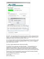
Precision Measurement Engineering, Inc. • www.Turner Designs.com
Fixed Sensor Cyclops-7 Logger User’s Manual
2013
Precision Measurement Engineering, Inc.
(760) 727-0300
www.Turner Designs.com
1
(INTENTIONALLY BLANK)
Precision Measurement Engineering, Inc.
(760) 727-0300
www.Turner Designs.com
2
Warranty
1-YEAR LIMITED WARRANTY
Precision Measurement Engineering, Inc. warrant that the Logger shall be free of
defects in workmanship and materials, under normal use, for a period of one year
from the date of shipment. This warranty is made only to the original purchaser. In the
event a Logger covered by this warranty fails to operate according to our published
specifications, then return it freight pre-paid to Precision Measurement Engineering or
an authorized Service Provider. Precision Measurement Engineering (PME) will
repair the unit at no charge to the customer and bear the cost of return shipment to
customer. Carefully pack all components, as the customer is responsible for any
freight damage.
This warranty does not apply to services or consumable / expendable items (such as
batteries, fuses and ropes) required for general maintenance. The Cyclops-7
sensor, manufactured by Turner Designs, is warranted only to the limit of the
warranties provided by their original manufacturer.
PME makes no warranty, either expressed or implied, that the sensors will be
operable after they are exposed to adverse environmental conditions, such as biofouling, oil fouling, freezing temperatures or others.
This warranty is void if, in our opinion, the Logger has been damaged by accident,
mishandled, altered, or repaired by the customer, where such treatment has affected
its performance or reliability. In the event of such treatment by the customer, costs for
repairs plus two-way freight costs (no COD shipments will be accepted) will be borne
by the customer. In such cases, an estimate will be submitted for approval before
repair work is started. Items found to be defective should be returned to PME
carefully packed, as the customer will be responsible for freight damage.
Incidental or consequential damages or costs incurred as a result of the product
malfunction are not the responsibility of PME.
For all warranty or non-warranty returns please obtain, complete, and submit a RMA
to PME. This RMA form may be obtained at
http://www.pme.com/HTML%20Docs/RMAform.html
After submission of this form, then PME will respond with a RMA number. Please
place this number on all shipments and related communications.
Precision Measurement Engineering, Inc.
(760) 727-0300
www.Turner Designs.com
3
Safety Information
BURSTING HAZARD
Should water enter the Cyclops-7 Logger and come into contact with the enclosed
batteries, then the batteries may generate gas causing the internal pressure to
increase. This gas will likely exit via the same location where the water entered, but
not necessarily. The Cyclops-7 Logger is designed to release internal pressure as
the end cap is unscrewed, prior to the disengagement of the end cap threads. If
internal pressure is suspected, then treat the Cyclops-7 Logger with extreme caution.
Revision History
Date
29-DEC-2011
10-JAN-2012
01-SEP-2012
14-DEC-2012
17-JAN-2013
11-FEB-2013
14-MAR2013
09-MAY-2013
28-AUG-2013
05-NOV-2013
11-NOV-2013
13-NOV-2013
19-NOV-2013
23-DEC-2013
24-DEC-2013
14-JAN-2014
20-MAR2014
20-MAR2014
2014SEP21
Revision Description
Copied from miniDOT manual (Revised 20-DEC-2011)
Added corrective action to LED flash table.
Updated for new RS232 software – extensively revised
Revised screen shots of Cyc7Calibrate and Cyc7Plot
Removed Sec 3.7 Serial port commands and Appendix 1
Pictures revised. Set Sample Interval description added
Added description of sensor type tag on SD card holder
Added more detailed description of calibration procedure. Added words
concerning Turner’s Solid Secondary Standard
Added battery pack warning
Reworded serial port driver to jspWin, removed Cyc7Service
Reworded Chapter 2 software installation
Removed Time Zone selection
Updated description of how time is set
Updated battery pack removal to remove SD card for ‘C’ pack
Updated to include exchangeable sensor
Replaced “exchangeable” with “interchangeable”
Corrected 2-flash reference to Sec 3.11 to reference 3.8
Updated to include “Fixed” in header name.
Removed information regarding Interchangeable logger. Created Fixed Logger
manual only.
Added sensor cover info to Sec 1.2 and added calibration description to Sec 2.4
Precision Measurement Engineering, Inc.
(760) 727-0300
www.Turner Designs.com
4
CONTENTS
Chapter 1 Quick Start
1.1 Calibrate and Go
1.2 A Few Details
Chapter 2 Software
2.1
2.2
2.3
2.4
Overview
Software Installation
Cyc7Plot
Cyc7Calibration
Chapter 3 Cyclops-7 Logger
3.1
3.2
3.3
3.4
3.5
3.6
3.7
3.8
3.9
Overview
Opening and Closing the Logger
Electrical Connections and Controls
Connection to Serial Port
File Close Button
Battery Replacement
File Management
SD Card
Interchangeable Sensor Installation
Precision Measurement Engineering, Inc.
(760) 727-0300
www.Turner Designs.com
5
Chapter 1: Quick Start
1.1 Calibrate and Go
Your Cyclops-7 Logger has arrived completely ready to go. PME produces two types
of loggers, one with sensor permanently installed and a logger with a connector that
you will use to plug in your own sensor. You have been provided with the Fixed
Cyclops-7 Logger, which contains a Cyclops-7 sensor that has been permanently
installed. The logger/sensor are shipped in an un-calibrated state. The logger itself is
set to measure temperature and concentration once every 10 minutes and record 4
files of measurements daily. You need only calibrate the sensor. In this condition the
Cyclops-7 Logger will operate for roughly half a year before the internal battery is
expended.
At the end of the deployment period you need only to open the logger, press the File
Close button, switch off the power, and remove the SD card. Your temperature and
concentration measurements, together with a time stamp indicating the time the
measurement was made, are recorded in text files in the DATA directory on the SD
card. These files can be copied from the SD card onto any host computer.
Files can be concatenated and displayed using the Cyc7Plot software supplied with
the logger.
Follow these steps to start the deployment, logging Cyclops-7 output and
Temperature once each 10 minutes:
1) Calibrate the sensor/logger as described in Chapter 2, Cyc7Calibrate program.
2) Open the Cyclops-7 Logger (if not already open from calibration) as described
in Chapter 3.
3) Slide the power switch to the ON. The LED will flash once. Observe the LED
for up to 90 seconds. Sometime during this period it will flash 5 times
indicating that logging has begun. If it flashes continuously, then see section
3.5 of this manual.
4) Inspect the o-ring seal for debris.
5) Close the Cyclops-7 Logger by screwing the white housing back onto the black
end cap.
6) Deploy the Cyclops-7 Logger.
Follow these steps to end the deployment
1) Recover the Cyclops-7 Logger
2) Clean and dry all accessible surfaces.
3) Open the Cyclops-7 as described in Chapter 3.
Precision Measurement Engineering, Inc.
(760) 727-0300
www.Turner Designs.com
6
4) Press the File Close button. The LED should begin continuous flashing.
5) Slide the power switch to the OFF position.
6) Remove the SD card (both screws must be removed to extract SD card). Use a
card reader and a host computer to copy the files located in the DATA directory
onto the host computer. These text files contain the measurements.
7) (Optional – but strongly recommended) Run Cyc7PLOT.jar program to see a plot
of measurements, and to produce a concatenated file containing all the
measurements. This file contains better time information and is much more useful
than the files collected directly by the logger.
Remove the battery if storing the Cyclops-7 Logger for extended periods.
1.2 A Few Details
The previous section gives instructions for sampling at 10-minute intervals. However
there are a few additional details that will enhance use of the Cyclops-7 Logger.
Sensor cover – The sensor guard is the long tube having slots in the end that covers
the Turner C7 sensor. This guard not only protects the sensor but also establishes a
consistent field of view for the sensor. The guard must be used when the sensor is
calibrated and also when it is used for measurements in the field.
Sampling rate – The Cyclops-7 Logger records measurements at equal time
intervals. The default time interval is 10 minutes. If a formatted SD card is placed in
the Cyclops-7 Logger and the power is turned on, then the logger will record every 10
minutes. However, it is also possible to instruct the Cyclops-7 Logger to record at
different intervals. This is accomplished by connecting a Windows computer to the
logger and using software supplied for this purpose. See Chapter 2.
Sample intervals of less than 1 minute or longer than 1 hour are not allowed and will
be rejected by the Cyclops-7 Logger software. The Cyclops-7 Logger will flash its
LED repeatedly if it encounters a sample interval request outside this range.
Sample Time – The Cyclops-7 Logger records the time that each is made. It does
this based on an internal clock. When your Cyclops-7 Logger arrives it is set by PME
to UTC (formerly known as Greenwich mean time (GMT)). We suggest that you
leave it always set to UTC so that there is never a time question in the recorded
measurements. Subsequent software implements conversion to local time. You can
reset Cyclops-7 Logger time to local time if you choose by using software. See
Chapter 2.
The Cyclops-7 Logger internal clock will drift in the <10 ppm range (< about 30
seconds/month) so you should plan to reset it occasionally.
File Information – The Cyclops-7 Logger software creates 4 files daily. The number
of measurements in each file will depend upon the sample interval. Files are named
Precision Measurement Engineering, Inc.
(760) 727-0300
www.Turner Designs.com
7
by the time (Unix epoch 1970) that the file is opened based on the logger’s internal
clock and expressed in hexadecimal format. (Use the Cyc7Plot program to
concatenate these files into a more useful format. See Chapter 2)
Cleaning the Sensor – The sensor may be cleaned by unscrewing the black sensor
guard and gently wiping the optical face.
Battery Life – The Cyclops-7 Logger consumes battery power mostly from the
Cyclops-7 sensor, but also slightly from simply keeping track of time, writing files,
sleeping, and other activities. The Cyclops-7 Logger will record approximately
30,000 total samples and will operate for up to a year when powered by the battery
pack (2 X alkaline ‘C’ cells) supplied by PME.
Keep a general record of Cyclops-7 Logger number of samples. It is not possible to
accurately determine the charge state of the battery pack from measurements of its
terminal voltage. If you have a general idea of the number of samples already
obtained on a battery, then you can make a guess as to how many more samples
remain. Err on the side of caution.
The 2 X ‘C’ battery pack holds the batteries very tightly. The holder itself is glued to
the aluminum chassis. Take care when changing batteries that the glue joint is not
broken. Always use the paper tube supplied with the Cyclops-7 to contain the
batteries. Use only new batteries as replacements.
Coin Cell Battery Life – The Cyclops-7 Logger uses a coin cell for backup of the
clock when the power is switched off. This coin cell will supply roughly 2 years of
clock operation, but this is only required if the main power is off. Should the coin cell
discharge it must be replaced. Coin cells are not user-replaceable.
O-Ring and Seal – When the cover is screwed on, it passes along the o-ring located
in the end cap several revolutions. Keep this o-ring lightly lubricated with silicone
grease or oil compatible with buna-N o-ring material.
When the Cyclops-7 Logger is opened after deployment, a small number of water
drops are deposited on the inner surface of the o-ring. When the pressure housing is
screwed back on, these drops become trapped inside the Cyclops-7 Logger. Be sure
to carefully dry the o-ring and adjacent surfaces (especially underneath) prior to
closing the Cyclops-7. Re-lube the o-ring at this time. Remove any debris from the
drying process.
Closing the Logger – The logger is much more difficult to open than to close. Screw
the white logger housing onto the black cap until the housing touches the cap. No
further tightening is necessary.
SD Card – If the retaining screws are lost or not re-installed, the SD card can be
ejected from its socket if the Cyclops-7 Logger is dropped on its pressure housing
end. The logger will be unable to log should this occur. If the retaining screw is lost
Precision Measurement Engineering, Inc.
(760) 727-0300
www.Turner Designs.com
8
the SD card can be taped in place using a bit of electrical tape. Use only SanDisk 2
GB SD cards as replacements.
THE SD CARD IS NOT HOT-SWAPPABLE. POWER MUST BE SWITCHED OFF
PRIOR TO INSERTING OR REMOVING THE SD CARD. IF THIS IS NOT DONE,
DAMAGE TO THE SD CARD MAY RESULT.
LED Indications – The Cyclops-7 Logger performs various tests as it begins logging
operations. If any test fails the software flashes the LED light and re-conducts the
test. In general if a test fails once it will continue to fail and the LED light will
continue to flash. The following table gives the number of flashes and the reason
these flashes appear.
LED
Flash #
1
2
3
4
5
Reason
Corrective Action
Normal. Presented immediately
after power is switched on.
Indicates that the CPU has
started its program.
Error. No SD Card or SD card
not completely plugged in.
None required. Normal operation.
Error. Requested sampling
interval less than 1 minute or
greater than 1 hour.
Error. Clock not initialized.
Normal, presented once after
roughly one minute, indicating
that the miniDOT Logger is
starting logging operation.
Plug SD card correctly. Install new
SD card. Re-format SD card (Sec
3.8)
Check CAL.TXT file on SD card
(Sec 1.2).
Reset clock (See TIME command
Sec 3.9 and Appendix 1).
None required. Normal operation
In addition to LED flashing, the Cyclops-7 Logger internal software prints statements
while doing internal testing just after the power is switched on. These statements can
supply more information than the LED flashes. See Section 3.5 for additional
information.
Precision Measurement Engineering, Inc.
(760) 727-0300
www.Turner Designs.com
9
AutoRanging – The Cyclops-7 sensor has three output ranges: 1X, 10X and 100X.
The best of these ranges is automatically selected by the logger based on the voltage
measured of the sensor. The logger software remembers the best range and, at
each sample time, first measures sensor output voltage using this range. Software
then reviews this voltage to determine if the range was appropriate. In most cases
the range will be appropriate and the measurement is recorded. However sometimes
software determines that a different range would yield a better measurement. In this
case software selects a new “best range” and re-measures the sensor output voltage
using this range. This new best range becomes the range selected at the next
sample time. The best range is determined as follows:
Sensor Voltage Divided by Range
0.00 to 0.04
0.04 to 0.4
0.4 and higher
Best Range
100X
10X
1X
Should the first voltage measurement be unacceptably close to the sensor maximum
output voltage (an over-range condition) the first voltage is re-measured using range
of 1X and the best range calculated. This range becomes the best range and
software proceeds as above.
Calculation of Engineering Units – Engineering units are calculated from voltage
measurements of the sensor and from information gained during calibration (see
Chapter 4). The result of calibration is the following information:
Name
Vz1
Vz10
Vz100
S
Definition
Voltage output of sensor in zero solution on
range 1X
Voltage output of sensor in zero solution on
range 10X
Voltage output of sensor in zero solution on
range 100X
Sensitivity of sensor
Vz1, Vz10, and Vz100 are measured with the sensor in a solution of zero
concentration. S is determined from the voltage output of the sensor using the “best
range”, described above, with the sensor in a reference solution of known
concentration. The user must enter the concentration value of this solution, given the
name C. The sensor voltage is measured in this solution and given the name Vs.
The following table shows how S is determined.
Range
1X
10X
100X
S
S = C / (Vs – Vz1)
S = 10.0 * C / (Vs – Vz10)
S = 100 * C / (Vs – Vz100)
Precision Measurement Engineering, Inc.
(760) 727-0300
www.Turner Designs.com
10
Note that since only one calibration concentration is actually measured, there is only
one S determined. However this S is used to compute engineering units from the
other ranges should these be implemented by the logger during the measurement of
samples.
Engineering units are computed as shown in the following table:
Range
1X
10X
100X
EU
EU = S * (Vs – Vz1)
EU = S * (Vs– Vz10) / 10.0
EU = S * (Vs– Vz100) / 100.0
Engineering units computed using the same range that was used to determine S will
be more accurate than engineering units computed using other ranges since the
sensor may not exactly implement ranges. For example the 100X range may
actually be implemented by circuitry as 100.1X but the calculations would use 100X.
Precision Measurement Engineering, Inc.
(760) 727-0300
www.Turner Designs.com
11
Chapter 2: Software
2.1 Overview
The Cyclops-7 Accessory Kit includes software to calibrate the sensor, and
concatenate and display Cyclops-7 Logger data files. These programs are designed
to operate on a Windows computer.
2.2 Software Installation
Software operation requires a Windows operating system computer. Both 32 and 64
bit computers are supported.
Install the software by copying the files below into any folder on your computer’s hard
drive.. There are four files and two folders:
•
•
•
•
•
Cyc7Plot.jar – Concatenate logger data files and plot.
Cyc7Calibration.jar – Facilitate calibration of sensor.
jspWin.dll – library of java RS232 software interface to Windows operating system
(32-bit is the default)
32 Bit PC Serial Driver folder
64 Bit PC Serial Driver folder
Cyc7Plot and Cyc7Calibration are Java language programs that require the host
computer to have the Java Runtime Engine V1.6 or later installed. This engine is
commonly required for internet applications and will likely already be installed on the
host computer. Should this not be the case the JRE can be downloaded via internet
from
http://www.java.com/en/download/inc/windows_upgrade_xpi.jsp
Cyc7Calibrate communicates with the host computer’s serial port. It requires a serial
port driver, jspWin.dll. The jspWin.dll in the files supplied is the 32 bit version. If your
computer is operating a 64 bit JRE, delete jspWin.dll. In it’s place copy the jspWin.dll
from the 64 Bit PC Serial Driver folder. The correct (32 or 64 bit) jspWin.dll must be
present in the same folder as Cyc7Calibrate.
If your computer does not have a serial port (these are called COM ports on Windows
computers) you must supply a serial-to-USB adapter. These are supplied by PME or
can be purchased from some other source. These adapters usually require that you
install a driver. For PME’s adapter follow instructions supplied with the adapter.
Click on Cyc7Plot or Cyc7Calibrate to run the program.
2.3 Cyc7Plot
Precision Measurement Engineering, Inc.
(760) 727-0300
www.Turner Designs.com
12
Cyc7Plot performs two services:
•
•
It concatenates all the measurement files it finds in the selected directory and
writes these as CAT.TXT, and
it displays the concatenated measurements.
When Cyc7Plot runs it presents the screen shown below.
Select the DATA folder. This is the folder that contains your Cyclops-7 Logger
measurement files. This folder MUST NOT contain any other files. This folder can
be on the SD card from the Cyclops-7 or it can be from a copy of this on your
computer’s hard drive.
Press ‘Process’ to begin measurement processing. The software reads all Cyclops-7
Logger data files in the Data Folder, writes a CAT.TXT file in the same folder, and
finally presents a plot of the measurements similar to the plot shown below.
Example CAT.TXT file:
Precision Measurement Engineering, Inc.
(760) 727-0300
www.Turner Designs.com
13
You may zoom this plot by drawing a square from upper left to lower right (click and
hold left mouse button) that defines the zoom region. To zoom completely out,
attempt to draw a square from lower right to upper left. Right click on the plot for
options such as copy and print.
The software may be run multiple times at the same time (select Data Folder, press
Process, select new Data Folder, press Process...). In this case it produces multiple
plots. Presently the plots are presented exactly on top of each other and so when a
new plot appears it is not obvious that the old plot is still there. It is. Just move the
new plot to see it. Closing any plot closes all.
The software can be re-run at any time. In this case it simply reads the Cyclops-7
Logger measurement files again and, after asking permission, overwrites the
CAT.TXT file.
2.4 Cyc7Calibrate
The Cyc7Calibrate program provides these services:
•
•
•
It enables time setting (based on internet timeserver clock),
it enables sample interval setting,
and it enables calibration of the sensor.
Turner C7 sensors, and PME loggers, are not factory calibrated. Calibration must be
physically performed by the customer. Calibration consists of an experiment where
Precision Measurement Engineering, Inc.
(760) 727-0300
www.Turner Designs.com
14
the sensor is exposed to two solutions, the first having 0 concentration of the sensed
material (chl-a, rhodamineP whatever the C7 sensor senses) and a second solution
having a known concentration created by the customer. Cyc7Calibrate software
records sensor output in each solution and creates a linear fit to these two points.
After calibration the Cyclops 7 Logger will measure sensor output and record it in
engineering units using this linear fit.
Turner C7 sensors are optical devices that operate by sending colored light into the
water and observing how much light returns. The field of view available to these
sensors is quite important in establishing their response. PME’s Cyclops 7 Logger is
supplied with a sensor cover that not only protects the sensor from damage but also
establishes the field of view. This cover has slots near where it covers the sensor so
that exterior water can enter and be sensed.
The sensor cover must be in position when the sensor is calibrated and must be in
the same position when the sensor is used.
A small amount of light can exit through the sensor cover slots, be reflected by the
container holding the calibration solution, and return. Calibrate the sensor in black
containers.
Exterior light such as room lighting or sunlight can enter through the slots and cause
a very small measurement effect. Attempt to calibrate in the same lighting as the
system will experience in field use.
Be sure that there are no bubbles trapped in the cover or stuck on the sensor.
Calibration proceeds by dipping the system in one solution and then the next. Take
care not to transport one solution to the next. Mix two 0 solutions and two solutions
of the sensed material. Label one each as the “calibration” and one each as the
“wash” When moving the sensor back and forth first dip the sensor in the wash then
into the calibration. The most noticeable effect is when the 0 solution is contaminated
prior to calibration. If the 0 solution is really 1, and if this is not noticed and the value
0 is entered into Cyc7Calibrate, then later in a truly 0 solution the Cyclops 7 Logger
will be indicated as a concentration of –1. A negative concentration can not exist and
so the sensor is suspected of poor measurement when the problem really is that it
was poorly calibrated.
Cyc7Calibrate requires that the host computer be connected to the Cyclops 7 Logger
at the time the calibration is performed. The logger must be open at this time. Take
care that no calibrating solutions splash onto logger circuits.
When calibration is completed, use the sensor to log measurements in each
calibration solution. Do this right away using the same solutions that were used for
calibration. The values 0 and the known concentration should be recorded. This
gives a check on the results of calibration.
Cyclops-7 Loggers support various Turner Cyclops-7 sensors. The sensor type is
shown on a small tag on the SD card holder.
Precision Measurement Engineering, Inc.
(760) 727-0300
www.Turner Designs.com
15
When Cyc7Calibrate runs it first displays the following dialog.
Yes, the software really means it! The Cyclops-7 Logger MUST FIRST be connected
to the computer COM port (or to a USB-to-COM adapter that is itself already
connected to the computer with proper driver installed) and THEN the logger power
turned on. When the logger is powered its internal software first checks to see if the
logger is connected. If so, software becomes responsive to commands and presents
a steady LED indication, if not software begins logging measurements and will NOT
respond to Cyc7Calibrate commands.
See Chapter 3 for instructions on opening the logger and connecting the serial port.
After “OK” is pressed the Cyc7Calibrate user interface appears”
Precision Measurement Engineering, Inc.
(760) 727-0300
www.Turner Designs.com
16
The first task is to connect to the Cyclops-7 Logger. This is accomplished by
selecting the COM port (or to a USB-to-COM adapter) where the logger is connected.
Connection is accomplished in response to the Connect button. Upon successful
connection the button turns green and various information is read from the logger.
If the host computer is connected to the internet, the current difference between an
internet time server’s time and the Cyclops-7 Logger internal clock will be displayed
next to the Set Time button. If this difference is acceptable the clock need not be set.
If the computer is not connected to the internet a message will appear and the Set
Time button will not be enabled.
To set the clock, click on the Set Time button. Software will set UTC time based
upon an internet time server’s clock. Time set will replace the time error displayed.
The Cyclops-7 sampling interval is set in response to the Set Sample Interval button.
Enter the desired interval and click on the button. The value shown initially is the
current value read from the logger.
Precision Measurement Engineering, Inc.
(760) 727-0300
www.Turner Designs.com
17
Sensor calibration requires that you provide two reference solutions. One solution
will be the ‘zero’ (sometimes called the ‘blank’) solution and will contain none of the
material being sensed. The other solution, the ‘calibration’ solution, will contain a
known quantity of the material being sensed. It may also be that the calibration is a
solid standard. This calibration quantity must be no more than the measurement
range of the sensor on its 1X scale but it can be less. See Chapter 1 for a description
of sensor ranges.
Sensors are calibrated in response to the Calibrate button, after both the Unit of
Measure and the Calibration Value are entered.
Enter the unit of measure that is appropriate for the Cyclops 7 sensor mounted on the
logger.
Enter the calibration value for the solution.
Click on the Calibrate button. The adjacent scroll bar shows how far the program has
progress through the calibration procedure.
Precision Measurement Engineering, Inc.
(760) 727-0300
www.Turner Designs.com
18
A dialog window appears instructing you to place the sensor in the zero solution.
This will most likely simply be clear water contained in a bucket. Whatever the
solution, the sensor after calibration will report 0 when returned to this solution. Click
OK when the sensor is suitably positioned.
At this time the software reads information from the sensor, selecting all three ranges
of the sensor sensitivity.
Precision Measurement Engineering, Inc.
(760) 727-0300
www.Turner Designs.com
19
When this is completed a Zeroing of sensor completed dialog appears. Click OK.
Precision Measurement Engineering, Inc.
(760) 727-0300
www.Turner Designs.com
20
A “Please place sensor in calibration solution of <Calibration Value> (<Unit of
Measure>)” dialog appears. In the screen shot above the value of 50.0 (NTU) is
displayed. This information is taken from the Unit of Measure and Calibration Value
text boxes and will be whatever is entered in the boxes.
Place the sensor in the calibration solution. Whatever the solution, the sensor after
calibration will report the calibration value (50 NTU in the above example) when
returned to this solution.
Click OK. At this time the software reads information from the sensor, selecting the
best sensitivity range.
When this is completed a “Calibration completed” dialog window appears along with
the actual calibration results.
Precision Measurement Engineering, Inc.
(760) 727-0300
www.Turner Designs.com
21
Click OK. You may (and should!) now save the results on disk by clicking the Save
Results. Note that the calibration has been installed in the sensor and the sensor is
calibrated no matter if the results are saved on disk or not.
If you choose to save the results a file save dialog appears. You must create a name
for the calibration file, including the appropriate suffix. The .txt suffix is suggested
since software saves a text file.
You may read the saved file later using a text file editor.
A note about Turner solid state secondary standards: These standards are not
supplied with any calibration value, so they are not at first useful for calibration.
However, once the sensor is calibrated the solid state secondary standard can be
placed onto the sensor and adjusted so that the sensed value is some arbitrary value.
Please refer to Turner’s documentation concerning the Solid Secondary Standard
that is supplied with the standard or via the internet:
Precision Measurement Engineering, Inc.
(760) 727-0300
www.Turner Designs.com
22
http://www.turnerdesigns.com/t2/doc/instructions/998-6800.pdf
Install the standard as described. The logger’s sensor guard must be unscrewed and
removed for this procedure.
Operationally, adjustment of a standard is not well implemented in the logger
software. Step 2 of theUse of the Solid Secondary Standard for in vivo Chlorophyll
Applications on page 1 of this document assumes that the sensor output can be
viewed in real time. However this output can only be logged by the Cyclops-7
Logger. A short recording of the measurement must be made, and then the record
reviewed, to determine the sensed value. The process must be repeated by trials to
adjust the standard as described in the document.
Precision Measurement Engineering, Inc.
(760) 727-0300
www.Turner Designs.com
23
Chapter 3: Cyclops-7 Logger
3.1 Overview
All of the Cyclops-7 Logger measurements pass from the sensors onto the SD card it
contains. Measurements may flow from the logger to host computer by removing the
SD card and copying the contents. Customers will be required to open the logger
each time measurements are obtained. This chapter describes the logger internal
features.
3.2 Opening and Closing the Logger
The logger circuitry is contained in a waterproof housing that must be opened. The
housing is opened by unscrewing the white pressure housing from the black end cap.
Turn the pressure housing counter clockwise relative to black end cap. Close by
reversing this procedure after being sure that the o-ring is free from debris. Lube oring occasionally with grease intended for buna-n o-ring material.
The logger is much more difficult to open than to close. Screw the white logger
housing onto the black cap until the housing touches the cap. No further tightening is
necessary.
Precision Measurement Engineering, Inc.
(760) 727-0300
www.Turner Designs.com
24
3.3 Electrical Connections and Controls
Removal of the cover reveals the logger connections and controls, shown below.
The SD Card contains data files and the calibration file. These are described
elsewhere in this manual. Note that the battery pack and one screw must be
removed to remove the SD card.
The LED Light is a yellow LED. This is used to indicate different features described
elsewhere in this manual.
The File Close Button causes the program to save the current file and halt
measurement logging. Press this button prior to switching power off. If you switch off
without pressing this button nothing really bad happens but the last file that could
contain up to 6 hours measurements will be forgotton.
The Serial Port Connection allows communication between the logger and an
external computer. Communication parameters are 9600 baud with 8 bits, no parity,
and one stop bit. The external computer must have a communication program such
Precision Measurement Engineering, Inc.
(760) 727-0300
www.Turner Designs.com
25
as Hyperterminal (for PC) or equivalent, a connecting cable, and must have a serial
port or USB to serial adapter. The Cyc7Calibrate and Cyc7Service programs use this
connection. Plug the connection cable supplied with the Cyclops-7 Logger into this
connector. Plug opposite end to the host computer’s COM port.
The On/Off Switch connects or disconnects battery power to the logger. In the ‘Off’
position the logger is completely without power except for the clock circuit. Note that
‘On’ and ‘Off’ positions are marked in white letters on the circuit board nearby the
On/Off Switch.
The Main Battery provides main power to the Cyclops-7 Logger.
3.4 Connection to Serial Port
The Cyclops-7 Logger must be connected to a host computer to use the
Cyc7Calibrate and Cyc7Service software. It can also communicate with a terminal
program such as Hyperterminal.
Connect the Cyclops-7 Logger to a host computer by plugging the connection cable
into the RS232 connection within the Cyclops-7 Logger. Connect the opposite end
(9-pin D connector) to the host computer’s serial port. On a PC desktop this is the
COM port. Some computers may not implement a COM port in which case the serial
Precision Measurement Engineering, Inc.
(760) 727-0300
www.Turner Designs.com
26
port must be emulated by using a USB to Serial converter. PME supplies a serial-toUSB converter in the Cyclops-7 Accessory Kit.
In addition to the physical connection, the host computer may run a terminal program
such as Hyperterminal. Windows 2000 and XP ship with Hyperterminal located at
programs|accessories|communication. Later Windows operating systems do not.
The Cyclops-7 Logger communicates as shown in the table below. Appendix 1
shows how to set Hyperterminal for this protocol and gives other information about
communications programs.
In general, Customers should not need to use software besides Cyc7Calibrate to
communicate with the Cyclops-7 Logger.
Feature
Baud Rate
Bits sent per
byte
Parity
Stop bits sent
Flow control
Parameter
9600 (bits/second)
8 (bits)
none
1 (bit)
none
3.5 File Close Button
The logger records individual measurements to the SD card file when the
measurement is made. After each measurement the file remains open. If the power
fails or is switched off while the file is open, then the file information is lost. Files are
recorded 4 times daily so only as much as 6 hours of measurements are at risk. The
user must inform the Cyclops-7 software that the power is about to be switched off by
pressing the File Close button. The software will detect this action and close the
presently open file. Thereafter the logger will halt its mission, flash its LED
repeatedly.
There is no way to exit this loop except by turning the logger power off.
3.6 Battery Replacement
Carefully remove both “C” cells, noting the direction of the (+) terminals. These both
are oriented towards the SD card and circuit. Insert new ‘C’ cells into the paper tube
and re-install the pair into the battery holder. Take care not to break the glue
connection between the holder and the aluminum chassis.
3.7 File Management
The Cyclops-7 Logger writes 4 data files daily onto the SD card. These are text files
that contain the measured data. These files contain the serial number of the
Precision Measurement Engineering, Inc.
(760) 727-0300
www.Turner Designs.com
27
Cyclops-7 Logger that wrote the file and also a time stamp for each measurement.
The Cyclops-7 Plot software reads all these files and produces a CAT.TXT file that
contains the original data plus extra information.
The recommended method of file management is the following:
1) Deploy the Cyclops-7 Logger for a period, and recover it.
2) Remove the SD card and place in a card reader on a host Windows computer.
3) Run Cyclops-7 Plot, selecting the DATA directory on the SD card. This creates
the CAT.TXT file in the SD card DATA directory.
4) Create a folder on the host computer for this Cyclops-7 Logger deployment. Copy
all files in the SD card DATA directory to this folder. Keep deployments of the
same Cyclops-7 logger in separate folders. Keep files from separate Cyclops-7
sensors separated as well.
5) Delete all files in the SD card DATA directory.
File management may be handled in other ways, but in any event be sure that the SD
card DATA folder is empty prior to beginning a deployment. If it is not empty nothing
bad happens but unpredictable Cyclops-7 Logger operation may occur if the number
of files becomes large, roughly over 1000 files.
3.8 SD Card
THE SD CARD IS NOT HOT-SWAPPABLE. POWER MUST BE SWITCHED OFF
PRIOR TO INSERTING OR REMOVING THE SD CARD. IF THIS IS NOT DONE,
DAMAGE TO THE SD CARD MAY RESULT.
Cyclops-7 is supplied with a 2 GB SD card. Alternates can be purchased and used
with Cyclops-7. Use only SanDisk 2 GB SD cards. Cards manufactured by other
manufacturers may work also but PME has tried SanDisk. In any event use only 2
GB capacity cards.
Format every card prior to using with Cyclops-7.
Format cards only on a PC computer running a Windows operating system. Other
computers or operating systems may work but PME has tried only Windows.
When formatting, select FAT, not NTFS or FAT32. Do not provide a volume label nor
select Quick Format. Here is the correctly set Windows 2000 Format dialog:
Precision Measurement Engineering, Inc.
(760) 727-0300
www.Turner Designs.com
28
The SD card is retained by a small screw that must be removed prior to removing the
SD card. If the retaining screw is lost, the SD card can be ejected from its socket if
the Cyclops-7 Logger is dropped on its pressure housing end. The logger will be
unable to log should this occur. If the retaining screw is lost the SD card can be
taped in place using a bit of electrical tape.
Precision Measurement Engineering, Inc.
(760) 727-0300
www.Turner Designs.com
29