1
Filed on behalf of:
Medtronic, Inc.
UNITED STATES PATENT AND TRADEMARK OFFICE
BEFORE THE PATENT TRIAL AND APPEAL BOARD
Medtronic, Inc.
Petitioner
V
NuVasive, Inc.
Patent Owner
Case
U.S. Patent No. 8,016,767
DECLARATION OF DAVID HACKER
MSD 1015
1015
MSD
1, David Hacker of Duval County, Jacksonville, Florida, declare that:
1.
I am the Principal Engineer, Research and Development, for Medtronic, Inc.,
in the Surgical Technology Division. I have worked as an engineer on Nerve
Integrity Monitor (NIM) systems for surgical applications since 1989.
Specifically, from 1989 to 1999, I worked on NIM systems for Xomed, Inc. In
1999, Xomed, Inc. was acquired by Medtronic, Inc. I have continued to work on
NIM systems for Medtronic, Inc. since that acquisition.
2.
My work on NIM systems has involved reviewing user manuals that are
provided with the NIM products sold by Medtronic, Inc. (and previously Xomed,
Inc.). These user manuals are shipped with the corresponding product to
customers who buy the product.
3.
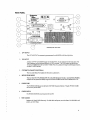
Being submitted with this Declaration as Attachment A is one such manual,
which is entitled NIIVI-Response — Nerve Integrity Monitor/Intraoperative EMG
Monitor — User’s Guide (“User Guide”). The User Guide was a user manual for
the NIM-Response 82-50001 Mainframe product (“NIM-Response product”) and
was shipped with the product to customers.
4.
The User Guide has a copyright date of 2000 on the page following the title
page. I note that the User Guide has a date of “03/00” on the last page. This
indicates that this version (Revision B) of the User Guide was finalized in March
2000. The User Guide also has a handwritten “4/4/2000” notation at the top of the
title page. This indicates that the User Guide was approved for release with the
corresponding product on April 4, 2000.
5.
In addition, I have attached a copy of a Work Order for the NIM-Response
product as Attachment B to this Declaration. Work orders document the date that a
product was built and includes, among other things, the first and last page of the
l
user manual that is included with the product when the product is shipped. The
attached Work Order is for a NIM-Response product built in May 2000 and has a
Lot No. 19727500. The first and last page of the manual attached to the Work
Order confirms that the manual shipped with the product was the same User Guide
as Attachment A. The date stamped at the bottom of the Work Order indicates that
the NIM-Response product with this particular User Guide was built and ready for
shipment on May 26, 2000.
6.
I attach as Attachment C to this Declaration, a Sales Record for the NIM-
Response product for May 26, 2000. I note that the Lot No. is the same as that of
the Work Order above, Lot No.l9727500. This Sales Record confirms that on
May 26, 2000, the product and the accompanying User Guide was shipped to
customers.
7.
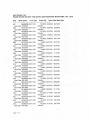
I have also attached a copy of the Work Order History from 2000-2001 for
the NIM-Response product as Attachment D to this Declaration. The Work Order
History shows that the NIM-Response product was continuously built and shipped
(with accompanying manual) throughout 2000-2001. At least as early as May 26,
2000, the manual shipped with the product was the User Guide.
8.
Thus, based on my review of the User Guide, Work Order, Sales Record,
and Work Order History, the User Guide was provided to customers, outside of
Medtronic, Inc., who bought the corresponding product, at least as early as May
26, 2000. Those customers included hospitals and clinics in the United States and
other countries. Medtronic, Inc. did not restrict the customers’ use or
dissemination of the User Guide.
9.
I hereby declare that all statements made herein of my own knowledge are
true and that all statements made on information and belief are believed to be true;
and further that these statements were made with the knowledge that willful false
2
statements and the like so made are punishable by fine or imprisonment, or both,
under Section 1001 of the Title 18 of the United States Code.
Date: /C-7'/.5) '.»~,7['/ .
David Hacker
ATTACHMENT A
A
ATTACHMENT
f\;>§>mr£o\% W0Q I,/I/LI;
NIM-Response” I
NERVE INTEGRITY MONITOR
'
-lntraoperative EIVIG Monitor
USER’S GUIDE
NIM-Response Helplilic
I-800-874-5 7
For Questions aI ‘ rvicc
Copyright 2000 Medtronic Xomed Surgical Products. inc.
All Rights Reserved
Made in U.S.A.
_ MEDTRONICXOMEDSURGICALPRODUCTS, INC.
6743 Southpoint Drive Nonh
Jacksonville, FL 322 I6
Datalight is a registered trademark of Datalight, Inc. .
ROM-DOS is a trademark ofDatalight, inc.
iCopyi'ight I989-1999 I)atal-ighl, Inc., All Rights Reserved
Cۤ
—-wa.u_,»~4
This device complies with Medical Device Directive 93/42/EEC
Authorized Representative (for EC regulatory matters)
Medtronic Xomed U.K. Limited
Unit 5, West Point Row
Great Park Road, Almondsbury
Bristol B532 4QG
England
'-24’~.:*t9,;‘_"Nx
‘3i'-:$«~sm.2,1zg—e!r?="
“TM” are trademarks oi’Medtronic Xomed Surgical Products, Inc.
‘ags-xe’‘
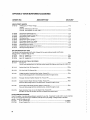
CONTENTS
Symbols ...................... ..'........................................................... ................................ ii
Warnings And Precautions ............... .................................................................... .. iii
Customer Service ................ ..
‘
Warranty ..................................................................................... ........... ........... .. vi
1 - Getting Started
Device Description
Intended Use ............ ..
indications
Contraindications ..................................................................................................... .. 1
Components .................... ............................................................................ ..'. .......... l
Operating Room Setup
.. 2
Location .................................................................... ..
.
2
Front Panel
........................................... ..
2
Rear Panel . . . . . . . . . . .. .
. . . .. . . . . .
. . . .. 3
Software Setup . . . . . . . .
. . . . . . . . . . . . . . . . ..
. . . .. 6
Monitoring Screen ..
6
Event Threshold ....................................................................................................... .. 7
Auto Event Threshold ...................{. ........................................................................ .. 7
Main Menu .....................
8
Reference Channel ................................................................................................. .. I0
Quick Set-Up Menu ................................................................................................ ..
Customize Menu ....... ..
.... ..
Stimulus Subincnu
Voices Submenu .... ..
......
Tones Submenu ........................................................................................................
Clock Submenu ....................................................................................................... ..
Research Tools Submenu .. . . . . . . .. . . . .
. . . .. . . . . . . . . . .. . . ..
ll
I2
l2
I3
I4
15
16
2 - Using The NIM—Response
l8
Anesthesia Requirements ............................................... .; ............................... ...... 18
1'-.‘.lectrode Selection
..... ..
l8
Electrode Placement . . . . . . . . . . .. . . . .
. . . . . . . . . ..
18
Stimulator Probe Connection .. . . .
. . . . . . . . . ..
I9
System Checks And Tests
................................................................................. ..
Electrode Impedance Checking ............. .................... .... ................................ ..
Adjusting The Event Threshold ............... ..
’
When l':'lectrocautc1y And Cusa Are Used ............................................................ ..
Understanding What You Hear .................................................. .:...... ..‘.................. ..
interpreting The Alarms . . .. . . . . . . . .
. .. . . . .
. . . . . . . .. . .
. . . . ..
When The Case is Complete
..
When Monitoring ls Complete...
.................. ..
I9
l9
2i
21
.3
.3
B
3 -Troubleshooting
4 - Maintenance And Service
Preventive and Corrective Maintenance ................................. ..
24
..
Appendices
.....
Appendix A ° Glossary & Quick Reference Terms ...................................................
Appendix B - Nerve Monitoring Accessories ......... ..
Appendix C ' Approved Output Devices
.... ..
Appendix‘D v Technical Specifications . .. . .. . .
. . ....
Appendix E - Agency Approvals ........................................................................... ..
Appendix F - References ........................................................................................ ..
26
26
28
28
32
35
36
38
:9
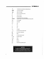
SYMBOLS
A'I'TENT|ON, SEE INSTRUCTIONS FOR USE
CATALOG NUMBER
SERIAL NUMBER
DATE OF MANUFACTURE
USE BY DATE
DO NOT REUSE
S'I‘ERII.IZED BY ETHYLENE OXIDE.
DO NOT USE IF PACKAGE IS OPENED OR DAMAGED.
LOT NUMBER
CE MARK
OFF
oN
OFF
oN
VOLUME
RI.-‘.LA'I‘IVE SCALE INDICATOR
EXIT POP-UP WINDOW
I-II:~:I..I>
’l‘YPF. BF APPLIED PART
PATIENT CABLE
FUSE
INPUT
OUTPUT
F OOTSWITCH CONN ECTION
ii-
s-.,~«
A
WARNINGS AND PRECAUTIONS
It is important that the NIM-Response operator be familiar with this manual: its precautions,
procedures and safety issues. Three labels are used in this manual to identify important concerns.
conrlitions, or procedures:
“A WARNING”
Idctitifies conditions or practices that present a risk of injury to the patienl and.’or user.
“A CAUTION I PRECAUTIONS”
Identifies conditions or practices that could result in damage to the equipment.
“A IMPORTANT"
Identifies conditions or practices which require attention for most dcsirahie monitoring results.
' A WARNINGS
'
-
THE UsE OF PARALYZING ANESTHETIC AGENTS WILL SIGNIFICANTLY REDUCE, IF NOT COMPLETELY
ELIMINATE, EMG RESPONSES TO DIREcT oR PAssIVE NEURAL STIMULATION.
AUDITORY AND vIsuAL MONITORING ARE DISABLED wHILE MUTING IS IN EFFECT.
THIS SYSTEM IS NOT EXPLOSION-RESISTANT. THEREFORE, IT IS NOT TO BE USED IN THE PRESENCE OF
FLAMMABLE ANEsTHETIcs.
TO MINIMIZE THE RISK or BURNS TO THE PATIENT INCLUDING CASES wHERE MoRE THAN ONE SURGEON IS OPERATING (I.E. FAT HARVESTING), NEVER LEAVE THE STIMULATOR IN THE FIELD, ON A
MAGNETIC TRAY, oR IN THE ELECTROSURGICAL HOLDER DURING ELECTROSURGICAL USE.
-
To AVOID EYE INJURY DURING ELEcTRoDE PLAcEMENT, THE ELEcTRODE NEEDLES sHOULD BE
DIRECTED AWAY FROM THE ORBIT WHEN INsERTED FOR oREIcULARIs ocuLI MONITORING.
DO NOT TURN POWER TO THE N|M—REsPONsE ON wHEN THE sTIMULAToR Is IN'THE FIELD. UPON
APPLICATION OF POwER, A PULSE OF 5 MA MAY BE DELIVERED FOR LEss THAN 0.01 S. THIs MAY BE
EXCESSNE FOR SOME MONITORING APPLICATIONS.
v
ANY coNNEcTIoNs MADE TO LPT1 OTHER THAN THE THOSE RECOMMENDED IN THIs MANUAL, MAY_
NOT BE ISOLATED AND RESULT IN INJURY TO THE PATIENT oR OPERATOR.
-
THE NIM—REsPONsE DOES NOT PREVENT THE SURGICAL sEVERANcE OF NERVES. MONITORING Is
oNLY A TECHNICAL AID To IDENTIFICATION AND LOCATION or NERVEs; IT DOES NOT REPLACE THE
SURGICAL SKILLS, EXPERIENCE, AND ANATDMICAL KNOWLEDGE NECESSARY To VISUALLY LOCATE
NERVES AND SURGICALLY -AVOID THEIR SEVERANCE.
A PRECAUTIONS
.
v
Do NOT cONNEcT ANY DEVICE oTHER THAN NIM-REsI>DNsE MUTING PROBES INTO ANY OF THE
FOUR MUTING PROBE INPUTS oN THE REAR PANEL OF THE NIM-RESPONSE. SYsTEM DAMAGE
_ MAY RESULT.
.
DO NOT MODIFY THE NIM—REsPoNsE OREXTEND THE CABLES or THE MUTING PROBE OR
PATIENT INTERFACE. SUCH MODIFICATIONS OR EXTENSIONS COULD SIGNIFICANTLY AFFECT
SYSTEM PERFORMANCE.
~
-
TURN OFF POWER TO THE NIM—REsPoNsE OR
PREVENT CLEANING SOLUTIONS FROM SEEPING
SPRAY CLEANER LIGHTLY ON A COTTON CLOTH,
ESPECIALLY CAREFUL AROUND THE CONTROLS,
ABRASNE CLEANERS.
NIM-R_EsPoNsE PRINTER BEFORE CLEANING. To
INTO THE ELECTRONIC PORTIONS OF THE INSTRUMENT,
THEN WIPE THE INSTRUMENT WITH THE CLOTH. BE
CONNECTORS AND PANEL EDGES. DO NOT USE
V
°
ATTEMPTED REPAIR OR EVIDENCE OF ATTEMPTED REPAIR BY ANYONE OTHER THAN QUALIFIED
MIEDTRONIC XOMED SERVICE PERSONNEL WILL VOID THE EQUIPMENT WARRANTY.
WARNINGS AND PRECAUTIONS (CONTINUED)
A IMPORTANT
IT IS IMPORTANT TO DISTINGUISH BETwEEN THE PULSED SOUND EVENT TONES wHICH INDICATE EMG
ACTIVITY THAT IS OVER THRESHOLD AND THE WARBLE SOUND CURRENT DELIVERED TONE wHICH
INDICATES THE SET CURRENT IS BEING DELIVERED.
WHENEVER THE ALARM FOR PROLONGED MUTING OCCURS, THE CAUSE MUST BE IDENTIFIED AND
ELIMINATED IMMEDIATELY. IF THE CAUSE IS NOT ELIMINATED, IT MAY BE IMPOSSIBLE TO PERFORM
VALID MONITORING FOR THE REMAINDER OF THE PROCEDURE.
ALwAYS ATTACH THE MUTING PROBE AROUND ‘THE ELECTROCAUTERY CORD. A FALSE "LEAD OFF
ATTENTION!" ALERT MAY RESULT FROM NON-MUTED, OVERLOADED EMG SIGNALS ENTERING THE NlMRESPONSE.
IF NO “CURRENT DELIVERED TONE” SOUNDS AND THE MEASURED STIMULUS CURRENT FLOw IS LESS
THAN 80% OF THE SET AMOUNT, EITHER NO CURRENT OR NOT ENOUGH CURRENT IS BEING DELIVERED TO THE NERVE. FACTORS wHICH MAY CONTRIBUTE TO THIS INCLUDE:
-
HIGH IMPEDANCE! IMPROPER FLUSH CONTACT BETWEEN THE PROBE AND THE NERVE;
STIMULATOR RETURN ELECTRODE NOT CONNECTED OR OTHER INCOMPLETE ELECTRICAL
CONNECTION BETWEEN THE NIM-RESPONSE AND THE STIMULATOR PROBE;'AND
STIMULUS SET TO 0.00 MA.
v.
PATIENT CABLE FUSE BLOWN.
THE PROPER SETUP AND USE OF THE MUTING DETECTOR IS NEEDED FOR OPTIMUM MONITORING.
SHOULD YOU ExPERIENCE ANY DIFFICULTY wITH THE SENSITIVITY OF THE MUTING DETECTION,
RESULTING IN EITHER A CONSTANT MUTING SITUATION OR NOT ENOUGH MUTING wHEN THE
_
ELECTROSURGICAL UNIT IS ACTIVATED, ADJUST THE MUTING PROBE INPUT TO EITHER LESS
MUTING (LOwER MUTING PROBE GAIN REPRESENTED BY LOwER JACK NUMBER) OR MORE MUTING
(HIGHER MUTING PROBE GAIN REPRESENTED BY HIGHER JACK NUMBER) AS REQUIRED BY THE '
SITUATION.
‘
STTMULUS ARTIFACT MAY BE SPURIOUSLY DETECTED AS EMG EVENTS IF THE RECORDING ELECTRODES AND THE STIMULATOR (+) OR (—) CABLING BECOME TANGLED. BE CAREFUL TO ROUTE THE
RECORDING ELECTRODES AWAY FROM STIMULATOR CABLES.
OTHER MONITORING EQUIPMENT. SUCH AS THAT USED BY THE ANESTHESIOLOCIST, MAY PICK UP THE
SMALL CURRENTS USED DURING MUTING OR ELECTRODES CHECK FOR ONGOING ELECTRODE IMPED-~
ANCE CHECKS. IN MOST CASES, THEIR PRESENCE CAN BE ACCOMMODATED BY THE ANESTHESIOLOGIST
OR OTHER MONITOR OPERATOR.
PROPER PLACEMENT AND SETUP OF THE ECU AwAY FROM THE MONITOR WILL REDUCE, OR MINIMIzE
MUTING, OFF SETS AND INTERFERENCE.
.
DO NOT LET THE CONDUCTIVE PARTS OF APPL|ED NEEDLE ELECTRODES CONTACT EACH OTHER.
PROPER DETECTION OF EMG ACTIVITY MAY NOT OCCUR.
PROPER NIM-RESPONSE OPERATION CANNOT BE GUARANTEED IF YOU DO NOT USE MEDTRONIC
XOMED STIMULUS PROBES, STIMULUS-DISSECTION INSTRUMENTS OR ELECTRODES.
AFTER NEEDLE INSERTION AND BEFORE THE PATIENT Is DRAPED, AFTER THE INCISION Is CLOSED AND
. BEFORE THE SURGICAL DRAPES AND ELECTRODES ARE REMOVED, CHECK THE ELECTRODE INTEGRITY
BY PRESSING ELECTRODES CHECK. THIS CONFIRMS THAT RECORDING ELECTRODE CONTINUITY
wAS MAINTAINED THROUGHOUT THE ENTIRE PROCEDURE.
L».
- e. -
-um.»
CUSTOMER SERVICE
U.S. CUSTOMER SERVICE
General customer service and technical support are available toll-free:
800-874-5797 or 904-296-9600
' Monday—F1-iday
8:00AM - 6:00 PM l3.S.T.
www.xomedcom
MICROELECTRONICS REPAIR
Technical Support:
800-872-9877
’
,
904—296~6448 (FAX)
Monday - Friday
8:00AM - 5:00 PM E.S.T.
www.xon1ed.com
Return Address:
Mcdtronic Xomed Surgical Products, Inc.
6.743 Southpoinl Drive N.
Jacksonville, FL 32216
Attn.: Repair Department
lNTERNAT|0NAL SERVICE
.
lnternational customers should contact their local Medtronic Xomed office:
. AUS'l‘RALlA:
800-062-289
CANADA:
800-7 1 0—520l
FRANCE:
0470-670451
U.K.:
01454-619555
GERMANY: 4
08105-3755-0 _
or their local distributor.
A THE NlM-RESPONSE HELPLINE
Should you need immediate help with a technical-question or gttidance through the appropriate
protocol,just‘ call the NlM—Responsc Help Line at l—800-874-5797.
NOTE:
PRODUCT NUMBER!
SERIAL NUMBER
DATE OF PURCHASE
WHEN CONTACTING OUR CUSTOMER SERVICE AND TECHNICAL SUPPORT,
PLEASE HAVE THE APPROPRIATE PRODUCT NUMBER, PRODUCT SERIAL
NUMBER, DATE OF PURCHASE,‘AND NATURE OF INOUlRY AVAILABLE.
WARRANTY
This product is sold by MEDTRONIC XOMED under the warranty herein set forth. The warranty is
extended only to the buyer purchasing the device directly from MEDTRONIC XOMED.
MEDTRONIC XOMED warrants this product to be free from defects in workmanship and material
under normal use and service and shall conform to its original specifications for a period of one ( l)
year from the date of delivery. The liability under this warranty is limited, as is sole discretion, to
replacing, repairing, or issuing credit (adjusted to reflect the age ofthe product) for a system or a
portion thereof provided that (a) MEDTRON lC XOM ED is notified in writing within thirty (30) days
following discovery of a defect by the buyer, (b) the defective device is returned to M II-IDTRON IC
XOMED, and MEDTRONlC XOM ED’s examination of the device shall discloseto its satisfaction
that (l) the device has not been repaired or altered by anyone other than MEDTRONIC XOMED.
(ii) any defect has not been caused by rnisirse, neglect or accident, (iii) the device has not been
operated under conditions other than normal use. and (iv) prescribed periodic maintenance and
services have been performed with respect thereto.
THIS WARRANTY IS IN LIEU OF ALL OTHER WARRANTIES, EXPRESSED OR
IMPLIED WHETHER STATUTORY OR OTHERWISE, INCLUDING ANY IMPLIED
WARRANTY OR FITNESS FOR A PARTICULAR PURPOSE. In no event shall MEDTRONIC
XOMED be liable for any incidental defect, failure, or malfunction ofthe product, whether a claim
for such damage is based upon the warranty, contract, negligence or otherwise.
CUSTOMER RESPONSIBILITY
This product and its components will perform reliably only when operated and maintained in
accordance with the instructions contained in this manual, accompanying labels, and/or inserts. A
defective product should not be used. Parts which may be broken or missing or are plainly worn,
distorted or contaminated should be replaced immediately with clean, genuine replacement parts
manufactured by oravailable from MEDTRONlC XOMED. The responsibility ot‘ME.DTRONlC
XOMED for a defective product is limited by the warranty set forth in this manual. Should repair or
replacement of this product become necessary after the warranty period, the customer should seek
advice from MEDTRONIC XOMED prior to such repair or replacement. Ifthis product is in need of
repair, it should not be used until all repairs have been made and the unit‘ is functioning properly
and ready for use. The owner ofthis product has sole responsibility for any malfunction resulting
from improper use or maintenance, or by repair by anyone other than MEDTRONIC XOMED and
from any malfunction caused by parts that are damaged or modified by anyone other than
MEDTRONIC XOM ED.
A CAUTION
Federal law in the U.S.A. and Canada restricts the sale, distribution or use of this device to, by or
on the order of a licensed medical practitioner.
'
1 o GETTING STARTED
DEVICE DESCRIPTION
INTENDED USE
The NIM-Response is intended for use in surgical opctatittgtlteaters For patient-connected
innaoperative nerve monitoring.
INDICATIONS
The NIM-Response is intended for intraoperative use during surgeries in which a motor nerve is at
risk due to unintentional manipulation. The NlM—Response records electromyographic (EMG)
activity from muscles innervated by the affected nerve. The monitor will assist early nerve identifi~
cation by providing the surgeon with a tool to help locate and identify the particular nerve at risk
within the surgical field. It will continuously monitor EMG activity fi'om the muscles innervated by
the nerve at risk to tninimize trauma attd enhance netn'al preservation by alerting the surgeon when
a particttlar nerve has been activated.
'
CONTRAINDICATIONS
The NIM-Response is not for use when paralyzing anesthetic agents are being used, since they
will significantly reduce, ifnot completely elintinate, ISMG responses to direct neural stimulatiott.
‘COMPONENTS
-
When you unpack the NIM-Response, save the cartons and packing material in which your
ntonitot' arrived. If the instrument is to be shipped from one location to another, the _cust'ont
designed shipping package will provide the best protection.
When the box is unpacked, check offthe contents of the box against the items listed on the
packing slip. lfthe contents are incomplete, or if there is damage, notify MEDTRONIC XOMED. If
the shipping container is damaged, or the cushioning material shows signs of stress, notify the
carrier as well. Keep the shipping materials for catrier inspection.
I
Ensure that the following components are present:
- NlM—Response Main Frante, l ISV
'
(includes U.S. Power Cord and User’s Guide) ................. ..
NIM-Response Patient Interface ......................................
NIM Muting Probe ..................................... ..'....................
Prass Flush-tip Monopolar Stimulator Probes (l box of‘S)
NIM-Response Patientsimulator ................................... ..
I Box (5 sets) Paired Subdermal Electrodes
Printer and Accessories (optional) .....................
(82-5000l)
(82-50200)
(82-20300)
(82-2Sl0|)
(82—50600)
(82—274l0)
(82-501 I0)
OPERATING ROOM SETUP
LOCATION
Set the NIM-Response on a table or cart located about I0 feet from the surgical field but as far as
possible from the electrosurgical unit. Also consider traffic patterns and sterile areas. The surgeon
may have furtlter preferences as to location and visibility.
Clip the PATIENT lN'l‘l-‘.Rl-‘/-\CE box to the surgical bed near the head ofthe patient and within
reach of the sterile electrode leads and sterile stimulator cable (5);
Keep the PA"l‘ll':ZNT lN'1‘ERFACl3 cable and electrodes away from other operating room cords.
When wires must cross, they should cross at -right angles. Never run operating room cords parallel
to any of the NlM—Response wires. Lay the PATlENT INTERI-‘ACE cable out of busy traffic
patterns and secure it to the floor as needed.
A
Attach the MUTING PROBE to the electrosurgical unit and plug it into one ofthe M UTlNG PROBE
lNPU’I‘jacks on the rear panel of the NIM-Response. Each MUTlNG PROBE has a cable, which
may be taped to the floor.
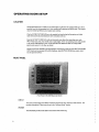
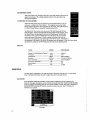
FRONT PANEL
‘ ‘Front Panel of the NIM-Response Monitor
lJlSPLAY
The touch screen displays both EMG waveforms and controls many functions of the monitor. The
complete description of these controls are in the "Software Setup” section.
SPEAKER
The SPEAKER provides audio alarms and acoustic EMG monitoring.
REAR PANEL
.-/
mifliiififliésgéinszaw
.-»_________~NNg,?'\-:5
hilt.
IIII I I I I I III:InIII
I-,1! II III“ I III‘:
‘Rug,I ]I;@I’ "'Il' fig?" ‘I lift‘
IIIIIII I I I I I . IIIIII I I I I I I IIIIIIIIIIII..iI
x,‘__._//
~
'
I" Q /-~-*’‘''
-«
-
—.I
I
,II”
/ft...._7,:..._.................-....._-......__...-............-..............._..........._-...._.._._.-........__..-.__........._,.§
\‘"''/
I.
..
‘ NIM~Response Rear Panel
LPT1 OUTPUT
The LPTI OUTPUT is a centronix type connector fora PRINTER, LS I 20, or Zip Drive.
2.
VGA OUTPUT_
A VGA OUTPUT is available through the standard VG/-\ 15 pin connector on the back panel. The
NIM-Response can be connected directly to a VGA monitor. The VGA Output can also be converted to S~VIDEO format for use with S—VIDEO VCR, the Landmarx Image Guided Surgeiy System,
or other S—VIDEO devices.
3;.)
FOOTSWITCH CONNECTOR (OPTIONAL)
The two pedal l"ootswitch adjusts the Stimulus up and down.
4.
MUTING PROBE INPUTS
There are four MUTING PROBE INPUTS on the NIM—Response Monitor. One MIJTING PROBE is
shipped with the system (8260000). Plug the MUTING PROBE into MUTING PROBE lNPU’I‘#-3.
5.
POWER CORD
The POWER CORD plugs into the back ofthe NIM—Response Monitor. Plug the POWER CORD
into the A/C power outlet.
6.
POWER SWITCH
The POWER SWITCH turns the power ON or OFF.
7.
FUSE ACCESS
Replace with Type F 250V fuses only. For l00- I 20V wall power, use 4.0A Fuses. For 220-240V wail
power, use 2.0 A Fuses.
8.
PATIENT INTERFACE CONNECTOR
The PATIENT INTERFACE CONNECTOR is a 25-pin D—sub connector which accepts the cable
fi'om the PATIENT INTERI-‘ACE BOX. Plug the PATIENT INTER FACE CABLE securely into the
back ofthe NIM-Response at the PATIENT‘ INTERFACE CONNECTOR and tighten the thumb
screws.
~
9.
LANGUAGE SWITCH
The LANGUAGE SWITCH is set to English by default. It may be switched to French, Italian,
German. or Spanish as needed.
I0. FACTORY I CUSTOM MODE SWITCH
The Factory/Custom mode switch allows the unit to be returned to original factory settings. To
reset the software to Factory mode, move the switch to “I-"‘ and then power the unit ON. The
normal mode is Custom (“C“) which allows the user to save Custom configurations.
I I. ACCESSORY POWER OUTLET
The Accessory Power Outlet powers pcrpipheral devices used with the_NlM-Response System.
THE PATIENT INTERFACE BOX
S"""‘“"”°”‘"“
Patient Interface Box and Cable'
The PATIENT INTERFACE BOX and CABLE. link thepatient to the NIM-Response.
ELECTRODE INPUTS.
Two electrodes per monitoring channel and one ground electrode are required. The positive (1') and
negative (-) electrodes for each channel plug into color coded input jacks on the PATIENT INTERFACE BOX. Channel I is blue; channel 2, red; channel 3, violet; channel 4, orange. Plug the
patient Ground into the green inputjack, and the anode for the probe into the red input jack of the
stimulate):
STIMULATOR OUTPUT
The NlM-Response System supports the use of two stimulation probes. Each stimulator requires
two leads. one from the probe and one from the patient, to provide a complete circuit. The lead from
the stitnulator is the cathode and is plugged into the black, negative (-)jack. The lead from the
patient is the anode and is plugged into the red, positive (+) jack. Plug the connections for the
stintulatot‘ probe into the STlMUI..A'l'OR OUTPU'l'jacl<s on the PATIENT INTERFACE BOX.
WN-
~, .
wt.
A WARNING
Do NOT TURN POWER To THE NIM-REsI>oNsE SYSTEM ON WHEN THE STIMULATOR Is IN THE FIELD.
UPON APPLICATION op POWER, A PULSE or 5 MA MAY BE DELIVERED FOR LESS THAN 0.01 S. THIS MAY
BE EXCESSIVE FOR some MONITORING APPLICATIONS.
STIMULATOR FUSE
Replace with Type F 32 mA 250V fuse only.
THE MUTING PROBE
A MUTING PROBE is connected around the output cable ofequipment, such as bipolar electrocaureiy, ultrasonic debulking devices, or other external devices which generate interfering signals.
Always attach the MUTING PROBE close to the otItpt:t_iacks ol‘tlIe electrosurgical or other uIIit
rather than near the handpiece the surgeon uses. More than one output "cable may be accommo.dated in the MUTING PROBE at one time.
To install the MUTING PROBE:
I.
gs)
3.
Open the MUTING PROBEjaws and insert the cable from the external device(s).
Slide the cable so the probe is near the main unit of the external device(s), not near the
l1andpiece(s).
'
Slip the upper side of the anti~slide ring around the end of the MUTING PROBE to form a “U”
around the cable. Pullit snugly agaiitst the probe‘s lower jaws.
MUTING PROBE INPUTS
There are four inputjacks for MUTING PROBE input. These four inputjacks are individually preset
to represent a giaduated muting gain. Input jack ii I is the least sensitive for Inutiiig, detection, while
iuputjack #4 is the most sensitive.
MUTING PROBE jack #3 provides the ‘‘typical_'’ gain value for the muting detection feature.
Should there be a need for more or less gain. depending upon the conditions of the operating room
setting or am ount of detection desired from a given electrosurgical unit, simply move the muting
. probe into a more appropriatejack.
’
A WARNING
AUDITORY AND VlSUAL MONITORING ARE DISABLED WHILE MUTING IS IN EFFECT.
SOFTWARE SETUP
The NlM-Response front panel features a screen which displays EMG waveforms. The NlMResponse is operated by using toucl1~sensitive areas of the display screen.
MONITORING SCREEN
'
»
,
The MONITORING SCREEN displays EMG waveforms.
A STIMULUS FILTER indicates where the STIMULUS
FILTER ends and real EMG data begins when using
either a monopolar or bipolar stimulator connected to the
NlM—Response.
The touch-sensitive areas ofthe screen provide information and control by toggling between settings or
displaying popup menus.
CHANNELS 1-4
..1__.|_4...__:_..__I___.i.
Event Threshold
Four channels can be monitored. During power-up, the NlM-RESPONSE automatically turns ON
each channel that has an electrode connected from the patient to the Patient interface. Pressing
the CHANNEL button toggles the corresponding channel ON or OFF.
TIME SCALE INDICATOR AND CONTROL
Time: 151! 510E
UBCIIODOG
0.00 mft Measured [
.
Pt:
I
Event Threshold.
The 50 ms TlM E SCALE is the Power Up default. The 50 ms TIME SCALE graphs a detailed view
of the data and is most‘ effectively used to view a captured event or the detail for baseline or nonstimulated activity. When EVENT CAPTURE is ON, the screen will display the detail of the last
«event captured until a new event occurs. when EVENT CAPTURE is Oi-T-‘., the screen displays a
slightly undulating line until an event over the threshold level occurs; then, that event appears
only briefly on the display.
.,_‘,
~;.,-
The 10 S TIMI": S(.‘.Al_.l‘;,'which resembles a histogram, graphs the ntaximum amplitude excursion of
the 50 ms TIME SCALE sample, not just events above the EVENT THRESHOLD setting. That is,
each vertical bar (one pixel coltnnn) in the i0 S TIME SCALE represents a sample which can be
expanded in the 50 mS TlM E SCALE.
.
The I0 S TlME SCA_l.l-I is useful for visualizing recent baseline EMG levels of‘ active channels and
the S'i'l M Marker to show Stimulus activity. When EVENT CAPTURE is ON and an event over the
threshold setting occurs, the Tone audio (if selected) will sound. The NlM—Response continues to
take readings and display the ongoing data in the l0 S TIME SCALE.
EVENT THRESHOLD
Any EMG activity thatexceeds the EVENT THRESHOLD is defined as an event. The event is heard
as a beep cal led an EVENT TON E. When EVENT CAPTURE is ON, these event waveforms are
displayed until replaced by the next event. The EVENT TH Rl-ISHOLD is adjustable from 20 pv to
2500 uv. The default EV].-ZNTTHRESHOLD is I00 pv.
Under certain circumstances, the default value of 100 },lV may not be significantly greater than the
baseline activity; therefore, it may be too sensitive. lnthis case, the EVENT THRESHOLD may be
adjusted to reflect a more appropriate setting.
To adjust the EVENT THRESHOLD setting, press the button indicating the present setting.
The setting will flash. The setting can then be adjusted by either touching the graphical scale or
touchingthe “+-"or "‘-" buttons . The new setting is indicated on the setting button while it is being
adjusted and is also indicated by the relative position ofa small vertical bar on the relative scale.
Event Threshold Setting Control
AUTO EVENT THRESHOLD
in a situation where the EMG has been elevated for a few seconds, the EV ENT TONES (beeps)
stop being helpful and simply become noise. The NIM-Response can automatically adjust the
EVENT THRESHOLD to maximize infonnation from the EMG andminimize unnecessary noise. The
EVENT Tl-IRESHOLD is a filter that brings more significant events to the surgeon's attention while
hearing the raw EMG from less important ones. The AUTO EV ENT THRESHOLD can help the
surgeon use the most sensitive settings possible.
The AUTO button is next to the EVENT Tl-IRESHOLD setting and has a square to indicate whether
it is selected. The default is OFF.
'
The EVENT THRESHOLD remains the same for all channels until part ofthe baseline ofan active
EMG channel increases above the EV ENT THRESHOLD forntore than 5- l 0 S ofnumerous event
tones sounding. When detected “BASELINE INCREASED” is announced the EVENT THRESHOLD ot‘ each effected channel is adjusted relative to it"s baseline, and the text “AUTO" flashes.
The AUTO EVENT THRESHOLD setting of each channel is displayed on the right hand side ofthe
screen. Raw EMG from each channel is still audible.
The lhresltold automatically tracks an increasing or decreasing baseline, announcing “BASEl-lNlE.
INCREASED" for each significant further increase. if the baseline value decreases, the auto
EVENT THRESHOLD resets at a lower value, until the setting reaches manual setting of the EVENT
‘THRESHOLD. At that time. “Baseline Decreased” is announced, the text “auto“ stops flashing.
MEASUREMENT CURSOR
1.... um 35
With Event Capture on, touchinga point ofa wave form causes a pop-upbox to
appear on the screen. The voltage antplitrrde and time from zero (known as
latency) are displayed.
,
‘
CALIBRATING THE TOUCH SCREEN
:
“"“‘
When the touch screen seems to respond in an unexpected manner, it may be
necessary to calibrate the Touch Screen. This happens because the Touch
Scr'een registers the press in the wrong place on the screen. Examples of this are
the Touch Screen failing to respond or responding erratically.
To calibrate the Touch screen, turn the power of the NlM Response OFF and
back ON again. when the Xomed NlM-Response Splash Screen appears, press
the Touch Screen until prompted to remove your finger; press Touch Screen
Calibration. Next, a prompt is displayed to touch the lower left comer and the
upper right corner of the screen. Finally, a prompt is displayed to touch the
center of a circle appearing in the ripper right corner of the screen. I f the touch is
not registered in the center ofthe circle. the sequence must be repeated- When the Tottch screen
completes the calibration, the NlM-Response enters its normal operating mode.
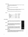
DEFAULTS
Setting __
. __:
Default
Other Options
Channel I-4 and Reference Channel.
Auto ..................... Manual
Time Scale ........................................... .. 5(TmS .................... .. l0 S
Vertical Scale ............................
500},tV ................... .. .?.00|J\/,2000}.lV
Stimulus
....................................... .. 0.00 mA .................. .. 0.0l'mA to 3.00mA
Event Threshold
lO0i.tV
20 i.tVto2500 t1V
Auto Event Threshold .......................... .. Off ............ ....... .. On
Event Capture
.................... On
Off
Volume .........................
50% ................ .. 0-l00%
MAIN MENU
The Main Menu is displayed on the right—hand side of the screen while the trnit is in monitoring
mode. The Main Menu allows the user to adjust many of the software features.
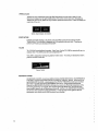
ELECTRODES
ELECTRODES displays the impedance of electrodes and difference of their impedances for
Channel I through 4 electrodes, as well as Ground and Anode electrodes. While the ELECTRODES
screen is displayed, monitoring does not occur and the speaker is muted. The words “WARNlNG!
MONITORING lS DISABLED” blink in reversed text to alert the user. Al'1'er' 30 Seconds, the
MUTING voice is heard.
Electrodes
cna («y
Ch
3(-)
Drllclencg
I ‘l chat-)
Cnfllei
I Relcrmoe
Drllnrutcn (4)
Relevance
Drllcrenc: (-)
1) p,:AI Electrode finfiflt 5:Channel Drllcreree
Sv:invrno‘E-’er.rrofl¢: <1D!(I7 CQKIY
Prat:Cn¢:'.w:l'.:al‘|uuc
Paved Electrode: Om
x‘£‘5>{f:
EMG
tom <5tfl'
«amI
imam.-e marinas: «nun <r;rm
Electrodes
'«-.
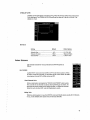
ELECTRODE PLACEMENT
ELECTRODE PLACEMENT displays the electrode placement to monitor cranial motor nerves by
touching the corresponding cranial nerve number. Monitoring continues in the background while
these menus are displayed.
Press the Cranial Nerve number and electrodes appear. The exact placement ofelectrodes is based
on the physician’s knowledge of the procedure and the'Cranial Nerves that are to be monitored
during the procedure.
‘
Electrode Placement
Red \'IllD Pall-CH2
RigntVncaiFaI:1
Rad VIIIB Pillr-CH7
Right Vueui Fold
’ PRINTISAVE
PRINT sends the screen displayed to the printer.
'
.
Ylmfl'1"°l’53
TOOLS button allows access to advanced features of the NlM-Response.
CUSTOMIZE MENU
CUSTOMIZE provides menus used to C0llfigl.ll‘C many ofthe ‘NlM-RESPONSE
features.
200
Sc 'v .
ru .
QUICK SETUP MENU
QUICK SETUP menu provides the ability to create and select surgeon or proce~
dure preferences for feature controls and settings.
E W“
4
QUICK HELP’
Afler selecting QUICK HELP, pressing any feature on the Main Monitoring Screen displays an
explanation of that feature.
-
>
T
TIME SCALE
TIME SCALE toggles between two different display time scales: 50 ins and lo S. Selection is
displayed on the right middle portion of the screen in the main menu.
VERTICAL SCALE
VERTICAL SCA LE selects the range ofthe EMG data display from 200, 500 or 2000 ttV scale.
Selection is displayed on the right-middle portion of the screen in the main menu. Changing the
VERTICAL SCALE only affects the way the data is presented on the screen. lt does not modify the
sensitivity of the unit.
Verticle Scale Indicator and Control
EVENT CAPTURE
EVENT CAPTURE displays on the 50 m5 screen any EMG activity that exceeds the EVENT
THRESHOLD. This waveform is displayed until ‘it is replaced by the next event. Touching the
EVENT CAPTURE turns this feature ON and OFP.
VOLUME
The VOLUME control adjusts the speaker. Upon Power Up, the VOLUME is automatically set at a
. moderate level. VOLUME cannot be turned completely OFF.
VOLUME is adjusted by touching the graphical volume scale. The setting is indicated by relative
position ofa small vertical bar.
'
Volume Control
REFERENCE CHANNEL
REFERENCE CHANNI.-‘.I.. is used as an additional means ofartifact determination. The REFERENCE
CHANNEL compares active EMG channels to a neutral or “reference” channel. When activity on
the REFERENCE CHANNEL is detected greater than EVENT THRESHOLD at the same time there
are Events on an EMG channel the “REFERENCE ACTIVITY" is detected and is announced.
Place the two REFERENCE CHANNEL electrodes in a muscle not affected by manipulation ofthe
nerve being monitored. For example, when monitoring the right facial nerve, the reference elec~
trodes could be placed in the lelt obicularus oris muscle. Activity on the REFERENCE CHANNEL
may be from other equipment causing interference. it may also may be from global evoked or
spontaneous neuro motor activity like the patient becoming light. 7
10
C..
QUICK SETUP MENU
,
Quick Setup Menu provides access to configuration of features. The settings
configurations can be modified in the following ways: SELECT, UPDATE,
ADD". and REMOVE.
.
»
SELECT
Quick Setup configurations can be chosen by pressing SlSl..l£C'l". A list of
stored settings is displayed. Press the configuration and then press SELECT.
The active Quick Setup configuration is displayed on the SELECT button of the
Quick Setup Menu.
UPDATE
To UPDATE an existing configuratioit, verify the configuration that isactive (which is displayed on
the SELECT button ofthe Quick Setup Menu). Adjust feature settings such as Stimulation, Event
Threshold, Event Capture and then press UPDATE. This saves these settings oi‘ this Quick Setup
configuration.
:‘uIi
EEEJE
_‘J
ADD
To ADD configurations prei’cn'ed by the surgeon, adjust feature settings such as Stimulation,
Event Threshold, Event Capture and then press ADD on the Quick Setup Menu. A keyboard is
displayed to allow the entry of the name of the physician or the procedure conl‘1gurations. Press _ '
Accept to save these settings under the name that was typed. Pressing .“X" exits this interface
without saving.
REMOVE
_ Quick Setup configurations can be deleted by pressing REMOVE. A list ofstorccl settings are
displayed. Select the setting to be removed and then press REMOVE.
11
CUSTOMIZE MENU
CUSTOMIZE is used for modifications to the listed features. The NlM~Response continues monitoring while settings on the configuration menus are
being changed.
STIMULUS
The STIMULUS appears at the top left corner ofthe display and controls the
stimulating current delivered by stimulator probes when connected to the NlMResponse. 'l‘he_range of output is 0.0 to 3.0 mA. While below 0. I 0 mA the
setting is adjustable by increments ol‘0.0l mA‘; while above 0. I 0 mA, it is
adjustable by 0.03 in/\. The default STIMULUS setting is 0.00 mA.
4
Rzscatch Ycola
0.00m/‘A I.".CBSutE:l|
Stimulus
l
Exit.
I
Stimulus Setting Control
To adjust the STIMULUS intensity, press the setting button. You see the setting flash. 'l‘he
setting can then be adjusted by either touching the graphical scale or touching the “+" or
“~” buttons. The new setting is indicated on the setting button while it is being adjusted and is also
indicated by the relative position of a small vertical bar on the relative scale.
The MEASURED value, which appears in the top right corner of the display screen, reflects the
amount ofstimulating current “flowing through the patient" and should approximate the
STIMULUS value is displayed in milliamps (mA). The MEASURED value may fluctuate between
0.00 mA — 0.05 mA until contact is made by a probe.
Stimulus _Submenu
STIMULUS RATE
fittmutus
The rate of stimulation is adjustable. The stimulus pulse can be delivered at a
rate ofeither l/S. 4/S, 7/S, or l0/S. The default rate is4/S.
snuutus DURATION
I . to/so
The duration of stimulation is adjustable. The stimulus pulse lasts either 50
pS, I00 us, or 250 us. The defaultduration is I00 I13.
DURATION
_I
I
1OOuS
6)
?.50L\3
O
Stimulus Filter
v-.
m<~a.-«
12
STIMULUS FILTER
STIMULUS FI LTIE-LR displays a window showing where the stimulus artifact delay ends and real
EMG data begins. The STIMULUS FILTER can be set for values of: l.00 ms, to 4. I0 ms. The
default is 3. I0 ms.
~
DEFAULTS
Setting
Default
I Other Options
Stimulus Rate ............. .f......................... .. 4/S ........................ I/S. 7./S, l0/S
Stimulus Duration ............................... .. l00uS .................... .. 50pS and 250|.1S
Stimulus Filter .................................... ..3.l0mS
............... .. l.00to4.l0mS
Voices Submenu
The VOICES controls the voices produced by the NlM-Response as
follows:
.
Elflcllbflfl G)
HELP VOICES
MW
Audible HELP voices can be turned ON or OFF via the Voices submenu. when
the HELP voices are turned ON, you can_ select specific voices. When the HELP
voices option is turned OFF. all help voices are OFF.
'
Check Electrode Voice
When an electrode is not detected, the “CHECK ELECTRODE” alarm sounds.
This could be due to electrode not placed, electrode falling out of patient, the
electrode not properly seated in the Patient Interface, or a defective electrode.
When this voice is turned OFF, only the Bleedle alarm sounds.
Mating‘ Voice
While the electrocautery is in use, the M UTING voice and Bleedle alarm sounds after 30 Seconds
of use, and the Bleedlc alarm repeats every 30 Seconds thereafter.
13
STIMULUS VOICES
STIMULUS VOICES can be configured as SETTING, “STI MULUS," TONE, or OFF. The default is
STIMULUS VOICE set to ON and SETTING selected.
Stimulus Voice
The stimulus voice verifies delivery ofcurrent to the surgical field.
Setting Voice
The SETTING VOICE announces the value ofthe STIMULUS. It also announces the new stimulus
setting when it is adjusted. Example: 0.50 mA is announced as “Point Five”.
Tone
Stimulus delivered through the probe to the surgical field is confirmed by a tone.
DEFAULTS
Setting
Del}! tilt
Other Options
Helpvoices ............................................ .. On ..... .. . ........ .. Oii‘
Check Electrode ............................. .. On . . . . . .
. .. .. Ofl’
Muting .................................................. .. On .... ..
Stimulus Voices ..
Setting
Stimulus .............. ..
Tone ..................... ..
'
'
Volume .................................................. .. 20°/6_ .............. .. I0-l00%
Ton es Submenu
The TONES submenu controls the raw audio and tones produced by the NIM~
Response. The EMG Audio and EMG Tones cannot be turned OFF simultaneously.
EMG AUDIO
The EMG Audio can be turned ON orOl-‘F. When it is ON, EMG activity can
be heard ‘as a static-like grinding sound. The volume can be turned up or down
using the Volume Control keys. When it is OFF, the EMG audio cannot be
heard. The default setting is EMG audio on.
EVENT TONES
The Event Tones can be turned ON or OFF. when it is ON, an EMG event
above the set EVENT THRESHOLD is heard as a beep tone. The tone reflects
on which channel the event occurred. A lower pitched beep represents ' '
Channel I; a higher pitched beep represents Channel 2, and so on through
Channel 4.
'
STIMULUS WARBLE TONES
The STIMULUS WARB LE TONE sounds whenever electrical current is being delivered to the
_ surgical field, through the stimulus probe that is greater than 80% of the set current. The current
delivered TONE or VOICE is not active below .05 mA. The duration of the STIMULUS TONIZ is
~. .
adjustable as follows: OFF, BRIEF, CONTINUOUS, OR VOICE.
R.».—
14
TONE VOLUME
May be set by touching along the graphical volume control bar, with FULL volume to the far right.
Volume Control For Event Tones
DEFAULTS
Set£iM|_i£_
Default
EMG Audio
EMG Tones
Stimulus ....... ..
Tone Volume ......................................... ..
On . . . . . .
. . . ..
On .. . . . .
. . . ..
Brief . ... .
. .. ..
0.30 ...................... ..
Other Options
Off
Ofl‘
Continuous,Voice
0. l0— l.00
Clock Submenu
The CLOCK submenu allows the correct time and date to be entered into the.NlM-Response. Time
is displayed in 12 hour and 24 hour l‘ormals. The date format is U.S. (mo/day/yr) or CO (day/mo/yr)
with leap year compensation valid up to 2100.
Inna Formal
mil PM
Dale FormaL
Clock Adjustment Window
15
Research Tools Submenu
Output
OUTPUT MENU
The Output Menu is used to select whether inl"ormation is documented to a
@
HPGL compatible printer, L8 1 20 SuperDisk drive, or a ZIP drive. The
Event Ca PM 3
information is formatted according to Output. Menu selections are sent to
the Pitin teriData Output on the back panel of‘ the NIM-RESPONSE.
EVENT CAPTURE
’
_
Largest
O
When the EVENT CAP'l‘URl3 button on the Main Menu is ON, it holds
V
each Event on the screen until it is replaced by the next Event. when
F F9628
EVENT CAPTURE is OFF,the current EMG activity waveform is displayed.
LARGEST
'
LARGEST displays each EVENT as it occurs and at the end ofa series of‘ ’
events, displays the LARGEST of these waveforms. The screen continues
to display each EVENT and holds the LARGEST at the end ofthe series of‘
Events.
.
0
El
Channel tome
FREEZE
When Freeze button on the Main Menu is turned ON, it will hold the
‘
waveform until Freeze is turned OFF. When Freeze is OFF, the current EMG activity waveform is
displayed.
CHANNEL MUTE
Wlien channel mute is selected, a speaker icon appeals with each selected channel. Pressing the
channel select button cycles through channel on, channel mute (speaker icon blank), and channel
off.
OUTPUT
DEVICE
;
when Printer is selected, the ‘‘Print’‘ button is displayed on the main menu.
The default device is Printer.
When either the LS l20 or the ZIP is selected, the “Print” button becomes
“SAVE IMAGE” or “SAVE DATA“. depending on the format selection. when
the unit is in the process ofsaving, the button will display either "SAVlNG
lMAGE" or “SAVING DATA.”
Save
Image 0
Ffle Lpcx)
Save
Data 0
File(.txt)
3
File Format
LS12O
FORMAT
ZIP
0
The FORMAT ofittfortnation saved to disk can be either an‘lMAGE file or a DATA
LOG. The IMAGE file is stored in PCX format. The DATA LOG file contains the
time and X and Y data in an ASCl| comma delimited format. The default FORMAT
v islMAGE.
DEFAULTS
Other Options
Output Device .................................... .. Printer .................... .. LS I20, Zip
View ............................ ..
.l3vent Capture ..
.... .. Largest, Freeze
MeasurementCursor....
. ......Ot’f ........ ..
Channel Mute ....................................... ..Ofl‘ ........................ On
17
2 0 USING THE NIM-RESPONSE
ANESTHESIA REQUIREMENTS
All decisions regarding anesthesia are the responsibility of the attending licensed medical practitioner administering the ancsthesia. Because all intraoperative monitoring discussed in this User’s
Guide requires that EMG activity be recorded from a muscle or muscles, it is important that the
muscle(s) not be paralyzed during the surgery or at least during those parts of the surgery when
the nerve(s) being monitored is (are) deemed at risk by the surgeon. lt is important that the surgeon
discuss these issues preoperatively with the attending licensed medical practitioner administering
the anesthesia.
A WARNING
THE use or PARALYZlNG ANESTHETIC AGENTS WILL SIGNlFlCANTLY REDUCE, IF NOT COMPLETELY ELIMINATE, EMG RESPONSES TO DIRECT on PASSIVE NEURAL STIMULATION.
ELECTRODE SELECTION
When selecting recording electrodes, the following questions should be considered:
- What muscle group (5) is (are) being monitored?
- l-low will the electrodes be secured?
- ls subdermal or intramuscular placement more appropriate‘?
There are several electrode styles available for monitoring electromyograpliy. You may need to try
different types to determine a preference.
ELECTRODE PLACEMENT
F.lectrode placement should be performed by or under the direction of a licensed medical practitioner. Areas of electrode insertion should be prepped by vigorous cleaning with an alcohol wipe.
Usually, recording electrodes are placed before the sterile field is draped and defined. Never let
electrode leads contact one another.
The exact location for the electrodes is defined relative to the surgical procedure being monitored.
For all facial nerve monitoring, the patient ground electrode may be located on the patient’s upper
chest (sternuin). The placement for the anode (-4-) electrode for the inonopolar stimulating probe is
on the ipsilateral shoulder.
Once the electrodes have been placed and secured v_vith tape, the connector end may be inserted
into the inputjacks on the PATIENT lN'l‘l3Rl'-‘ACl3 BOX.
'
-la.»
A WARNING
TO AVOID EYE INJURY DURING ELECTRODE PLACEMENT, THE ELECTRODE NEEDLES SHOULD BE DIRECTED
AWAY FROM THE ORBIT WHEN INSERTED FOR ORBICULARIS OCULI MONlTOR|NG.
-. .
18
._ w’
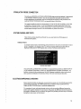
STIIVIULATOR PROBE CONNECTION
The cable on a MONOPOLAR STIMULATOR PROBE plugs into the black cathode (—) stimulusjack
on the PATIENT INTERFACE BOX. Since the stimulator probe and cable must be sterile "for
surgical applications, the stimulator may be connected at the beginning of the procedure in the
event the PATIENT INTERFACE BOX is not accessible later on in the case.
The surgeon should test probe for current delivery as soon into the case as possible. This is done
by selecting a “stimulus intensity” on the NIM-Response front panel (greater than 0.00 mA) as
indicated on the STIMULUS mA portion of the screen. An intact circuit results in corresponding
numbers approximating set amount in the MEASU RED mA portion of the screen. -
SYSTEM CHECKS_AND TESTS
These checks and tests should he performed for every case before the NIM-Response is
connected to the patient.
POWER UP TESTS
An internal integrity check is automatically performed each time the system is turned ON. You see a
series of messages on the display screen. The software version number and revision date are
displayed briefly, then the NIM-Response does a series of self-tests on the hardware.
"
were
.
Master Processor Program ..
Master Processor RAM
Touch Controller Program.
Touch Controller RAM ..... ..
Slave Processor RAM ..................... ..
Slave Processor EPROM ................. ..
System Watchdog Timer ..
‘
System Parameter RAM ........ ........ .. Pass
Hardware Test Results
Ifany self test fails, call MEDTRON IC XOM ED U.S. Customer Service toll-free at l-800-874-5797. If
you are outside the United States, contact your local MEDTRONIC XOM ED representative. If a
problem is found with the microprocessor, the NlM—Response immediately returns to the second
start up screen and indicate a microprocessor failure. No more monitoring can take place.
ELECTRODE IMPEDANCE CHECKING
Ensure that all electrodes are adequately connected to the patient and to the NIM-Response before
surgical drapes are in place. The NIM-Response has an impedance meter to perform this test.
Display the ELECTRODES screen to access the impedance rest.
The impedance for each individual electrode is shown with the resulting difference between the
positive and negative electrodes for each channel. The greater the difference between the positive
and negative electrodes on any one channel, the greater the possibility that there may be unwanted
background noise present on that channel.
19
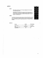
Typical impedance values are as follows:
-
Prass Paired EMG Electrodes
Subdermal needle electrodes .... ..I ........ ..
I-lookwire electrodes ..................... ..
Endotiacheal . . . . . . . . . . .. . . . . .
. .. ..
Paired subdernial .... ..
25 kt) or less
I0 k9. or less
40 kt) or less
l0 RQ or less
20 kt) or less
The difference in impedance between the positive (+) and negative (—) of a channel should be less
than I0 - 20% of the lowest channel impedance. Press the “x” in the upper-right hand corner to
return to the monitoring screen.
QUICK SETUP
At power-up. QUICK SETUP settings are displayed along with the statement, “Select Physician
Initial Settings”. These settings may need to be adjusted as the surgery progresses. Any of the
saved Physician Settings may be selected,’ however if no selection is made within I0 Seconds, the
settings of the highlighted names are activated. The main monitoring screen is then displayed.
Verify that the STIMULUS and EVENT Tl-IRE-ZSI-IOI..D values the physician desires are set.
CHECK ELECTRODE ALERT
During power-up, the NIM-Response automatically turns ON each channel that has an electrode
connected from the patient to the PATIENT INTERFACE BOX. When no electrodes are plugged
into the I’A'l"lF.NT INTERFACE BOX, the NI M-Response warns you in 20 S that an electrode lead is
not making proper electrical contact (OFF). You then hear the Bleedle Alarm. 1‘he channel button
flashes continuously until the electrode is placed or the channel is turned OFF. The electrodes
screen is displayed showing which electrodes are OH’.
The NlM-Respo_ns'e checks all the electrode leads every I/2 S during MU'l'lNG and El..EC'l'RODl3S
CHECK by sending 60Hz pulses through the leads. It reads the impedance of each lead and verifies
that the readings are within normal range.
When the electrode impedance levels are too high. MUTING turns on and the “CHECK ELECTRODES” Bleedle Alarm sounds. The indicator light of the affected channel flashes. The ELECTRODES screen is displayed and indicates which electrodes are outside of normal operating range
or“OFF”.
MUTING ALERT
When the NIM-Response stays in Mute mode for more than 60 S (except during an ELECTRODES
CHECK), the MUTING alarm sounds to warn that there is no ongoing acoustic or visual monitoring. The message “WA RNING: MONITORING IS DISABLED” flashes on the screen. Alarms repeat
every 60 S until the NIM-Response exits Mute mode.
ADJUSTING THE EVENT THRESHOLD
BASELINE ACTIVITY
Typically, when the nerve to be monitored is not being electrically
stimulated or manipulated by the surgeon, there is little or no EMG
activity tletected. Therefore, the magnitude of the on-going ‘quiet
baseline’ signals may be quite small. These signals may be 30 l.lV
or less and are shown on the left side of the screen near the
appropriate channel microvolts (_uV) only when Event Capttne is
Off. If Event Capture is On, the microvolts (tr V) will reflect the
amplitude of‘ the last event on the channel (s) being monitored.
Peak-to-Peak Voltage Reading
20
SETTING THE STIMULUS LEVEL
Press the STIMULUS setting button in the upper left corner to adjust the stimulus output to the
desired level. The stimulation level is displayed on the button.
Stimulus Control and Indicator
At present, there is no complete agreement on the optimal level for facial nerve stimulation (Beck
and Benecke, l 990). The absolrrte stimultrs intensity required to adequately stimulate any cranial motor
nerve is detenniued by a complex combination ofseveral factors including _(but not limited to) the following:
- The Functional health ofthe nerve itself
The type of stimulation probe used (monopolar or bipolar)
How well the stimulator probe makes contact with the nerve
Whether cerebral spinal fluid is covering the nerve, etc.
i The duration of the stimulus
You may want to use the smallest amount of stimulus necessary to elicit a detectable EMG event.
Typically, stimulus current levels ol’0.3 mA are high enough for adequate direct monopolar
stimulation ofthe facial nerve. The best guideline for setting the stimulus intensity level is to use_
the lowest. amount of stimulation that produces an EMG response large enough for nronitoring.
WHEN ELECTROCAUTERY AND CUSA ARE USED
When the electrocautery is in use, the NlM-Response rnutes. After 60 seconds of muting due to
electrocautery, you hear “M UTlNG"and “WARNING: MONlTORlNG lS DISABLED” is displayed.
The blcedle alarm sounds every 60 seconds.
Whenever electrocautery is in use" or is in the standby mode, the electrocautery tip should be
isolated l"rom the NIM-Response stimulator probe and electrodes.
When CUSA (cavitr-on (ic) ultrasonic aspirator) is in use, effective monitoring cannot take place.
The baseline may rise on one or both channels to 200-500 _uV. You may compensate by adjusting
the Event Threshold up and then down after the CUSA is off. The baseline may still linger at 40-80
uV. However, an increase in the baseline right after use of‘CUSA may indicate nerve irritation.
Another example of when prolonged muting might occur is when a radio~l'requency signal of
unknown origin occurs in the surgical environment without the knowledge of‘ the surgical team.
‘UNDERSTANDING WHAT YOU HEAR
EMG ACTIVITY
The TONE MENU is used to select whether BMG AUDlO, EVENT TONES, or both are audible.
Both EVENT TONES and EMG AUDIO can be ON at the same time, but both features cannot be
simultaneously disabled.
The EMG AUDIO signals are not influenced by the EVENT Tl-IRESHOLD. Therefore, all EMG
activity, regardless ofamplitude, is audible when the EMG AUDIO is ON. The EMG activity may
sound like a low-pitched clrumbeat at times. When two channels are monitored at the same time, it
is unlikely that you will be able to differentiate the EMG signals as to their channel oforigin strictly
by the sounds they produce.
EVENT TONI-ZS, however, is coded to distinguish the channel of origin. Only signals with amplitudes exceeding the EVENT THRESHOLD produce a tone.
The tone for Channel l activity is lower in pitch than the Channel 2 tone and so on for channels 3
and 4. This lets you tell by the tones pitch which channel is involved. when EMG activity
exceeding the event threshold occurs at the satire time on both channels, only one of the tones
sounds.
VERIFYING STIMULUS DELIVERY
.
,
The NIM-Response allows you to verify delivery of current both audiblyand visually.
There may be times when the surgeon has placed the probe into the surgical field expecting an
I."-ZMG response and none is evoked. When this occurs and the nerve has functional intergrity and
was properly stimulated, you must check that a stimulus current‘ was actually delivered to the field.
One of the features ofthe NIM-Response is the STIMULUS Tone option which is selected from the
TONES MENU. When stimulus is delivered but no events are evoked, the STIMULUS WARBLE
TONE indicates that current has been delivered to the surgical site. EVENT TONES override
STIMULUS TONES. This can be set to BRIEF, CONTINUOUS, VOICE, or OFF.
Stimulus delivery can be visually confirmed by comparing the STIMULUS and the MEASURED
readings. The MEASURED reading is found on the upper right-hand side of the screen next to
STIMULUS. The value should be approximately the same as the STIMULUS SE'l“l‘ING.
RECOGNIZING ARTIFACT
The NIM-Response features sophisticated artifact rejection technology designed to provide
highly sensitive and accurate monitoring; The technology encompasses electtocautery detection,
overload detection, and stimulus artifact rejection associated with the stimulating MQNOPOLAR
probes. The signals associated with these conditions are automatically routed and will not be
heard.
However‘, there may be electrically generated signals in the range of true responses that cannot be
differentiated by the NIM-Response. For example, a transcutaneous stimulator used by the
'
anesthesiologist might generate an audible signal. Another example would be any external nerve
locator/stimulator not synchronized with the NIM-Response. Another possible source of electrical
signal is electrical leakage from faulty thermal cautery units. You can identify the spurious signals
by their lack of surgical context. That is to say, there was nothing the surgeon was doing at that
moment that could have. caused a true EMG response.
Another artifact signal that can be erroneously interpreted by the NIM-Response as an EMG event
cart occur when the surgeon strikes two metal instruments together within the surgical field, such
as striking a metal suction tube with a dissecting tool. Such signals are typically rnonophasic with
fast onset and offset. That is, the signals appear on the screen as sharply peaked responses in one
direction only.
While these artifacts are significantly different in waveform appearance from true EMG events
(which have a biphasic waveform), the magnitudes of these signals can reach several hundred
microvolts, exceeding the EVIL-'.N'l"l‘l-lRESl~IOLD. Therefore, this can cause the EVENT TONE to
sound. This type of artifact cannot be automatically detected and ignored by the NIM-Response.
However, the surgeon is usually aware when two instruments have been struck together and can,
therefore, relate such “false positive" responses to the surgical context. ’
A22
INTERPRETING THE ALARMS
The alarms draw attention to any condition which prevents proper data acquisition. None of the
audible alarms should be ignored. One must assume that valid monitoring has been halted, and
determine iininecliately why the alarm sounded. There are three distinct alarms:
BEEP ALARM
The high-pitched, repetitive beep is used to register failure of‘ internal.microprocessor hardware.
When yoti hear it at any time other titan at Power Up, stop using the NlM-Response System and
contact M EDTRONlC XOMED Customer Service at l~800—874-5797.
BLEEDLE ALARM
’
This is a three-note alarm (BLEE-dle DEET) that cannot be disabled. it repeats until the responsible
condition is remedied. This alarm is heard when:
-
A recording electrode lead is off (repeats every 20 Seconds).
The NlM-Response System has been in MUTE mode for more than one minute (unless you are
in ELECTRODE CHECK). Repeats about once per ininute.
VOICE ALARM
'
Severalcontext specific voice alarms are available. A relevant message is simultaneously _displayed.
WHEN THE CASE lS COMPLETE
Before closing the surgical site, the surgeon should evaluate the nerve’s functional integrity one
more time. This should be done by stimulating the nerve both proximal and distal to the immediate
dissection area as far as is accessible within the surgical field. Use the lowest level of stimulation
that produces a response.
Continue to monitor with the NlM~Response System throughout the procedure (until the incision
is closed),-since items such as wound dressings might exert stress or pressure on the nerve and
affect its function.
’
WHEN MONITORING IS SCOMPLETE
Turn OFF the power to the NIM-Response System when the entire procedure is completed, and
have the Licensed Medical Practitioner remove the electrodes from the patient.
The disposable Prass Monopolar Stimulator Probe and patient electrodes must be discarded after
surgery.
Wipe the PATlENT INTERFACE CABLE and the MUTING PROBE CABLE, and visually inspect
them for cracks and other damage. If they are damaged, return them for service.
23
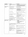
3 - TROUBLESHOOTING
lSYMPTOM
__
l
l CAUSE
] soLu'rioi~T—
l
l No visual display or atidio
l
alarms at ])()\\-‘Cr-ll|).,
l
Power cord not connected to outlet or to the
NIM-Rcspoiiae system.
,
l
«
;
Plug in power cord.
.
I,
l’ott-er stvttclt not turned oit.
_
I 1ui-n power sit-itcli on.
'l'oticliing the screen changes 4'l‘oucli screeii out tifcalibmtioii.
’l‘urn tiitit off, then press the screen tiiitil the screen
screen to recalibrate.
hasunexpectedresults. I l';Iectrode
V dislodged froiii patient. but not lI calliisertibradislodged
titin test iselectrode:
displayed.tapeFoldowiilowthineiplace.nstructionsonthe 4!
l Electrode itnpcdance is too
I high.
eotnpletely out.
electrodes
II >lOKQ
for subdermal '
>2SKQ for Press Paired
'
High rcsistatiee in electrode.
l
l
electrodes
>l0l(£2 for l3iVlG Tltbc
>-1 OKQ l‘or hooktvire
electrodes
.
I
Electrode pin not lirinl_v inserted into patient
intcilacc.
""j_j"".""‘"""""""’}""""‘
[Electrode impedance!)
t
Check eoiincciitin at Patient lntcrl‘ace box.
'
""~"“
E Positive and negative electrodes toticliiitg
I 0.0l\w.
Rcinuve and replace with new L‘.l€l3ll'0(lC.
E
I
""*”"”“
Remove and ielocute electrodes.
l
! below surface in skin.
I
I
Use "tap test" near electrodes to evoke li-ZMG or artit‘act. ll‘ ]
I-lxti'cincl,v l0\\-' iinpcclaitce. pat'tictilarly in
I l’-JMG tubes.
1 activit_v is noted on cliaiincl in question, proceed.
Cltaniielbtitton is llasliing. - l II-Llectrotle la_\-"in-__i on skin surface.
'
Re-inserteleetrodein qucstioii.
lilectrode reading is "--~ KS2" l.-Electrode plttecineiit insectire.
or “Ol-‘F."
Remove and replace electrode in question.
Dirty electrode tip.
l3Ieclt‘odc cable broken.
I’.-Zlectrotle pin disconnected from patient
Check connection to Patient liitcrt‘acc box.
i ntei-face.
I
Rcinove and replace electrode for appropriate cltaiinel with '
Elcctrotlc dillciciice is greater Dirty electrode.
than 2K§2 (stibtlernial'
Misinatcliccl pair.
electrodes) or IOKS2 ( Prass
higliest impedance reading lirst.
Unequal placement.
i Paired clectmtles).
I--—————--—»—-~
Electrustirgical iiitcrfereiice.
I Remove and replace electrode in question.
I
l
lI
————————-—
————?————————--I
Cltcck Mating Probe connections.
Mating Probe not connected.
Mating Probe input ii-.stil‘t'iciciit.
Ell;.‘ClI‘()SuI'glCal gtouiitliiig. inadequate.
Source ol'intci'l‘erenee tinidenti lied.
Move input to "MORE MU‘l‘l.’."“.
Check elcctrosiirgical giotiiitliiig pad on patient
Identify source of iiitct*l‘ei'eiicc: then eliminate or separate
l"i'om the NIM-Response system.
NIM-Respoitse s_vstein or Patient lnterl‘uee
cable too close to 133 U or its cables.
.___,,.___._
..,..._.,___.
liiterl‘erciice on anestliesia
eqtiiptticnt.
l?.xeessive itiuting.
Maintain separation bcttreen eleeti'ostii'gical cable and the
Nllvl-Response S)"Sl¢ll‘l.
'
For less coupling. coil tip the Mining Probe nest to the
NIM-Response system.
-.__w,......._..~-____._...._.._..__._.._.
_._.._..
I
I
.
.
Lead checking cttrrcnt near anesthesia
electrodes.
Unit receiving excessive signal into the
Mining Probe or electrode leads.
I
.
.
.
Anestliesia try alternate e Iectrodc channel.
Turn stintiilator to 0.0m/\ \\"lICl'l not stimulating.
. _j
: Move the Mating Probe connector to a lower iitiniher unit
until it stops mtttiiig. ll‘it still mules in positioii “l."
clisconiiect the muting detector cotiiplclely.
ij_
24
.
SOLUTION
Inadequate muting.
Signal from I-ZSU is inadequate to cause
muting.
Move the Mutiug Probe connector to a higher number until it
mules ll‘it still does not mute in position ''4.’' loop the ESU
cable and clip the muting detector over the doubled cable.
Inadequate stintttltts intensity.
Increase stimulus intensity.
l’at'al_\-zittg anesthetic in use.
Eliminate paralyzing anesthetic.
l
No
response to direct
stimulation.
I
!
l
l White stimulation l'+) electrode have fallen
l out or is not connected.
i[
I
Check that Stimulus Measutc is approxhnately the same Vfllllc
as tlte Stimulus setting.
Re-iusen electrode in question.
Secnn.‘ all recording and stintulating electrode eonnectionsand
check the impedance values.
Probe not connected.
Cheek stimulator anode (+) and cathode (-) connections.
‘alien! safely fuse blown.
Check litse in Patient lntcrl2':cc box (32 um. x 250V). Replace
il‘necessat3'.
Not holding probe on nerve long enough.
I-lold probe tip to nerve for at least i
Nerve. not cotttttcted.
Check stimulator tip for obstruction. Replace ifttecessat)-'.
Check location uf,stimulatiou.
l
Voluute control too low.
l
l Event threshold set too high.
l
Excessive current slnnttin_t_z in surgical field. .
Check and mnect all settitit_-_s: volntne. event tlnesltuld.
stimulus intensity.
Rentovclluitlsfi'otttsurgicalstimulatingarca.
No electrodes in innervated muscle.
Nerve not stimulnltle.
l Unexpected responses when
not (lit‘cctl_v stimulating
nerve.
Place channel electrodes in muscle to betnouitotetl.
l
l
i
i
Unexplained continuous "train“ ISMG
response.
I
l
I
identify and elintinate possible source ul“'train" stitnttlationz
Cold inigation
Laserhcat
Rl‘.ll'aCli()ll on nerve orntuselcs being recorded.
’aticnt waking frotn nncstltesia
Nctvedrvittg
Ultmsonic aspirator
l
l Nerve or ntonitoring area being stimulated
or manipulated by thcnnal or mechanical
means.
§
-identify and eliminate source ojinatlvenent manipulation.
l
Mctal—to-metal discharge artifact.
I lntertu-‘ined recordingelectrodeand
stbnulator wires.
Determine response type l‘rorn wavefonn pattern on 50 ms
. I screen.
I Disetttattgle recording electrode and stltnulatot-cables.
1
lnttdvertent manipulation ofelectrodc
wires. Patient Interface cable, or recording
1 areaonpatiet t.
I
Check area ncartecording electrodes l‘orexccssi\-'e sttetching
liom utpe. drapes etc.
l
l.'-Jlectrical interference l'rotn other
Check for intennittent stimulation from auestliesiolngjst (i.e..
hand-held electrical stimulator).
equipment.
I
l
Move NIM-Response s)stcm away liom source of
inter-tetettce.
Make sine Patient interface cable and elccttode tvites do not
Lw
. _.,
cmss otherelectrical equipment orealtles.
l
25
4 0 MAINTENANCE AND SERVICE
This section of the Uscr’s Guide describes how to care for your NIM-Response and what to do
when you have problems. Preventive maintenance does not require access to the interior ofthe
instrument and may be pert‘onned by the teclmician/operator.
For the safe and warranted use of the unit. corrective maintenance and intemal adjustments should
be left to qualified MEDTRONIC XOMED service personnel.
PREVENTIVE AND CORRECTIVE MAINTENANCE
Preventive maintenance for the NlM—Response System consists of visual inspection, periodic
cleaning and running a general checkout using the PATIENT SIMULATOR.
Follow the preventive maintenance schedule outlined below. Your own schedule may vary fi'otn this
schedule based upon the type and amount of system use.
CLEANING THE NIM-RESPONSE SYSTEM
Remove dust on the outside of the instrument with a soft brush or cloth. Remove any remaining
debris with a soft cloth that has been slightly dampened with alcohol.
VISUAL INSPECTION
Check the NIM-Response System occasionally for exterior damage. Only qualified MEDTRONIC
XOM ED service personnel should replace damaged parts.
'
AFTER EACH USE
Wipe the PATIENT INTERFACE CABLE, M UTING PROBE CABLE (S), and N I M-Response clean,
and visually inspect for any damage.
Clean any substance from the PA'I‘lEN'l' INTERFACE BOX, making sure that nothing is forced intothe electrode connector sockets.
SERVICE AND REPAIR PROCEDURES
MEDTRONIC XOMED is committed to provide the highest standard of workmanship in manufacturing the NIM-Response System. YourNlM—Response requires a minimal amount of maintenance:
however. MEDTRON IC XOMED recommends preventive maintenance and calibration scheduled at
yearly intervals. The Mainframe Biomedical Verification Test Procedures should be performed at
least annually and whenever a problem is suspected.
Comprehensive testing and calibration should be performed by returning the, entire system,
including the patient interface and muting probe to:
Medtronic Xomed Repair Department
6743 Southpoint Drive N
Jacksonville. Fl 322i 6
IF YOU SUSPECT A PROBLEM WITH THE NIM-RESPONSE
NOTE: When contacting our Customer Service and Technical Support, please have the
appropriate product number, product serial number, date of purchase and nature of inquiry
available.
ProductNutnbet‘ ..._.:.—.___..._._—_..__._.__—..
Serial Number
Date of Purchase
26'
-. .
A system that is not functioning properly SHOULD NOT BE USED AT ALL until all necessary
repairs have been made and the unit has been tested to ensure that it is functioning in accordance
with published MEDTRONIC XOMED specifications.
To avoid negating the warranty, repairs should be performed by MEDTRONlC XOM ED. You ltave
sole responsibility for any malfunction resulting from improper maintenance or repair by anyone
other than qualified Ml3D'l‘RONlC XOMED personnel.
U.S. CUSTOMERS
Should your monitor or related equipment malfunction, M EDTRONIC XOMED provides, at no
charge, Ioaner equipment shipped to your facility by UPS or Federal Express for use while your
equipment is being repaired by MEDTRONIC XOMED. Please adhere to the following guidelines:
v
-
When a loaner mainframe is ordered (REF 53-5000i ), please rettse the shipping tnaterial and
carton when you return your monitor to MEDTRONIC XOMED. Insure the unit.
When a loaner is not ordered, please package the monitor as safely as possible and insure.
A return goods authorization number is not required on repairs. A copy of your purchas
order is required. Make certain the purchase order includes the following:
- Shipping and billing information
Purchase order number
Contact person
- Phone number
' Description ofmalfunction
- Your M EDTRONIC XOMED account number
v
-
-
Please indicate prefened method ofreturn shipment‘. Otherwise the ttnit will be shipped. back
via UPS ground.
When the malfunctioning unitis not covered by warranty, Ml':ZD'l‘RONlC XOM ED will contact
your facility promptly with a repair cost estimate if requested. The customer will be responsible
for freight charges on non—warranted units.
When you have Ioaner equipment and you receive your repaired unit, please package the
Ioaner cqttiptnent as safely as possible using the foam provided with your -ttepaired equipment.
include paperwork indicating the ttnit is a Ioaner, and MI-ZD'l"RONlC XOMED will credit your’
account.
l..oanerequipm.ent not received by MEDTRONIC XOMED within 30 days from the date
repaired equipment is shipped will be invoice at full purchase price.
THE PRINTER
The Printer, ifpurchased through Medtronic Xomed, should be returned directly to HewlettPackard for repairs or service. The I-lew|ett—Packard U.S. Customer Support phone number is (208)
323-255 I. Additional telephone numbers, addresses, and other details may be found in the HewlettPackard Printer User’s Manual shipped with the printer.
Concerns or question regarding second party printers should be directed to the respective
manufacturer. Second party printers must comply with FCC Part l5. l B.
STORAGE
Always store the NIM-Response in a cool, dry place.
27
APPENDICES
APPENDIX A f GLOSSARY & QUICK REFERENCE TERMS
ampere
.
Unit of measure for electrical current. One ( l ) milli-amp will flow when one volt is connected across
I K Ohm of resistance.
¢'m7'/7/ilude
Quantitative (microvolts) measurement of the peak)-to-peak height of EMG response.
(mode
‘ "The positive (+) pole or electrode of an electrical stimulator, remote needle in the case ofa
. “monopolar" stimulator, and one of two poles on a bipolar stimulator. See car/70¢/e.
m'Ii/‘ac!
Any audio response or recorded visual display transmitted by the recording electrodes caused by
something other than true EMG activity. See stimulus artifact.
[ruse/inc EMG activity
Ongoinu, low level EMG activity (auditory and visual) elicited from the target muscle (5) at rest.
l)ipl1a.s'ic W(J\v'(.f/2)l'I7I
An EMG visual display with contiguous components which lie on either side (positive and
negative) of the baseline. See monop/mcic ni-avc{fi)rn1.
laipolar .5-Iinm/alion
.
_
Ncar—field (closely adjacent") cathode and anode contact to neural tissue and current delivery which
minimizes current spread to other structures or tissue. Recommended for specific identification of
close proximity ofneuml tissue (s).
‘
burst response
Asynchronous, non—evoked response.
cal/rode
The negative (-) electrode of an electrical stimulator circuit. The N IM-Response deliver stimulating
current in the cathode-to-anode (negative-to-positive) direction.
com’/(ml cuI'reI1I slinmlalion
‘
Electrical stimulation which is controlled by the amount of current desired at the site ofstimulation
independent of the electrode (stimulator) impedance characteristics.
c0I1.s'(aI1I voltage slilm/lnlion
Electrical stimulation controlled by setting the voltage which delivers unknown levels ofcun-ent,
dependent upon electrode (stimulator) impedance characteristics.
. ,.
cl/rrenl
~
The movement of electrons through a conductor. It is measured in milli-amperes by the
NlM-Response.
28
APPENDIX A - GLOSSARY & QUICK REFERENCE TERMS (CONTINUED)
cm'/'em_/'2/mping
_
When stimulating current travels across tissue being stimulated to adjacent tissue not being
directly stimulated. Can be the cause ol“‘i‘alse positive" responses.
curI'ei1I .rh1mIing
, y
When stimulating current shunts or escapes away from the targeted nerve to lluid (CSF, blood or
irrigant) in the surgicallstimulating field. Can be the cause of “false negative" responses.
CUSA
Cavitron (ic) Ultrasonic Aspirator
DC (2/’/‘set
Excessive charge on the patient resulting from electrosurgical activity without proper patient
grounding. The presence of DC offset interferes with monitoring since the voltage levels ofDC
offset are generally greater than the EMG readings. DC oliset can be recognized by its characteris‘ tic slope upward ordownward.
S ‘
r/efau/I setting
The automatic setting determined at the factory or achieved at Power Up.
c/epolarizalion/i'epo/arizaliolr [Q/'0 nerve]
The initiation and reaction of the firing ofa nerve. The positive and negative ions of the nerve
switch polarity and retum to their original polarity, sending a neural impulse down the nerve to its
endpoint (muscle).
’di.s~Ia/
l-‘urther from the center relative to a given fixed point, as opposed _to “proximal,” (e.g.-, the facial
nerve at the level of the parotid gland is distal to the portion ofthe nerve in the mastoid process).
e/ee/rot/e impedance
_
The electrical resistance value assigned to the capacity of the electrode to transmit current over its
surface area.
e/ecli-om_vography
'
Measurement of the electrical activity generated by the contraction and relaxation of a muscle.
e/eclroneuronogmp/1y
Measurement of the capacity of’a nerve to transmit an electrical signal from one point to another.
elicited re.s'poi1.re
I
A response to any form of stimulation, versus a spontaneous response which seems to come from
no known stimuli.
‘
event
in NlM—R esponse terminolog I, any EMG or artifact which is of an amplitude over the EVENT
Tl-l RESHOLD setting on the NIM-Response.'1'his event will cause :1 Tone audio response if the
Tone audio is activated.
evo/ted i'e.rpon.te'
'
‘See elicited ’i'espon.s-e.
we-
29
APPENDIX A ° GLOSSARY & QUICK REFERENCE TERMS (CONTINUED)
_fi'e'qzIent;1J
Numberofrepctitions in a given time period.
im/)ed(m'cL>
Electrical property applied to the opposition a circuit offers to the flow oi"current'. Measured in
ohms.
intensity
Strength ofeither a stimuli or response.
medial
.
More toward the middle relative to a fixed point.
mono/)ha.ric w(IvL{foI'n1
A waveform which has components that lie only on one side of the original baseline. An electrical
artifact is typical ofthis type of response pattern.
monopolar slilmllalion
Wide-spread cathode-to—anode relationship stimulation wlnare the stimulator serves as one pole of
the current flow and a distant (subdcrmal needle) electrode serves as the other pole. Recommended
for “mapping" strategy in locating neural tissue.
l170IOI' I1(.’I'VL?
Nerve which terminates in a muscle or muscle group and, when stimulated, causes muscle contraction/relaxat i on.
obicularr'.s*'oculi muscle
Large circular‘ muscle group surrounding the orbit of the eye.
obicu/cu-is oris ‘muse/e
' Large circular muscle group surrounding the mouth.
0/1m Q
Unit of measure for resistance. One ohm is the amount of resistance in a circuit having a potential
difference ofone volt and a current ofone ampere. l KS2 = I000 ohms.
Ohm Law
I
A law of electrical physics describing the relationship between voltage, resistance and current
delivered through an element (circuit), where the delivered current (1) is equal to voltage (E) divided
by resistance (R).
osci/Ioxco/Je
An instrument or part of an instrument used for viewing waveforms or other electrical information.
The display usually represents frequency and amplitude characteristics ofa waveform.
/2ro.\'t‘ma/
Closer to the center relative to a iixcd point versus “distal” (e.g.. the facial nerve as it exits the
brainstem is proximal to where it courses through the mastoid).
/Ju/.s'e res/2on.s'e
Repetitive, evenly spaced responses, usually synchronous with electrical stimulus.
-1,. -
30
_ APPENDIX A 0 GLOSSARY & QUICK REFERENCE TERMS (CONTINUED)
1'e.s-i.s-twice
A property ofa conductor which causes it to impede the flow of electrons. Sec impedance.
8
sen.s-oi;_v nerve
Nerve which renninales in a sensory end organ (c.g. hearing or vision) or serves as a sensor nerve
for pain and heat.
.s'IiImI1u.s' cII'I[/hcl
Audiloiy and/or visual responses which are caused by the pulsed output of an electrical-stimulator.
lime di.s'pla_ir wim/ow
-
Horizontal scale on the NIM-Response oscilloscope, displayed in either a compressed (I0 sec) or
expanded (50 ms) mode.
Il'(Iil7 I-e.s~pon.s-e
Continuous, iiregular responses which usually crescendo up and down in intensity and frequency.
vollage
The force that causes electrodes to flow through a conductor.
vol!
A
Unit of measure ofthe intensity of force moving through a conductor. M icrovoll (pV) = l/
_l ,000,000lh ofa VOIL
'
31
APPENDIX B 0 NERVE MONITORING ACCESSORIES
ORDER NO. 4
DESCRIPTION
NO./UNIT
NERVE INTEGRITY MONITOR
82-50l I0
NIM-Response I-ll’ Printer l’ztekztge .................................................................... ........l Eu.
lttcltttles:
82-:l0l(l() Nlt\rl-Response I-II’ l’t'intct' ......................................... ................; ......................................... .. I 1321.
S2-SOIOS :\‘lM—Responsc Hl"l’rinter Cable............ .. I ll-lat.
t~l2-40200
82-50020
82-50200
82-20300
82-S0600
82-5I)(al(l
82-50004
82-50003
30-28800
NIM-Response Stand/Storage Cart ............................. ...........................................................
....... .. 1
NIM-Respottse Storage/Cart-_vitt_r_t Cuse.................. .............................. ........
.................................... .. I
NlM—Rcsponse Patient Ittterfitcc
NIM Mutiny. Probe
I
NIM-Response Pttticttt Sintttlzttor .........
I
NIM-Respottsc Biomed 'l‘est Package
l
NIM-Response Pots-'ct‘Cot'tl(U.S./\.).
...l
NIM-Response User's Guide ...............
.. I
Stainless Steel Stand with 2 sltelvcs & 2 drawcts .........
.. I
82-50l50
NIM-llcspottse RC|)ilII‘MtlllllItI ................................................................................................................. I
Ext.
I.‘-.n.
En.
En.
I‘.-Ia.
|:'.n. .
l3n.
lF.a.
Ea.
NIM-2 EMG ENDOTRACHEAL TUBES
'l'wo channels ol‘sttt-fztce electrodes with 8' cables. l’acka_-_;ed with two green sttbtlet-ntal needles with 8’ cables.
Packagetl sterile. I utendcd for single use only.
82-29306
(nnnt I.l).. Protected Pin ........................................................................................................................... I/l3o.\'
82-29307
7ll'll'l'l |.l).. Protected Pin .......................... ............. ............................................................................... .. l/Box
82-29308
Stntn l.D.. I’t't)tccled Pin ......................................................................................................................... .. I/l3t).\‘
MONOPOLAR AND BIPOLAR STIMULATING PROBES
82-25 IOI
Protected Pin .... ..
.Sll3o.\'
Tip and I-lztttdlc packaged sterile tn intlix-'t(|uuI pouches intended For single use only. (Ptttcnt No. 4.892. I05)
82-25 I I0
Stnndztrd Pmss Probe Tip Dispenser Box ................................................................................... .......... I0/Box
82-25105
Slim Prass Probe 'l‘ip l)ispk‘nscr Box ..................................................................................................... .. I0/Box
82-2525!
Yingling M0l'l(l])0Ifll’ Stimulating Probe Pttckagc. Protected Pin ............
..................................... 5/Box
'l‘i p and I-lnntlle packaged sterile in individual poucltes intended for single use onl
S2-25( _'I
Monopolar Stimulator I-lztntlles Dispenser Bus. Protected Pin ............................................................. I0/Box
82-25351
Kartuslt Concentric Bipolar Stimulator Package. Protected Pin ............................................................. 5/Box
Probe nnd Ctlhle puckttgctl sterile in ittdivitlttztl pouches. Intended for single use only.
82-2540l '
Kartuslt Side-b)-~Side Bipolar Stimulator Pttckztge. Pmtectetl Pin .......................... ...... ,.'. ...................... 5/Box
Prohc and Cable iittckngétl sterile in indivitltntl pottcltes. Intended for single use only.
82-25296
Bipolar Stimttlzttor Cattle. For use with Bipttlttr l’t'ohc. l’t'otecletI Pin ................................................... l0lI3o.\:
Stitnulntots are used with 82-25350. 82-25355. 82-25-100 and 82-25405 Probes.
PRASS PAIRED EMG ELECTRODES
l’ztit'ed 27 g needles, 5 mm inter-electrode distance. insulated to 5 mm of tip. 'I'wisted pair Int cable with 2 mm pin connectors.
One pair red. one pair blue with two green subdennal needles (82-27 l()l ) per package. l’ackaged sterile in individual
pottcltes. Intended for single use only.
82-2730]
25 mm._ Protected Pin
I’l<g/Bo.\'
82-27304
I8 tnnt. Protected Pin
....................................... ....
................................................ ..5 Pkg/‘Box
u..
32
APPENDIX B ° NERVE MONITORING ACCESSORIES (CONTINUED)
ORDER NO.
DESCRIPTION
NO./UNIT
SUBDERMALIEEG NEEDLE ELECTRODES
|.IENGI'I'I I2 mm. I)I./\MIS'|'I’.I{ 0.4 mm. SMAI..l.. I)|AMI3'I'IER IIUI3. I’rnlcclc(I Pin
82-27103
Slninlcss Slccl. I.0|nc1er cnblc ................................................................................................................. .. 6/Box
‘
l’acl:agcd sterile in individual pouchcs. Inn.-ndcd lbrsinglc uscnnly.
EMG HOOKWIRE ELECTRODES
»
82-26325
l':'.MG Paired llonkwirc ElcclI'o(lc .......................................................................................................... 2 l’rIl3n.\-
82-26326
82-26625
Needle lczngnh 25 mm, Wire lcngnh Inn. 2 mm pin connccI<n~.~'.
|’ackz\gc(Is1cl'iIc in intlividuznl pouches. lnlundcd for single use only.
1'-IMG Paired lllnokwirc Electrode. l’mli:clcd Pin .................................................................................. 2 I’rlI3n,\'
82-26626
If-ZMG Single I~loI)k\\-‘ire lilcclrndc ................................................................................................................ 6II3o.\'
Nccdlc Icnglh 25 mm, wire length Im. 2 nunpin cnnncclors
I
Packaged slcrilc in individual pouchcs. Intended for single use only.
IZMG Single I-lookwirc I"-II::clr0dc. Pmlcclcd Pin ........................................................................................ 6/Box
82-30000
NIM-Response Extended Service /\:_:rccmenL per s_\-‘stem tnnnual) ........................................................... .. I En.
STIMULUS-DISSECTION INSTRUMENTS
I3-S2400
Knrlush Slinmlns-Disscclion lnslrumcnl Sc! .............................................................................................. .. I Scl
Includes:
‘
l3—5240|
KSl)('.'ui-vcd Needle .............................................................................................................l l.‘:n.
I3-52402
KS1) Elevation" ................
...I En.
I3-53400
13-52403
I3-S2404
I3-S24 I 5
I3-S2:ll)7
KSD Ring Dissector. 3mm. Thin
.. I
KSIJ Ring l)isseclor. 2mm. Thin
...l
KSD Cable. I’rn1cclcd Pin ..........................................................-......................................... I
KSD Slerill‘/.mion(.‘ase ......................................................................................................... l
I3-S2412
I3-52-H3
l<SDRing Disscclor.3mm. Regular.
KSDRingl)isscclor.2mm. Regular ............................................. .. .
En.
I-Zn.
Ea.
ll-Zn.
I l-.'-21.
...l li-In.
Ncurolologic Stimulus-Dissection lnslrumcnt SCI ...................................................................................... .. I Set
Includes:
I3-53-'l0l
l3—S3:I02
I 3-53403
I3-53404
I3-53405
I3-53406
I3-53407
I3-53-‘I08
NSD Right Angle Pick. 5ImI'l ....................................................................... .;..................... l
NSI) Ilighl Angle Pick. Long
I
NSD Cnrvcd Ncedlc .... ... .. .... . . . . .
. . .. . . ... . . . ... .. ... . .. .. . ... I
NSD Duckhill Ele\=nlnr,Mc<lium ..
...l
NSD Duckbill Elcvnlor. Wide .......
I
NSD Round Knife. 3 mm ......
l
NSI) Round Knife. 4 mm ..................................................................................................... I
NSI) Round KniI'c.S mm ..................................................................................................... I
liia.
I39.
Ea.
lia.
Ea.
Ea.
Ea.
Iia.
I3-S3409
I3-S34 I0
I3-53~'l| I
I3—53-H2
NSD RflS])8l()I'_\’. Nnwow lligln ..
ll-Zn.
Il IEa..
NSD Rnspzuory, Nnrron-1.eI‘1
NSDllaspalmy.lvIcdiu|n Right.
...I lsu.
NSI) Raspalory, Medium l.cI'1 ........................................................................ ................... I l.-‘.21.
~.. -
33
APPENDIX B ° NERVE MONITORING ACCESSORIES (CONTINUED)
ORDER NO.
I3-534I3
DESCRIPTION
NO./UNI T
NSI)Rz1spalory. Wide Righl ......................... ..- ...........3 ................................................................................ .. I Ea.
I3-S3414
NS!) Rasp:IIor_\=. Wide I..cI'l .
I 1321.
I3-52=I|5
I3-52396
Cpblc. I‘mlcc1c«(l Pin ......................‘.................................................................................... .. I Ila.
Slerilizzuion 'I'ra_\' .............................................................................................................. .. I Iia.
OTHER STIMULUS-DISSECTION INSTRUMENTS
I3-52408
Sickle Knife. 5.0mm ................................................................................................................................... .. I Ea.
I3-S2409
I3—5.'Z-‘I I I)
I3-5241 I
34
90“ Honk. l.0mm.'..................................................................................................................................... ..I En.
Crnhtrcc - I..argc 3.0mm ......-.............................................. ..' ....................................................................... .. I II-Ia.
Crah11'cc_— Small 2.5mm ................................................................................................................................ I If-In.
APPENDIX C - APPROVED OUTPUT DEVICES
Device:
Manufacturer:
Address:
Phone:
Internet:
Device:
Manufactu rcr:
Phone:
Address:
Internet:
HP DeskJe1“‘ 340 Printer
Hewlett Packard Company
8000 Foothills Boulevard
Roseville, Califomia 957476588
916-786-8000
~
www.hp.com
VGA / S—Vl D130 converter
AVerKey3 00 Gold"
AVerMedia
Tel 5 I 0-770-9899
47923A Warm Springs Blvd
Fremont, CA 945349
www.avennedIa.com
35
APPENDIX D - TECHNICAL SPECIFICATIONS
PHYSICAL DIMENSIONS
Size:
Weight:
36.7 em W x l4.7cm I-I x 24.9 cm I)
l2.5 Kg
ENVIRONMENTAL
Operating 'l‘cmperature range:
Storage Tetnperature range:
I'IlIlTlILIIl_\".
Barometric Presstne
AMPLIFIER
Channels ~ 4:
Input Sensitivities:
Sensitivity Selection:
l3antlpttss:
Input Noise:
Input Impedance
DC offset Rejection
Common Mode Reject ion:
3-32" C (Operating)
-40 to +50“ c
' I 5~90% RI-l non-condensing
700 - I060 |1I’a
Individually and sitnultancottsly seleclttble.
5000 u\/ pen};-to-peak /<\C-coupled.
Attlotnatieally zeroed
I00 H7. - 2 kHz I'LM(i Display
I92 H7.- 3.2 kl-l7.. Audio IZMG Speaker
< 3 ntV RMS
DC - 4 kHz. inputs shorted
> 250 lvlohm
:1: 0.770 V DC Rejection
>85 LIB :'{j 60 I-I7.. balanced inputs. >65 dB
imbalance
60 Hz. 1 KS2
Chzutnel linable/'l)is:thle Controls:
Dedicated function touchpads for independent channel
enable./disnblc.
l"-lvent ’l‘hreshold Control and Display:
Adjustuhlc (irutluated Touch Bar with V threshold setting
displa_\-'etl.
Patient Isolation
I000 V RMS ()0 H2 -< 500 tt/\ lilectrodes to Chassis (.‘n'ound
IMPEDANCE MEASUREMENT
Control:
Measuring Signal:
l\'Ieusurement Range:
I\’ICfi$l|l‘L‘.lTIt3l1l Mode:
l)edieuted l'~Jl.l3CTR()l)l.-1Cl-IECK touehpzttl for meusttring
impedance.
20 pm peak-to-peak, 30 Hz Square wat-‘e.
0-250 KQ with 0.! K9 resolution.
Calculated separatel)- l‘or each electrotle including the x_2ruuntl
electrode.
ARTIFACT DETECTION _AND REJECTION
Refercttce Channel:
Stimulus Artifact; _
II-',|ectroeanter_\-' Interference:
I".-Zlectrode Loud Off:
Automatic At-til‘act Detection by reference
Channel placed in neutral tissue.
S)-'nclu'oni'/.ed muling* adjttstzthle by solttvztte switches.
Il'l‘lpI'0\’C(I uutommie Lleteetion ztnd nutting* with less
interference.
Automutie detection, muting and warning*.
ELECTROSURGICAL REJECTION
’ Mute Detector 'l'RAl’ Interrupt Method:
Sensitivit_v'to l';‘xternul Noise:
DISPLAY I roucu SCREEN
Type:
Resolution:
Dctlieuted Function II-Lvent‘I'ottcl1pad Controls:
Vertical l)ispIa_\=:
l’-Jvent Capture:
Time Scale:
35
ItIcnliI"\-'/t‘t:lt"_\’ Fniletl instructions
More electrical shielding
I'IIgI1C0l1ll“ASl.digilili. graphic elcctroluminesccnl. visible in
complete darkness.
.
Display 6=l0ll .\' 480W pixels. Touch Panel 256l'l .\' 256W
For Vertical l)ispla_\~. Time l)i.<:plny and Capttne.
200. 500 and 2000 uv display modes.
.
l.7.nal1le/disable euptuie mode indicator on touch pad
50 111$ or II) Set: tllspluy modes
APPENDIX D ° TEOHNICAL SPECIFICATIONS (CONTINUED)
STIMULATOR
_
Stitnulus Type Consttmt:
Stimulus Range:
Stimulus Control:
Stimulus Atljttsttneitt:
Constztnt Current
.
0-3 m/\. muxinuun I2 V eotnplitince
Digilztlly controlled. adjustable in .0l. .05, .2 nt/\ nlcps
Dedicated. Adj ttstttltle (irzttltttttcd Touch Bur with digital readout on display ol‘
conunztnd. eurr'ent. and delivered current.
.0|-3.0 tn/\ 5-. .02 tnA
Stimulus Meztsttrtnent
STIMULUS CHARACTERISTICS
Wztvelbnn:
Duration:
Rise Time:
Rate:
Monopltttsic. square pulse
Switch selectable. 50. 100 or 250 its
l,css than 0.1 m3
Switch selectable. l. 4. 7. or I0 Hz
Stimulus Probe:
Monopolztr ('slttndtu'd) or bipolar (optional)
AUDIO OUTPUT
'l'rattsdttcct's:
l?.ivI(i & [-Zvcttt Tone Signals:
I
Volume Preset and Limitt‘.‘t':
"Current Delivered" Tone Signal:
Built-in 4.0 inch speaker
Continuously processed lI~I.:\/l(} and/or £t(.‘li\-‘il_V-lC\-'C~l dependent event tones l‘or each
channel.
~
Volume Power Up Prc-set I)et'¢tu1t and a Low Volume Limiter.
Wztt'ble Tone. .05-3 l)1i\, Measure Current > 80% set Current.
I I O - PRINTEOR OUTPUT! DISK DRIVE OUTPUT
Printer Interface:
I-lewlet-l’nt‘kztrd:
Connection:
1/0 Isolation:
Model: Dc:~'-k.lct“"' 340 printer.
PCL5 compatible - C2655/\
Centronies Parallel 36-pin (‘entitle
260 V RMS 60 H7. < I tn.A All l/() Connections to Chassis Ground
V
VIDEO OUTPUT
lntcrlitcc:
Connection:
Video isolation:
ELECTRICAL
VGA Compatible. 640 x 480 resolution
I5-pin D-sub lvlale
264 V RMS 60 Hz < l mA ALI. Connections to Chassis Ground
~
Input Voltage
Frequency
‘
Power Consumption:
/\ltXilfll'_\' AC output:
Line Isolation:
Patient Connections
Class
NOTE:
.
»
100V. l2(lV. 220V. and 230-2=t()V 3: 10%
50/60 N7. ='.- 5%
63 W Nominal
250 VA Max
_
4000 V Peak-to-Peak 60 H7. dielectric withstand from Line Connections to
Signal Ground
All patient‘ probes and electrodes are Type BF IE Applied Parts.
Class I Medical Device per IEC/EN 6060 l -l
Medtronic Xoined rcsetw-es the t‘ig|)t to change spcciticztlions and/or designs witltottt notice.
All Speeitiezuions are < .4: 10% unless noted.
* A Proprietary'l1-elntology Feature of Medtronie Xonted
37'
CE 0123
APPENDIX E 0 AGENCY APPROVALS
SAFETY
The Nerve Integrity Mon itor-Response System was tested to and complies with IISC/EN 6060 I - I
(Medical electrical equipment Part I-2 Collateral standard for electromagnetic compatibility).
UL260 I -I, CSA 22.2 No. 60 I , AS3200.
EMIC "DIRECTIVE CLASSIFICATION AND USE
The equipment complies with the EC Electromagnetic Compatibility Directive (EMCD) 89/33_6/EEC,
as amended by 93/68/EEC, subject to the following declaration.
It is intended for use in surgical operating theaters for patient-connected intraoperative nerve
monitoring during surgery.
'
EMISSIONSISUSCEPTIBILITY
NlM—Response system complies with IEC/EN 6060 I - I -2 CISPR 22 LEVEL A.
CLASSIFICATION
The N IM-Response System is a Class I Mcdi cal Device per IEC/EN6060 l -I.
RADIATED ELECTROMAGNETIC FIELDS
Complies with EN6060 I -I-2.
The system is intended to be used with the Muting Probe which generally activates the MUTE
function synchronous with exposure to excessive RI-‘I energy. During Muting the audio and visual
displays are disabled. After removal of the RFI, the muting. turns off and monitoring automatically
continues. Certain sources and low levels may not be detected by the muting detector and may
activate the mute function.
Users of‘ this equipment should be aware that if the Muting Probe is not used or is not activated by
the RFI, then the monitor as a result ofthe interference may output audio and visual interl’erence
artil"a_cts. When the unit was RFI tested without the Muting Probe, artifact was heard from the
speaker and seen on the display for RFI levels from I V/m (80% AM I KHz) to 3 V/m for 26 to I000
Ml-IZ.
Artifact will typically produce screen and/or speaker output that has characteristics unlike repeatable evoked EMG responses. The user should confirm that the responses are not RFI induced and
that EMG clearly correlates with an expected patient EMG response in the context of the surgery.
RI-‘I artifact responses cannot convey improper information since the aberrant signal is easily
recognizable by the surgical team.
38
APPENDIX - REFERENCES
Beck, Douglas L, MA, and Benecke, James E. Jr., MD, FACS, InIraope:.'mix.-e F_aciaI ;Verw1 /I4oni/oring
Tkc/mic-aIA.s-pee/s, Otolaryngology Head & Neck Surgery, I990; I 02:270-272.
'
Kartush -.l., E/eclro/vau/'ogmpl1y aml In/mopemllw Facial Monitoring in COI7I('.l77]>()I'aI)' IVe1II'()l()Iogy,
Otolaryngolosz ' Head & Neck Surgery, I 989; I 0 I :496-503.
Kartush 1., and Bouchard, K, eds., Nenromoni/oring in ()Iology and Hear! and Neck .S‘urgeI;v. New
York: Raven Press, I992.
'
M6IIer, A.R. l;.'1-'olred Potentials in /nlraoperalive Momloring, Baltimore; Williams & Wilkins, I988.
SI1aIIop J._, Sex-‘en!-I1aI1rIEig/7//7 Nerve Mam'IoI'ing During Acouslic 7711210:-.S‘1u3'.{e/y, Seminars in
Hearing, I989; 10:346-355.
39
3:. .
.\.I
Xrl.
\. .l
.15..
\. x:
\xsiI.}J
«J‘.a'sxw5-/»’l,
Medtronic Xomed Surgical Products, Inc.
6743 Southpoint Drive North
Jacksonville, Florida 32216-0908
U.S.A.
-.—,~‘
68E3247 B 03/00
REF 2‘! 82-50003
ATTACHMENT B
B
ATTACHMENT
J’
c‘wonoc
mac
.
Part
—
——
_
wonx ORDER
8250001
Order #/Lot: #:
19727500
S;
-_
03/31/00 07:04
Desc:
NIM-RESPONSE MAIN'FRAME,11SV, 1/EA
Line:
ooo1
‘)s3p103h40v7,21b7,21s24670T19727500'(sOp16.67h9.5vOsOb4099T
Due Date
Start Date
04/22/00
04/12/00
DATE
S/g/7
****0PERATORS****
.2
Sterile Load:
SCRAP
QTY
LABOR
cosT CTR
GOOD
QTY
3
——-
JOB
ALT
STEP OPER FUNCT
10
SU-M:
ASSEMBLE
/13
- '-
57} 3
’/''Q
/
Q
20
205
L:
WORK
CENTER
06A
.300
RT-M:
ASSEMBLE NIM MAINFRAME PER XMI 206-054
4213
205
06A
10.000
R’I‘—M:
TEST L:
TXT:O001 1.
PERFORM NIM FUNCTIONAL TEST PER XES 0337, SECTION III A.
SU-M:
FUNCTIONAL
57/ _Z
30
7'43
com
TXT:OO01 1.
‘
7
/
02/15/00
300
co '"
30
00 ~ cmw
O 0 ~’~4é?(.~’0
——
‘7 £ )
A
ooo1
Spec Date
MEG Code
Non—Conformance Report: #(NCR):
3.0000
Order Qty:
/
2597
SU-M:
BURN-IN
205
06A
.040 L:
10.000
L:
RT—M:
PERFORM NIM
BURN-IN TEST PER XES 0337, SECTION III B.
TXT:OO01 1.
s 2;;
C;/
02
I
40
0158
TXT:0008
,A-s/(Z1
Q
_’+ZD
206
05A
.500
SU-M:
L:
RT-M:
TEST MAINFRAME ASSEMBLY
TXT:0001 l.
SYSTEM SECURITY: REMOVE COVER AND VERIFY ALL
TXT:0002
CABLES, BOARDS, AND COMPONENTS ARE SECURE.
ACC
REJ
TXT:O003
100 % INSPECT
VISUAL
_-3;_
_0__
TXT:0004
I
0
TXT:0005 2.
PERFORM NIM
FINAL TEST PER XES 0337, SECTION III AND IV FOR ONE
TXT:0006
UNIT.
TEST REMAINING UNITS PER XES 0337, SECTION III ONLY.
TXT:0007
50
J
100%
7573
SU-M: INSPECT
Q.A.
TXT:0001 1.
TXT:0002
TXT:0003
TXT:0004
INSPECT
206
L:
VISUAL
06A
ACC
.2
I
REJ
O0
2.000
RT-M:
INSPECT PER THE FOLLOWING:
SYSTEM VISUAL: VERIFY BURN-IN PERIOD COMPLETED AND VISUALLY
INSPECT POWER SWITCH, FRAME, DECALS, JACKS & LCD FOR
APPEARANCE & ALIGNMENT. PLACE CUSTOM/NORMAL SWITCH IN THE
C") :3:
5
D ffl- PT. ‘-'-{E‘«’!.... A,’ ED
I 1'~.‘
1,:
.UL:
COORDIP-:A?OE’#4
PAGE 1
_ M-Response”
[IRE INTEGRITY MONITOR
lntraoperative EMG Monitor
USER’S GUIDE
NIM-R
nse Hel
-I-8 - 74-‘ 9
J
For Questions
Servnce
-”:!€C?O(f0nA
Medtronic Xomed Surgical Products, Inc.
6743 Southpoint Drive North
Jacksonville, Florida 32216-0908
U.S.A.
68E3247 B 03/00
3
/9/00
REF # 82-50003
ATTACHMENT C
C
ATTACHMENT
SALES_ORDER
1319647
1317631
1322022
1314475
LINE
0002
0002
0002
0002
ITEM
8250001
8250001
8250001
8250001
LOT
19727500
19727500
19727500
19727500
SERIAL AR_DOC
SO_SHIP_DATE
CUSTOMER
000056
1337023
05/26/2000 00:00:00 0557018
000055
1337243
05/26/2000 00:00:00 2957271
000055
1337313
05/26/2000 00:00:00 4101080
000054
1337374
05/26/2000 00:00:00 4801230
CUS_PO
9134007
ERIC
DAVE EWER
521898001
NAME
BOCA RATON COMM HOSPITAL
GOSSE ERICK
KAISER FOUNDATION HOSPITAL
MANATEE MEMORIAL HOSP.
ADDR1
800 MEADOWS RD
DO NOT MAIL
A/P DEPT-CAPITAL PROCESSING
206 2ND ST E
ADDR2
ADDR3 CITY
BOCA RATON
XXX
PO BOX 12929
OAKLAND
BRADENTON
STATE
FL
XX
CA
FL
ZIP
33486
COUNTRY
USA
USA
946042929 USA
342080000 USA
ATTACHMENT D
D
ATTACHMENT
MEDTRONIC, INC.
WORK ORDER HISTORY FOR 8250001 (NIM-RESPONSE MA|NFRAME,115V, 1IEA)
Seq
Work Order
Line Type
Open Date Start Date
001
194357000001 STK
Due Date: 03/28/00
10.0000 02/02/00
Detai|s<
03/19/00
002
19481400 0001 STK
Due Date: 04/02/00
10.0000 02/09/00
DetaiIs<
03/24/00
003
19504600 0001 STK
Due Date: 04/02/00
10.0000 02/15/00
Detai|s<
.
03/24/00
004
10.0000 03/03/00
Detai|s<
10.0000 03/08/00
Detai|s<
05/01/00
19582900 0001 STK
Due Date: 05/10/00
005
19605400 0001 STK
Due Date: 05/26/00
O06
197273000001 STK
Due Date: 05/26/00
007
19727400 0001 STK
Due Date: 06/28/00
3.0000 03/31/00
05/17/00
05/17/00
Detai|s<
3.0000 03/31/00
06/19/00
Detai|s<
008
197275000001 STK
Due Date: 05/26/00
3.0000 03/31/00
Detai|s<
05/17/00
009
19754100 0001 STK
Due Date: 11/28/00
3.0000 04/04/00
Details<
11/17/00
010
19943300 0001 STK
Due Date: 09/28/00
1.0000 05/11/00
Details<
09/24/00
011
19943400 0001 STK
Due Date: 09/28/00
1.0000 05/11/00
Detai|s<
09/24/00
012
20020200 0001 STK
Due Date: 07/02/00
3.0000 05/25/00
Details<
06/23/00
013
20020300 0001 STK
Due Date: 06/28/00
3.0000 05/25/00
Detai|s<
06/19/00
014
20043400 0001 STK
Due Date: 07/02/00
2.0000 05/31/00
Detai|s<
06/23/00
015
200435000001 STK
Due Date: 07/02/00
2.0000 05/31/00
DetaiIs<
06/23/00
016
_
Order Qty
20043600 0001 STK
Due Date: 09/18/00
13.0000 05/31/00
Detai|s<
09/14/00
'
017
20043700 0001 STK
Due Date: 06/18/00
2.0000 05/31/00
Detai|s<
018
20043800 0001 STK
Due Date: 06/18/00
' 2.0000 05/31/00_ 06/09/00
Detai|s<
019
20162600 0001 STK
Due Date: 11/28/00
9.0000 06/26/00
Detai|s<
02020268400 0001 STK
Due Date: 10/05/00
10.0000 07/14/00
Detaiis<
.
10/01/00
021
203027000001 STK
Due Date: 08/18/00
022
20360200 0001 STK
Due Date: 09/18/00
10.0000 07/20/00
Detai|s<
10.0000 07/31/00
08/09/00
023
20360500 0001 STK
Due Date: 09/18/00
Page 1 of 2
Details<
A
10.0000 07/31/00
Detai|s<
06/09/00
11/17/00
09/14/00
09/14/00
Seq
Work Order
Line Type
Order Qty
Open Date Start Date
024
20490600 0001 STK
Due Date: 10/01/00
5.0000 08/21/00
Details<
09/27/00
025
20490700 0001 STK
Due Date: 10/23/00
5.0000 08/21/00
DetaiIs<
10/19/00
026
20655100 0001 STK
Due Date: 10/23/00
5.0000 09/14/00
Details<
10/19/00
027
20655200 0001 STK
Due Date: 10/23/00
'
5.0000 09/14/00
Detai|s<
10/19/00
028
20732600 0001 STK
Due Date: 10/23/00
029
20732700 0001 STK
Due Date: 11/05/00
5.0000 09/29/00
Detai|s<
5.0000 09/29/00
Detai|s<
10/19/00
‘
11/01/00
030
210083000001 STK
Due Date: 12/30/00
5.0000 11/17/00
Detai|s<
11/17/00
031
21096600 0001 STK
Due Date: 12/30/00
5.0000 12/04/00
Detai|s<
12/04/00
032
21115900 0001 STK
Due Date: 01/08/01
1.0000 12/05/00
Details<
12/29/00
033
211333000001 STK
Due Date: 01/15/01
15.0000 12/07/00
Detai|s<
034
211803000001 STK
Due Date: 01/15/01
1.0000 12/12/00
Detai|s<
01/06/01
035
212458000001 STK
Due Date: 01/05/01
3.0000 12/22/00
Details<
12/22/00
036
21249500 0001 STK
Due Date: 01/20/01
4.0000 12/27/00
Detai|s<
01/11/01
037
21254600 0001 STK
Due Date: 01/10/01
3.0000 12/27/00
Detai|s<
12/27/00 «
12/07/00
Data collected from the Medtronic Xomed CHESS ERP System on March 18, 2010
\\jaxm1bnas02\h0me01\heshcs1\DOCS\WORD Docs\WO HISTORY 8250001 .doc
Page 2 of 2