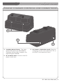
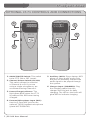
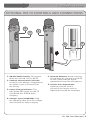
1
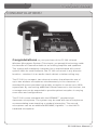
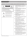
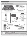
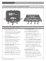
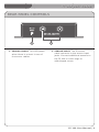
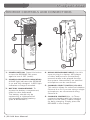
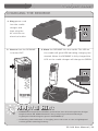
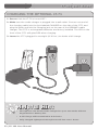
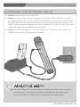
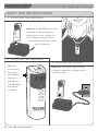
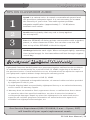
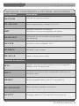
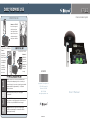
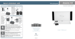
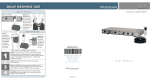
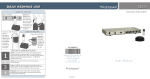
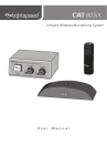
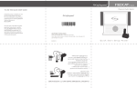
DAILY REDMIKE USE
FP 100
Classroom Audio System
START OF THE DAY
Remove the REDMIKE
from the charger and
place it around your
neck. Adjust the neck
strap so the top of the
microphone rests just
below your collarbone.
TURN ON THE REDMIKE
Turn the
microphone
ON using the
ON/OFF switch
on the side of
the REDMIKE
and speak
normally. Set
the channel
switch to A.
1
2
3
4
CHARGE BATTERIES
Return the
REDMIKE to
the cradle
charger and
recharge the
REDMIKE at
the end of
the day.
Speak in a natural voice. A normal conversational speech
level will provide an adequate signal. It is not necessary to
increase the intensity of your voice—the audio system provides
adequate amplification (approximately 5 – 10 dB) above
ambient room noises.
Avoid wearing jewelry that may rub or bump against
the microphone.
AC-MN100
Li g h tspe e d Te c hno lo gie s, Inc .
1 1 5 0 9 SW H e rman R d
Tualat in, OR 9 7 0 6 2
800.732.8999
w ww. light spe e d-t e k . c o m
Turn the REDMIKE off during private conversations with a
student, parent, or other classroom visitor. You can also cover
the LED lens on top of the REDMIKE to block the signal.
Recharge batteries each night. When recharged nightly,
operating time (actual usage) for the transmitters will last
through a typical school day.
MK-MN0010908-1
User Manual
FP 100 User Manual
CONGRATULATIONS!
Congratulations on your purchase of the FP 100 Infrared
Wireless Microphone System! This simple, yet powerful technology adds
the benefits of Classroom Audio to an existing amplifier and speakers.
This system will seamlessly integrate into a sophisticated A/V control
system. With its small footprint, the FP 100 can mount in any discrete
location— whether it is an audio visual cabinet or below-ceiling tray.
The FP 100 is a compact, two-channel receiver that allows the use of
up to two wireless microphones simultaneously in the classroom. A
standard IR sensor provides high quality reception in rooms up to 1600
square feet. By connecting additional infrared sensors to the receiver, the
coverage area can be expanded to provide optimal reception in varying
room sizes and configurations.
The FP 100 comes standard with the REDMIKE™ pendant-style
classroom microphone. The system may be used with two microphones
accommodating team teaching or student interaction. The second
microphone can be an additional REDMIKE, LightMic™ or the HM-70
handheld microphone.
FP 100 User Manual | i
FP 100 User Manual
SAFETY INSTRUCTIONS AND CERTIFICATIONS
CAUTION
RISK OF ELECTRIC SHOCK DO NOT OPEN
CAUTION: TO REDUCE THE RISK OF ELECTRIC SHOCK
DO NOT REMOVE COVER (OR BACK)
NO USER-SERVICEABLE PARTS INSIDE
REFER SERVICING TO QUALIFIED PERSONNEL
The lightning flash with arrowhead symbol
within an equilateral triangle is intended to
alert the user to the presence of uninsulated
“dangerous voltage” within the product’s
enclosure, that may be sufficient magnitude to
constitute a risk of electric shock.
The exclamation point within an equilateral
triangle is intended to alert the user to
the presence of important operating and
maintenance (servicing) instructions in the
literature accompanying the appliance.
1. Read Instructions—All safety and
operation instructions should be read
before this Lightspeed product is
operated.
2. Retain Instructions—The safety and
operating instructions should be kept
for future reference.
3. Heed Warnings—All warnings on
this Lightspeed product and in these
instructions should be followed.
4. Follow Instructions—All operating
and other instructions should
be followed.
5. Water and Moisture—This
Lightspeed product should not be
used near water.
6. Heat—This Lightspeed product should
be situated away from heat sources
such as radiators, etc.
7. Power Sources—This Lightspeed
product should be connected
to a power supply only of the
type described in the operation
instructions or as marked on this
Lightspeed product.
8. Power Cord Protection—Power
supply cords should be routed so that
they are not likely to be walked upon
or pinched by items placed upon or
against them.
9. Object and Liquid Entry—Care should
be taken so that objects do not fall
onto and liquids are not spilled into
the Lightspeed product.
10.Damage Requiring Service—This
Lightspeed product should be serviced
only by qualified service personnel.
The user should not attempt to service
this Lightspeed product.
11.Prevent Electric Shock—Do not use
this polarized plug with an extension
cord, receptacle or other outlet unless
the blades can be fully inserted to
prevent blade exposure.
ii | FP 100 User Manual
FP 100 User Manual
TABLE OF CONTENTS
FP 100 PORTABLE CLASSROOM AUDIO SYSTEM
Safety Instructions and Certifications.........................................................................ii
SECTION 1: System Overview.................................................................................. 1
System Components.............................................................................................. 2
Controls and Connections....................................................................................... 3
Rear Panel Controls................................................................................................ 4
REDMIKE Controls and Connections....................................................................... 5
Cradle Charger Controls and Connections.............................................................. 6
Optional LT-71 Controls and Connections............................................................... 7
Optional HM-70 Controls and Connections............................................................. 8
SECTION 2: Installation............................................................................................ 9
Unpacking Your System..................................................................................................... 10
Location of the Receiver/Amplifier.................................................................................. 11
IR Sensor Installation......................................................................................................... 12
Connection to the Amplifier...................................................................................14
FP 100 Mixed Audio Connection............................................................................16
Finalizing Connections...........................................................................................17
Final Check............................................................................................................17
SECTION 3: Initial Set-up, Charging and Optional Features.................................18
Initial Set-Up: REDMIKE.........................................................................................19
Initial Set-Up: Optional LT-71.................................................................................20
Initial Set-Up: Optional HM-70...............................................................................21
Charging the REDMIKE..........................................................................................22
Charging the Optional LT-71..................................................................................23
Charging the Optional HM-70................................................................................24
SECTION 4: Troubleshooting, Daily Use and Warranty.........................................25
Troubleshooting Guide...........................................................................................26
Daily Use Instructions............................................................................................27
Tips on Classroom Audio.......................................................................................28
Warranty Statement..............................................................................................28
System Specifications...........................................................................................29
Individual Components and Optional Accessories.................................................30
User Notes.............................................................................................................31
FP 100 User Manual | iii
FP 100 User Manual
SECTION 1
System Overview
1 | FP 100 User Manual
FP 100 User Manual
SYSTEM COMPONENTS
Power Supply
FP 100 Infrared Wireless
Microphone System
Audio Patch Cable
SR-70F Infrared
Sensor
Standard Option
Sensor Cable (50 ft.)
REDMIKE Classroom
Microphone
LT-71
Charging Cradle and
Power Supply
Optional Tray Mount
Sensor Cable (6 ft.)
Optional LT-71
LightMic and
Charger Cable
Optional HM-70
Handheld Microphone
and Charger Cable
Helpful Hint
Keep ALL packaging materials. If the system must be returned, using the
original packing material will be quick, convenient and prevent damage.
FP 100 User Manual | 2
FP 100 User Manual
CONTROLS AND CONNECTIONS
2
1
3
3
4
5
6
7
8
Front and Top Panel Controls
1. CH. A VOLUME: sets the nominal
volume level of the teacher
microphone (transmitter switched
to CH A). Rotating the adjustment
knob clockwise increases the
output level.
2. CH. B VOLUME: sets the nominal
volume level of the optional
second microphone (transmitter
switched to CH B). Rotating
the adjustment knob clockwise
increases the output level.
3. IR INDICATORS (IR): These lights
will glow red when the
corresponding transmitter is
turned on and being received.
This light confirms the FP 100 is
receiving a steady infrared signal.
4. AF INDICATORS (IR): These lights
flash green when audio (voice)
from the microphone is detected.
3 | FP 100 User Manual
5. DC POWER INPUT: Plug the 24V
power supply into this jack.
6. CH. A AUDIO OUTPUT: This
balanced audio output can be
connected to a microphone or line
input on a mixer/amplifier to
amplify the audio signal from the
CH. A transmitter.
7. CH. B / MIXED AUDIO OUTPUT:
This balanced audio output sends
the audio from the microphone set
to CH. B. Both CH. A and CH. B
transmitters (depending on the
position of the B/MIX switch) are ouput to a microphone or line input
on a mixer/amplifier.
8. B/MIX SWITCH: This switch
determines the audio source
that is output through the CH.B/
MIXED Audio Output jack. When
the switch is set to ‘MIX’ (default),
both the CH. A and CH. B signal are
output through this jack.
FP 100 User Manual
REAR PANEL CONTROLS
1
1. SENSOR SHORT: This LED glows
when there is a short in one of
the sensor cables.
2
2. SENSOR INPUT: The IR sensor
cable connects to the sensor input
jacks. Connect additional sensors to
the FP 100 to cover large or
odd-shaped rooms.
FP 100 User Manual | 4
FP 100 User Manual
REDMIKE CONTROLS AND CONNECTIONS
1
4
5
2
3
6
1. POWER BUTTON: Press this button
to turn the REDMIKE ON, press
again to turn it OFF (mute).
2. POWER/LOW BATTERY INDICATOR:
A BLUE light indicates the REDMIKE
is on and fully charged. A RED light
indicates a charge is needed.
3. Battery Compartment: To
access the battery compartment,
slide the door downward.
The battery should only be
replaced by a Lightspeed AA
rechargeable sensing battery
(part # BA-NH2A27).
5 | FP 100 User Manual
4. AUDIO/MICROPHONE INPUT: Use this
input to plug in a laptop, MP3 player
or other audio source to wirelessly
transmit audio to be played through
the system. Alternatively, an external
microphone can be connected.
5. CHANNEL SELECT SWITCH (CH A/B):
This switch allows for selection between
Channel A or B. If you are using a single
microphone, we recommend using
Channel A.
6. Charger Contacts (+ -): These
contacts interface with the charging
tabs in the BC-RMCC cradle charger
for daily charging. Simply place the
REDMIKE in the charger.
FP 100 User Manual
CRADLE CHARGER CONTROLS AND CONNECTIONS
1
2
3
1. CHARGE INDICATORS: The light
glows RED while the REDMIKE is
charging. When fully charged, the
light will glow GREEN.
3. OPTIONAL CHARGING PORT: Plug the
charging cord for the optional LT-71 or
the HM-70 microphones here.
2. DC POWER PORT: Connect the DC
power cord here.
FP 100 User Manual | 6
FP 100 User Manual
OPTIONAL LT-71 CONTROLS AND CONNECTIONS
4
5
1
6
1. ON/OFF/MUTE Switch: This switch
turns LT-71 ON or OFF (mute).
2. Channel Select Switch (CH A/B): This switch allows for selection
of Channel A or B. If you are
using a single microphone, we
recommend using Channel A.
3. Power/Charge Indicator: The
light glows BLUE when the LT-71
is powered ON, RED when being
charged.
4. External Microphone Input (MIC):
Use the 3.5mm MIC jack for the
optional TK-250 headset microphone
(part# MC-TK250LTM).
7 | FP 100 User Manual
LT-71
LT-71
2
3
5. Auxiliary (AUX): Plug a laptop, MP3
player or other audio source into
this jack to wirelessly transmit the audio signal to be played through the system.
6. Charger Input (CHARGER): Plug
the charging cable from the charger into this jack for daily
charging. The LED on the front will
glow RED to indicate charging.
FP 100 User Manual
OPTIONAL HM-70 CONTROLS AND CONNECTIONS
3
1
4
NiMH
6
2
5
1.ON/OFF/MUTE Switch: This switch
turns the unit ON, OFF or MUTE.
2.Channel Select Switch (CH A/B): Located in the battery compartment, the switch is set to Channel B at
the factory.
3.Power/Charge Indicator: The
light glows RED when the HM-70
is powered ON, GREEN when charging.
5.Infrared Emitters: Avoid covering the emitters as you grip the HM-70 as this could interrupt signal transmission from the microphone.
6.Volume Gain Adjustment:
Optimum volume level is
pre-set at the factory and no
adjustment should be necessary.
4.Charger Input (CHARGER): Plug
the charging cable from the charger
into this jack for daily charging.
FP 100 User Manual | 8
FP 100 User Manual
SECTION 2
Installation
9 | FP 100 User Manual
FP 100 User Manual
1. UNPACKING YOUR SYSTEM
Ensure that you have received all of the components of your system.
Power Supply
FP 100 Infrared Wireless
Microphone System
Audio Patch Cable
SR-70F Infrared
Sensor
Sensor Cable
REDMIKE Classroom
Microphone
LT-71
Charging Cradle and
Power Supply
Optional Tray Mount
Sensor Cable (6 ft.)
Optional LT-71
LightMic and
Charger Cable
Optional HM-70
Handheld Microphone
and Charger Cable
FP 100 User Manual | 10
FP 100 User Manual
2. LOCATION OF THE RECEIVER/AMPLIFIER
•Before running wires to the FP 100 or
plugging in, find a suitable, stable location
for the amplifier. Ideally, the teacher should
have ready access and an electrical outlet
should be within six feet. The best possible
location for the FP 100 is in a media cabinet
with any existing audio/video equipment.
• Wires should be routed back directly to the
amplifier, so select a location that is free from
obstructions that may make routing wire
difficult.
(Example: placing the FP 100 near
a whiteboard or bulletin board
would require the wiring
to be run an extra
distance in
order to reach
the amplifier.)
Avoid!
11 | FP 100 User Manual
FP 100 User Manual
3. IR SENSOR INSTALLATION
Sensor location is very important for optimum performance of the FP 100 Classroom
Audio System.
• BEST: On the ceiling at or near the middle of the classroom.
•GOOD: High and centered on the long wall.
• AVOID: Locations in corners, on walls at heights lower than 7 feet, or in places where the line of sight could be obstructed.
Good placement
Best placement
Avoid!
FP 100 User Manual | 12
FP 100 User Manual
IR SENSOR INSTALLATION (cont’d)
Suspended Ceiling Mount
Wall/Solid Ceiling Mount
wall
mounting
strip
c-clip
sensor plug
1. Lift the ceiling tile nearest the grid
rail in your desired sensor location.
Guide one side of the C-clip over
one edge of the grid rail. Providing
firm support to the back of the
grid rail with one hand (to prevent
bending), firmly and carefully snap
the second side of the C-clip over
the edge of the rail.
2. Uncoil sensor wire. Connect one
end of the sensor cable to the
plug on the sensor. Secure wire
overhead and route it back to
the system.
1. Screw the plastic mounting strip to
a place high on the wall or in the
middle of the solid ceiling. Mount the
strip horizontally as shown above.
2. Firmly snap the C-clip on the back
of the IR sensor onto the plastic
mounting strip with the sensor plug
hanging down (if a wall mount)
or toward the receiver location (if
ceiling mount).
3. Uncoil the sensor wire. Screw one
end of the sensor cable to the plug
on the sensor. Route the wire back to
the system, securing it along
the way.
4. Connect the other end of the sensor
cable to one of the sensor inputs on
the back of the system.
3. Connect the other end of the
sensor cable into one of the sensor
inputs on the back of the system.
Helpful Hint
Note that the sensor cable included for the optional tray mount version of
the FP 100 is only 6 feet long.
13 | FP 100 User Manual
FP 100 User Manual
4. CONNECTION TO THE AMPLIFIER
1. Locate the audio patch cable
2. Strip the cable’s rubber insulation ½” and then strip the outer sheath of the
signal wire leaving ¼” exposed.
FP 100 User Manual | 14
FP 100 User Manual
CONNECTION TO THE AMPLIFIER (cont’d)
3. Insert the stripped wires into the marked openings, left and right, in
the Euro-block.
Euro-block
4. Secure the inserted wires by tightening the retaining screws.
15 | FP 100 User Manual
FP 100 User Manual
CONNECTION TO THE AMPLIFIER (cont’d)
4. Ensure the B/MIX switch is pushed to the right to select the MIXED output.
5. Connect the ¼˝ connector into the
audio or microphone input on the
existing amplifier.
FP 100 Mixed Audio Connection (Not Recommended)
This method allows for individual control of each microphone channel from the
amplifier being used.
a. Obtain a second balanced audio cable.
b. Strip the wire to reveal the positive, negative, and grounded conductors.
c. Fasten the wire to the available CH A euro-block connector using a small screw
driver (observe the proper polarity).
FP 100 User Manual | 16
FP 100 User Manual
FINALIZING CONNECTIONS
1. Ensure all top panel volume
controls are turned fully
counterclockwise.
3. Ensure sensor cable is attached
2. Ensure audio output connection(s) are
securely connected into the FP 100 and the
mixer/amplifier. Make sure the CH.B/MIX
switch is in the appropriate setting based on your output method (see pg. 11 for
more info).
4. Ensure DC barrel end of the power
supply is connected to the DC input
on the FP 100.
securely.
5. Ensure AC adaptor end of the power
supply is connected to a standard 110 VAC electrical wall outlet.
FINAL CHECK
1. Ensure all cables are appropriately routed out of walking paths and work areas to prevent safety hazards to individuals in the room.
2. The receiver packing material should be kept for warranty shipping purposes.
Dispose of remaining system-packing material in the appropriate refuse containers.
Leave microphones charging so they are ready for use.
Microphones will need to be charged on a daily basis.
17 | FP 100 User Manual
FP 100 User Manual
SECTION 3
Initial Set-up, Charging and
Optional Features
FP 100 User Manual | 18
FP 100 User Manual
INITIAL SET-UP: REDMIKE
1. Turn on the REDMIKE. The RED IR LED on
the FP 100 will light to indicate a signal is
being received.
2. Slip the REDMIKE with lanyard around the neck
and position the top of the microphone just below
the collarbone. NOTE: Positioning of the REDMIKE is
critical for proper volume adjustment.
3. Set the volume on the mixer/amplifier at a normal level. This will be the primary
control the teacher will use to turn the microphone
volume(s) up and down.
4. While speaking in a normal voice, increase
the A VOLUME level until your own voice is
barely audible. REMEMBER: this equipment
is designed to supplement and distribute the
teacher’s voice so he or she is able to speak
at a normal, conversational tone. Having the
volume set too high will result in feedback
and listener fatigue.
5. If a second REDMIKE was purchased, repeat
steps 2-4. NOTE: Each REDMIKE has its Channel
pre-set to either A or B. No further adjustment is
necessary.
6. Once the normal level is set on the FP 100, the
user will now use the mixer/amplifier volume
control to adjust the microphone up or down
during normal classroom operation.
19 | FP 100 User Manual
FP 100 User Manual
INITIAL SET-UP: OPTIONAL LT-71
1. Turn on the LT-71 and set the operating
channel to “B”.
A CH B
OFF
ON
2. Slip the LT-71 with lanyard around
the neck and position the top of the
microphone just below the collarbone.
NOTE: Positioning of the LT-71 is critical
for proper volume adjustment.
3. While speaking in a normal voice, increase
the B VOLUME level until your own voice is
barely audible. REMEMBER: this equipment
is designed to supplement and distribute
the teacher’s voice so he or she is able to
speak at a normal, conversational tone.
Having the volume set too high will result in
feedback and listener fatigue.
4. Once the normal level is set on the FP 100, the user will now use the mixer/
amplifier volume control to adjust the microphone up or down during normal
classroom operation.
Existing Amplifier
FP 100 User Manual | 20
FP 100 User Manual
INITIAL SET-UP: OPTIONAL HM-70
2. Turn on the HM-70 by sliding the switch to
the top position.
3. Grip the barrel in the center section.
Avoid covering the infrared emitters
circling the base. This could interrupt
signal transmission.
3. While speaking in a normal voice, increase
the B VOLUME level until your own voice is
barely audible. REMEMBER: this equipment
is designed to supplement and distribute
the teacher’s voice so he or she is able to
speak at a normal, conversational tone.
Having the volume set too high will result in
feedback and listener fatigue.
4. Once the normal level is set on the FP 100, the user will now use the mixer/
amplifier volume control to adjust the microphone up or down during normal
classroom operation.
Existing Amplifier
21 | FP 100 User Manual
FP 100 User Manual
CHARGING THE REDMIKE
1. Plug power cord
into the cradle
charger and
then plug the
AC end into an
electrical outlet.
2. Ensure that the REDMIKE
is turned OFF.
3. Place the REDMIKE into the cradle. The LED on
the cradle will glow RED indicating charging has
started. When the REDMIKE is fully charged the
LED on the cradle charger will change to GREEN.
Helpful Hint
• REDMIKE incorporates alkaline protection into the microphone design.
Replacement AA NiMH batteries may only be purchased through
Lightspeed Technologies (part # BA-NH2A27).
• A blinking LED indicates a charging error. Be sure to use a Lightspeed
rechargeable sensing battery.
FP 100 User Manual | 22
FP 100 User Manual
CHARGING THE OPTIONAL LT-71
1. Ensure that the LT-71 is turned OFF.
2. Make sure the cradle charger is plugged into a wall outlet. Connect one end of
the charging cable into the jack labeled CHARGER on the side of the LT-71 and
plug the other end into the charging jack on the rear of the REDMIKE cradle
charger. The LT-71’s rechargeable batteries are factory installed. The LED on the
front of the LT-71 will glow RED when charging.
3. Leave the LT-71 plugged in overnight (8–10 hrs.) to obtain a full charge.
Helpful Hint
• Microphones can be left in the charger for up to two weeks without
degradation to battery life.
• A full charge will be attained in 8-10 hours.
• Fully charged Lightspeed microphones will last over 7 hours.
23 | FP 100 User Manual
FP 100 User Manual
CHARGING THE OPTIONAL HM-70
1. Ensure that the HM-70 is turned OFF.
2. Make sure the cradle charger is plugged into a wall outlet. Connect one end of
the charging cable into the jack labeled CHARGER on the side of the HM-70 and
plug the other end into the charging jack on the rear of the cradle charger. The
HM-70’s rechargeable batteries are factory installed. The LED on the front of the
Handheld Mic will glow GREEN when charging.
3. Leave the HM-70 plugged in overnight (8–10 hrs.) to obtain a full charge. The
GREEN light will turn off when fully charged.
Helpful Hint
Do not attempt to charge alkaline batteries. They can overheat
and expand, creating a significant hazard and damaging the
LT-71 and HM-70. (This is not covered by the warranty.)
FP 100 User Manual | 24
FP 100 User Manual
SECTION 4
Troubleshooting, Daily Use
and Warranty
25 | FP 100 User Manual
FP 100 User Manual
TROUBLESHOOTING GUIDE
Note: Most problems are directly related to low battery power. Please run through the “Battery
Check” items first. For remaining troubleshooting, use known good, fully-charged batteries.
Battery Check
No Sound From Speaker
• Confirm batteries are charged
• Ensure the FP 100 is powered on.
each night.
• Confirm proper batteries are used.
The REDMIKE requires the Lightspeed
BA-NH2A27 rechargeable sensing
battery for proper charging. The LT-71
& HM-70 require NiMH AA rechargeable
batteries.
• Make sure the microphones are turned
off while charging so a full charge is
attained. Full charge will last eight
hours.
• Inspect the battery contacts. Clean and
adjust if necessary.
Hearing Static
• Ensure sensor is in optimum location
(refer to sensor placement in manual).
A single sensor will cover a 1600 sq. ft.
enclosed classroom.
• Ensure that no other REDMIKE/LT71/
HM70 is operating on the same channel.
Low Volume or Feedback
• Ensure microphone is positioned
appropriately, just below the collar
bone.
Unplug the DC power cable and plug
it back in. The LED lights will blink to
indicate the unit is powered on.
• Confirm signal is being received at the
FP 100. The IR signal light will be RED
indicating a signal is being received.
• Confirm that REDMIKE is turned on.
There will be a BLUE LED on
the microphone to indicate it is
powered on.
•Ensure the IR sensor is receiving
power as indicated by a red LED on
one side of the unit—this should be
easily visible from the ground.
•If no indicator lights are present on
the FP 100, ensure it is receiving
power. Unplug the DC power jack
and re-connect. If the receiver is
receiving power, the IR and AF lights
will flash on when reconnected to a
power source.
•Ensure the separate mixer/amplifier
is operating properly as a standalone system.
• Check volume level on the amplifier. If
the volume is too high, feedback will
occur. Adjust accordingly.
• Check volume levels on the FP 100.The
screwdriver adjust controls should be
set at a normal level so that volume is
appropriate for the classroom when the
corresponding mixer/amplifier volume
level is at mid-range. Adjust the levels
up or down accordingly.
If you review these instructions and still have questions, write down the serial
number and model number of your system and call Lightspeed Technical Services at
800.732.8999, 5 a.m. – 5 p.m., PST.
FP 100 User Manual | 26
FP 100 User Manual
DAILY USE INSTRUCTIONS
1. POSITION THE REDMIKE
Remove the REDMIKE from the
charging cradle and place it
around your neck. Adjust the
neck strap so the top of the
microphone rests just below
your collarbone.
2. TURN ON THE REDMIKE
3. CHARGE BATTERIES
Turn the
Place the REDMIKE back into the
microphone
charging cradle to recharge at the
ON using
end of the day.
the ON/OFF
switch on
the side of
the REDMIKE
and speak
normally.
27 | FP 100 User Manual
FP 100 User Manual
TIPS ON CLASSROOM AUDIO
1
2
3
4
Speak in a natural voice. A normal conversational speech level
will provide an adequate signal. It is not necessary to increase
the intensity of your voice—the audio system provides
adequate amplification (approximately 5 – 10 dB) above
ambient room noises.
Avoid wearing jewelry that may rub or bump against
the microphone.
Turn the REDMIKE off during private conversations with a student,
parent, or other classroom visitor. You can also cover the LED
lens on top of the REDMIKE to block the signal.
Recharge batteries each night. When recharged nightly, operating time (actual usage) for the transmitters will last through a typical school day.
Five-year Limited Warranty
Lightspeed Classroom Audio Systems are guaranteed against malfunction due to defects
in materials and workmanship for a period of FIVE (5) YEARS, beginning at the date of
the purchase invoice. If such malfunction occurs, the product will be repaired or replaced
(at Lightspeed’s option) without charge during the warranty period.
1. Warranty on infrared microphones is FIVE (5) YEARS.
2. Warranty on Lightspeed rechargeable batteries, all external cables and wires provided
by Lightspeed is one (1) year.
3. Prepaid shipping labels are provided by Lightspeed factory or an authorized warranty
service center for warranty repairs.
4. Warranty does not extend to finish, appearance items, or malfunctions due to abuse
or operation other than specified conditions, nor does it extend to incidental or
consequential damages. Repair by other than Lightspeed or its authorized service
agencies will void this guarantee. Information on authorized service agencies is
available from Lightspeed Technologies, Inc.
Our Service Department (800.732.8999, 5 a.m. – 5 p.m., PST)
will handle all your repair/replacement needs.
FP 100 User Manual | 28
FP 100 User Manual
SYSTEM SPECIFICATIONS
OVERALL SPECIFICATIONS
Carrier Frequencies (IR)........................................ 2.06/2.54; 3.2/3.7 MHz
Signal-to-Noise Ratio............................................. > 73 dB
Dynamic Range..................................................... > 73 dB
Maximum Deviation.............................................. ±50 Hz
Frequency Stability............................................... ±3%
Frequency Response............................................. 100 Hz - 10k Hz
Audio Output Level............................................... 0 - 1.0 V
RECEIVER SPECIFICATIONS
Receiver Type........................................................ Superheterodyne
Receiver Sensitivity............................................... 6 µV for 60 dB S/N
Image and Spurious Rejection............................... > 70 dB
Reception Selectivity............................................ 40 kHz
Squelching Mute Level.......................................... 3.2 µV
Dimensions (W x D x H)........................................ 5” x 5” x 1.25”
Power Supply (UL Listed)...................................... 24 V/250 mA
Weight................................................................... 15.3 oz
TRANSMITTER SPECIFICATIONS
REDMIKE
Audio Distortion.................................................... < 1 %
Built-in Microphone............................................... Unidirectional Electret
Battery Power (1-year warranty)........................... 1 AA NiMH Rechargeable
Sensing Battery
Audio Input........................................................... 3.5 mm
Dimensions (W x D x H)........................................ 0.9” x 1.0” x 3.5”
Weight................................................................... 2.1 oz.
LT-71 LightMic
Audio Distortion.................................................... < 1 %
Built-in Microphone............................................... Unidirectional Electret
Battery Power (1-year warranty)........................... 2 AA NiMH Rechargeable
Audio Inputs.......................................................... Mic Level 3.5 mm
Line Level 3.5 mm
Dimensions (W x D x H)........................................ 1.375” x .75” x 4.625”
Weight................................................................... 3.7 oz.
HM-70 Handheld Microphone
Audio Distortion.................................................... < 1 %
Built-in Microphone............................................... Unidirectional Electret
Battery Power (1-year warranty)........................... 2 AA NiMH Rechargeable
Dimensions (W x D x H)........................................ 2.25” x 2.25” x 8.75”
Weight................................................................... 7.36 oz.
IR SENSOR SPECIFICATIONS
Working Range...................................................... Up to 1600 square feet per sensor
Cable..................................................................... 50 ft., Plenum-rated
Mounting............................................................... Ceiling clip/Wall bracket
Dimensions........................................................... 4.25” (Diam.) x 2.0” (H)
Weight................................................................... 4.5 oz.
29 | FP 100 User Manual
FP 100 User Manual
INDIVIDUAL COMPONENTS & OPTIONAL ACCESSORIES
Part Number
Description
RX-FP100
Infrared microphone receiver
PS-24V-250
Power supply/battery charger for FP 100
RMT
REDMIKE classroom microphone
w/lavaliere cord and rechargeable AA battery
BA-NH2A27
Lightspeed AA rechargeable sensing battery
(for REDMIKE)
AC-LTCB
Lavaliere cord for REDMIKE, LT-71
BC-RMCC
REDMIKE cradle charger
PS-5V-1.0
Cradle charger power supply
Optional Accessories
LT71
LightMic microphone with lavaliere cord, rechargeable
batteries and charging cable
HM70
Handheld microphone with rechargeable batteries and
charging cable
BA-NH1
AA Rechargeable battery (for LT-71 and HM-70)
MC-TK250LTM
Noise-canceling headset microphone
AC-TCC7
Charging cable for LT-71 and HM-70 microphones
FP 100 User Manual | 30
FP 100 User Manual
USER NOTES
Record your system serial numbers and
purchase information. This is helpful
when ordering additional components,
accessories, and/or warranty service.
Components
FP 100
Microphones
Sensors
Accessories
Purchase Information
Your School/Organization
District
Purchase Date
Invoice
31 | FP 100 User Manual
Serial Number
FP 100 User Manual
USER NOTES
FP 100 User Manual | 32
FP 100 User Manual
USER NOTES
33 | FP 100 User Manual
DAILY REDMIKE USE
FP 100
Classroom Audio System
START OF THE DAY
Remove the REDMIKE
from the charger and
place it around your
neck. Adjust the neck
strap so the top of the
microphone rests just
below your collarbone.
TURN ON THE REDMIKE
Turn the
microphone
ON using the
ON/OFF switch
on the side of
the REDMIKE
and speak
normally. Set
the channel
switch to A.
1
2
3
4
CHARGE BATTERIES
Return the
REDMIKE to
the cradle
charger and
recharge the
REDMIKE at
the end of
the day.
Speak in a natural voice. A normal conversational speech
level will provide an adequate signal. It is not necessary to
increase the intensity of your voice—the audio system provides
adequate amplification (approximately 5 – 10 dB) above
ambient room noises.
Avoid wearing jewelry that may rub or bump against
the microphone.
AC-MN100
Li g h tspe e d Te c hno lo gie s, Inc .
1 1 5 0 9 SW H e rman R d
Tualat in, OR 9 7 0 6 2
800.732.8999
w ww. light spe e d-t e k . c o m
Turn the REDMIKE off during private conversations with a
student, parent, or other classroom visitor. You can also cover
the LED lens on top of the REDMIKE to block the signal.
Recharge batteries each night. When recharged nightly,
operating time (actual usage) for the transmitters will last
through a typical school day.
MK-MN0010908-1
User Manual