1
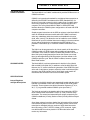
OPERATOR'S MANUAL
MODEL 8901A
CAMAC-TO-GPIB INTERFACE
(FAN 2016)
1
Innovators in Instrumentation
Corporate Headquarters
700 Chestnut Ridge Road
Chestnut Ridge, NY 10977-6499
Tel: (914) 578-6013 Fax: (914) 578-5985
E-mail: [email protected]
[email protected]
Copyright© July 1997. LeCroy™ is a registered trademark of
LeCroy Corporation. All rights reserved. Information in this
publication supersedes all earlier versions.
2
CE CONFORMITY
CONDITIONS FOR
CE CONFORMITY
Since this product is a subassembly, it is the responsibility of the end
user, acting as the system integrator, to ensure that the overall system is
CE compliant. This product was demonstrated to meet CE conformity
using a CE compliant crate housed in an EMI/RFI shielded enclosure. It
is strongly recommended that the system integrator establish these
same conditions.
3
4
CAUTION
INSTALLATION
Crate power should be turned off during insertion or removal of modules
to avoid possible damage caused by momentary misalignment of contacts.
SPECIFICATIONS
The information contained in this manual is subject to change without
notice. The reference for product specification is the Technical Data
Sheet effective at the time of purchase.
5
6
TABLE OF CONTENTS
1.
2.
3.
4.
5.
General Information
Purpose
Unpacking and Inspection
Warranty
Product Assistance
Maintenance Agreements
Documentation Discrepancies
Service Procedures
9
9
9
9
9
10
10
Product Description
The 8901A and the CAMAC Standard
Upgrade Notes
Specifications
Internal Registers and Byte Descriptions
CAMAC Cycle Execution
CLEAR, INITIALIZE and INHIBIT
Block Transfer Mode
Service Requests (SRQ)
Serial Poll
Front Panel LEDs
GPIB Device Address Switch
General
11
11
11
11
12
12
12
12
12
12
13
13
Installation
Setup of Jumpers and Mechanical Switches
GPIB Address
Byte Order Jumpers
Installation in Mainframe
15
15
15
15
Operating Instructions
Introduction
Instrument Drivers and Example Source Code
Command Types
8901A Setup Command Information
Transfer Mode Commands
SRQ Setup Commands and Responses
CAMAC Commands
The C, Z and I Commands
Commands to Individual Modules
Programming the 8901A and Other CAMAC Modules
General
LISTEN, TALK, UNLISTEN: GPIB Bus Actions
Uploading Command Byte(s) to the 8901A
Procedure for 8901A Setup Commands
Procedure for C, Z, and I Commands
Procedure for Commands Sent to Individual Moduels
Procedure for Readout of Data into Computer
Programming Example: Sample Source Code
17
17
17
17
17
18
19
19
20
20
20
20
21
21
21
22
23
24
Theory Of Operation
General
GPIB Command Decoder
Acceptor Handshake
LISTEN Mode
Global CAMAC Commands
31
31
32
32
32
7
F,A,N CAMAC Commands
Transfer Mode
Serial Poll Mode
TALK Mode
Source Handshake
CAMAC Cycle Timing
Read Data
X and Q Response
LAM Lines
SRQ Generation
6.
7.
8
32
32
33
33
33
33
33
33
34
34
Appendix
AN-33 "An Introduction to CAMAC"
35
Index
45
GENERAL INFORMATION
PURPOSE
UNPACKING AND
INSPECTION
WARRANTY
This manual is intended to provide instruction regarding the setup and
operation of the covered instruments. In addition, it describes the theory
of operation and presents other information regarding its functioning and
application.
It is recommended that the shipment be thoroughly inspected immediately upon delivery. All material in the container should be checked
against the enclosed Packing List and shortages reported promptly.
If the shipment is damaged in any way, please notify the Customer
Service Department or the local field service office. If the damage is
due to mishandling during shipment, you may be requested to assist in
contacting the carrier in filing a damage claim.
LeCroy warrants its instrument products to operate within specifications
under normal use and service for a period of one year from the date of
shipment. Component products, replacement parts, and repairs are
warranted for 90 days. This warranty extends only to the original purchaser. Software is thoroughly tested, but is supplied "as is" with no
warranty of any kind covering detailed performance. Accessory products
not manufactured by LeCroy are covered by the original equipment
manufacturers' warranty only.
In exercising this warranty, LeCroy will repair or, at its option, replace any
product returned to the Customer Service Department or an
authorized service facility within the warranty period, provided that the
warrantor's examination discloses that the product is defective due to
workmanship or materials and has not been caused by misuse, neglect,
accident or abnormal conditions or operations.
The purchaser is responsible for the transportation and insurance
charges arising from the return of products to the servicing facility.
LeCroy will return all in-warranty products with transportation prepaid.
This warranty is in lieu of all other warranties, express or implied, including but not limited to any implied warranty of merchantability, fitness, or
adequacy for any particular purpose or use. LeCroy shall not be liable
for any special, incidental, or consequential damages, whether in contract, or otherwise.
PRODUCT ASSISTANCE
MAINTENANCE
AGREEMENTS
Answers to questions concerning installation, calibration, and use of
LeCroy equipment are available from the Customer Service Department,
700 Chestnut Ridge Road, Chestnut Ridge, New York, 10977-6499,
(914) 578-6030.
LeCroy offers a selection of customer support services. For example,
Maintenance Agreements provide extended warranty that allows the
customer to budget maintenance costs after the initial warranty has
expired. Other services such as installation, training, on-site repair, and
addition of engineering improvements are available through specific
Supplemental Support Agreements. Please contact the Customer
Service Department for more information.
9
DOCUMENTATION
DISCREPANCIES
SERVICE PROCEDURE
10
LeCroy is committed to providing state-of-the-art instrumentation and is
continually refining and improving the performance of its products. While
physical modifications can be implemented quite rapidly, the corrected
documentation frequently requires more time to produce. Consequently,
this manual may not agree in every detail with the accompanying product
and the schematics in the Service Documentation. There may be small
discrepancies in the values of components for the purposes of pulse
shape, timing, offset, etc., and, occasionally, minor logic changes.
Where any such inconsistencies exist, please be assured that the unit is
correct and incorporates the most up-to-date circuitry.
Products requiring maintenance should be returned to the Customer
Service Department or authorized service facility. If under warranty,
LeCroy will repair or replace the product at no charge. The purchaser is
only responsible for the transportation charges arising from return of the
goods to the service facility. For all LeCroy products in need of repair
after the warranty period, the customer must provide a Purchase Order
Number before any inoperative equipment can be repaired or replaced.
The customer will be billed for the parts and labor for the repair as well
as for shipping. All products returned for repair should be identified by
the model and serial numbers and include a description of the defect or
failure, name and phone number of the user. In the case of products
returned, a Return Authorization Number is required and may be
obtained by contacting the Customer Service Department at (914) 5786030.
PRODUCT DESCRIPTION
THE 8901A and the
CAMAC STANDARD
The Model 8901A is a CAMAC module which provides GPIB access to a
CAMAC mainframe.
CAMAC is an international standard for modularized instrumentation as
defined by the ESONE Committee and the IEEE (Standard 583). Its
function is to provide a means by which a wide range of modular instruments can be powered in a multi-receptacle crate and interfaced to a
computer. The LeCroy Model 8901A CAMAC to GPIB (IEEE 488)
interface allows the CAMAC system configuration to be used with GPIB
computer controllers.
Simple program instructions via the GPIB to registers in the Model 8901A
select an individual instrument module within the CAMAC mainframe,
select any subaddress within that module, and establish the function
(read, write, control). This allows the user to handle the entire CAMAC
mainframe of up to 23 individual instrument modules in the same manner
as any ordinary single device connected to the IEEE-488 bus. It is
possible to interconnect up to 15 different CAMAC mainframes in this
way.
The 8901A can be programmed to do a block transfer of all data within a
CAMAC module to a GPIB Listener without additional intermediate
commands. In this mode, the 8901A will alternately transfer one, two or
three 8-bit bytes (as programmed) as fast as the Listener can accept
them (at rates approaching 500 kilobytes/sec) and then initiate a new
CAMAC acquisition cycle. Not all CAMAC modules, however, support
Block Read readout.
UPGRADE NOTES
The Model 8901A is a direct replacement for both the LeCroy Model
8901 and 8901/100 (Mod 100). In addition to all of the 8901-8901/100
features, the "A" version includes the generation of the GPIB EOI signal
at the end of valid data, a jumper to select the order in which data bytes
are sent to the GPIB controller, and a "slow" block mode transfer for
instruments that cannot be read out at full CAMAC speed.
SPECIFICATIONS
Internal Registers
and Byte Descriptions
Registers in the 8901A Interface are sequentially loaded with data after it
has been commanded to enter the LISTEN mode by the GPIB System
Controller. These registers store all the information necessary (F, A, N,
W, C, Z, I) to generate standard CAMAC cycles (see Table 1).
The first byte received by the interface after it has entered the LISTEN
mode contains either the CAMAC Function (F Code) or 8901A Setup
information. The second and sequential bytes accept, respectively, the
CAMAC subaddress (A Code), station number (N Code) and three bytes
of data.
Once these registers have been loaded, the information will be retained
until modified or power is turned off. The loading process can be terminated (and re-initialized) after any number of bytes have been transferred by issuing a TALK, LISTEN, Unlisten or IFC command. Again,
note that the 8901A must be placed in LISTEN mode before it will
receive any information.
11
Table 1: Register Descriptions
Register Name
F
A
N
D1
D2
D3
CAMAC Cycle Execution
CLEAR, INITIALIZE
and INHIBIT
12
Register Description
Contains Function code OR Setup Command
Module Subaddress
CAMAC station (slot) number
Low data byte (bits W1-W8 on CAMAC Dataway)
Middle data byte (bits W9-W16)
High data byte (bits W17-W24)
A CAMAC cycle is executed every time the 8901A is commanded to
enter the TALK mode and a Service Request is not pending. At the
completion of the CAMAC cycle a DAV (Data Valid) will be asserted.
Every time a byte is accepted a new byte is made available. When no
more data is available, the 8901A asserts End of Identity (EOI).
The 8901A can be programmed to generate CLEAR (C), INITIALIZE (Z),
or INHIBIT (I) signals on the dataway when a CAMAC cycle is executed.
The C and Z registers are cleared after the completion of the next
CAMAC cycle. The INHIBIT register will remain set until it is programmed
off.
Block Transfer Mode
The 8901A can be programmed to do a high speed block transfer of 8-,
16-, or 24-bit words from CAMAC modules with read and increment
capability. Following module addressing and the appropriate control byte,
(see Operating Instructions) a TALK command will start the 8901A to
read one, two, or three bytes of data and automatically initiate another
CAMAC cycle. Approximately 2 µsec later (a programmable 40 µsec
delay can be used for slow modules) new data is available to be read.
CAMAC cycles will continue to be executed until a Q=0 (end of memory)
condition causes the 8901A to stop executing CAMAC cycles and exit
the transfer mode.
Service Requests (SRQ)
The 8901A can be programmed to operate in SRQ mode. In this mode, a
Service Request will be issued after a specific condition occurs on the
CAMAC dataway, involving the dataway LAM, Q and X lines.
Serial Poll
After issuing a service request, a Serial Poll must be performed. The
8901A will send the status of the individual LAM, X and Q lines, terminating the Service Request after the controller reads the status byte. Note:
For a LAM-generated Service Request, the LAM must be cleared or
disabled before the poll is taken, or else another service request will
immediately be issued.
Front Panel LEDs
TALK: indicates when 8901A is a GPIB Talker.
LISTEN: indicates when 8901A is a GPIB Listener.
SRQ Enable: indicates when 8901A is enabled to carry out Service
Requests.
X Response: indicates a valid command was accepted by the
addressed module.
Q Response: indicates a valid data transfer or valid test within the
mainframe.
Look-at-Me: indicates when any CAMAC modules sets “LAM” line
(often used to generate a Service Request).
INHIBIT: indicates when CAMAC dataway is inhibited. (Note: the
INHIBIT LED turns on when the appropriate control byte is uploaded. A
TALK must still be executed for before other modules can be Inhibited.
GPIB Device
Address Switch
Sets the GPIB Address of the 8901A. See Figure 1 on page 15.
General
The 8901A resides in the two slots furthest right in a CAMAC mainframe
and generates all CAMAC dataway signals in response to commands
from a GPIB controller. A standard GPIB connector on the front panel
permits interconnection to any GPIB system. This allows any GPIB
controller to program settings, read from or write to any standard
CAMAC modules.
Packaging: is in conformance with CAMAC standard, RF-shielded 2
module.
Power Required: is 1.2 A at +6 V.
13
14
INSTALLATION
SETUP OF JUMPERS
AND MECHANICAL
SWITCHES
GPIB Address
Before installation in a mainframe, set the GPIB Address and Byte Order
jumpers as described in this section.
Each device connected to the GPIB must have a unique address which
the system controller uses to communicate with it. The address of the
Model 8901A is set by a DIP switch located under the GPIB connector on
the front panel. The switches are labeled A0, A1, A2, A3, A4 (representing values of 1, 2, 4, 8, 16 respectively). Valid GPIB address are 0 to 31.
Figure 1 shows an address setting of 9 as an example.
Example GPIB Address Switch Settings: Address = 9
X
X
A0
A1
X
A2
X
X
A3
(0)
(1)
A4
(X indicates switch depressed)
Figure 1
Byte Order Jumpers
On the side panel of the Model 8901A are two pair of jumpers labeled
"NORMAL" and "REVERSE". These jumpers determine the order in
which the data bytes are read out. When the jumpers are set to normal,
the least significant byte of data is read out first in multi-byte transfers.
When in the reverse byte position, a 16-bit word is read out, most
significant byte first, followed by the least significant byte. If 24-bit
transfer is selected, the order is middle byte, least significant byte and
then most significant byte. It is recommended that the reverse byte
option only be used when the computer expects the MSB before the LSB
in a 16-bit word. Caution - this jumper only controls the byte order for
reading out of the 8901A. It does not effect the data bytes uploaded to
the dataway "Write" lines.
NORMAL setting byte readback order: Byte #1, Byte #2, Byte #3
REVERSE setting byte readback order: Byte #2, Byte #1, Byte #3
INSTALLATION IN
MAINFRAME
The 8901A is compatible with any standard CAMAC mainframe.
With the power off, insert the 8901A into the Control Station location
(the two rightmost locations in the mainframe). Modules may become
damaged if inserted with power on, due to momentary misalignment of
the contacts.
Note: CAMAC mainframes with an embedded controller, like the Model
DDC3000, may not contain a Control Station.
Connect a GPIB cable from the 8901A to the GPIB interface associated
with your computer.
15
Always ensure that the mainframe has sufficient clearance at the top to
permit adequate airflow. For example, when using the 8901A in the
8013A benchtop instrument mainframe, air-blocking baffles (Models
BFP-1 and BFP-2) should be used to ensure proper cooling. Do not
obstruct ventilation by placing papers or other objects on the top of the
mainframe.
16
OPERATING INSTRUCTIONS
INTRODUCTION
Instrument Drivers and
Example Source Code
The 8901A provides GPIB control of all instruments in a CAMAC mainframe by transferring data uploaded via GPIB to the CAMAC dataway,
and by controlling the execution of CAMAC cycles.
Current versions of instrument drivers for the LabVIEW™ and
LabWindows™ packages are available from the LeCroy WWW and FTP
sites, as well as some sample source code and control programs. All
8901A sample software is not protected under the 8901A warranty.
Please also refer to the next chapter "Programming CAMAC Modules"
for information on uploading and executing commands described in this
section.
Command Types
The GPIB controller may send the 8901A two basic types of commands:
1. 8901A Setup Commands: These commands program the 8901A,
and do not involve the CAMAC dataway or other CAMAC modules.
2. CAMAC Commands: These commands are communicated
through the CAMAC dataway for programming and operation of
other instruments in the mainframe.
8901A SETUP COMMAND
INFORMATION
There are two categories of Setup Commands:
■
■
Transfer Mode Commands
SRQ (Service Request) Configuration Commands
These are all single byte commands. Please see the section
"Programming the 8901A and other CAMAC Modules" for programming
instructions.
Transfer Mode Commands
By sending the appropriate command byte (see Table 3), the 8901A can
be programmed to return 8, 16, or 24-bit data words in either single or
block word transfers over the GPIB bus. In the case of multiple byte
transfers, data is sent based on the Byte Order Jumper setting. When the
byte order is set to NORMAL the least significant byte is sent first followed
by the middle and high bytes.
In "normal" transfer modes (not to be confused with the NORMAL jumper
setting mentioned above), the 1, 2, or 3 data bytes are followed by a
status byte containing the X response (least significant bit) and the Q
response (bit 2), along with the GPIB EOI status line, which is asserted to
indicate end of the data transfer. When programmed for normal transfers,
the 8901A will await further commands after data is transferred.
Table 3 - Transfer Mode Commands
Normal
Transfer
8-bit read
16-bit read
24-bit read
97
98
100
(61)
(62)
(64)
Block
Read
121
122
124
(79)
(7A)
(7C)
High Speed
Block Read
105
106
108
(69)
(6A)
(6C)
Single byte commands - values specified in decimal with hex value given in ( )
LabVIEW™ and LabWindows™ are trademarks of National Instruments Inc.
17
In block read modes, the 8901A will transfer a block of data. The 8901A
will automatically initiate additional CAMAC cycles after downloading the
current data word(s). CAMAC cycles will continue to be executed until
the Q status line goes to 0, or until the GPIB controller terminates the
transfer.
There are two basic types of block read modes in the 8901A. The first
one, "normal block read" is provided for modules which cannot read out
at full CAMAC speed (1 MHz). In this mode, a 35 µsec delay (plus GPIB
overhead) is added between each CAMAC cycle to slow down the
transfer rate. The other mode, "high speed block read" runs as fast as
the data is read out over the GPIB, up to 2 µsec per cycle.
When block mode transfers are terminated by Q=0, two additional bytes
are sent to the GPIB controller. A status byte with the X and Q data,
followed by a zero byte and EOI.
Note: If the GPIB controller terminates the transfer before Q=0, one
additional cycle will be executed and the data will be left in the 8901A's
registers. To access this data, it is necessary to send the CAMAC
command F(0) A(0) and N(24) (see next section), and then readout the
data word. This is required since the 8901A is initiating the CAMAC
cycles in block mode transfers.
At the end of each block transfer, the 8901A is reset to the corresponding
normal transfer mode.
SRQ Setup Commands
and Responses
A service request (SRQ) is a mechanism by which a GPIB compatible
instrument can communicate to a computer that a particular condition
exists, without requiring the computer to readout any data. There are
three conditions occurring on the CAMAC bus which can be employed to
cause the Model 8901A to issue a service request to the GPIB controller:
1. When any individual LAM line is set
2. When Q is set
3. When X is set
Table 4 lists the commands to send to the 8901A to set it up to generate
a SRQ on the proper condition(s).
Table 4 - Service Request Response Commands
Disable SRQ
Enable SRQ on occurrence of LAM
Enable SRQ on occurrence of Q=0
Enable SRQ on occurrence of LAM or Q=0
Enable SRQ on occurrence of X=0
Enable SRQ on occurrence of LAM or X=0
Enable SRQ on occurrence of Q=0 or X = 0
Enable SRQ on occurrence of LAM, Q=0 or X=0
64
65
66
67
68
69
70
71
(40)
(41)
(42)
(43)
(44)
(45)
(46)
(47)
NOTE: All of these commands de-assert INHIBIT.
Single byte commands - values specified in decimal with hex value given in ( )
18
The GPIB controller must perform a serial poll of all devices after receiving a service request. When the 8901A is polled, it sends up to 5 bytes of
information to the GPIB controller. The first byte is a status byte which
contains the current state of X and Q in bits 1 (LSB) and 2 respectively
and bit 7 indicating whether or not the currently addressed 8901A was
the device which requested service. If bit 7 is equal to one, the 8901A
generated the request. The next four bytes indicate the state of the LAM
lines. They are encoded as follows:
Table 5 - Service Request Response Description
Byte #
1
2
3
4
5
Description
Status byte, with X and Q on bits 1 and 2 respectively
LAM for slots 1 through 6 (Slot 1 LAM is least significant bit)
LAM for slots 7 through 12
LAM for slots 13 through 18
LAM for slots 19 through 23
A service request by the 8901A will be cleared after the controller reads
the status byte. However, if the request was caused by a LAM, a service
request will immediately be issued again unless SRQ on LAM is disabled
in the 8901A or the LAM is cleared in the instrument(s) asserting it. It is
important to note that the 8901A cannot transfer any CAMAC commands
to the dataway while any service request is pending.
CAMAC COMMANDS
CAMAC commands are communicated through the CAMAC dataway, for
programming and operation of other instruments in the mainframe.
There are two basic types.
The C, Z, and I Commands
The 8901A can be programmed to generate CLEAR (C), INITIALIZE (Z),
or INHIBIT (I) signals on the dataway when a CAMAC cycle is executed.
These commands are visible to all instruments in the mainframe. C, Z,
and I are all single byte commands; please see the section "Programming the 8901A and other CAMAC Modules" for programming instructions. CAMAC modules may have different responses to these
commands; please check the user manual for information specific to your
modules. The "Introduction to CAMAC" Application Note (AN-33 included
at the end of this manual) contains further information regarding standard
use of the C, I and Z lines.
The CLEAR and INITIALIZE signals will be turned on only during the first
CAMAC cycle executed after the 8901A received that command. The
INHIBIT line will remain asserted until the 8901A is programmed to deassert it. Caution - changing the INHIBIT line will affect the state of the
service request response programming.
Table 6 - Z, C and I Command Control Bytes
Send INITIALIZE (Z)
Send CLEAR (C)
Send CLEAR and INITIALIZE
Assert INHIBIT (I)
De-assert INHIBIT (also disables SRQ)
33
34
35
72
64
(21)
(22)
(23)
(48)
(40)
Single byte commands - values specified in decimal with hex value given in ( )
19
Commands to
Individual Modules
The 8901A transfers Function, Subaddress, Station (or slot) number, and
up to three bytes of data to the CAMAC dataway when sending a CAMAC command. These commands are often referred to as "FAN", "FNA"
or "Function code" commands.
Table 7 - Acceptable Values for FAN Commands
Command
Component
Function code
Subaddress
Station Number
Data bytes
Abbreviation
F
A
N
D1, D2, D3
Range of Values
0 - 31
0 - 15
1 - 25 (Normal stations
typically occupy slots 1-23)
0 - 255 each
PROGRAMMING THE 8901A
AND OTHER CAMAC MODULES
General
LISTEN, TALK, UNLISTEN:
GPIB Bus Actions
The programming of the two types of commands described in the last
section (SETUP COMMANDS and CAMAC COMMANDS) must be
handled in slightly different manners. This section outlines the mechanics
and examples necessary to upload and execute these commands.
Proper programming of the 8901A requires an understanding of these
modes. To place the 8901A into LISTEN or TALK mode, or to make it
UNTALK or UNLISTEN, GPIB level commands must be executed,
typically by the host computer. Please refer to the manual for your GPIB
controller card for information on setting GPIB devices to be listeners,
talkers, etc. Steps 1 and 3 in this section are of this type.
The C function for this operation when using NI-488 GPIB board-level
commands is ibcmd. This function sends command bytes to the GPIB
controller. The bytes contain information about the devices attached to
the GPIB bus, and specifies through the use of device addresses if they
are to be placed in TALK or LISTEN mode, or to UNTALK or UNLISTEN.
These bytes are also referred to as "Interface Messages".
Here are the correct byte assignments for the "command byte" parameter used with ibcmd:
Table 8 - Byte values of GPIB Interface Messages
Action
Make 8901A LISTEN
Make 8901A TALK
Make Computer a GPIB LISTENER
Make Computer a GPIB TALKER
Send UNLISTEN
Send UNTALK
20
Decimal Value of Command Byte
32 + (8901A device address)
64 + (8901A device address)
32
64
63
95
A typical assignment of the 8901A address (set via the front panel dip
switches is simply "1". Thus, the 8901A LISTEN and 8901A TALK bytes
would become 33 and 64 respectively.
Note: All of the bytes above happen to have ASCII text equivalents, e.g.,
decimal 32 is the space character; decimal 65 is the letter "Capital A".
Ibcmd can send multiple bytes, so it is convenient to make the 8901A
LISTEN in at the same time as making the Computer a TALKER.
The 8901A must be placed in LISTEN mode to receive any information.
Placing the 8901A into TALK mode will execute a CAMAC cycle.
Lastly, and importantly, the UNLISTEN action is used to latch data in the
8901A without executing a CAMAC cycle. This is necessary for the
execution of 8901A SETUP COMMANDS.
Uploading Command
Byte(s) to the 8901A
Step 2 of the examples below require the transfer of appropriate data to
the 8901A. In the NI-488 board level command language, this is implemented using the ibwrt function. This function sends a stream of data to
the 8901A. This data, of up to 6 bytes, is typically packed into either an
array of characters (C programming language) or is packed into a String
variable (Basic programming languages). The conversion of from INTEGER decimal value into a character is often accomplished using the chr
function.
See "Procedures for Commands Sent to Individual Modules" below for
more instruction.
Procedure for 8901A
Setup Commands
The following steps should be used to upload and execute 8901A setup
commands. All of these commands are defined by a single byte, and
consist of the Transfer Mode and SRQ commands listed in Tables 3
and 4.
1. Place 8901A in LISTEN mode (this step will cause the
LISTEN lamp to illuminate).
2. Upload command byte (ex. Decimal 106 to set the 8901A in
16 bit Normal Transfer mode).
3. Make 8901A UNLISTEN (turns off LISTEN lamp and latches
the command byte).
Procedure for C, Z,
and I Commands
The following steps should be used to upload and execute the C, Z, and I
commands.
Note: When uploading the INHIBIT command in step 2 above, the
INHIBIT lamp will illuminate. The CAMAC crate, however, does not
receive this information until step 3 is completed.
21
1. Place 8901A in LISTEN mode (this step will cause the
LISTEN lamp to illuminate).
2. Upload command byte (ex. Decimal 34 to upload the CLEAR
byte command).
3. Make 8901A TALK (turns off LISTEN lamp, illuminates TALK
light, executes CAMAC cycle).
Procedure for Commands
Sent to Individual Modules
These commands do the work to program, initialize, readout, etc., all of
your CAMAC plug-ins. These commands are often referred to as "FAN",
"FNA" and "Function code" commands. The following steps should be
used to upload and execute these commands:
1. Place 8901A in LISTEN mode (this step will cause the LISTEN
lamp to illuminate).
2. Upload byte stream (see below for example).
3. Make 8901A TALK (turns off LISTEN lamp, illuminates TALK
light, executes CAMAC cycle).
When assembling the byte stream, pack the bytes, in the following order,
into a buffer.
Table 9 - Byte order for Uploading CAMAC Function Commands
Byte #
Byte Name
1
2
3
4
5
6
F
A
N
D1
D2
D3
Byte Description
Function Code Number
Module Subaddress
CAMAC Station (or slot) Number
Low Data Byte (bits W1-W8)
Middle Data Byte (bits W9-W16)
High Data Byte (bits W17-W24)
The command loading procedure may be halted after any number of
these bytes have been uploaded. This is useful when only the function or
Subaddress is changing as a program executes. For example, if the user
plans to send an F(25) A(0) N(5) command followed by F(2) A(0) N(5)
command, only one byte of information needs to be uploaded (the F(2)
data). Thus the F(2) A(0) N(5) command may be executed without
uploading the A and N information immediately prior to executing the
CAMAC cycle with a TALK command.
22
Procedure for Readout
of Data into Computer
To readback data placed on the dataway be a CAMAC module (typically
after an F(0) or F(2) is uploaded and executed), follow the following
procedure. This is simply an extension of the last section, "Procedure for
Commands to Individual Modules":
1. Place 8901A in LISTEN mode (this step will cause the LISTEN
lamp to illuminate).
2. Upload byte stream (ex. F(2) A(0) command string).
3. Make 8901A TALK (turns off LISTEN lamp, illuminates TALK
light, executes CAMAC cycle).
4. Issue Read command (e.g. ibrd for NI-488).
Step 4 will return data appropriate to the Transfer Mode previously
programmed. (See Transfer Mode section, including Table 3.)
23
PROGRAMMING EXAMPLE:
SAMPLE SOURCE CODE
/* ——————————————— CAMGPIB.C ——————————————— */
/*
/TEXT
Purpose: Functions to control the CAMAC bus via an 8901A or 6010,
from an IBM PC using National Instruments PC-II GPIB Card.
Language: C
Note: These functions were created for a novice user, although they assume
the basic knowledge of ‘C’, GPIB, and CAMAC.
They are not optimized for speed but for ease of understanding.
MUST link the National Instruments gpib.obj file, Microsoft ‘C’
versions are labeld MCIBx.OBJ file, (x=C,S,M,L).
/CODE
*/
/* ———————————————————————————————————— */
#include “camgpib.h”
extern int ibfind(char *);
extern int ibonl(int,int);
extern int ibtmo(int,int);
extern int ibsic(int);
extern int ibcmd(int,char *,int);
extern int ibwrt(int,char *,int);
extern int ibrd(int,char *,int);
extern int ibsta;
extern int iberr;
extern int ibcnt;
/* status word
*/
/* GPIB error code
*/
/* number of bytes sent */
int gpibBd = -1;
/* device descriptor for the controller board */
char pcTalk[] = “@!”; /* Talk 0 List 1 */
char pcList[] = “ A”; /* List 0 Talk 1 */
int ccType = 0;
/* Type of controller, 8901 or 6010 */
int qxRet;
/* status last camac command */
#define DEF6010 “DUMB ON;CDMA OFF;CFMT OFF,WORD,BINARY;CORD LOFIRST;CAMAC 2”
#define DEFCNT 59
/* ——————————————————————————————————— */
/*
/TEXT
Function: void caminit(addr, type)
Purpose: Initialize the GPIB routines and the camac controller.
Input: int addr - GPIB Address of controller
int type - C8901 or C6010
Notes: This function MUST be performed to setup CAMAC access!
If GPIB board cannot be opened this function will exit(1)
your program.
/CODE
*/
void caminit(addr, type)
24
int addr, type;
{
/* if gpib board was never opened, open it */
if(gpibBd < 0)
{
if((gpibBd = ibfind(“GPIB0”)) < 0)
return;
}
if(addr > 0 && addr < 29)
{
pcTalk[1] = 0x20 + addr;
pcList[1] = 0x40 + addr;
}
/* do an interface clear */
ibsic(gpibBd);
/* set timeout, 3 sec */
ibtmo(gpibBd, 12);
/* set type of controller */
ccType = type;
if(type == 6010)
{
/* address 6010 to listen */
ibcmd(gpibBd, pcTalk, 2);
/* send command string to the 6010 */
ibwrt(gpibBd, DEF6010, DEFCNT);
}
}
/* ——————————————————————————————————— */
/*
/TEXT
Function: void camo(n, f, a, d)
Purpose: Do a 24 bit camac write cycle, W1-W24.
Input: int n - slot number of module
int f - funtion code
int a - address code
long d - data value to send
/CODE
*/
void camo(n, f, a, d)
int n, f, a;
long d;
{
char rw[40];
/* init qxResp return value */
qxRet = 0;
if(ccType == 8901)
{
/* address 8901 to listen */
ibcmd(gpibBd, pcTalk, 2);
/* send 24 bit normal mode command to 8901A (decimal 100) */
ibwrt(gpibBd, “d”, 1);
/* MUST make the 8901A unlisten, send unlisten & untalk */
25
ibcmd(gpibBd, “?_”, 2);
/* build command string with 3 bytes of data (CAMAC W1-W24) */
rw[0] = (char)f;
rw[1] = (char)a;
rw[2] = (char)n;
rw[3] = (char)(d & 0xFFL);
rw[4] = (char)((d & 0xFF00L) >> 8);
rw[5] = (char)((d & 0xFF0000L) >> 16);
/* address 8901A to listen */
ibcmd(gpibBd, pcTalk, 2);
/* send command string to the 8901A (F, A, N, D1, D2, D3) */
ibwrt(gpibBd, rw, 6);
/* address 8901A to talk to execute the CAMAC cycle */
ibcmd(gpibBd, pcList, 2);
/* read data from the 8901A to update the Q and X status */
ibrd(gpibBd, rw, 10);
/* 1st byte=R1-R8, 2nd byte=R9-R16, 3rd byte=R17-R24, 4th byte=Q&X */
if(ibcnt == 4)
qxRet = (int)(rw[3] & 3);
}
else if(ccType == 6010)
{
/* build command string with 3 bytes of data (CAMAC W1-W24) */
sprintf(rw, “n=%2d;f=%2d;a=%2d;w=%10ld;rqx”, n, f, a, d);
/* address 6010 to listen */
ibcmd(gpibBd, pcTalk, 2);
/* send command string to the 6010 */
ibwrt(gpibBd, rw, 31);
/* address 6010 to talk */
ibcmd(gpibBd, pcList, 2);
/* read data from the 6010 to update the Q and X status */
ibrd(gpibBd, rw, 10);
/* 1st byte=R1-R8, 2nd byte=R9-R16, 3rd byte=R17-R24, 4th byte=Q&X */
if(ibcnt == 4)
qxRet = (int)(rw[3] & 3);
}
}
/* ——————————————————————————————————— */
/*
/TEXT
Function: long cami(n, f, a)
Purpose: Do a 24 bit camac read cycle.
Input: int n - slot number of module
int f - funtion code
int a - address code
Returns: long (R1-R24) value of data read.
/CODE
*/
long cami(n, f, a)
26
int n, f, a;
{
long d, d1, d2, d3;
char rw[40];
/* init return data value and qxResp return value */
d = 0L;
qxRet = 0;
if(ccType == 8901)
{
/* address 8901 to listen */
ibcmd(gpibBd, pcTalk, 2);
/* send 24 bit normal mode command to 8901A (decimal 100) */
ibwrt(gpibBd, “d”, 1);
/* MUST make the 8901A unlisten, send unlisten & untalk */
ibcmd(gpibBd, “?_”, 2);
/* build command string with 3 bytes of data (CAMAC W1-W24) */
rw[0] = (char)f;
rw[1] = (char)a;
rw[2] = (char)n;
rw[3] = (char)0;
rw[4] = (char)0;
rw[5] = (char)0;
/* address 8901A to listen */
ibcmd(gpibBd, pcTalk, 2);
/* send command string to the 8901A (F, A, N, D1, D2, D3) */
ibwrt(gpibBd, rw, 6);
/* address 8901A to talk to execute the CAMAC cycle */
ibcmd(gpibBd, pcList, 2);
/* read data from the 8901A to update the Q and X status */
ibrd(gpibBd, rw, 10);
/* 1st byte=R1-R8, 2nd byte=R9-R16, 3rd byte=R17-R24, 4th byte=Q&X */
if(ibcnt == 4)
{
d3 = (long)rw[2];
d3 = d3 & 0xFF;
d2 = (long)rw[1];
d2 = d2 & 0xFF;
d1 = (long)rw[0];
d1 = d1 & 0xFF;
d = (d3 << 16) + (d2 << 8) + d1;
qxRet = (int)(rw[3] & 3);
}
}
else if(ccType == 6010)
{
/* build command string with 0 data (CAMAC W1-W24) */
sprintf(rw, “n=%2d;f=%2d;a=%2d;w=0;rqx”, n, f, a);
/* address 6010 to listen */
ibcmd(gpibBd, pcTalk, 2);
/* send command string to the 6010 */
27
ibwrt(gpibBd, rw, 22);
/* address 6010 to talk */
ibcmd(gpibBd, pcList, 2);
/* read data from the 6010 to update the Q and X status */
ibrd(gpibBd, rw, 10);
/* 1st byte=R1-R8, 2nd byte=R9-R16, 3rd byte=R17-R24, 4th byte=Q&X */
if(ibcnt == 4)
{
d3 = (long)rw[2];
d3 = d3 & 0xFF;
d2 = (long)rw[1];
d2 = d2 & 0xFF;
d1 = (long)rw[0];
d1 = d1 & 0xFF;
d = (d3 << 16) + (d2 << 8) + d1;
qxRet = (int)(rw[3] & 3);
}
}
return(d);
}
/* ——————————————————————————————————— */
/*
/TEXT
Function: int camibk16(n, f, a, count, buffer)
Purpose: Do a 16 bit block read cycle.
Input: int n - slot number of module
int f - funtion code
int a - address code
int count - number of data values to read
Output: int *buffer - array to store data into
Return: number of data values read.
/CODE
*/
int camibk16(n, f, a, count, buffer)
int n, f, a, count, *buffer;
{
int retval;
char rw[40];
/* init return data count value */
retval = 0;
/* block xfer mode is set in bytes */
count = count * 2;
if(ccType == 8901)
{
/* address 8901 to listen */
ibcmd(gpibBd, pcTalk, 2);
/* send 16 bit high speed mode command to 8901A (decimal 106) */
28
ibwrt(gpibBd, “j”, 1);
/* MUST make the 8901A unlisten, send unlisten & untalk */
ibcmd(gpibBd, “?_”, 2);
/* build command string with 3 bytes of data (CAMAC W1-W24) */
rw[0] = (char)f;
rw[1] = (char)a;
rw[2] = (char)n;
rw[3] = (char)0;
rw[4] = (char)0;
rw[5] = (char)0;
/* address 8901A to listen */
ibcmd(gpibBd, pcTalk, 2);
/* send command string to the 8901A (F, A, N, D1, D2, D3) */
ibwrt(gpibBd, rw, 6);
/* address 8901A to talk to execute the CAMAC cycle */
ibcmd(gpibBd, pcList, 2);
/* read a block of data from the 8901A */
ibrd(gpibBd, (char *)buffer, count);
/* number of 16 bit values read */
retval = ibcnt / 2;
}
else if(ccType == 6010)
{
/* 6010 max of 8192 bytes it can block transfer */
if(count > 8192)
count = 8192;
/* build command string to perform block read (CAMAC W1-W16) */
sprintf(rw, “n=%2d;f=%2d;a=%2d;cbls=%4d;rb”, n, f, a, count);
/* address 6010 to listen */
ibcmd(gpibBd, pcTalk, 2);
/* send command string to the 6010 */
ibwrt(gpibBd, rw, 27);
/* address 6010 to talk */
ibcmd(gpibBd, pcList, 2);
/* read a block of data from the 6010 */
ibrd(gpibBd, (char *)buffer, count);
/* number of 16 bit values read */
retval = ibcnt / 2;
}
return(retval);
}
/* ——————————————————————————————————— */
/*
/TEXT
Function: int qxResp()
Purpose: Returns the CAMAC Q and X response from the last camo or
cami functions.
Returns: Q response in bit 1, X response in bit 0
/CODE
29
*/
int qxResp()
{
return(qxRet);
}
/* —————————————— end of file ——————————————— */
/* ——————————————— CAMGPIB.H ——————————————— */
/*
/TEXT
Purpose: Header file for all files that use functions from camgpib.c
Language: C
/CODE
*/
/* ———————————————————————————————————— */
extern void caminit(int addr, int type);
extern void camo(int n, int f, int a, long d);
extern long cami(int n, int f, int a);
extern int camibk16(int n, int f, int a, int count, int *buffer);
extern int qxResp(void);
/* —————————————— end of file ——————————————— */
30
THEORY OF OPERATION
GENERAL
The Model 8901A is a GPIB to CAMAC interface which is composed of
two circuit boards. The first board plugs into the control (rightmost) slot of
the CAMAC mainframe and interfaces to the CAMAC station number (N)
lines and LAM lines. This board also contains the GPIB interface circuitry. The second board provides the interface to the CAMAC Dataway.
It has registers to store the CAMAC commands sent by the GPIB controller and drive the function (F), address (A), and write data (W) lines of the
Dataway during a CAMAC cycle. It also has the circuit to generate the
CAMAC cycle timing and latch the read data (R) lines.
The 8901A circuitry can be broken down into logical subsections as
shown in the block diagram. The operation of each of these subsections
is discussed here.
GPIB COMMAND
DECODER
At the heart of the 8901A is the GPIB command decoder. When a
command is put on the GPIB bus it must be interpreted by the 8901A
and a decision must be made as to how (if at all) to respond to it. The
8901A will respond to any of the following GPIB commands: interface
clear (IFC), serial poll enable (SPE), serial poll disable (SPD), my TALK
address (MTA), my LISTEN address (MLA), Unlisten (UNL), and Untalk
(UNT).
The 8901A has four basic states: Idle, TALK mode, LISTEN mode, Serial
poll mode. These states are entered and exited as a result of one of the
above GPIB commands. The following table lists each of the commands
and describes its effect on the 8901A’s state.
GPIB BUS
GPIB
COMMAND
DECODER
LISTEN
MODE
ACCEPTOR
HANDSHAKE
SERIAL
POLL
TALK
MODE
SOURCE
HANDSHAKE
SRQ
GENERATOR
KEY
GPIB BUS COMMANDS/
CONTROL LINES
8901A
COMMANDS
DEVICE DEPENDENT
MESSAGES & DATA
CONTROL
GLOBAL
CAMAC
COMMANDS
(C,Z,I)
F,A,N,W
CAMAC
COMMANDS
CAMAC
CYCLE
TIMING
READ
DATA
X&Q
RESPONSE
LAM
LINES
CAMAC BUS
8901A Functional Block Diagram
31
IFC: Resets all registers in the 8901A and places it in the Idle state
regardless of its current state.
SPE: Causes the 8901A to enter Serial Poll mode.
SPD: If the 8901A is in Serial Poll mode, this command returns it to the
Idle state. It also clears a pending service request (SRQ).
MTA: If in Serial Poll mode, the 8901A will output its SRQ status upon
receiving its TALK address. If not in Serial Poll mode, receipt of MTA will
cause a CAMAC cycle to be executed and TALK mode to be entered.
UNT: Takes the 8901A out of TALK mode if it is active MLA - Causes the
8901A to enter LISTEN mode so that it may accept CAMAC or setup
commands.
UNL: Places the 8901A into the Idle state if currently in LISTEN mode.
ACCEPTOR HANDSHAKE
The GPIB protocol provides a handshake for all data transfers. When a
GPIB command is sent or the 8901A is in LISTEN mode, the 8901A must
indicate that it is ready to receive a transfer by asserting the RFD line.
The GPIB controller must then assert DAV when valid data is on the bus.
The 8901A can then read in the data. It then asserts the DAC line to say
the transfer is complete.
LISTEN MODE
Bits 6 and 7 of the first byte the 8901A receives from the GPIB Talker
after entering LISTEN mode is used to determine whether the byte is a
command for the 8901A itself, a “global” CAMAC command or a CAMAC
command for a specific module. Bits 1-5 are then latched in the appropriate registers. If it is a CAMAC F command for a particular instrument, a
sequencer is used to latch additional bytes in the following order: A, N,
W1-8, W9-16, W10-24.
GLOBAL CAMAC
COMMANDS
F, A, N CAMAC
COMMANDS
TRANSFER MODE
32
There are three global CAMAC commands: C, Z, and I. For each of
these commands there is a corresponding line on the CAMAC Dataway
which is driven by the 8901A whenever a CAMAC cycle is executed. The
command is asserted if its latched value is a 1. At the end of the CAMAC
cycle the C and Z latch is reset to zero.
As described above, the values for F, A, N, and the Write data are
latched when the information is sent from the GPIB controller. When a
CAMAC cycle is executed, all of these lines are driven for the entire
length of the cycle (while Busy is asserted). The latched values will not
change until they are overwritten by a new command from the GPIB
controller.
The commands for the 8901A determine how many bytes are to be read
back, whether a new CAMAC cycle should be executed when data is
read out (block mode), and what conditions (if any) should cause SRQ to
be asserted by the 8901A. The latches for this information are cleared if
an IFC is sent. The block transfer enable flip flop also is cleared when a
Q = 0 is read in.
SERIAL POLL MODE
Serial poll is used by the GPIB controller to determine which device
asserted SRQ. Upon decoding the serial poll enable command, the
SPAS flip flop is set true, putting the 8901A in serial poll mode. When the
controller then addresses the 8901A to TALK, the serial poll status bytes
are sent instead of data and CAMAC cycles are inhibited. Bit 7 of the
status bytes indicates the state of the SRQ line while bits 1-6 are used
for data. The first byte contains X and Q, while the next 4 bytes contain
the LAM status (six slots/byte) starting with slot 1. The SRQ is cleared
when all of the status is read out or when the 8901A receives a serial poll
disable command.
TALK MODE
When the 8901A is addressed to TALK (and serial poll mode is not
active) two things occur. First, the 8901A enters the Talker active state.
This causes the direction of the GPIB buffers to be reversed, since the
8901A must now drive the GPIB bus and it must disable the acceptor
handshake circuit and enable the source handshake circuit. Secondly,
the 8901A starts the execution of a CAMAC cycle. Upon completion of
the cycle the appropriate number of data bytes are sent to the GPIB
Listener followed by the X and Q response byte which is sent with the
EOI signal asserted.
SOURCE HANDSHAKE
Since the 8901A is in TALK mode, the GPIB handshaking protocol
reverses. That is, the 8901A is now the one to indicate when data is
valid. Three conditions must be met before it can assert DAV. First, it
must be in TALK mode and ATN must be set false by the GPIB controller.
Also it must wait for the GPIB controller (or Listener) to assert RFD. The
last condition is that the CAMAC data must be latched into the 8901A
during the CAMAC cycle. When all of these conditions have been met,
the 8901A waits an additional 200 nsec before asserting DAV to allow
time for the data to become stable on the GPIB bus. When the listening
device asserts DAC, DAV is cleared and a sequencer is clocked to
output the next byte. This byte may be another data byte, or a status
byte. If in block mode the status byte is suppressed, and a new CAMAC
cycle is initiated instead.
CAMAC CYCLE TIMING
The CAMAC cycle starts when the 8901A is addressed to TALK or, if it is
in block mode transfer, when the last data byte is read out. The 8901A
asserts the Busy line and enables the F,A,N,W,C,Z and I drivers.
Approximately 500 nsec later, S1 is asserted for 250 nsec. At the end of
S1, all 24 bits of the CAMAC data lines, X, and Q are latched in the
8901A. S2 is asserted 125 nsec later for 250 nsec. The cycle is terminated 125 nsec after S2 goes away, Busy is cleared and all drivers are
disabled.
READ DATA
The sequencer described above determines which data byte is to read
out. The order of the first two bytes may be reversed by side-panel
jumpers. The data is latched in the 8901A on every CAMAC cycle and
generally read out immediately after the cycle completes. However, a
special command (F(0), A(0), N(24)) is provided to allow readout of the
latched data (the CAMAC cycle is inhibited) at a later time.
X AND Q RESPONSES
The X and Q responses are latched in the 8901A during the CAMAC
cycle and read out in the response byte. They are also used in the
generation of SRQs and termination of block mode transfers.
33
34
LAM LINES
The LAM lines are used by the SRQ generation circuit and can be read
by the GPIB controller when it’s conducting a serial poll.
SRQ GENERATION
A service request (SRQ) may be generated (depending on how the
8901A is programmed) on any of the following conditions: a LAM is set
by one of the CAMAC instruments, or a X = 0 or Q =0 response is
detected during the execution of a CAMAC cycle. When a service
request is pending, CAMAC cycles are inhibited until a serial poll is
performed and the SRQ cleared. However, if the SRQ was caused by a
LAM, unless the LAM is cleared or the 8901A is disabled to generate
SRQs on LAM before the serial poll is taken, another SRQ will be issued
immediately.
INDEX
A
Acceptor Handshake
Address Switch
M
32
13
B
Block Transfer
Byte Order Jumpers
D
Data Readout
23, 33
F
FAN Commands
20, 32
G
GPIB Address
GPIB Command
13, 15
31
I
Installation
Instrument Drivers
15
17
J
Jumpers
15
Listen
Listen Mode
20
23, 32
33
R
Registers
11
S
Serial Poll
Service Procedure
Service Request
Setup Commands
Source Handshake
Specifications
SRQ Generation
SRQ Setup Commands
12, 33
10
12, 18
17, 21
33
11
34
18
T
Talk Mode
Transfer Mode
20, 33
17
U
Unlisten
Uploading Command
20
21
W
Warranty
L
24
Q
Q Response
19, 32
12
11
12, 19, 21
9
9
P
Programming Examples
12
15
C
CAMAC Commands
CAMAC Cycles
CAMAC Standard
Clear, Initialize and Inhibit
Customer Service
Maintenance Agreements
9
X
X Response
33
35
45
46
36