1
USBREL8 /
USBOPTO8 /
USBREL8-UM
© QUANCOM Informationssysteme GmbH
Copyright © QUANCOM Informationssysteme GmbH
Alle Angaben in diesem Handbuch sind nach sorgfältiger Prüfung zusammengestellt worden, gelten jedoch nicht
als Zusicherung von Produkteigenschaften. QUANCOM haftet ausschließlich in dem Umfang, der in den
Verkaufs- und Lieferbedingungen festgelegt ist. Weitergabe und Vervielfältigung dieses Handbuches und die
Verwertung seines Inhaltes sowie der zum Produkt gehörenden Software sind nur mit schriftlicher Erlaubnis von
QUANCOM gestattet. Änderungen, die dem technischen Fortschritt dienen, bleiben vorbehalten.
Wesseling, Dezember 2012 Version 4.3.3
USBREL8 / USBOPTO8 / USBREL8-UM
Inhaltsverzeichnis
Kapitel I
Overview
1
1
Our experience
....................................................................................................................................1
is your profit
2
Customer
....................................................................................................................................1
Communication
3
Changes....................................................................................................................................2
in this manual and software updates
4
Scope of....................................................................................................................................2
Delivery
Kapitel II
Installation Procedures
3
1
System Requirements
....................................................................................................................................3
2
Safety Precautions
....................................................................................................................................3
3
Installation
....................................................................................................................................4
of the Module
Kapitel III
Technical Hardware Description
5
1
Module Information
....................................................................................................................................5
USBOPTO8, USBOPTO8/LC
2
Module Information
....................................................................................................................................5
USBREL8, USBREL8/LC
3
Module Information
....................................................................................................................................5
USBREL8-UM
4
Description
....................................................................................................................................6
5
Technical....................................................................................................................................8
Data
USBOPTO8 ...........................................................................................................................................................8
& USBOPTO8/LC
USBREL8 &...........................................................................................................................................................8
USBREL8/LC
USBREL8-UM
...........................................................................................................................................................9
6
Module ....................................................................................................................................10
Overview USBOPTO8 / USBOPTO8/LC
Setting the...........................................................................................................................................................10
Module Address (JP1)
7
Visualizations
....................................................................................................................................11
of the USBOPTO8, USBOPTO8/LC
8
Technical
....................................................................................................................................11
Data of the Optocouplers
How to connect
the Optocouplers
...........................................................................................................................................................11
9
Module ....................................................................................................................................12
overview USBREL8 / USBREL8/LC
Connection...........................................................................................................................................................13
Drawing
Setting the...........................................................................................................................................................13
Module Address (JP1)
Configure the
Module Address by Software
...........................................................................................................................................................14
10
Module ....................................................................................................................................16
Overview USBREL8-UM
Connection...........................................................................................................................................................17
Drawing
Configure the
Module Address by Software
...........................................................................................................................................................18
11
Visualizations
....................................................................................................................................20
of the USBREL8, USBREL8/LC
12
Technical
....................................................................................................................................20
Data of the Relays
How to connect
the Relays
...........................................................................................................................................................21
Kapitel IV Software Programming with the QLIB
1
22
Software
....................................................................................................................................22
Which Software
to use?
...........................................................................................................................................................22
QLIB: High...........................................................................................................................................................23
Level Programming (Windows 7 / Vista / XP / 2000 / ME / 98)
QLIB ( QUANCOM
Driver Library )
...........................................................................................................................................................23
High-Speed
Installation of the QLIB for USB
...........................................................................................................................................................24
© QUANCOM Informationssysteme GmbH
Inhalt
Kapitel V
1
QLIB Commands
25
Programming
....................................................................................................................................25
with QLIB ( QUANCOM Driver Library )
Examples in
C for the QLIB
...........................................................................................................................................................25
Programming
in-/outputs
...........................................................................................................................................................25
Accessing...........................................................................................................................................................28
the Relais with the QLIB in C/C++
Reading the
Optocoupler Inputs with the QLIB in C/C++
...........................................................................................................................................................29
Borland Delphi
Examples
...........................................................................................................................................................30
Programming
the in-/outputs.
...........................................................................................................................................................30
Kapitel VI Annex
34
1
Frequently
....................................................................................................................................34
asked Questions
2
Customer
....................................................................................................................................36
Communication and Help
3
Technical
....................................................................................................................................39
Support Form
4
Feedback
....................................................................................................................................40
Form
5
Hard- and
....................................................................................................................................41
Software Configuration Form
6
Trademarks
....................................................................................................................................42
© QUANCOM Informationssysteme GmbH
1 Overview
We congratulate you on buying the QUANCOM high quality measurement and automation board. You have
chosen a product which attributes and functions show the latest updates of technology.
The following special attributes are included:
· Easy connection through USB
· Easy programming
· Various sample applications in different programming languages
· Driver support by Windows 7/Vista/XP/2000 and Me/98 with the QLIB (QUANCOM Driver Library)
1.1 Our experience is your profit
QUANCOM is specialised in development of hard- and software. QUANCOM has become one of the leading
suppliers of measuring and automation technology in industry. At its design centres QUANCOM has developed
an impressive range of products.
1.2 Customer Communication
QUANCOM wants to receive your comments on our products and manuals. We are interested in the
applications you develop with our products, and we want to help you if you have problems with them. For easy
contacting, this manual contains comment and configuration forms for you to complete, which are in chapter ”
Customer Communication and Help” at the end of this manual.
© QUANCOM Informationssysteme GmbH
1
1.3 Changes in this manual and software updates
QUANCOM - products are continuously improved. You can read about all the actual information of the changes
in the README-file on the installation disk or CD. You can always get more information and free software
updates from our internet website.
www.quancom.de
1.4 Scope of Delivery
· Measuring and automation module
· User‘s manual
· QUANCOM CD
If a component is missing please contact your dealer. QUANCOM reserves the right to change the extent of
delivery without a preliminary announcement.
2
© QUANCOM Informationssysteme GmbH
2 Installation Procedures
2.1 System Requirements
· Personal computer: The QUANCOM boards are assigned to operate
in IBM-AT compatible computers with 80X86 or compatible. (i.e.
Pentium )
· Your computer must have one free USB-slot
2.2 Safety Precautions
For the sake of your security and of a safe function of your new QUANCOM board mind the following advice:
· Before opening the computer please unplug it.
· Computer motherboards and components contain very sensible integrated circuit (IC) chips. You have to obey
some precautions whenever you work on your computer to protect them against damage from static electricity.
Use a grounded wrist strap before handling computer components. If you don’t have one, touch both of your
hands to a safely grounded object or to a metal object, such as the power supply case.
· Take components by the edges and try not to touch the integrated circuit chips, leads or circuitry.
· Place components on a grounded anti-static pad or on the bag that was sent with the component whenever
the components are separated from the system.
Modifications of the device made without express permission of QUANCOM, lead to the
loss of warranty and certification.
© QUANCOM Informationssysteme GmbH
3
2.3 Installation of the Module
Switch on the PC, start Windows and connect the USB connection-cable with the USB
port of the PC and the module.
The place where the USB port is located at your PC is described in the user-manual of your PC. The location
varies from PC to PC .
4
© QUANCOM Informationssysteme GmbH
3 Technical Hardware Description
3.1 Module Information USBOPTO8, USBOPTO8/LC
· 8 optocoupler inputs for the acquisition of 12 -.30V input signals (optional 5 – 12V ).
· Visual state control for all 8 inputs with 8 LED (not /LC Versions)
· Simple programming of the module with the QLIB
· Fixed (USBOPTO8/LC) or plug-able input signal-connectors.
· Connection via USB
· Power supply via USB
· Use up to 4 Modules (not /LC Versions)
3.2 Module Information USBREL8, USBREL8/LC
· 8 high-quality relays
· Visual state control for all 8 outputs with 8 LED (not USBREL8/LC).
· Simple programming of the module by using the QLIB
· Fixed (USBOPTO8/LC) or plug-able output signal-connectors.
· Connection via USB
· Power supply via USB
· Up to 4 Modules on one system (not USBREL8/LC)
3.3 Module Information USBREL8-UM
· 8 changeover relays
· 16 LEDs show the status of the outputs
· Easily program your own application by using the QLIB
· Easy connection through USB
· Up to 8 modules supported on one system
· Pluggable output channel connectors
· Power supply through 5V USB
© QUANCOM Informationssysteme GmbH
5
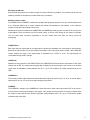
3.4 Description
General
All modules are powered by the USB so that no external power supplies are needed. The state of the module is
shown by a LED which shows an initialisation of the driver. Simple programming of the modules is done with the
support by the QLIB (Quancom driver LIBrary) which provides API-calls so that no knowledge of
driver-programming is needed. You may use the QLIB for Windows XP / 2000 / ME / 98 / Agilent VEE / LabView
and various programming languages.
6
© QUANCOM Informationssysteme GmbH
Mounting on DIN-rails
With the optional cases for the modules simple mounting to DIN-rails is possible. The modules may be used as
stationary modules in laboratories or mobile while using a notebook.
Multiple modules usable
The USBOPTO8 and USBREL8 modules are equipped with plug-able jumpers to set-up a device-address from
0 to 3. With this address up to 4 same modules are usable and detectable by the software, so the maximum
number of input and output signals raises to 32.
Additionally to the device-address the USBOPTO8 and USBREL8 provide plug-able connectors for the input and
output-signals. These connectors may be removed quickly, so that a quick change of the module is possible.
You can order these connectors separately to use this module with more than one set-up (useful for
prototyping).
USBOPTO8/LC
Each input signal is coupled with an ac-optocoupler to protect your hardware from overvoltage or wrong polarity.
Because the optocouplers are ac-optocouplers the polarity of the input-signal doesn’t matter. With a plug-able
resistor network the range of the input-voltage is adjustable from 12-30V to 5-12V. The input-signals are
connectable through fixed C-clamps.
USBOPTO8
Additional to the properties of the USBOPTO8/LC the USBOPTO8 module shows the actual state of each input
channel with a LED. The module also has plug-able C-clamps for an easy change of the module or the external
inputs. With an adjustable module-address from 0 to 3 up to four modules are usable simultaneously at the
USB.
USBREL8/LC
This module provides eight independent switch-able relais-outputs for loads of up to 15 W or 1A current. With a
switching-time of only 1ms even quick output-changes are possible.
USBREL8
The USBREL8 in addition to the USBREL8/LC shows the state of each relais-output with a LED so you have a
quick overview concerruing the states of the outputs. This module also has plug-able C-clamps to change either
the module or the external loads. With the adjustable module-address from 0 to 3 up to 4 modules are usable
simultaneously at the USB.
© QUANCOM Informationssysteme GmbH
7
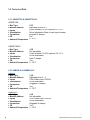
3.5 Technical Data
3.5.1 USBOPTO8 & USBOPTO8/LC
USBOPTO8
·
·
·
·
·
·
·
Bus Type
Module Address
Inputs
Visualization
Connectors
CE
Ambient Temperature
USB
Adjustable from 0 to 3
8 opto isolated (12-30V) optional 5V –12 V
Driver initialization State of each input-channel
plug-able C-clamps
Yes
0...70°C
USBOPTO8/LC
·
·
·
·
·
·
·
Bus Type
Module Address
Inputs
Visualization
Connectors
CE
Ambient Temperature
USB
Not adjustable
8 opto isolated (12-30V) optional 5V –12 V
Driver initialization
fixed C-clamps
Yes
0...70°C
3.5.2 USBREL8 & USBREL8/LC
USBREL8
·
·
·
·
·
·
·
Bus Type
Module Address
Inputs
Visualization
Connectors
CE
Ambient Temperature
USB
Adjustable from 0 - 3
8 DIL-Relais (max 15W/1A)
Driver initialization
Pluggable C-clamps
Yes
0...70°C
USBREL8/LC
·
·
·
·
·
·
·
8
Bus Type
Module Address
Inputs
Visualization
Connectors
CE
Ambient Temperature
USB
Not adjustable
8 DIL-Relais (max 15W/1A)
Driver initialization
Pluggable C-clamps
Yes
0...70°C
© QUANCOM Informationssysteme GmbH
3.5.3 USBREL8-UM
·
·
·
·
·
·
·
Bus Type
Module Address
Outputs
Visualization
Connectors
CE
Ambient Temperature
USB
Adjustable from 0 - 7 through software tool
8 changeover DIL-Relais (max 10W/1A)
Driver initialization & state of each output channel
Pluggable C-clamps
Yes
0...70°C
© QUANCOM Informationssysteme GmbH
9
3.6 Module Overview USBOPTO8 / USBOPTO8/LC
3.6.1 Setting the Module Address (JP1)
You may use up to 4 USBOPTO8 modules in one system. To let the system identify each single module, each
module has to have a unique module-address. You can set-up the module-address with JP1 as the following
table shows.
JP1
Module Address
0
1
2
3
10
© QUANCOM Informationssysteme GmbH
3.7 Visualizations of the USBOPTO8, USBOPTO8/LC
Each input has it’s own LED to show the actual state of the input-signal (not for /LC Version). Additional to the
status LEDs a configuration LED shows the modules initialization too. This LED blinks if the module is powered,
but not initialized by the driver. After initialization, the LED is lit permanently.
3.8 Technical Data of the Optocouplers
Maximum Input-Voltage
Minimum Input-Current
12-30V, 5-12V (depending to the input-resistors)
10mA
3.8.1 How to connect the Optocouplers
© QUANCOM Informationssysteme GmbH
11
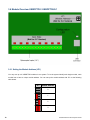
3.9 Module overview USBREL8 / USBREL8/LC
Hardware Revision 1.0
Hardware Revision 2.3
12
© QUANCOM Informationssysteme GmbH
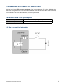
3.9.1 Connection Drawing
The following picture shows the connection of the SPST relays of the USBREL8 and USBREL8/LC.
3.9.2 Setting the Module Address (JP1)
You may use up to four USBREL8 modules in one system. To let the system identify each single module, each
module has to have a unique module-address. You can set-up the module-address with JP1 as the following
table shows.
JP1
Module Address
0
1
2
3
© QUANCOM Informationssysteme GmbH
13
3.9.3 Configure the Module Address by Software
If using Hardware revision 2.3 the module address has to be configured by software. The configuration is done
within our QLIB Configuration Utility. To use this function a QLIB version 2.4.525 and Firmware Version 1.55
or higher is required.
You will find the corresponding entry in the QLIB Configuration Utility in the tab "Device Manager" on each
module. You may expand the module and double click on the "Device" entry. Now the Properties of the module
appear where you need to navigate to the "Ressources" tab and double click on the "Device" entry again.
14
© QUANCOM Informationssysteme GmbH
Now a new window appears where you can change the address by pressing the up- and sown arrows.
Confirm every windows by pressing the "OK" button and check the successful change of the address by
reopening the QLIB Configuration Utility and check the "Dip-Switch" and "Device" values of you module.
© QUANCOM Informationssysteme GmbH
15
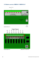
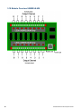
3.10 Module Overview USBREL8-UM
16
© QUANCOM Informationssysteme GmbH
3.10.1 Connection Drawing
The following picture shows the connection of the SPDT relays of the USBREL8UM.
© QUANCOM Informationssysteme GmbH
17
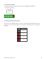
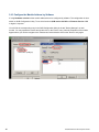
3.10.2 Configure the Module Address by Software
If using Hardware revision 2.3 the module address has to be configured by software. The configuration is done
within our QLIB Configuration Utility. To use this function a QLIB version 2.4.525 and Firmware Version 1.55
or higher is required.
You will find the corresponding entry in the QLIB Configuration Utility in the tab "Device Manager" on each
module. You may expand the module and double click on the "Device" entry. Now the Properties of the module
appear where you need to navigate to the "Ressources" tab and double click on the "Device" entry again.
18
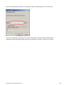
© QUANCOM Informationssysteme GmbH
Now a new window appears where you can change the address by pressing the up- and sown arrows.
Confirm every windows by pressing the "OK" button and check the successful change of the address by
reopening the QLIB Configuration Utility and check the "Dip-Switch" and "Device" values of you module.
© QUANCOM Informationssysteme GmbH
19
3.11 Visualizations of the USBREL8, USBREL8/LC
Each input has it’s own LED to show the actual state of the input-signal (not for /LC Version). Additional to the
status LEDs a configuration LED shows the modules initialization too. This LED blinks if the module is powered,
but not initialized by the driver. After initialization, the LED is lit permanently.
3.12 Technical Data of the Relays
Maximum switching load
1 Ampere / 15 Watt
Maximum switching voltage
30V DC
Switching-time (with chatter)
1ms
USBREL8 and USBREL8/LC
Maximum switching load
1 Ampere / 10 Watt
Maximum switching voltage
30V DC
Switching-time (with chatter)
1ms
USBREL8-UM
20
© QUANCOM Informationssysteme GmbH
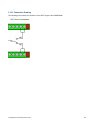
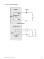
3.12.1 How to connect the Relays
USBREL8 and USBREL8/LC
USBREL8-UM
© QUANCOM Informationssysteme GmbH
21
4 Software Programming with the
QLIB
4.1 Software
4.1.1 Which Software to use?
The software to be use depends on the operating system being used and your application. To access the board,
following possibilities exist:
· Method 1: Direct I/O (access the hardware registers directly only PCI cards)
· Method 2: High-Level programming (access the board through the QLIB) is possible with the following
operating systems : Windows 7 / Vista / XP / 2000 / NT / ME / 98 / 95. You may program the hardware from
Visual Basic, Borland Delphi, Lotus Notes and other compilers or interpreters.
· Method 3: Install the QLIB for use with existing software i.e. LabView from National Instruments or Agilent
VEE from Agilent (see the samples-folder of the installation and the help to the QLIB for further information).
If you want to use Method 1 and 2 you’ll need the sources for the application. You are responsible for adding the
programming statements inside the application. For using these methods, knowledge of programming is
necessary. Chapter 4.3 ”Installation and programming with the QLIB” shows how to install and use the QLIB.
Method 3 allows you to get the QUANCOM board running with existing software, i.e. LabView or Agilent VEE.
The only thing you have to do in this case, is to install the QLIB Driver Libary from the Installation CD. For details
on installing the QLIB see chapter 4.3 ”Installation and programming with the QLIB”.
22
© QUANCOM Informationssysteme GmbH
4.1.2 QLIB: High Level Programming (Windows 7 / Vista / XP / 2000 / ME / 98)
4.1.2.1 QLIB ( QUANCOM Driver Library )
The QLIB, which stands for QUANCOM Driver LIBrary, was developed with the target to allow the simple
programming of all our data acquisition products under various operating systems. So it is easy to write an
application that runs under the operating systems Windows Me/98/95 and Windows XP/2000/NT4.0. This driver
interface is not limited to PC boards or other I/O adapters but is also targeted towards supporting the next
product generations currently being developed. The used functions and parameters are the same for all
operating systems.
Supported operating systems:
· Microsoft Windows 7 / Vista / XP / 2000 / NT 4.0 / ME / 98 / 95 und Linux
· Windows Server 2000 / 2003 / 2008
Supported compilers:
C / C++
· Borland C++ 3.1, 4.x, 5.x
· Microsoft® Visual C++ 1.x, 2.x, 4.x, 5.x, 6.x
· Microsoft® Visual C#
· Microsoft® Visual Studio 2005 / 2008 / 2010
Pascal
· Borland Turbo Pascal
Delphi
· Borland Delphi
Basic
· Microsoft® Visual Basic 3.x, 4.x, 5.x; 6.x
· Microsoft® Visual Basic.NET
© QUANCOM Informationssysteme GmbH
23
Graphical Programming Language:
· Agilent VEE® by Agilent
· LabView® by National Instruments
4.1.2.2 High-Speed Installation of the QLIB for USB
For the installation of the drivers and run time environment administrator rights are
necessary. Without the appropriate rights the driver and the run time environment cannot
be installed correctly.
Windows 7/Vista/XP/2000
Start your system
Windows ME/98
Start your system
After booting up insert driver CD and choose your
After booting up insert driver CD and choose your
language.
language.
Choose QLIB
Choose QLIB
Choose the QLIB version that correspondences to
your operating system and press install
Choose the QLIB version 1.9.8s and press install
Reboot your system
Reboot your system
After booting up connect the USB measurement
After booting up connect the USB measurement
module to the systems USB Port. It will be
module to the systems USB Port. It will be
recognized and installed automatically
recognized and installed automatically
When installing the QLIB version 1.9.8s the sample sources are already included in the
installation package.
If you want to install a newer version you will have to install the package for the sample
projects separately. The installation package is named QLIB Samples, followed by the
version number.
24
© QUANCOM Informationssysteme GmbH
5 QLIB Commands
Make sure that the QLIB (QUANCOM Driver Library) is properly installed. For further information about the
installation and how to include the necessary files in your application and how to use the QLIB functions see the
linked “QLIB” documentation.
Please
refer
the
QLIB
documentation
on
our
website:
http://www.quancom.de/manual/manual_english_qlib/qstart.htm
5.1 Programming with QLIB ( QUANCOM Driver Library )
Make sure that the QLIB (QUANCOM Library ) is installed properly and the board/module is recognized by the
QLIB-configuration-tool.
The following examples describe the usage of several commands of the QLIB to gain access to the
board/module.
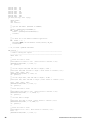
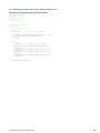
5.1.1 Examples in C for the QLIB
The following examples show how easily the QUANCOM hardware is accessed through the QLIB.
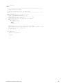
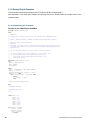
5.1.1.1 Programming in-/outputs
The text written with bold letters is important for using the QLIB in new projects. After installation of the QLIB
with examples the following sources are located inside the samples folder of the installation-path.
Example for the USBOPTO8 or USBREL8
//
//
//
//
//
//
//
//
//
//
//
//
//
//
//
//
//
//
usbmodul.cpp : Sample project for the USBOPTO8 and USBREL8 Modules
Author: Michael Reimer, QUANCOM Informationssysteme GmbH, Germany
Website: http://www.quancom.de
Product:
USB OPTO I/O Module http://www.quancom.de/qprod01/eng/pb/usbopto8.htm
USB OPTO Relay Module http://www.quancom.de/qprod01/deu/pb/usbrel8.htm
Information:
To use the QLIB Commands in your source, do the following:
(1) Add statement #include "qlib.h" to your source file.
(2) Add in the Dialog Menu->Project->Settings->C/C++->Preprocessor
"$(QLIB_INC)" to the additional include directories entry.
(3) Add in the Dialog Menu->Project->Settings->Linker->General
"$(QLIB_LIB)\qlib32.lib" to the additional library and object
modules directories entry.
#include
#include
#include
#include
#include
"stdafx.h"
"windows.h"
"qlib.h"
<conio.h>
<stdio.h>
© QUANCOM Informationssysteme GmbH
25
#define OUT1
0x1
#define OUT2
0x2
#define OUT3
0x4
#define OUT4
0x8
#define OUT5
0x10
#define OUT6
0x20
#define OUT7
0x40
#define OUT8
0x80
int main(int argc, char* argv[])
{
ULONG handle;
char ch;
char relmod=1;
//
// Open the USB Module (USBOPTO8 or USBREL8 )
//
handle = QAPIExtOpenCard(USBREL8,0);
if ( handle == 0 ) {
handle = QAPIExtOpenCard(USBOPTO8,0);
relmod=0;
}
//
// If there are no usb modules terminate application
//
if ( handle == 0 ) {
MessageBox(NULL, "No USB Modules found!","Error", MB_OK);
return FALSE;
}
// Ok, we found a QUANCOM USB Module
if (relmod) {
// ---------------------------------------------------------------------// PART 1: Setting the outputs
// ---------------------------------------------------------------------ULONG lines = 0;
//
// Reset all lines to "Low"
//
printf("Reset all lines to 'Low' ( Press return to continue ):\n");
QAPIExtWriteDO8(handle, 0, lines, 0);
ch = getchar();
//
// Set the outputs OUT2,OUT4 and OUT7 to "High" ( 8-Bit )
//
printf("Set OUT2,OUT4 and OUT7 to 'High' ( Press return to continue ):\n");
lines = OUT2 + OUT4 + OUT7;
QAPIExtWriteDO16(handle, 0, lines, 0);
ch = getchar();
//
// Set the output OUT1, OUT3 and OUT5 to "High" ( 16-Bit )
//
printf("Set OUT1, OUT3 and OUT5 to 'High' ( Press return to continue ):\n");
lines = OUT1 + OUT3 + OUT5;
QAPIExtWriteDO8(handle, 0, lines, 0);
ch = getchar();
//
// Reset line OUT3 to "Low"
//
printf("Reset line OUT3 to 'Low' ( Press return to continue ):\n");
QAPIExtWriteDO1(handle, 3 - 1, FALSE, 0);
ch = getchar();
//
// Set line OUT3 to "High"
//
printf("Set line OUT3 to 'High' ( Press return to continue ):\n");
QAPIExtWriteDO1(handle, 3 - 1, TRUE, 0);
ch = getchar();
//
// Reset all lines to "Low"
//
printf("Reset all to 'Low' ( Press return to continue ):\n");
lines = 0;
QAPIExtWriteDO8(handle, 0, lines, 0);
26
© QUANCOM Informationssysteme GmbH
ch = getchar();
} else {
// ---------------------------------------------------------------------// PART 2: Reading the inputs
//
// This part reads the state of the input lines.
// ---------------------------------------------------------------------int i;
while (!kbhit()) {
// read the current state from the inputs
lines = QAPIExtReadDI16(handle, 0, 0);
printf("\n--------------------------------------\n");
printf("Current input states\n");
printf("IN1 IN2 IN3 IN4 IN5 IN6 IN7 IN8\n");
for (i=0;i<7;i++) {
if ( lines & 1<<i) {
printf(" 1
");
} else {
printf(" 0
");
}
}
printf("\n--------------------------------------\n");
printf("Press return to stop reading the inputs every 5 seconds ...\n");
for (int j=0;(j<10) && !kbhit();j++) {
Sleep(500);
}
}
ch = getchar();
}
QAPIExtCloseCard(handle);
return 0;
}
© QUANCOM Informationssysteme GmbH
27
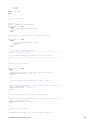
5.1.1.2 Accessing the Relais with the QLIB in C/C++
Example for accessing the relais
#include <windows.h>
#include <stdio.h>
#include <conio.h>
#include "qlib.h"
/*=====================
Main program
======================*/
void main () {
ULONG handle;
/*Handle of the USBREL8*/
if ((handle=QAPIExtOpenCard(USBREL8,0L)) == 0L) {
printf("Couldn´t open USBREL8 \n");
return;
}
for (;;) {
if (kbhit() != 0 && getch() == 27) break;
QAPIExtWriteDO8(handle,0L,0x00L,0L);
Sleep(500);
QAPIExtWriteDO8(handle,0L,0xFFL,0L);
Sleep(500);
QAPIExtWriteDO8(handle,0L,0x55L,0L);
Sleep(500);
QAPIExtWriteDO8(handle,0L,0xAAL,0L);
Sleep(500);
}
QAPIExtCloseCard(handle);
}
28
© QUANCOM Informationssysteme GmbH
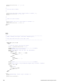
5.1.1.3 Reading the Optocoupler Inputs with the QLIB in C/C++
Example for reading the state of the optocouplers
#include <windows.h>
#include <stdio.h>
#include <conio.h>
#include ”qlib.h"
/*=====================
Main program
======================*/
void main () {
ULONG handle;
/* Handle of the USBOPTO8 */
if ((handle = QAPIExtOpenCard(USBOPTO8,0L)) == 0L) {
printf("Couldn’t open USBOPTO8 \n");
return;
}
for (;;) {
if (kbhit() != 0 && getch() == 27) break;
printf("%02lx\n",QAPIExtReadDI8(handle,0L,0L));
Sleep(500);
printf("%02lx\n",QAPIExtReadDI8(handle,0L,0L));
Sleep(500);
printf("%02lx\n",QAPIExtReadDI8(handle,0L,0L));
Sleep(500);
printf("%02lx\n",QAPIExtReadDI8(handle,0L,0L));
Sleep(500);
}
QAPIExtCloseCard(handle);
}
© QUANCOM Informationssysteme GmbH
29
5.1.2 Borland Delphi Examples
The text written in bold letters describes how to include the QLIB to a Delphi-project.
After installation of the QLIB with examples the following sources are located inside the samples folder of the
installation-path.
5.1.2.1 Programming the in-/outputs.
Example for the USBOPTO8 or USBREL8
program USBOPTO_CONSOLE_APP;
uses
WinProcs;
{*
// usbopto.pas : Sample project for the USBOPTO8 and USBREL8 Modules
//
// Author: Michael Reimer, QUANCOM Informationssysteme GmbH, Germany
//
// Website: http://www.quancom.de
// Product:
// USB OPTO I/O Module http://www.quancom.de/qprod01/eng/pb/usbopto8.htm
// USB OPTO Relay Module http://www.quancom.de/qprod01/deu/pb/usbrel8.htm
// Information:
//
// To use the QLIB Commands in your source, do the following:
//
// (1) Add statement #include "qlib.pas" to your source file.
// (2) Copy QLIB.PAS from QLIB Installation Directory
//
d:\program files\quancom\qlib32\include to your
//
working directory
*}
function KeyPressed: Boolean;
var
Buffer: TInputRecord;
Data: DWORD;
hIn: DWORD;
begin
hIn := GetStdHandle( STD_INPUT_HANDLE );
Result := False;
PeekConsoleInput(hIn, Buffer, 1, Data);
if Data <> 0 then
if Buffer.EventType = Key_Event then
begin
Result := True;
end;
FlushConsoleInputBuffer(hIn)
end;
{$APPTYPE CONSOLE}
{$INCLUDE QLIB.pas}
{$X+}
const OUT1
OUT2
OUT3
OUT4
OUT5
OUT6
OUT7
OUT8
=
=
=
=
=
=
=
=
$1;
$2;
$4;
$8;
$10;
$20;
$40;
$80;
var handle: longint;
status: longint;
relmod: integer;
lines: longint;
s: string;
30
© QUANCOM Informationssysteme GmbH
i: integer;
j: integer;
Label lab1, lab2;
begin
{*
//
// Open the USB Module
//
*}
relmod := 1;
handle := QAPIExtOpenCard(USBREL8,0);
if ( handle = 0 ) then
begin
handle := QAPIExtOpenCard(USBOPTO8,0);
relmod := 0;
end;
{*
// The handle is <> NULL if there is a USB Module installed
*}
if ( handle = 0 ) then
begin
s := 'No QUANCOM USB Module found!';
writeln(s);
halt(0);
end;
{*
//
//
//
//
//
//
*}
Ok, we found a QUANCOM USB Module
-----------------------------------------------------------------------PART 1: Setting the outputs
The following constants can be used to program the outputs:
------------------------------------------------------------------------
{*
//
// Reset all lines to "Low"
//
*}
if ( relmod = 1 ) then
begin
lines := 0;
writeln('Reset all lines to Low ( Press return to continue ):');
QAPIExtWriteDO8(handle, 0, lines, 0);
Readln;
{*
//
// Set the outputs OUT2,OUT4 and OUT7 to "High" ( 8-Bit )
//
*}
writeln('Set OUT2,OUT4 and OUT7 to High ( Press return to continue ):');
lines := OUT2 + OUT4 + OUT7;
QAPIExtWriteDO8(handle, 0, lines, 0);
Readln;
{*
//
// Set the output OUT1, OUT3 and OUT5 to "High" (8-Bit )
//
*}
writeln('Set OUT1, OUT3 and OUT5 to High ( Press return to continue ):');
lines := OUT1 + OUT3 + OUT5;
QAPIExtWriteDO8(handle, 0, lines, 0);
Readln;
{*
//
// Reset line OUT5 to "Low"
//
*}
writeln('Reset line OUT5 to Low ( Press return to continue ):');
© QUANCOM Informationssysteme GmbH
31
QAPIExtWriteDO1(handle, 5 - 1, 0, 0);
Readln;
{*
//
// Set line OUT5 to "High"
//
*}
writeln('Set line OUT5 to High ( Press return to continue ):');
QAPIExtWriteDO1(handle, 5 - 1, 1, 0);
Readln;
{*
//
// Reset all lines to "Low"
//
*}
writeln('Reset all to Low ( Press return to continue ):');
lines := 0;
QAPIExtWriteDO8(handle, 0, lines, 0);
Readln;
end;
else
begin
{*
// -----------------------------------------------------------------------// PART 2: Reading the inputs ( and detect changed inputs )
//
// This part reads the state of the input lines.
// -----------------------------------------------------------------------*}
while Not KeyPressed do
begin
{*
// read the current state from the inputs
*}
lines := QAPIExtReadDI8(handle, 0, 0);
write(#13#10'--------------------------------------'#13#10);
write('Current input states'#13#10);
write('IN1 IN2 IN3 IN4 IN5 IN6 IN7 IN8'#13#10);
for i:=0 to 7 do
begin
if lines AND ( 1 shl i) <> 0 then
begin
write(' 1
');
end
else
begin
write(' 0
');
end
end;
write(#13#10'--------------------------------------'#13#10);
write('Press return to stop reading the inputs every 5 seconds ..'#13#10);
for j:=0 to 10 do
begin
Sleep(500);
If KeyPressed then
goto lab1;
end;
end;
end;
lab1:
writeln(#13#10'Ready ! Press a key to continue !');
ReadLn;
QAPIExtCloseCard(handle);
32
© QUANCOM Informationssysteme GmbH
end.
© QUANCOM Informationssysteme GmbH
33
6 Annex
6.1 Frequently asked Questions
· How can I identify my board/card when using more than one of the same type in a system?
• Most of our modules and cards may be configured using the onboard dip switch, please see the
corresponding manual for more
information.
• If there is nor dip switch on your board, the address may be configured software sided by using our
addressing tool which can be
downloaded
here
-->
http://www.quancom.de/qprod01/eng/files/download.adress_changer.zip/$file/Adress_Changer.zip.
· What is the maximum frequency of QUANCOM USB modules when using the QLIB?
• One function call out of the QLIB takes about 2ms - 4ms, which results in a frequency of 500Hz to
250Hz.
• The frequency always depends on the current free system capacity.
· How am I able to read back the status of the outputs?
• Use the QLIB function QAPIExtSpecial with the jobcode JOB_READ_BACK_RELAYS
· Why is the ”Control Panel” board configuration dialog ”QLIB” empty?
• There is no QUANCOM PCI or USB board in the system.
• There are no drivers installed for a QUANCOM ISA board.
· I get the message ”QLIBNDRV.SYS not found ”or ”QLIBNDRV.VXD not found” after installation. What
can I do?
• Check that the QLIB is installed properly. For further information about the installation process and the
general
programming with the QLIB please see the “QLIB” manual which is included on the installation CD.
• If you use a QUANCOM ISA board check if the drivers for the QUANCOM board are installed.
· Why do I get the message "Driver QLIBNDRV.SYS” or ”Driver QLIBNDRV.VXD” could not be loaded?
• Check that the QLIB is installed properly. For further information about the installation process and the
34
© QUANCOM Informationssysteme GmbH
general programming with the QLIB
please read the “QLIB” manual which is included on the installation
CD.
• The driver for the QUANCOM board was not loaded. (Control Panel => System)
· Windows 7/Vista/XP/2000/NT: Does the QLIB have to be installed with administrative privileges?
• The QLIB always has to be installed with administrative privileges.
· Windows 7/Vista/XP/2000/NT: Why do I get the message ”Driver could not be installed” during the
installation?
• Installation was made without administrative privileges
• The Installation media is corrupt
· Windows 7/Vista/XP/2000/NT: Why do I get the message "Driver QLIBNDRV.SYS could not be loaded”
?
• The driver’s installation has failed, because the QLIB was not installed with administrative privileges
• QLIB-Software was installed on a network drive. Always install the QLIB on a local drive.
· Windows 7/Vista/XP/2000/NT: How can I manually install the driver QLIBNDRV.SYS?
If the QLIBNDRV.SYS failed to install, it may be necessary to install the driver manually.
Please take the following steps to install the driver manually:
· Search on the installation CD ”Tools” for the tool instdrv.exe in the directory. With this tool you can install and
de-install the driver manually.
· Please call this tool with the following command line parameters:
instdrv libndrv d:\directory\qlibndrv.sys .
(Replace d:\directory with the drive, where the driver qlibndrv.sys is located.)
· Go to ”Start -> Settings ->Control panel ->(Administrative Tools / Windows 2000 only) -> Drivers” change the
start type to ”Automatic”, then click on the ”Start” button. Please restart the system for the changes to become
active.
· Why do I have to restart the driver after every reboot?
The starting type of the driver is set to ”Manual”. If you wanted to you are able change this setting on “Automatic”
to start the driver on every reboot of the system.
© QUANCOM Informationssysteme GmbH
35
6.2 Customer Communication and Help
Do you need help?
If you don’t know how to go on during the installation or
operation of your QUANCOM board please consult this user’s
guide first.
! Tip !
In the chapter “Frequently asked question” there are a lot of
answers to questions for known problems. They may help you to
solve your problems. You can find an ASCII – text – file
README.TXT, which includes changes made after printing of
this user’s manual on the QUANCOM installation CD.
! Important !
If you have further questions please contact our support team.
For this case please prepare the following information:
· Exact type of the board.
· Version of the driver
· Version of the QLIB
· Operating system, hardware equipment and bus system
· Name and version of the program, which reports
the failure
· A detailed failure description. To make sure,
please try to reproduce the failure, and describe
exactly, which steps led to this failure.
36
© QUANCOM Informationssysteme GmbH
Contact ?
The QUANCOM internet website
www.quancom.de
Per Fax
+49 22 36 / 89 92 - 49
Per E-Mail:
[email protected]
Address:
QUANCOM INFORMATIONSSYSTEME GmbH
In der Flecht 14
50389 Wesseling
Germany
Quancom Hotline Germany:
0 22 36 / 89 92 - 20
Monday - Thursday
9:00 - 18:00
Friday
9:00 - 17:00
Actual drivers
You can find the latest version of QUANCOM
software on our internet website www.quancom.de.
You can also find a lot of information and “Frequently
asked questions (FAQ’s)” there., please check if you
are using the latest software version of the
QUANCOM software before contacting the
QUANCOM support.
Reparatur
If you are not sure whether your QUANCOM board
is defective please call the QUANCOM Hotline:
Tel.: +49 22 36 / 89 92 – 20
Before sending us the QUANCOM board to be
repaired call:
Tel.: +49 22 36 / 89 92 – 20
© QUANCOM Informationssysteme GmbH
37
If you send your QUANCOM board to us, please use
original package or any other suitable package, to
protect the contents against transport damage. You
also need to send us a copy of the original bill and
the RMA number.
38
© QUANCOM Informationssysteme GmbH
6.3 Technical Support Form
If you have internet access please enter the following URL in your browser:
http://www.quancom.de/quancom/qshop.nsf/techniksupport?OpenForm&deu
else optocopy this form and use the copy of this form as a reference for your current
configuration. Complete this form before contacting QUANCOM Informationssysteme GmbH
for technical support help and our applications engineers may answer your questions more
efficiently. If you are using any other QUANCOM hardware or software products please add
them to this configuration form. Include additional pages if necessary.
Name:
______________________________
Company:
______________________________
Address:
______________________________
Phone:
______________________________
Fax:
______________________________
Computer brand / Processor:
______________________________
Operate system:
______________________________
Display adapter:
______________________________
Mouse:
______________________________
QUANCOM board
______________________________
Other adapters installed:
______________________________
Hard disk (capacity, free):
______________________________
The Problem is:
______________________________
List any error messages:
______________________________
______________________________
______________________________
The following steps will reproduce the problem:
______________________________
______________________________
______________________________
______________________________
______________________________
© QUANCOM Informationssysteme GmbH
39
6.4 Feedback Form
QUANCOM Informationsysteme GmbH would like you to comment on the documentation supplied with our
products. This information helps us to provide you with quality products to meet your needs. Include additional
pages if necessary.
Titel:
USBREL8 / USBOPTO8 / USBREL8-UM
Erstellungsdatum:
13.12.2012
Name:
________________________________________________
Company:
________________________________________________
Address:
________________________________________________
Phone:
________________________________________________
Fax:
________________________________________________
Comment:
________________________________________________
________________________________________________
________________________________________________
________________________________________________
________________________________________________
40
Mail to:
[email protected]
Fax to:
+49 2236 89 92 49
Address:
QUANCOM Informationssysteme GmbH
In der Flecht 14
50389 Wesseling
Germany
© QUANCOM Informationssysteme GmbH
6.5 Hard- and Software Configuration Form
This form allows you to record the settings of your hardware and software. Complete this form each time you
revise your software or hardware configuration, and use this form as a reference for your current configuration.
Completing this form accurately before contacting QUANCOM Informationssysteme GmbH for technical support
helps our application engineers answer your questions more efficiently.
· QUANCOM Product:
Name / Name of board
__________________________________
Interrupt Level
__________________________________
DMA Channel
__________________________________
Basis I/O Address
__________________________________
Operate system
__________________________________
· Other Information
Computer Model
__________________________________
Processor
__________________________________
Clock Frequency
__________________________________
Type of Video board installed
__________________________________
DOS Version
__________________________________
Programming Language
__________________________________
Programming Language Version
__________________________________
· Other Boards in System
Basis I/O-Address of other boards
__________________________________
DMA Channels of other boards
__________________________________
Interrupt Level of other Cards
__________________________________
© QUANCOM Informationssysteme GmbH
41
6.6 Trademarks
Linux is registered trade-mark of Linus Torvalds.
MS, MS-DOS, Microsoft, Visual Basic, Windows, Windows Vista/XP/2000/NT/ME/98/95 is registered trade-mark
of Microsoft Corporation.
XT and PS/2 are trade-marks and IBM, OS/2 and AT are registered trade-mark of International Business
Machines Corporation.
Intel, Pentium is registered trade-mark of Intel Corporation.
USB is registered trade-mark of USB Implementers Forum Inc.
JAVA is registered trade-mark of Sun Microsystems.
DELPHI and Pascal are registered trade-mark of Borland Corporation.
PCI is registered trade-mark of PCI Special Interest Group.
PCI is registered trade-mark of PCI Special Interest Group.
National Instruments, LABVIEW is registered trade-mark of National Instruments Corporation.
Agilent VEE is registered trade-mark of Agilent Technologies.
By other product- and company names, that are mentioned in this manual, it may deal with trademarks of the
respective owners.
42
© QUANCOM Informationssysteme GmbH