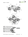
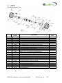
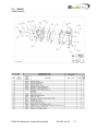
1
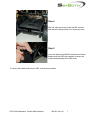
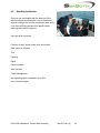
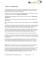
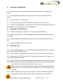
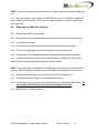
Addendum
Crawler Skid Assembly
(CSA301)
DOCS-045
Rev B
The information, photographs, illustrations and descriptions contained in this manual are the property of
SeaBotix Inc. Unauthorized duplication and distribution is strictly forbidden. Additionally, SeaBotix Inc.
reserves the right to alter any and all information contained in this manual.
Head Office: SeaBotix Inc., 2877 Historic Decatur Road STE 100, San Diego, CA 92106 USA +1 (619) 450-4000
Australia Office: SeaBotix Inc. Australia Pty Ltd.8A Sparks Road, Henderson, WA 6166, Australia +61 (0)8 9437-5400
© 2009 by SeaBotix, Inc. All Rights Reserved
Table of Contents
PAGE
Section 1:
Section 2:
2.1
2.2
2.3
2.4
2.5
2.6
2.7
2.7.1
2.7.2
2.7.2
2.7.4
Section 3:
3.1
3.2
3.2.1
3.2.2
3.2.3
3.3
3.4
Section 4:
4.1
4.2
4.3
4.4
4.5
4.6
4.7
4.8
4.9
Section 5:
5.1
5.2
Purpose ......................................................................................................4 Potential Hazards .......................................................................................4 Testing .......................................................................................................5 Attaching the CSA301 Crawler Skid Assembly .....................................6 Pre-Dive Inspection and System Test ....................................................8 Inspection ...................................................................................................8 Testing system ...........................................................................................8 Deployment ................................................................................................9 In-water testing.........................................................................................10 Maneuverability ........................................................................................11 Releasing trapped air .................................Error! Bookmark not defined. Trimming for Neutral Buoyancy................................................................12 Factors to Consider When Trimming the LBC: ........................................12 Trimming the system when attaching the Crawler Skid. ..........................12 Adjusting the Metacenter of Buoyancy.....................................................13 Post Dive Inspection ................................................................................14 LBC Controls ..........................................................................................15 Operator Control Unit ...............................................................................15 Joystick ....................................................................................................15 ROV Mode (with or without skid attached) ...............................................15 Attach Mode (skid attached) ....................................................................16 Crawler Mode (skid attached) ..................................................................16 Proportional Vertical Thruster Control Knob ............................................16 Membrane Keypad ...................................................................................16 Operating the LBC .................................................................................18 Operating Environment ............................................................................18 The Tether................................................................................................18 Piloting .....................................................................................................19 Crawler Mode ...........................................................................................20 Technique for attachment ........................................................................21 Detachment ..............................................................................................22 Practice ....................................................................................................22 Watching LBC ..........................................................................................22 Watching Monitor .....................................................................................23 Maintenance ...........................................................................................24 After each use ..........................................................................................24 Every 50 hours .........................................................................................24 DOCS-045 Addendum, Crawler Skid Assembly
(Rev B 6 Jan 10)
2
Section 6: 6.1
6.2
6.3
6.4
Section 7: 7.1
7.2
7.3
Troubleshooting .....................................................................................25 Replacing the VRAM Plate.......................................................................26 Replacing the VRAM Shroud ...................................................................26 Replacing a tire. .......................................................................................26 Replacing the Shaft Flex Coupling. ..........................................................27 Parts List .................................................................................................28 DMA301 ...................................................................................................29 DMA302 ...................................................................................................30 VRA301 ....................................................................................................31 Glossary of Abbreviations and Terms ......................................................32 Warranty...................................................................................................37 Shipping Charges.....................................................................................37 Return Policy ............................................................................................37 DOCS-045 Addendum, Crawler Skid Assembly
(Rev B 6 Jan 10)
3
IMPORTANT…
Read this manual prior to operation.
Purpose
The purpose of this manual is to provide LBC operators with a clear understanding of proper and
safe operating procedures. It is a valuable reference tool and should be thoroughly reviewed
prior to operation of the LBC. If any part of this manual regarding the use of the LBC is unclear
or not thoroughly understood, please contact SeaBotix Inc. or any authorized distributor for more
detailed information.
Before operating the LBC, it is important to read this manual thoroughly to understand the proper
use and precautions required for its safe operation. Throughout this manual information of
special interest is highlighted with the following symbols. Be sure to read and understand each
of these important messages.
NOTE: Information marked with this symbol is designed to help with the operation of
LBV by providing additional useful operating tips or facts.
CAUTION: This symbol indicates a potential for harm and special care must be
taken.
Potential Hazards
Although the LBC is a safe and reliable tool when used and cared for properly, there are certain
inherent safety hazards associated with the operation of the LBC that should be reviewed and
avoided. SeaBotix Inc., and its distributors, associates, and affiliates, cannot be held liable for
any damages, injuries, losses or problems whatsoever resulting from negligent operation, or an
LBC system that has been altered or modified without prior written consent from SeaBotix Inc.
Thruster Propellers
Keep the propellers clear of obstructions at all times.
Do not put fingers or other objects near the propellers at any time.
Be careful with any loose clothing, jewelry, etc.
DOCS-045 Addendum, Crawler Skid Assembly
(Rev B 6 Jan 10)
4
Electrical Shock
The LBC operates at high voltages that can cause injury and/or death.
Keep the Surface Power Supply plug away from the water.
Check all plugs for the presence of water prior to connecting.
If the system is cut, chafed, or otherwise damaged, do not operate the vehicle.
Do not open the vehicle housing when the power is on.
Testing
Each LBC system is carefully manufactured to ensure long term safe operation. Prior to
shipment every LBC is tested for proper operation, including pressure testing to full operating
depth. Should a defect be found contact SeaBotix Inc., or an authorized distributor immediately.
Design and Documentation Changes
SeaBotix Inc., reserves the right to make changes to the specifications of the LBC and/or alter
any documentation at any time, without notice, or may alter any or all documentation without
notice.
DOCS-045 Addendum, Crawler Skid Assembly
(Rev B 6 Jan 10)
5
Section 1: Attaching the CSA301 Crawler Skid Assembly
NOTE: Disconnect the tether from the LBV prior to performing this procedure.
NOTE: Refer to DOCS-062 Addendum Crawler Trimming Instructions for specific
trimming instructions prior to performing this step.
Step 1
Unplug the Crawler Skid Control Cable from the
blanking plug attached to the crawler skid located on
the LBV bumper frame port side.
Step 2
Remove the ballast weights as listed in Section
2.7.2.2 of this manual, and store them in a safe
location. The weights will be required to re-trim your
LBV when the crawler skid is removed.
Step 3
Place the LBV on the crawler skid assembly and
connect the cable to the connector on the front axle
assembly.
Tighten the locking sleeve.
The easiest way to connect the CSA301 to the LBV is
to pivot the LBV off of the rear section of the bumper
frame and hold the front of the LBV up.
NOTE: Lubricate the male pins of the connectors with
grease GLA001.
NOTE: Be sure to align the pins on the connector.
The small silver pin is a guide pin only.
DOCS-045 Addendum, Crawler Skid Assembly
(Rev B 6 Jan 10)
6
Step 4
With the cable connected, lower the LBV onto the
skid assembly being careful not to pinch any wires.
Step 5
Insert and tighten eight M6x20 stainless steel button
head screws with M6 nylon washers to secure the
crawler skid assembly to the LBV frame.
To remove the crawler skid from the LBV, reverse this procedure.
DOCS-045 Addendum, Crawler Skid Assembly
(Rev B 6 Jan 10)
7
Section 2: Pre-Dive Inspection and System Test
Before placing the LBV into the water, it is important to ensure that all systems operate as they
are supposed to. This process should be done each time the LBC is operated and will only take
a moment to perform.
2.1
Inspection
Visually look over the LBC for obvious damage. Look at the wheels, floatation, cables, etc. for
damage.
2.2
Testing system
For this portion, the CSA301 Crawler Skid Assembly must be attached to the LBV. The full
system must be connected and powered on. Refer to the system Operators manual for proper
set up.
DOCS-045 Addendum, Crawler Skid Assembly
(Rev B 6 Jan 10)
8
Crawler skid assembly
Press the Auto Heading switch to cycle through the modes. (Attach, Crawl, ROV.)
In the Attach mode, press the “DEPTH” button to ensure that the VRAM suction device
turns on and off.
In the attach mode, move the joystick laterally to verify that the the vertical thrusters and
not the lateral thruster are activated.
In crawler mode, verify that the wheels move forward and back. To perform this test,
place the LBC assembly on a set of blocks that will keep the wheels suspended, or
place the LBC on its top. Use the joystick to confirm that the wheels turn to enable the
skid to move forward, reverse, turn left and turn right.
NOTE: Do not operate the wheels while on a hard
surface out of the water as it may damage the wheel
couplings.
2.3 Deployment
With all systems checked and in operational condition, the LBC is ready for deployment. When
deploying the LBC, locate a suitable location that allows a clear path to the water. Establish a
firm footing and lower the LBC into the water using the tether.
Make sure that you are lowering the LBC into a spot that does not have immediate dangers such
as wiring, rope or rocks.
NOTE: Never allow the tether to run over sharp edges or exceed the minimum bend
radius of 150mm (6 in.). Allowing the tether to run over sharp edges or exceed the
minimum bend radius of 150mm (6 in.) may result in damage to the tether. It is a good
practice to use material such as carpeting, a towel or other soft pliable material as
protection under the tether at the edge of a dock, ships edges or railings, etc.
DOCS-045 Addendum, Crawler Skid Assembly
(Rev B 6 Jan 10)
9
NOTE: With the crawler skid assembly attached, remember that the LBV’s weight is
considerably increased. It is suggested that the QRS001 Quick Recovery System be
used.
Caution: As it is designed to reduce friction, the tether can be slippery when wet and
care must be exercised during deployment and retrieval to prevent damage to the
tether or injury to personnel.
NOTE: The LBC is designed for use in the water and it requires water for cooling.
In addition, the wheels are not designed for operation on a hard surface out of the
water. Attempting to drive the LBC when out of the water may result in damage to the
flex couplings.
2.4
Releasing trapped air
Once the LBC is in the water, you must make sure that the LBC maneuvers correctly. Any
trapped air must be released from the LBV to verify and maintain neutral buoyancy.
DOCS-045 Addendum, Crawler Skid Assembly
(Rev B 6 Jan 10)
10
2.5
Maneuverability
Use the joystick to move the LBC in all horizontal directions to ensure that it is responding
promptly and correctly.
For example: When you move the joystick forward, the LBV should move forward, without
rotating or moving laterally.
Operate the vertical thruster control knob to test for proper dive and surfacing operation.
DOCS-045 Addendum, Crawler Skid Assembly
(Rev B 6 Jan 10)
11
2.6
Trimming for Neutral Buoyancy
During the in water testing, if the LBC is not neutrally buoyant then an adjustment of the lead
ballast is required. Take the time to ensure that the buoyancy of the LBC is as close to neutral
as possible. By making the buoyancy of the LBC as close to netural as possible will make
operating the LBC easier by not requiring constant adjustment to maintain the desired depth.
Adjust the trim so that the LBC sits level both fore and aft and port and starboard.
2.6.1 Factors to Consider When Trimming the LBC:
2.6.1.1 Salinity: A change of just a few parts per thousand in salinity will have a
dramatic effect on the buoyancy of the LBC, i.e., if the LBC is trimmed for neutral
buoyancy in 35ppt salt water, and then operated in 32ppt, it will be noticeably negatively
buoyant. Experience shows that this difference (of just 3ppt) will result in about a 2m per
minute unaided descent rate.
2.6.1.2 Temperature: Temperature has a lesser effect on the trim of the LBC but
changes of 10C or greater will have a noticeable effect. An LBC trimmed for neutral
buoyancy in 5C water then placed in 25C water will be negatively buoyant. This will not
be as significant as the 3ppt salinity change listed in 2.7.1.1 above but the difference will
be noticeable.
Remember: Anything that changes the density of the water will affect the trim of the
LBC!
In the crawler mode the trim must also take into account the “metacenter” of buoyancy. If the
metacenter is not properly adjusted, the LBC will be difficult to attach to the inspection area.
2.6.2 Trimming the system when attaching the Crawler Skid.
Supplied with the Crawler Skid are 4 additional Syntactic Foam Floatation Modules (FLK300)
that are required to re-trim the system once the Crawler Skid is attached, converting the system
from and LBV to a LBC.
Please refer to DOCS-062 Addendum Crawler Trimming Instructions for specific instructions for
trimming the system after attaching the Crawler Skid.
DOCS-045 Addendum, Crawler Skid Assembly
(Rev B 6 Jan 10)
12
MA253
MA254
MA255
Crawler Skid, Port Forward.
Crawler Skid, Port Aft
Crawler Skid, Starboard Aft.
Attaches with 1 ea FN394
Attaches with 1 ea FN394
Attaches with 1 ea FN394
M5 x 30 Button Head
M5 x 30 Button Head
M5 x 30 Button Head
MA256 Float, Crawler Skid, Cross Bar
Attaches with 2 ea FN386 M6 x 16 Button Head
2.6.2
Adjusting the Metacenter of Buoyancy.
The LBV is shipped pre-trimmed for neutral buoyancy. This manual (Section 4) contains the
trimming changes required when attaching the CSA301 (Crawler Skid Assembly).
During the in water maneuvering test, keeping the LBC below the surface of the water will assist
in releasing any air trapped on the exterior of the LBC during deployment.
Once the LBC with the CSA301 attached is trimmed for neutral buoyancy, per Section 4, the
metacenter must be tested and adjusted for proper operation.
Place the assembled LBC with the tether attached into the water matching the salinity
and temperature of the water where it will be operated.
Reach down and grab the lower frame of the CSA301 and rotate the LBV on its
longitudinal axis. (NOTE: This is a subjective test so some experimentation will be
required.)
The LBC should roll easily to the full inverted position and once released, roll gently back
to the float up position. If the LBC rolls back very quickly, or it remains in the inverted
position for any period of time, additional trimming will be required.
DOCS-045 Addendum, Crawler Skid Assembly
(Rev B 6 Jan 10)
13
If the LBC rolls very quickly back into position, either the weight needs to be repositioned
closer to the top of the LBC or added floatation needs to be placed closer to the bottom
of the LBC.
If the LBC remains inverted, the weight needs to be moved towards the bottom of the
LBC.
What you are trying to accomplish here is to move the metacenter (center of buoyancy) towards
the vertical center of the LBC. If the separation of weight vs. buoyancy is spread too far in the
vertical axis, the LBC will not want to roll when attempting to attach to your survey target. If the
separation of weight vs. buoyancy is too close together, the LBC will be unstable and difficult to
control.
2.6.4
Post Dive Inspection
After each use of the LBC, it is important to visually inspect the LBC for any damage that may
have occurred, such as any obstructions around the thrusters, or other indications that
maintenance or repairs are required.
Check:
The tether for cuts or damage
The thrusters for obstructions (fishing line, rope, seaweed, etc.)
The view port for scratches
Visually check the entire LBC for any other signs of damage
DOCS-045 Addendum, Crawler Skid Assembly
(Rev B 6 Jan 10)
14
Section 3: LBC Controls
The LBC has been designed to be simple and intuitive to operate. A new operator should find
that after reading this manual and an hour or so of hands on use, operating the LBC is quite
easy. Using the tips in this manual will help you to become a proficient and confident LBC
operator.
3.1
Operator Control Unit
The operator control unit (OCU)
controls the operation of the LBC. This
section will help to explain the function
of each key and when it should be
used. When first learning to operate
the LBC, spend time with the LBC at
the surface where you can readily see
how the commands affect the LBV.
Holding the control console correctly
will help control the LBC. The recommended method is to hold the operator control unit in both
hands, with the left hand using all fingers to support the console, and the thumb resting on the
vertical thruster knob. Place the right hand in such a way that the forefinger and thumb hold the
top of the joystick and the other three fingers support the console. You may prefer to place the
console on a flat surface if available and stable.
3.2
Joystick
The joystick has different functions depending on which mode the LBV is in (whether or not the
crawler skid assembly is attached).
3.2.1
ROV Mode (with or without skid attached)
Pushing the joystick forward moves the vehicle in the forward direction. Pulling the joystick
backwards moves the vehicle in the reverse direction. Moving the joystick laterally moves the
vehicle in the respective lateral direction. Rotating the upper portion of the joystick rotates the
vehicle’s heading to port or to starboard.
DOCS-045 Addendum, Crawler Skid Assembly
(Rev B 6 Jan 10)
15
3.2.2
Attach Mode (skid attached)
With the crawler skid attached and the Attach mode selected, the lateral function of the joystick
changes. Rather than moving the LBC laterally, movement of the joystick causes the LBC to
roll. This function is to enable the LBC to attach to hard surfaces for crawler mode operations.
3.2.3
Crawler Mode (skid attached)
With the crawler skid attached and in the crawler mode, the joystick is used to drive the wheels
of the crawler skid instead of the thrusters of the LBC. Pushing forward moves the LBC forward,
pulling back moves the LBC in reverse and rotate turns the LBC. Lateral movement of the
joystick has no function in the crawler mode.
3.3
Proportional Vertical Thruster Control Knob
Located on the front left side of the control console is the vertical
thruster control knob. Positioning your left thumb on top of the
knob
will allow you to easily rotate the knob. Rotating the knob forward
causes the LBC to surface and, conversely, rotating the knob
backward causes the LBC to dive. If the operator desires this
feature to operate in the rotate forward to dive, and rotate aft to surface, that feature can be
changed by referring to the Options menu section found in the LBV User’s Manual.
The control knob is variable and has a center detent to turn the vertical thruster off. Ensure that
the vertical thruster is off prior to removing the LBC from the water.
3.4
Membrane Keypad
AUTO HEAD
The “HEAD” button has a different function when the crawler skid assembly is
attached.
Crawler Skid Attached
The “HEAD” button is used to change modes on the LBV and is directly related to operating the
LBV in crawler mode on a hard surface. By default the LBV with the crawler skid attached
powers up in the ROV Mode. When the “HEAD” button is pressed once, the mode is changed to
Attach mode. When the “HEAD” button is pressed again, the mode is changed to crawler mode.
Pressing the “HEAD” button again changes the mode back to the ROV mode.
Note: See page 14 section 4 (“Operating the LBC”) for more information on the
different modes and their functions.
DOCS-045 Addendum, Crawler Skid Assembly
(Rev B 6 Jan 10)
16
AUTO DEPTH
The “DEPTH” button, like the “HEAD” button, has a different function when the
crawler skid assembly is attached.
Crawler Skid Attached
The “DEPTH” button allows the operator to turn the VRAM suction device on and off.
ACCESSORIES
When the crawler skid assembly is installed, the “ “ button decreases the
VRAM attraction and the “ “ button increases the attraction.
DOCS-045 Addendum, Crawler Skid Assembly
(Rev B 6 Jan 10)
17
Section 4: Operating the LBC
4.1
Operating Environment
As simple as the LBC is to operate, there are several points to keep in mind. To help focus on
the task, a comfortable operating environment will help greatly. Find a suitable area with a
comfortable place to sit and stay relaxed. Take the time to route the cabling in a way as to stay
untangled without posing a tripping hazard. Place the monitor, on a secure stable platform, at
eye level whenever possible which will help reduce neck fatigue.
4.2
The Tether
A key feature to the LBC performance is the small diameter tether. By reducing the size of the
tether, drag is greatly reduced thus enabling the LBC to operate in strong currents or with longer
lengths of cable in the water. Because of its small size and light weight managing the tether is
simple.
The tether is neutrally buoyant in fresh water and slightly positively buoyant in seawater.
Pay attention to the turns counter on the video overlay to keep the tether as straight as possible.
DOCS-045 Addendum, Crawler Skid Assembly
(Rev B 6 Jan 10)
18
Prior to connecting the underwater connector to the LBC, put a small amount of Gel Lube, (use
GLA001 which is provided with your order), on your fingers and lubricate the male pins. This will
help with installation and offer protection from water and corrosion.
Note: Never exceed the minimum 150mm (6in) bend radius.
Note: Never exceed the maximum safe working load of either 45kg (100lbs) or100kg
(220lbs) depending on the tether supplied with your system.
4.3
Piloting
All movement of the LBC is done through the operator control unit that is ergonomically designed
to fit comfortably in the operator’s hands. The vehicle User’s Manual describes the function of
each button. Taking the time to understand these functions will help the operator quickly
develop an intuitive feel for the LBV’s response in the water.
There are many different things to consider when operating the vehicle. The more in tune you
are with the system equipment and the working environment the more successful you will be.
Here are a few helpful tips to consider:
Make sure everything is setup properly tested before putting the vehicle into the water.
Practice regularly. There is nothing worse than not using the vehicle for a while and forgetting
some of the controls and/or their functions.
Focus on smooth maneuvers. Thruster gain settings can help with this.
Get a competent assistant that knows how to manage the tether.
Don’t be afraid to surface the vehicle and start over if
you get disoriented.
As with any ROV, the primary application is to gather
high quality video footage. When operating the vehicle
on site, the operator will typically not be able to see the
vehicle, only the video.
DOCS-045 Addendum, Crawler Skid Assembly
(Rev B 6 Jan 10)
19
4.4
Crawler Mode
The unique LBC, with its attached crawler skid, is also simple to operate. It does require a bit
more practice to attach the LBC to a non-horizontal hard surface, but once mastered this ability
becomes a valuable asset for stable and precise inspections.
There are some other helpful techniques when operating the LBC in the crawler mode.
Deployment can be done from the ship (if performing a hull inspection) or a dock near the
surface to be inspected (including a ship). Keep your tether placement in mind for ease of
deployment as you position yourself.
Whenever possible, it is easier to attach the LBC to a ship hull or hard surface when watching
the monitor rather than directly observing the LBC. Don’t be afraid to set yourself up for the
easiest method of operation.
When attached to a hard surface such as a hull, it is possible to drive to various objects or areas
of interest and stop. The operator can then focus on the best camera angles without worrying
about losing sight of the target.
The LBV with the crawler skid attached drives much like a tank and pivots off its center axis.
Operators will quickly learn that in the crawler mode the stability is amazing and the ability to
maneuver into tights spots is simple. An experienced operator will be able to conduct a full hull
survey in a short period of time with greater accuracy and quality than using an ROV.
Navigation on a ship hull or hard surface is best accomplished by finding a reference mark such
as a weld line or seam. In this regard, a ship’s plan can be very useful.
DOCS-045 Addendum, Crawler Skid Assembly
(Rev B 6 Jan 10)
20
4.5
Technique for attachment
Follow these basic steps to attach the LBC with the crawler skid assembly to a ship’s hull.
Step 1
Pilot the LBC toward the hull and, when close, maneuver the LBC parallel to the ship. Use
the lateral thruster to push the LBC against the hull.
NOTE: The easiest point to attach to is the most vertical surface which is typically
amidships to aft.
Step 2
Press the “HEAD” button on the operator control unit to switch from ROV mode to Attach
mode. An “A” will appear on the lower right corner of the video overlay.
Step 3
Now that you are in the Attach mode, the lateral control on the joystick will roll the LBC.
Move the joystick laterally to roll the LBC as needed to match the angle of the hull.
A small amount of down thrust is recommended to help keep the LBC pushed against the
hull.
Step 4
Once the LBC is parallel to the hull, press the “DEPTH” key to turn on the VRAM attachment
device. This will attach the LBC to the hull.
Step 5
With the LBC attached, press the “HEAD” button again to enable the drive mode and to
disable the thrusters. A “C” will appear to let you know that you are in crawler mode
as will the odometer display that will appear on the monitor.
DOCS-045 Addendum, Crawler Skid Assembly
(Rev B 6 Jan 10)
21
4.6
Detachment
When the survey is finished press the “HEAD” button to switch to ROV mode prior to turning off
the VRAM attachment device. By switching to ROV mode you are controlling the thrusters right
away and reducing the risk of drifting into a hazard.
Tips
Timing is the key to a successful operation.
Do not roll the LBC too fast.
Do not turn the VRAM on too soon or the LBC will torque due to the force created by the VRAM.
Try to use the wheels as a pivot point whenever possible.
Make sure that you are close to the hull before rolling the LBC to a parallel alignment.
NOTE: AUTO heading and depth buttons are disabled and assigned different functions
when the crawler skid assembly is attached.
4.7
Practice
Before using the vehicle in a work environment, it is
recommended that you practice in still clear water. A
swimming pool is an ideal location for practice. Such a
protected environment allows you to focus on training
rather than keeping the vehicle out of trouble.
4.8
Watching the Vehicle
Initially operate the vehicle in the swimming pool where you can see it respond to your
commands. Spending time practicing in this manner will help you to intuitively know how the
vehicle responds when you cannot see it. For example, you will have a better idea of how fast
the vehicle is moving in relation to the position of the joystick at a certain gain setting. This skill
will aid you significantly in keeping track of the vehicle.
DOCS-045 Addendum, Crawler Skid Assembly
(Rev B 6 Jan 10)
22
4.9
Watching the Monitor
Once you are comfortable with the behavior of the
vehicle under direct observation, turn to the monitor.
Without looking at the vehicle, practice the same skills.
If you have difficulty perhaps more practice while
watching the vehicle is required.
Here are skills to practice:
Forward, reverse, lateral, rotate, dive and surface
Gain control of thrusters
Trim
Heading
Depth
Camera rotation
Auto functions
Tether management
Any operating options included in your LBV
Use of camera angles.
DOCS-045 Addendum, Crawler Skid Assembly
(Rev B 6 Jan 10)
23
Section 5:
Maintenance
The system is constructed of durable materials and is designed to withstand harsh
environments. However, the prevention of unnecessary impacts will greatly increase the life of
the system and reduce maintenance and repair requirements. Performing the basic care as
listed in this section will provide you with years of use and enjoyment.
5.1
After each use
After each operation, take a few minutes to inspect the vehicle for any damage that may have
occurred during use. If used in seawater, wash each part of the vehicle thoroughly with fresh
water (it is recommended that the LBC be submerged in a container filled with fresh water). Dry
off the vehicle as much as possible, disconnect the crawler skid, and place the vehicle and
crawler skid in their dry protective carrying cases. Rinse the tether and reel assembly with fresh
water.
5.2
Every 50 hours
Every 50 hours of operation requires that you put new grease into the grease galley for each of
the five (5) installed thrusters. The SeaBotix part number for the grease to be used is GLA003.
This has been supplied with your order.
Refer to the vehicle Operators manual for more information on this simple 25-minute procedure.
DOCS-045 Addendum, Crawler Skid Assembly
(Rev B 6 Jan 10)
24
Section 6: Troubleshooting
If operational difficulties such as loss of command and control and/or loss of video arise while
operating the LBV with the crawler skid attached, the first step is to isolate the LBV from the
crawler skid to determine the origin of the malfunction.
If the LBC fails to attach, visually inspect the VRAM plate and replace it if damaged. Follow the
procedure on page 21 section 6.1 “Replacing the VRAM Plate.”
If the VRAM shroud is damaged, follow the procedure on page 21 section 6.2 “Replacing the
VRAM Shroud.”
If the plate is intact and undamaged, follow the above procedure to verify the operation of the
VRAM module.
If a tire is damaged, torn or missing, follow the procedure on page 21 section 6.3 “Replacing a
Tire.”
If the LBV passes the visual inspection, then follow the procedure below to isolate and report the
malfunction to the SeaBotix Inc. Service department for an RMA number. Please contact the
Service department at 619-450-4000 Ext. 124 or email [email protected]
If the LBC is not reacting properly to joystick commands, remove the LBC from the water and
place it on a stable level surface with the wheels suspended. Operate the LBC in the crawler
mode. Verify that each wheel is operable and turning at approximately the same rpm.
If it fails the dry operational test, then follow the procedure below to isolate the malfunction.
Unplug the connector from the forward axle of the crawler skid, then power up the LBV without
the crawler skid connected. If the issue is resolved, then the malfunction most likely originates in
the crawler skid.
Re-attach the skid, and unplug the VRAM module connector. Power up the LBV and verify
proper operation. If the issue remains, unplug the aft axle, and retest the unit. If the issue
remains with both the VRAM and aft axle disconnected, then the issue is in the forward axle.
NOTE: If the issue is electronic in nature, the crawler skid must be returned to a SeaBotix Inc.
authorized service center as it contains no user serviceable electronic components.
If the issue is one wheel not turning, the issue is possibly the coupling unit for the drive wheel.
Listening to the axle while operating the wheels in the crawler mode, you will be able to
determine if the motor is turning. If the motor is turning, but the wheel does not, see page 22
section 6.4 “Replacing the Shaft Flex Coupling” to replace the flex coupling.
DOCS-045 Addendum, Crawler Skid Assembly
(Rev B 6 Jan 10)
25
6.1
Replacing the VRAM Plate
6.1.1 Remove the CSA301 from the LBV, and place it upside down on a flat stable work
surface.
6.1.2 Using a #2 Phillips screwdriver, remove the #6-32 x ½ pan screw with dual action
washer.
6.1.3
Remove the #6 x .625” flat washer.
6.1.4
Using both hands, gently lift the VRAM plate, rocking it side to side to remove.
6.1.5 Install the new VRAM plate. Note the keyway on the motor shaft and align the plate onto
the keyway prior to securing using the screw and washers.
6.2
Replacing the VRAM Shroud
6.2.1
Follow the procedure 6.1 (steps 6.1.1-6.1.4) to remove the VRAM Plate.
6.2.2 Remove the eight M2.5 x 6 flat head Phillips screws securing the VRAM shroud to the
motor plate.
6.2.3 Install the replacement VRAM shroud, securing it with the 8 screws removed in step
6.2.2.
6.2.4
Install the VRAM plate per procedure 6.1.5.
6.3
Replacing a tire
6.3.1 From the basic spares kit for the crawler skid assembly, (BSK200) select the correct tire,
TAP001 for starboard, TAP002 for port.
6.3.2
Place the crawler skid assembly upside down on a flat, level, and stable work surface.
6.3.3 Remove the 2 ea FN375 Screw, #6 x 3/8", Phillips Pan Head that are 180o apart in the
center of the tire treads if installed.
6.3.4 Using both hands, remove the damaged tire from the floatation that forms the core of the
tire assembly. Placing your fingertips on the inboard edge of the tire tread, while pushing with
your thumbs on the tire hub assembly, this will ease removal.
Note: It may ease the performance of this procedure if prior to attempting to remove
the rubber tire, you first go around the circumference of the tire lifting it away from the
foam float.
6.3.5
Install the replacement tire, walking it into position. Lifting on the inboard edge, while
pressing against the side wall of the tire, eases the performance of the procedure.
DOCS-045 Addendum, Crawler Skid Assembly
(Rev B 6 Jan 10)
26
NOTE: If required for leverage turn the crawler skid up on the opposite side while installing the
tire.
6.3.6 After the tread is in place, install 2 ea FN375 Screw, #6 x 3/8", Phillips Pan Head 180o
apart in the center of the treads. This is to ensure that the tires do not slip on the foam core
during operation.
6.4
Replacing the Shaft Flex Coupling.
6.4.1
Remove the CSA301 from the LBV.
6.4.2
Remove the mounting plates that secure the drive axles in the skid frame assembly.
6.4.3
Unplug the drive cables.
6.4.4
Remove the ¼-20 seal screw from the hub of the wheel requiring the repair.
6.4.5
Pull, while rotating gently, the wheel assembly from the axle assembly.
6.4.6
Cut and remove the adhesive lined shrink tubing from the flex coupling assembly.
6.4.7 Locate the opening on the end of the axle assembly and, using a 1/8” Allen wrench,
loosen the set screw securing the flex coupling to the drive shaft.
NOTE: It may be necessary to energize and operate the wheel to align the set screw with the
opening. If this is required, remember to turn off and disconnect the unit prior to continuing.
6.4.8
Replace the flex coupling with the new part (FN752) from SeaBotix Inc.
6.4.9
Install the heat shrink tubing over the installed flex coupling.
6.4.10 Lubricate the quad rings on the flex coupling and on the main shaft using GLA003. Do
not substitute this lubricant as it may cause damage to the seals.
6.4.11 Reassemble by reversing steps 6-1.
DOCS-045 Addendum, Crawler Skid Assembly
(Rev B 6 Jan 10)
27
Section 7:
Parts List
Figure 1 - Top View
Figure 2 – Bottom View
CSA301 – Part Numbers and Descriptions
DMA301 - Drive Motor Assembly, Front, 1 ea per assy.
TAP002 Port, TAP001 Starboard - Tire, V tread, modified, 2 ea per assy.
MA940 - Skid float, outboard, LBC, 2 ea per assy.
MA351 - Skid frame port LBC, 1 ea per assy.
FLA502 - Skid float assembly, 1 ea per assy.
MA352 - Skid frame starboard LBC, 1 ea per assy.
DMA302 - Rear drive assembly, 1 ea per assy.
VRA300 - VRAM assembly Gen 1 LBC, 1 ea per assy.
DOCS-045 Addendum, Crawler Skid Assembly
(Rev B 6 Jan 10)
28
7.1
DMA301
Drive Motor Assembly, Fwd
Item
1
2
3
4
5
6
7
8
9
10
11
12
13
14
15
16
17
18
19
20
21
22
23
24
26
27
28
29
SeaBotix Part
Number
MA355
MA356
MA914
MA902
CHA301
MO307
TAP001
MA814
SL704
SL705
FN730
FN731
SS205
FN755
FN313
FN752
SS026
SS028
SS062
CN730
CN731
FN756
SS057
TAP002
SS632
FN375
SS303
LB301
Qty per
Assy
Description
DMA Motor Housing LBC
DMA Wheel, LBC
Shaft, DMA, LBC
Insert, Foam Wheel, 15Lb, LBC
DMA, Hub Assembly, Front, LBC
Motor, LBC Drive with Encoder
Tire, V-Tread, Port, Aerospace Protected
Linear Bearing, Iglide J, 55 mm OD, 50 mm ID, 50 mm L
Quad Ring, 4-112, Viton, Shore A 75
Quad Ring, Buna-N, 4-328, Shore A 70
Screw, Socket Head, 6-32 x 3/8" 18-8 SS
Washer, Spring Lock #6, 18-8 SS
Loctite, 5900, Silicone Flange Sealant, LBC
Screw, 1/4-20 x 1/2", Seal Silicone, Phillips Pan Head
Screw, 10-32 x 3/8", Silicone Seal, Phillips Pan Head
Coupling, Helical Beam, .3125" Bore X .5" Bore
Heat Shrink, 1/8", BLK
Heat Shrink, 1/8", RED
Compound, Thermal Heat Sink
Connector Pin, 20A, LBC
Connector Receptacle, 20A, LBC
Pin, Dowel, .125" Dia x 1.125" Long, 316 SS
Loctite, 242, Blue, Medium Strength
Tire, V-Tread, Stbd, Aerospace Protected
Liquid, 303 Aerospace Protectant
Screw, #6 x 3/8", Phillips Pan Head
Heat Shrink, 1 1/2", BLK 2:1, Adhesive Lined
Label, Serial Number
DOCS-045 Addendum, Crawler Skid Assembly
(Rev B 6 Jan 10)
2
2
2
4
1
2
1
2
2
8
8
8
.2
2
1
2
1
1
1
2
2
2
2
1
.5
4
.34
1
29
7.2
DMA302
Drive Motor Assembly Aft
Item
1
2
3
4
5
6
7
8
9
10
11
12
13
14
15
16
17
18
19
20
21
22
23
24
25
26
27
28
29
30
31
SeaBotix Part
Number
MA355
MA356
MA914
MA902
MA354
MO308
TAP001
MA814
CN026
CN730
CN731
SL704
SL705
FN730
FN731
SS025
FN755
FN313
MA314
FN752
SS026
SS028
SS062
FN756
SL304
SS632
FN375
SS303
TAP002
SS057
LB301
Qty per
Assy
2
2
2
4
1
2
1
2
1
4
4
2
8
8
8
0.2
2
1
1
2
1
1
1
2
1
0.5
4
0.34
1
2
1
Description
DMA Motor Housing LBC
DMA Wheel, LBC
Shaft, DMA, LBC
Insert, Foam Wheel, 15Lb, LBC
DMA Hub, LBC
Motor, LBC Drive, without Encoder
Tire, V-Tread, Port, Aerospace Protected
Linear Bearing, Iglide J, 55 mm OD, 50 mm ID, 50 mm L
Connector, 4 Contact, Female, Bulkhead, SS
Connector Pin, 20A, LBC
Connector Receptacle, 20A, LBC
Quad Ring, 4-112, Viton, Shore A 75
Quad Ring, Buna-N, 4-328, Shore A 70
Screw, Socket Head, 6-32 x 3/8" 18-8 SS
Washer, Spring Lock #6, 18-8 SS
Heat Shrink, 3/16", Yellow
Screw, 1/4-20 x 1/2", Seal Silicone, Phillips Pan Head
Screw, 10-32 x 3/8", Silicone Seal, Phillips Pan Head SS
Plug, Camera Housing
Coupling, Helical Beam, .3125" Bore X .5" Bore
Heat Shrink, 1/8", BLK
Heat Shrink, 1/8", RED
Compound, Thermal Heat Sink
Pin, Dowel, .125" Dia x 1.125" Long, 316 SS
O-Ring, 2-014, Buna-N, 70D, Connector
Liquid, 303 Aerospace Protectant
Screw, #6 x 3/8", Phillips Pan Head
Heat Shrink, 1 1/2", BLK 2:1, Adhesive Lined
Tire, V-Tread, Stbd, Aerospace Protected
Loctite, 242, Blue, Medium Strength
Label, Serial Number
DOCS-045 Addendum, Crawler Skid Assembly
(Rev B 6 Jan 10)
30
7.3
VRA301
VRAM Assembly
DOCS-045 Addendum, Crawler Skid Assembly
(Rev B 6 Jan 10)
31
Glossary of Abbreviations and Terms
The following abbreviations and terms are used when discussing the LBV and accessories.
BNC
Video Input and Output Connectors used by SeaBotix Inc.
Bulkhead
Connector
Bulkhead connectors are devices for connecting external devices to the LBV
electronics. It is a physical connector that is mounted and acts as a seal for
the housing.
CC
Camera Chassis
CSA
Crawler Skid Assembly. A sub-assembly of the LBV150SE-5 system that
allows the operator to attach the LBV to any relatively flat surface for stability
while performing inspections.
DTA
Depth and Temperature Assembly
ELS
External Lighting System
Flash
Program
Operational Program for the LBV
FO
Full Fiber Optic data and video. All data to and from the LBV and the video
feed from the LBV is transferred via fiber optic transmission.
FOE
Fiber Optic Ethernet data. This designation is utilized for systems requiring
an Ethernet data link to transfer data from the LBV.
FOV
Fiber Optic Video. This style is used for tethers over 150m in length. The
composite video signal from the LBV is converted to fiber optic data in the
tether and made available as a composite signal at the MUX hub of the tether
reel system.
FSK
Frequency Shift Keying. A method of data transmission utilizing 2.5
channels of RS232 format for command and control of the LBV. Data
transmission to an external RS232 device with a remaining simplex channel
for data to a device attached to the LBV.
GAK
Grabber Attachment Kit. Consists of the parallel jaws, the standard
interlocking jaws and the cutter jaws
Hardware
All hardware descriptions prefixed with the letter M (M5x15) indicates the
fastener is a metric fastener. The first number is the diameter in mm
(millimeters) and the second number is the fastener length in mm. Hardware
listed at ¼-20 x 1.5 is an imperial fastener. The first number is the diameter,
the second number is threads per inch, and the final number is length.
Smaller imperial fasteners are numbered. For example, the seal screw utilized
on thrusters, grabbers and the vacuum port is a 10-32 x 3/8. So a #10 screw
DOCS-045 Addendum, Crawler Skid Assembly
(Rev B 6 Jan 10)
32
has 32 threads per inch, and 3/8’s of an inch in length.
Horiz
Horizontal.
HPDC
High Performance DC (Direct Current) Brushless Thruster
ICC
Integrated Control Console. This console is used for command and control
of the LBV and video display only! It has external data connections for
exporting SONAR and tracking to a separate display device.
INC
Integrated Navigational Console. A one unit solution for operators of LBV’s
equipped with SONAR and or navigation systems. The monitor displays both
the LBV video and the SONAR/Tracking information on a single monitor. It is
also equipped with a hard drive and video recording equipment so the
information can be recorded into a single file on the hard drive.
LBC
Little Benthic Crawler
LBL
Long Base Line systems utilize three or more acoustic transponders on the
seafloor to communicate with a beacon on the ROV. By triangulation with the
ship (and its GPS), the position of the transponders can be accurately
determined and then used to determine the position of the ROV. LBL is the
most accurate type of acoustic tracking system but has several drawbacks
including the lengthy time to set up and calibrate the cost of multiple
transponders, and the ability to only track the ROV when it is within range of
all of the seafloor transponders.
A variant of this approach is inverted LBL which uses transponders on surface
buoys (each with GPS receivers) instead of ones on the seafloor.
LBV
Little Benthic Vehicle
lwLARS
Light Weight Launch and Recovery System. A self contained tether
management system with operator controlled automated deployment and
recovery of the tether and the LBV.
MB
Motherboard
MUX
Multiplexer. This function is contained in the POH and converts the fiber data
to electrical data prior to the slip ring assembly for use by the operator.
NCC
Navigation Computer Console. A computer and display console developed
for display and control of SONAR and tracking systems. It is used in addition
to the ICC.
OCU
Operator Control Unit.
OOK
On-Off Keying. The simplest method of command and control of the LBV
with no additional data channels. Utilizing RS232 duplex from the OCU to the
LBV via the Surface Power Supply.
DOCS-045 Addendum, Crawler Skid Assembly
(Rev B 6 Jan 10)
33
PCA
Printed Circuit Card Assembly
Penetrator
A penetrator is used to connect an external device electrically to the circuitry
inside the sealed housing. In a penetrator style connection, the cable actually
passes into the housing of the unit without a connector.
PIC
Programmable Integrated Circuit Used extensively on the circuit boards to preprogram them for functions as required.
POH
Pull Out (multiplexer) Hub. Part of the URS. It contains the MUX as well as the
termination point for the tether and the tether whip.
PSI
Power Supply Interface Circuit board; part of the VPS
QRS
Quick Recovery System. A secondary manual system used to ease recovery of
the LBV by attaching to the tether and allowing the operator to recover the LBV
without handling the tether directly.
RF
Radio Frequency
RF Coupler
Radio Frequency Coupler Board. Used in non FO LBV’s to couple and
decouple data and video to the tether.
RF Demod
Radio Frequency De-Modulator. Used in non FO & FOV LBV’s to convert the
RF video signal to composite video for display.
RF Mod
Radio Frequency Modulator. Used to up and down convert the RS232 data from
the OCU and the LBV to RF for data transmission via the tether.
ROV
Remotely Operated Vehicle
RS232
Computer interface communications mode
SB
Sensor Board. Used to convert the analog data signals from the internal and
external LBV sensors to digital format for display and utilization by the “Auto”
modes of the LBV.
SBL
Short Base Line systems consist of one beacon on the ROV and three or more
hydrophones hanging over the side of the ship, dock, or other surface structure.
SBL systems have the advantage of not needing to deploy and calibrate seafloor
transponders. It has accuracies and costs that are intermediate to the other two
methods.
SBT
Standard Brushed Thruster
DOCS-045 Addendum, Crawler Skid Assembly
(Rev B 6 Jan 10)
34
TSA500
Blue View Multi-Beam SONAR. This SONAR device is a multi-beam. It
provides a real time image for its full horizontal (450) and vertical (200)
aperture. Since the update rate is continuous for the full aperture, the
strengths of this device are:
Search while moving.
Higher target image resolution making it easier for the operator to identify
targets.
TSS750
Micron Scanning SONAR. This SONAR device is a scanning or searchlight
style. It has a maximum range of 100 meters with a vertical beam-width of 32
degrees. It has the advantage of being able to search in 360 degrees around
the ROV but update rate is range dependant. The system can only display
target information for where the acoustic transmitter/receiver is pointed at this
time.
Sound Navigation and Ranging. SeaBotix Inc. offers 2 primary versions of
SONAR for installation.
SONAR
Micron Scanning SONAR. (TSS750)
Blue View Multi-Beam SONAR.
SPS
Surface Power Supply. Converts supply AC power to DC at ~360 VDC for
transfer to the LBV via the tether.
SPS3000
3000 Watt Surface Power Supply. Converts supply AC power to DC at ~360
VDC for transfer to the LBV via the tether used on all 6 thruster LBV’s
TJG
Three Jaw Grabber
TMS
Tether Management System
Acoustic Tracking Systems
Tracking
Since GPS signals do not penetrate through water, acoustic methods have
been devised to allow the operator to know the position of the mini ROV at all
times. This is very helpful for a variety of reasons including navigating search
patterns and re-locating underwater objects. All acoustic tracking systems rely
on beacons which can be pingers, which emit a sound pulse at a
predetermined interval, transponders which emit a pulse in response to a
specific acoustic interrogation pulse, or responders whose pulse is triggered
via a wire from the surface. The beacon(s) pulse is detected by a hydrophone
suspended from the surface and connected to a computer or controller which
determines range and bearing.
There are 3 basic configurations for tracking systems. LBL, SBL & USBL
(Refer to each section for further definition.)
DOCS-045 Addendum, Crawler Skid Assembly
(Rev B 6 Jan 10)
35
uLARS
Un-Manned Launch and Recovery System. A remotely controllable launch
and recovery system, consisting of a tether reel system, surface power supply,
a power sheave, and control circuits for remote launch and recovery of the LBV
system.
UMB
Tether (Note): Historically the term umbilical was used, hence the UMB in the
reference to the part numbers. Going forward umbilical is now referred to as
“tether”. Example: In deep water applications where the LBV is flown from
another larger ROV or TMS (Tether Management System), an umbilical is the
line that leads from the topside handling system to the larger ROV or TMS..
URS
Tether Reel System
USBL
Ultra-Short Baseline systems are similar to SBL except that instead of using the three
surface hydrophones, a single multi-element hydrophone array is used instead. This
makes them the quickest tracking system to set up and the least expensive of the three
methods, although their accuracy is not as high. USBL systems have proven to be the
most popular acoustic tracking system used on mini- ROVs. Several companies now
make USBL systems specifically for this platform.
Vert
Vertical
VGA
Video Graphics Array a computer format for video display
VOB
Video Overlay Board. Creates the characters for displaying the video overlay
information from the LBV onto the monitor.
VPS
Vehicle Power Supply. Converts the ~360 VDC tether supply voltage to the
28 VDC required for LBV operation.
DOCS-045 Addendum, Crawler Skid Assembly
(Rev B 6 Jan 10)
36
Warranty
SeaBotix Inc. is committed to the highest standard of quality in the production of the LBV. Each
system is covered with a twenty four (24)-month or 500-hour (whichever comes first) limited
warranty against defects in workmanship or materials with the exception of those outlined in the
limitations and exclusions section contained herein. The purchaser of a system requesting
warranty work or repairs must supply to SeaBotix Inc., or an authorized representative proof of
ownership along with the system. SeaBotix Inc. will, at its discretion, repair or replace the
defective components.
Limitations and Exclusions
The limited warranty does not cover damage caused by improper use, poor maintenance or
accidental damage to the LBV.
The limited warranty does not cover items subject to wear including but not limited to view ports,
outer shells, o-rings, batteries, protective bumper frame, tether and propellers unless found to be
defective in workmanship and/or materials.
The limited warranty does not cover any alterations or modifications made to the system without
prior authorization from SeaBotix Inc.
The limited warranty does not cover lamps.
The limited warranty does not cover components damaged due to incorrect power connection.
Shipping Charges
All returns for warranty service must be authorized by SeaBotix Inc., and will be assigned an
RMA (Returned Materials Authorization) number which must be clearly indicated on each item
returned for service.
After 30 days following receipt the client is solely responsible for shipping to and from an
authorized SeaBotix Inc. warranty center. Warranty centers are located around the world to help
reduce transit time/cost and reduce the distance required for warranty repairs or service.
Return Policy
SeaBotix Inc. is strongly committed to the highest quality production facilities and customer
satisfaction is our top priority. To achieve this goal, SeaBotix Inc. is happy to offer a full refund on
any of our standard products that are returned within 30 days of the date the items were shipped.
If for any reason you are not satisfied with our products, simply notify us by calling (619) 4504000 or email us at: [email protected]. SeaBotix Inc. will immediately issue a Return
Material Authorization (RMA) Number. When requesting an RMA number please have the
DOCS-045 Addendum, Crawler Skid Assembly
(Rev B 6 Jan 10)
37
following information ready: name of owner, name of distributor if any,
product being returned, and the last four digits of the product serial number.
Items being returned must be in AS NEW condition. “AS NEW Condition” means that there are no
scratches, marks, blemishes on the item; there are no signs of wear on the product, or the cases,
and the product has not been altered or modified in any way. The following conditions must be
met you for warranty-covered repairs.
Return the merchandise to us within 30 days of the date the items were shipped.
The product must be returned in as new, resalable condition.
All packaging materials must be included and not be torn or damaged.
All manuals must be unmarked.
All return shipping charges must be prepaid.
The RMA # must be prominently on the outside of the shipping container to avoid delays in
processing your return.
Upon receipt of the returned merchandise in good order, and in accordance with the above
provisions SeaBotix Inc. will promptly refund your purchase price.
DOCS-045 Addendum, Crawler Skid Assembly
(Rev B 6 Jan 10)
38