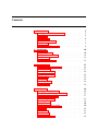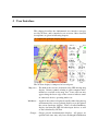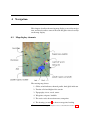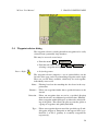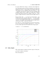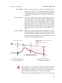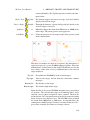
1
XCSoar 6.3
the open-source glide computer
User Manual
Draft state, better you wait printing the
whole manual
March 29, 2012
For XCSoar version 6.3
www.xcsoar.org
XCSoar User Manual
Todo list
1: Write about the manual crossref hinting icons and the
yellow colour. The Quickstart will be readable also
without those links available . . . . . . . . . . . . . .
5
2: explain the principal display modes . . . . . . . . . . . . 17
3: what is that for? . . . . . . . . . . . . . . . . . . . . . . 24
4: This list of dialog explanations (up to ’Text entry’) should
move somewhere else, because it does not explain the
interface. . . . . . . . . . . . . . . . . . . . . . . . . 29
5: still true? . . . . . . . . . . . . . . . . . . . . . . . . . . 66
6: tbd. . . . . . . . . . . . . . . . . . . . . . . . . . . . . . 147
7: tbd. . . . . . . . . . . . . . . . . . . . . . . . . . . . . . 147
8: tbd. . . . . . . . . . . . . . . . . . . . . . . . . . . . . . 147
2
Contents
1
2
3
4
Introduction
1.1 Organization of this manual .
1.2 Notes . . . . . . . . . . . .
1.3 Platforms . . . . . . . . . .
1.4 Technical support . . . . . .
1.5 Training . . . . . . . . . . .
1.6 Using XCSoar safely . . . .
Installation
2.1 Compatibility . . . .
2.2 Software installation
2.3 Data files . . . . . .
2.4 Running XCSoar . .
.
.
.
.
.
.
.
.
User Interface
3.1 Button labels and menus
3.2 InfoBoxes . . . . . . . .
3.3 Status messages . . . . .
3.4 Dialog windows . . . . .
3.5 Sounds . . . . . . . . . .
3.6 Screen . . . . . . . . . .
3.7 Help system . . . . . . .
3.8 Gestures . . . . . . . . .
.
.
.
.
.
.
.
.
.
.
.
.
.
.
.
.
.
.
.
.
.
.
.
.
.
.
.
.
.
.
.
.
.
.
.
.
.
.
.
.
.
.
Navigation
4.1 Map display elements . . . . .
4.2 Glider symbol, map orientation
4.3 Zoom and map scale . . . . .
4.4 Panning the map . . . . . . .
4.5 Waypoints . . . . . . . . . . .
4.6 Active task . . . . . . . . . .
4.7 Terrain and Topography . . . .
4.8 Trail . . . . . . . . . . . . . .
4.9 Markers . . . . . . . . . . . .
4.10 Thermals . . . . . . . . . . .
4.11 Glide range line . . . . . . . .
.
.
.
.
.
.
.
.
.
.
.
.
.
.
.
.
.
.
.
.
.
.
.
.
.
.
.
.
.
.
.
.
.
.
.
.
.
.
.
.
.
.
.
.
.
.
.
.
.
.
.
.
.
.
.
.
.
.
.
.
.
.
.
.
.
.
.
.
.
.
.
.
.
.
.
.
.
.
.
.
.
.
.
.
.
.
.
.
.
.
.
.
.
.
.
.
.
.
.
.
.
.
.
.
.
.
.
.
.
.
.
.
.
.
.
.
.
.
.
.
.
.
.
.
.
.
.
.
.
.
.
.
.
.
.
.
.
.
.
.
.
.
.
.
.
.
.
.
.
.
.
.
.
.
.
.
.
.
.
.
.
.
.
.
.
.
.
.
.
.
.
.
.
.
.
.
.
.
.
.
.
.
.
.
.
.
.
.
.
.
.
.
.
.
.
.
.
.
.
.
.
.
.
.
.
.
.
.
.
.
.
.
.
.
.
.
.
.
.
.
.
.
.
.
.
.
.
.
.
.
.
.
.
.
.
.
.
.
.
.
.
.
.
.
.
.
.
.
.
.
.
.
.
.
.
.
.
.
.
.
.
.
.
.
.
.
.
.
.
.
.
.
.
.
.
.
.
.
.
.
.
.
.
.
.
.
.
.
.
.
.
.
.
.
.
.
5
5
6
6
7
8
9
.
.
.
.
10
10
12
13
13
.
.
.
.
.
.
.
.
17
19
27
28
29
34
34
34
35
.
.
.
.
.
.
.
.
.
.
.
36
36
37
37
38
39
40
40
42
43
43
44
XCSoar User Manual
Contents
4.12 Status dialog . . . . . . . . . . . . . . . . . . . . . 45
4.13 Route . . . . . . . . . . . . . . . . . . . . . . . . 46
5
6
7
Cross Country Tasks
5.1 Goto tasks . . . . . . . . . . . . . .
5.2 Editing tasks . . . . . . . . . . . . .
5.3 Waypoint Info dialog . . . . . . . .
5.4 Waypoint selector dialog . . . . . .
5.5 Task manager . . . . . . . . . . . .
5.6 Advancing and restarting tasks . . .
5.7 Task rules . . . . . . . . . . . . . .
5.8 Alternate starts . . . . . . . . . . .
5.9 Task calculator dialog . . . . . . . .
5.10 Task status dialog . . . . . . . . . .
5.11 Assigned Area Tasks . . . . . . . .
5.12 OnLine Contest . . . . . . . . . . .
5.13 Abort/resume the task and Alternates
5.14 Logger . . . . . . . . . . . . . . . .
5.15 Logger replay dialog . . . . . . . .
5.16 Analysis dialog . . . . . . . . . . .
5.17 Sunlight and time . . . . . . . . . .
Glide Computer
6.1 Flight modes . . . . . . .
6.2 MacCready setting . . . .
6.3 Glide polar . . . . . . . .
6.4 Flight setup dialog . . . .
6.5 Speed command display .
6.6 Speed to fly . . . . . . . .
6.7 Speed to fly with risk . . .
6.8 Safety heights . . . . . . .
6.9 Final glide calculator . . .
6.10 Display of altitude required
6.11 Task speed estimation . . .
6.12 Optimal cruise track . . . .
6.13 Auto MacCready . . . . .
6.14 Analysis dialog . . . . . .
6.15 Flight notifications . . . .
.
.
.
.
.
.
.
.
.
.
.
.
.
.
.
.
.
.
.
.
.
.
.
.
.
.
.
.
.
.
.
.
.
.
.
.
.
.
.
.
.
.
.
.
.
.
.
.
.
.
.
.
.
.
.
.
.
.
.
.
.
.
.
.
.
.
.
.
.
.
.
.
.
.
.
.
.
.
.
.
.
.
.
.
.
.
.
.
.
.
.
.
.
.
.
.
.
.
.
.
.
.
.
.
.
.
.
.
.
.
.
.
.
.
.
.
.
.
.
.
.
.
.
.
.
.
.
.
.
.
.
.
.
.
.
.
.
.
.
.
.
.
.
.
.
.
.
.
.
.
.
.
.
.
.
.
.
.
.
.
.
.
.
.
.
.
.
.
.
.
.
.
.
.
.
.
.
.
.
.
.
.
.
.
.
.
.
.
.
.
.
.
.
.
.
.
.
.
.
.
.
.
.
.
.
.
.
.
.
.
.
.
.
.
.
.
.
.
.
.
.
.
.
.
.
.
.
.
.
.
.
.
.
.
.
.
.
.
.
.
.
.
.
.
.
.
.
.
.
.
.
.
.
.
.
.
.
.
.
.
.
.
.
.
.
.
.
.
.
.
.
.
.
.
.
.
.
.
.
.
.
.
.
.
.
.
.
.
.
.
.
.
.
.
.
.
.
.
.
.
.
.
.
.
.
.
.
.
.
.
.
.
.
.
.
.
48
48
48
49
52
53
56
58
59
60
61
61
66
67
68
69
69
71
.
.
.
.
.
.
.
.
.
.
.
.
.
.
.
72
72
73
74
75
76
76
77
78
80
81
83
85
86
88
89
Atmosphere and Instruments
90
7.1 Variometer . . . . . . . . . . . . . . . . . . . . . . 90
7.2 Air data inputs . . . . . . . . . . . . . . . . . . . . 91
4
XCSoar User Manual
Contents
7.3
7.4
7.5
7.6
7.7
7.8
7.9
7.10
7.11
8
9
Wind display . . . .
Wind estimation . . .
Wind settings dialog
Thermal profile . . .
Thermal locator . . .
Thermal assistant . .
Convection forecast .
Analysis dialog . . .
Weather forecast . .
.
.
.
.
.
.
.
.
.
.
.
.
.
.
.
.
.
.
.
.
.
.
.
.
.
.
.
.
.
.
.
.
.
.
.
.
.
.
.
.
.
.
.
.
.
Airspace, Traffic and Team Flying
8.1 Airspace display . . . . . . . .
8.2 Airspace warnings . . . . . .
8.3 Airspace query and details . .
8.4 Analysis dialogue . . . . . . .
8.5 FLARM traffic . . . . . . . .
8.6 Team flying . . . . . . . . . .
Avionics and Airframe
9.1 Battery life . . . . . . . .
9.2 GPS connection . . . . . .
9.3 Switch inputs . . . . . . .
9.4 Switch dialog . . . . . . .
9.5 Slave mode . . . . . . . .
9.6 System status dialog . . .
9.7 Multiple devices . . . . . .
9.8 Managing external devices
.
.
.
.
.
.
.
.
.
.
.
.
.
.
.
.
.
.
.
.
.
.
.
.
.
.
.
.
.
.
.
.
.
.
.
.
.
.
.
.
.
.
.
.
.
.
.
.
.
.
.
.
.
.
.
.
.
.
.
.
.
.
.
.
.
.
.
.
.
.
.
.
.
.
.
.
.
.
.
.
.
.
.
.
.
.
.
.
.
.
.
.
.
.
.
.
.
.
.
.
.
.
.
.
.
.
.
.
.
.
.
.
.
.
.
.
.
.
.
.
.
.
.
.
.
.
.
.
.
.
.
.
.
.
.
.
.
.
.
.
.
.
.
.
.
.
.
.
.
.
.
.
.
.
.
.
.
.
.
.
.
.
.
.
.
.
.
.
.
.
.
.
.
.
.
.
.
.
.
.
.
.
.
.
.
.
.
.
.
.
.
.
.
.
.
.
.
.
.
.
.
.
.
.
.
.
.
.
.
.
.
.
.
.
.
.
.
.
.
.
.
.
.
.
.
.
.
.
.
.
.
.
.
.
.
.
.
.
.
.
.
.
.
.
.
.
.
.
.
.
.
.
.
.
.
91
92
94
94
95
96
97
97
98
.
.
.
.
.
.
104
104
105
108
109
109
113
.
.
.
.
.
.
.
.
114
114
115
115
116
117
117
117
118
10 Quickstart
119
10.1 Local flight . . . . . . . . . . . . . . . . . . . . . 119
10.2 FAI Task . . . . . . . . . . . . . . . . . . . . . . . 120
10.3 AAT Task, Manual Arm . . . . . . . . . . . . . . . 122
11 InfoBox Reference
11.1 Altitude . . .
11.2 Aircraft state
11.3 Glide ratio . .
11.4 Variometer . .
11.5 Atmosphere .
11.6 MacCready .
11.7 Navigation . .
11.8 Waypoint . .
.
.
.
.
.
.
.
.
.
.
.
.
.
.
.
.
.
.
.
.
.
.
.
.
.
.
.
.
.
.
.
.
.
.
.
.
.
.
.
.
.
.
.
.
.
.
.
.
.
.
.
.
.
.
.
.
.
.
.
.
.
.
.
.
.
.
.
.
.
.
.
.
.
.
.
.
.
.
.
.
.
.
.
.
.
.
.
.
.
.
.
.
.
.
.
.
.
.
.
.
.
.
.
.
.
.
.
.
.
.
.
.
.
.
.
.
.
.
.
.
.
.
.
.
.
.
.
.
.
.
.
.
.
.
.
.
.
.
.
.
.
.
.
.
.
.
.
.
.
.
.
.
.
.
.
.
.
.
.
.
125
125
126
126
127
128
129
130
131
5
XCSoar User Manual
Contents
11.9 Team code . . . . . . . . . . . . . . . . . . . . . . 132
11.10Device status . . . . . . . . . . . . . . . . . . . . 132
11.11Alternates . . . . . . . . . . . . . . . . . . . . . . 132
12 Configuration
12.1 Scope of configuration . . . . . . .
12.2 Modifying settings . . . . . . . . .
12.3 Site Files / Site Files . . . . . . . .
12.4 Map Display / Orientation . . . . .
12.5 Map Display / Elements . . . . . . .
12.6 Map Display / Waypoints . . . . . .
12.7 Map Display / Terrain . . . . . . . .
12.8 Map Display / Airspace . . . . . . .
12.9 Glide Computer / Safety Factors . .
12.10Glide Computer / Glide Computer .
12.11Glide Computer / Wind . . . . . . .
12.12Glide Computer / Route . . . . . . .
12.13Gauges / FLARM, Other . . . . . .
12.14Gauges / Vario . . . . . . . . . . . .
12.15Task Defaults / Task Rules . . . . .
12.16Task Defaults / Turnpoint Types . .
12.17Look / Language, Input . . . . . . .
12.18Look / Screen Layout . . . . . . . .
12.19Look / InfoBox Pages (or just Pages)
12.20InfoBox Sets (or InfoBox Modes) .
12.21Setup / Devices . . . . . . . . . . .
12.22Setup / Polar . . . . . . . . . . . . .
12.23Setup / Logger . . . . . . . . . . . .
12.24Setup / Units . . . . . . . . . . . .
12.25Setup / Time . . . . . . . . . . . . .
12.26Setup / Tracking . . . . . . . . . . .
13 Data Files
13.1 File management
13.2 Map Database . .
13.3 Waypoints . . . .
13.4 Airspace . . . . .
13.5 Airfield details .
13.6 Glide polar . . .
13.7 Profiles . . . . .
13.8 Checklist . . . .
13.9 Tasks . . . . . .
.
.
.
.
.
.
.
.
.
.
.
.
.
.
.
.
.
.
.
.
.
.
.
.
.
.
.
.
.
.
.
.
.
.
.
.
.
.
.
.
.
.
.
.
.
.
.
.
.
.
.
.
.
.
.
.
.
.
.
.
.
.
.
.
.
.
.
.
.
.
.
.
.
.
.
.
.
.
.
.
.
.
.
.
.
.
.
.
.
.
.
.
.
.
.
.
.
.
.
.
.
.
.
.
.
.
.
.
.
.
.
.
.
.
.
.
.
.
.
.
.
.
.
.
.
.
.
.
.
.
.
.
.
.
.
.
.
.
.
.
.
.
.
.
.
.
.
.
.
.
.
.
.
.
.
.
.
.
.
.
.
.
.
.
.
.
.
.
.
.
.
.
.
.
.
.
.
.
.
.
.
.
.
.
.
.
.
.
.
.
.
.
.
.
.
.
.
.
.
.
.
.
.
.
.
.
.
.
.
.
.
.
.
.
.
.
.
.
.
.
.
.
.
.
.
.
.
.
.
.
.
.
.
.
.
.
.
.
.
.
.
.
.
.
.
.
.
.
.
.
.
.
.
.
.
.
.
.
.
.
.
.
.
.
.
.
.
.
.
.
.
.
.
.
.
.
.
.
.
.
.
.
.
.
.
.
.
.
.
.
.
.
.
.
.
.
.
.
.
.
.
.
.
.
.
.
.
.
.
.
.
.
.
.
.
.
.
.
.
.
.
.
.
.
.
.
.
.
.
.
.
.
.
.
.
.
.
.
.
.
.
.
.
.
.
.
.
.
.
.
.
.
.
.
.
.
.
.
.
.
.
134
134
134
135
137
137
138
139
141
142
143
144
144
145
145
146
147
147
148
149
149
150
151
152
153
153
154
.
.
.
.
.
.
.
.
.
155
155
156
156
157
157
158
159
160
160
6
XCSoar User Manual
Contents
13.10Flight logs . . . . . . .
13.11FLARM Identification
13.12Input events . . . . . .
13.13Status . . . . . . . . .
.
.
.
.
14 History and Development
14.1 Product history . . . . .
14.2 Get involved . . . . . . .
14.3 Open source philosophy
14.4 Development process . .
14.5 User base . . . . . . . .
14.6 Credits . . . . . . . . . .
A GNU General Public License
.
.
.
.
.
.
.
.
.
.
.
.
.
.
.
.
.
.
.
.
.
.
.
.
.
.
.
.
.
.
.
.
.
.
.
.
.
.
.
.
.
.
.
.
.
.
.
.
.
.
.
.
.
.
.
.
.
.
.
.
.
.
.
.
.
.
.
.
.
.
.
.
.
.
.
.
.
.
.
.
.
.
.
.
.
.
.
.
.
.
.
.
.
.
.
.
.
.
.
.
.
.
.
.
.
.
.
.
.
.
.
.
.
.
.
.
.
.
.
.
.
.
.
.
.
.
.
.
.
.
.
.
.
.
161
161
161
162
.
.
.
.
.
.
163
163
164
165
166
166
167
170
7
Preface
Warnings and precautions
IT IS THE USER’S RESPONSIBILITY TO USE THIS SOFTWARE PRUDENTLY. THIS SOFTWARE IS INTENDED TO BE
USED ONLY AS A NAVIGATION AID AND MUST NOT BE
USED FOR ANY PURPOSE REQUIRING PRECISE MEASUREMENT OF DIRECTION, DISTANCE, LOCATION, OR TOPOGRAPHY. THIS SOFTWARE SHOULD NOT BE USED AS AN
AID TO DETERMINE GROUND PROXIMITY FOR AIRCRAFT
NAVIGATION. THIS SOFTWARE SHOULD NOT BE USED
AS A TRAFFIC COLLISION AVOIDANCE SYSTEM.
Legal notices
Software license agreement
This software is released according to the GNU General Public License Version 2. See Appendix A for the full text of the agreement
and warranty notice.
Limited liability
In no event shall XCSoar, or its principals, shareholders, officers,
employees, affiliates, contractors, subsidiaries, or parent organizations, be liable for any incidental, consequential, or punitive damages whatsoever relating to the use of the Product.
Disclaimer
This product, and all accompanying files, data and materials, are
distributed ”as is” and with no warranties of any kind, whether express or implied. This product is used entirely at the risk of the
user. Although great care has been taken to eliminate defects during its development it is not claimed to be fault-free. No claims
are made regarding its correctness, reliability or fitness for any
particular purpose. The XCSoar project developers and contributors shall not be liable for errors contained herein or for incidental
or consequential damages, loss of data or personal injury in connection with furnishing, performance, or use of this material.
1
Introduction
This document is a pilot’s manual for XCSoar, an open-source
glide computer originally developed for Pocket PC devices. The
audience is assumed to have a sound knowledge of the fundamental theory of flight for gliders, and at least a basic working knowledge of cross-country soaring.
Updates to the XCSoar software may result in some of this manual
being out of date. You should read the release notes distributed
with the software to keep track of changes. Updates to the manual
and software are available from
www.xcsoar.org
1.1
Organization of this manual
1: Write about the manual crossref hinting icons and the
yellow colour. The Quickstart will be readable also without
those links available
This manual is broadly organized into the major functions of the
software from a pilot’s perspective. The remainder of this chapter
deals with how to download, install and run the software on various platforms. Chapter 3 introduces the user interface concepts
and gives an overview of the display.
Chapter 4 describes the moving map part of the display in greater
detail and describes how the software can assist in general navigation. Chapter 5 describes how cross-country tasks are specified
and flown, and presents some of the analysis tools available to pilots to help improve their performance. Chapter 6 goes into further
detail on the glide computer functions as it is important for pilots
to be aware of how the computer performs its calculations.
Chapter 7 describes how the computer can interface to variometers
and other air data sensors, and how it uses these measurements to
provide various models of the atmosphere, in particular on winds
and thermal convection. Chapter 8 describes how XCSoar can assist in managing flight in special use airspace and the FLARM
collision awareness system. Chapter 9 deals with systems integration and systems diagnostics, the integration of XCSoar with
communications devices and with airframe switches.
XCSoar User Manual
1. INTRODUCTION
The remainder of the manual contains mainly reference material.
Chapter 11 lists the types of information that can be displayed in
the grid of InfoBoxes next to the map display. The configuration
of the software is described in detail in Chapter 12. The formats of
the various data files that program uses, as well as where to obtain
them from and how to edit them, is described in Chapter 13.
Finally, a short history and discussion of XCSoar’s development
process is presented in Chapter 14.
1.2
Notes
Terminology
A variety of terms may be used to describe embedded devices like
the Pocket PC platform, including ‘organiser’, Portable Digital
Assistant (PDA) and Personal Navigation Assistant (PNA). XCSoar is also available on Triadis Engineering’s Altair glide computer, which is formally an Electronic Flight Instrumentation System, and several other platforms. Throughout this document, these
terms are used interchangeably to refer to whatever hardware XCSoar is running on.
Screenshots
Throughout this manual are several screenshots of XCSoar. These
are taken from the program running on a variety of hardware platforms and possibly even different versions. Each platform and
version may have different screen resolutions, layouts and fonts,
and so there may be slight differences in the appearance of the display. Most of the screenshots in this manual are taken of XCSoar
running in landscape orientation.
1.3
Platforms
Windows PC : It is possible to run XCSoar on an ordinary computer with
the Windows operating system. This setup can be used for
training yourself in using XCSoar. A simulation mode is
included in XCSoar as well as a IGC replay function, that
can be used when not connected to a valid GPS source.
Windows Mobile PDA/PNA : Devices powered by Microsoft Pocket PC 2000 up to Windows Mobile 6 are supported by XCSoar. Windows Mobile
7 will not be supported as Microsoft decided to skip support
for native applications from this version on.
10
XCSoar User Manual
1. INTRODUCTION
Unix/Linux PC : XCSoar can be run on Unix using the Wine emulator. A
native Unix port has been released with the 6.0 version of
XCSoar, but is still considered experimental.
Android Devices : XCSoar runs on Android 1.6 or newer.
Altair : The Altair glide computer by Triadis Engineering is a glide
computer factory installed with XCSoar. The Altair PRO
version also contains an internal GPS.
1.4
Technical support
Troubleshooting
A small team of dedicated developers produces XCSoar. Although
we are happy to help with the use of our software, we cannot teach
you about basics of modern information technology. If you have a
question about XCSoar in particular please email us at:
[email protected].
Any frequent questions will be added to this document and to the
Frequently Asked Questions (FAQ) section of the XCSoar website.
You may also find it useful to subscribe to the XCSoar users mailing list so you will be kept up to date with latest developments.
You can find more information about the XCSoar mailing lists on
our website:
www.xcsoar.org
A log file of the startup progress of XCSoar is generated in the file
xcsoar-startup.log. This can be sent to the XCSoar developers to help determine the cause of any startup related problems.
For Altair users, the startup file is transferred to the ‘FromAltair’
directory by AltairSync if a USB drive is plugged in when Altair
is first switched on.
Updates
You should periodically visit the XCSoar website to check for program updates. The installation procedure described above can
typically be repeated in order to upgrade the software. All user
configuration settings and data files will be preserved during the
re-installation/upgrade.
It is also recommended to periodically check for updates to data
files, particularly Special Use Airspace, which may be subject to
change by the national civil aviation authority.
11
XCSoar User Manual
1. INTRODUCTION
Like any complex software program, XCSoar may be subject to
software bugs, so if you find any, please report them to the XCSoar
developers by using our bug tracker “trac” at
http://www.xcsoar.org/trac/
or by sending an email to
[email protected]
Updating XCSoar on Altair
Updating XCSoar on Altair involves downloading the latest program file XCSoarAltair-YYY-CRCXX.exe, copying it to a
USB memory stick, then using the AltairSync utility on the Altair
device to complete the installation. Refer to the Altair Owner’s
Manual for details.
Other data and program files can be transferred to Altair in a similar way.
1.5
Training
For the safety of yourself and others, pilots using XCSoar are advised to train themselves in using XCSoar on the ground and become familiar with its interface and features prior to flight.
Using XCSoar on the PC
The PC versions of XCSoar may be used to become familiar with
XCSoar’s interface and functionality in the comfort of one’s home.
All files and configuration used by this version are identical to the
embedded versions, so it can be helpful to try out customisations
on the PC version before using them in flight.
The PC versions can also be connected to external devices and
operate just as the embedded versions do. Suggested uses include:
• Connect the PC to a FLARM device to use XCSoar as a
ground station display of FLARM-equipped traffic.
• Connect the PC to an intelligent variometer such as Vega to
test configuration settings of the variometer.
Using XCSoar with a flight simulator
A good way to learn how to use XCSoar is to connect the Pocket
PC device to a PC running a flight simulator that can output NMEA
sentences to the serial port. Suitable simulators include Condor
and X-Plane.
12
XCSoar User Manual
1. INTRODUCTION
The benefit of this form of training is that XCSoar can be used in
FLY mode, so it behaves exactly as if you were really flying, and
you can get a good feel for how the program works while you are
flying the simulator.
1.6
Using XCSoar safely
The use of an interactive system like XCSoar in flight carries with
it certain risks due to the potential distraction of the pilot from
maintaining situational awareness and eyes outside the cockpit.
The philosophy guiding the design and development of the software is to try to reduce this distraction by minimising the need for
user interactions as much as possible, and by presenting information in a clear fashion able to be interpreted in a glance.
Pilots using XCSoar must take responsibility for using the system
safely. Good practice in the use of XCSoar includes:
• Becoming familiar with the system thoroughly through training on the ground.
• Performing clearing turns before interacting with XCSoar in
flight in order to ensure there is no collision risk with other
traffic.
• Setting up the system to take advantage of automatic functions and input events so that user interactions can be minimised. If you find yourself mechanically performing certain interactions frequently, ask yourself (or other XCSoar
users) if the software can be made to do these interactions
for you.
13
2
Installation
To run XCSoar, you need to obtain the following:
• a device to run XCSoar on
• XCSoar
• a GPS receiver
• a waypoint file
• an airspace file (optional)
• a map file (optional)
2.1
Compatibility
Devices for running XCSoar
XCSoar runs on the following platforms:
• mobile phones and tablets with Android 1.6 or newer
Example: Dell Streak, Samsung Galaxy S II, HTC Desire
HD, Motorola Xoom
• PDAs with Pocket PC 2000, 2002, 2003
Example: iPaq 3800, iPaq 3900
• PDAs with Windows Mobile
Example: iPaq hx4700, Dell Axim x51v
• PNAs with Windows CE 3.0 or newer
Example: HP314, Mio400
• Triadis Altair
• LX MiniMap
• Windows 2000 or newer
• Linux
XCSoar User Manual
2. INSTALLATION
GPS, Logger, Vario
XCSoar is compatible with any GPS emitting NMEA data. Most
modern Android devices have a built-in GPS, but sometimes it is
favorable to connect to an external device:
• an airspeed indicator allows quick and exact wind estimates
without circling
• a vario improves the thermal assistant
• a task can be declared to an IGC logger, and after landing,
the flight log can be downloaded
• some varios allow synchronising the MacCready setting with
XCSoar
Supported external devices and features
Feature
NMEA
Device
Airspeed
√
Borgelt B50
√
CAI 302
CAI GPS Nav
√
Condor
√
Digifly Leonardo
EW Logger
EW microRecorder
Flymaster F1
√
Flytec 5030
ILEC SN10
IMI ERIXX
LX20, Colibri
√
LX 5000, 7000
PosiGraph
Triadis Altair
√
Triadis Vega
Volkslogger
√
Westerboer VW1150
√
Zander / SDI
Vario
Declaration
Download
√
√
√
√
√
√
√
√
√
√
√
√
√
√
√
√
√
√
√
√
√
While most Windows CE based devices have a serial port, such
legacy hardware is not present in modern Android devices. Those
can either use Bluetooth or the Android IOIO board. To use Bluetooth, you need to connect the external device to a Bluetooth-toSerial adapter, such as the K6-Bt or the Glidertools VFBT-1.
15
XCSoar User Manual
2.2
2. INSTALLATION
Software installation
The software is available as a free download from the XCSoar
website www.xcsoar.org. This section describes which file
should be downloaded, and how to install it.
On Android
Obtain XCSoar from Google’s Android market, or install the apk
file manually. Copy the data files on the SD card in the directory
XCSoarData.
On a PDA (Windows Mobile, PocketPC)
Choose one of the targets:
PPC2000 : Pocket PC 2000/2002, Windows CE 3.0
PPC2003 : Pocket PC 2003, Windows CE 4.0
WM5 : Windows Mobile 5 or newer
WM5X : Windows Mobile 5 or newer with XScale CPU or better (e.g.
hx4700)
Download the program file XCSoar.exe to a SD card. You can
launch it with the File Explorer. Another method to install XCSoar
on a PDA is the CAB file. Download it to the SD card. Use the
File Explorer to install it. After the installation, the XCSoar ‘FLY’
and ‘SIM’ launcher icons will be visible on the Today screen.
On a PNA (Windows CE)
Download the program file XCSoar.exe (target “WM5”) to a
SD card. You can launch it with the File Explorer.
On a Windows PC
Download the program file XCSoar.exe (target “PC”) to your
hard disk.
On Unix/Linux
The file downloaded is xcsoar_XXX.deb, where XXX includes
the version number and platform, e.g. xcsoar_6.0.4_i386.deb.
The is a Debian package and can be installed using
sudo dpkg -i xcsoar_XXX.deb.
16
XCSoar User Manual
2. INSTALLATION
Use dpkg-query -L xcsoar to see where the executable and
other files are installed, Additional data files must be placed in the
directory ˜/.xcsoar/XCSoarData/. If ˜/.xcsoar does
not exist, it will be created the first time that xcsoar is run.
2.3
Data files
To be able to use XCSoar’s advanced features, additional data files,
such as terrain, topography, special use airspace, waypoints etc.
are needed. The files that can be used with XCSoar are described
in Chapter 13.
All data files should be copied into the directory XCSoarData.
This directory must be in a specific place so that XCSoar knows
where to look for data files:
Windows PC : XCSoarData is in your personal folder (“My Documents”)
Windows Mobile PDA/PNA : XCSoarData is on the SD card. If there is no SD card,
then XCSoar looks for it in My Documents.
Unix/Linux : The directory is called .xcsoar in the user’s home directory.
Android Devices : XCSoarData is on the SD card.
Altair : If XCSoarData exists on an USB drive, that one is used,
otherwise the internal storage is used.
XCSoar will generate a number of additional files at run time.
These will be placed in the XCSoarData directory (Windows PC
and Windows Mobile devices), or the .xcsoar directory (Unix/Linux
PC). At first run, XCSoar will create the files Default.tsk
(Default Task), xcsoar-registry.prf (configuration settings),
xcsoar-startup.log (log of the startup progress), plus three
directories: cache, config and logs. Additional files may
be created/modified while XCSoar is running, such as task files
(*.tsk) and flight logs.
2.4
Running XCSoar
Two modes are available inside the XCSoar application:
FLY : This mode is used when actually flying. The simulator is
disabled and serial communications are active.
SIM : This starts XCSoar in simulator mode, no serial communications are attempted.
17
XCSoar User Manual
2. INSTALLATION
Altair version
XCSoar starts up automatically when Altair is powered on. The
PWR/ESC button (top left) has multiple functions:
Powering on : Press and hold the PWR/ESC button for one second. The
LED in the button will light up, and XCSoar will start after
Altair has booted.
Powering off : Press and hold the PWR/ESC button for 3 seconds. Altair
will switch off.
Escape : Pressing the PWR/ESC button quickly acts as an Escape
key, typically used to close dialog pages or as a cancel function.
The Altair version of XCSoar does not include a simulator mode.
XCSoar PC version
The program can be run by opening the explorer window, finding the directory that has the XCSoar.exe executable, and double
clicking on that program file.
The program command line options allows the screen orientation
of the display to be defined:
-portrait : The screen is 480 pixels wide, 640 pixels high.
-square : The screen is 480 pixels wide, 480 pixels high.
-landscape : The screen is 640 pixels wide, 480 pixels high. This is the
usual setting. If you don’t specify this parameter the landscape version will be loaded automatically.
-small : Draws the screen at half size. This is useful for using XCSoar in conjunction with flight simulators e.g. Condor.
To change the screen orientation, it is convenient to create a shortcut to the program, then right click on the shortcut icon and click
on “Shortcut”. In the field “Target” add one of the desired options
listed above.
XCSoar Unix/Linux PC version
Run xcsoar from a command line, or create a shortcut on the
desktop. The location of the executable file may be found using
which xcsoar. Only landscape mode is supported for now.
18
XCSoar User Manual
2. INSTALLATION
Loading data files
The first time that XCSoar is run, it does not automatically load the
data files that you placed in the XCSoarData directory. To tell
XCSoar which files to load, double click/tap the map (the large,
blank white part with the glider symbol in the center), choose the
menu Config (click/tap it twice), then select System Setup
. The System Setup screen should be displayed: The first page allows you to choose the map, waypoint and airspace files, by clicking/tapping on the text boxes. Many other features of XCSoar may
be configured with System Setup . These are described in detail in Chapter 12. Once completed, XCSoar reloads those files;
from now on, the data files will be loaded automatically at run
time.
Start-up and user profiles
When XCSoar starts up, it will check for existing profiles. If multiple profiles are detected it will displays a small window asking
you which profile to load. To proceed, choose the desired profile
and press Enter. If no profile is chosen the settings from the last
session are loaded again. Profiles can be useful for example in the
following cases:
• Different pilots
• Competition versus casual flying
• Flying in different locations
SIM mode
The simulator contains a simple interface allowing the user to
fly the glider about. On the map screen, clicking/touching the
glider symbol (with touchscreen or mouse) and dragging causes
the glider to move in the direction of the drag, the speed being
proportional to the length of the drag.
In the PC version and for embedded devices with buttons, the aircraft speed, height and direction may be changed using the InfoBoxes. These features are not available for touchscreen devices.
The aircraft altitude can be adjusted by selecting the GPS altitude
InfoBox (marked H GPS ), and pressing the up or down key.
The airspeed can be adjusted by selecting the ground speed InfoBox (marked
V Gnd ), and pressing the up or down key.
The glider’s track can be adjusted by selecting the track InfoBox
(marked
Track ), and pressing the up or down key. With
19
XCSoar User Manual
2. INSTALLATION
either of the InfoBoxes H GPS or V Gnd ) selected, the
glider’s direction may be changed using the left/right keys.
Other controls, buttons and menus work the same as in FLY mode.
Splash screen
When XCSoar starts up, shuts down, or loads large files, such as
airspace, waypoints, terrain, etc., a progress screen is presented
while the data is being loaded. This screen has a progress bar
which indicates the data loading activity, and a short line of text
describing the action that is being performed.
This screen also displays the software version information.
Exiting the program
For PDA and PC versions, XCSoar is shut down from the menu.
The menu can be opened by double-clicking on the map or the
InfoBoxes.
QUIT
For PC versions, XCSoar can also be shut down by clicking the
close icon on the XCSoar window.
For Altair, XCSoar is shut down by holding the PWR button for
two seconds or more.
20
3
User Interface
This chapter describes the fundamental user interface concepts
used by XCSoar, and is intended as an overview. More detailed
descriptions are given in following chapters.
2: explain the principal display modes
The XCSoar display is composed of several parts:
Map area : The bulk of the screen is dedicated to the GPS moving map
display. Various symbols relating to glide computer information are overlaid on the map area. Icons and text may
appear along the lower edge of the screen to indicate status
of connected devices, operating modes etc.
InfoBoxes : A grid of data values is displayed usually either along the top
and bottom of the screen (portrait display) or to the right of
the screen (landscape display). These so-called InfoBoxes
display data from the GPS and other input devices as well
as data calculated by XCSoar.
Gauges : Gauges provide instrumentation displays. All gauges are
optional and some may only have meaningful information
XCSoar User Manual
3. USER INTERFACE
displayed when XCSoar is connected to a supported instrument.
Button labels and menus : Hardware buttons on the device running XCSoar can be used
to bring up and navigate smaller on-screen menus that are
typically laid out such that menu items can be selected by
pressing the button adjacent to the item. If the device has
a touch screen, the menu items can be selected by touching them. These buttons are drawn in black text on a green
background.
Status messages : Text is displayed over the map area in status message boxes.
This text is used to present detailed information to the pilot
when certain events occur.
Dialog windows : Larger dialog windows, usually containing graphics and buttons, are used to present detailed data to the pilot regarding
waypoint details, statistics and analysis etc.
Main menu : The main menu is accessible by double tapping the map area
Down - Up
or infoboxes as well as through gesture. If the menu buttons
are not pressed after a specified time, they disappear again
so as to not obscure the map area.
There are several ways to interact with XCSoar:
• Touching certain map elements
• Touching InfoBoxes and onscreen menu buttons
• ‘Gesturing’, by e.g. drawing a dash from the left to the right
on the screen (see Section 3.8 below).
• ‘Dragging’ the screen (touching the screen and moving before releasing).
• Pressing application buttons on the device.
• Pressing the cursor keys on the device.
• Pressing keys or switches on an instrument connected to
XCSoar.
Depending on the particular hardware used with XCSoar, not all
of these methods of interaction are possible and there may be different numbers or assignments of buttons.
For the PC version of XCSoar, clicking the mouse over an item is
equivalent to touching it.
Since the Altair does not have a touch screen, all user interaction
is performed via physical buttons, switches or other external interface devices if connected.
22
XCSoar User Manual
3.1
3. USER INTERFACE
Button labels and menus
The button menu is a set of buttons drawn on the screen and activated by touch or hardware button presses. Using buttons and the
button menu is the primary way the user interacts with XCSoar.
Interface basics
The menu is organised into four different groups of functions, usually in the form of a hierarchy. The specific menu layout depends
on the hardware button configurations and platform, and may also
be customised by the user.
XCSoar can also accept input from external keyboards, gamepads, joysticks, stick grip switches etc. A wide variety of functions
can be assigned to these inputs.
For Altair, there are four major menus, activated by pressing one
of the vertical strip of hardware buttons on the left of the display.
When a menu is activated, a strip of onscreen buttons appear along
the bottom of the display. Pressing the particular menu button
again will cycle through several pages of items. Pressing the corresponding horizontal button will activate that item. At the last
page, pressing the menu button again will turn that menu off and
the horizontal strip of onscreen buttons disappear.
On the PC version, these mode buttons are activated by the 1, 2, 3
and 4 keys. The 6, 7, 8, 9 and 0 keys correspond to the horizontal
strip of buttons.
23
XCSoar User Manual
3. USER INTERFACE
On the PDA version, the mode buttons are activated by the keys to
the side of the joystick/rocker button.
If the user doesn’t interact with the computer for some time, the
menu will close automatically. This menu timeout is configurable.
The escape key on PC, or the PWR/ESC button on Altair, can also
be used to close the current menu.
Menu buttons appear greyed out if the corresponding function is
not available. For example, the “Waypoint list” function will appear grey if there are no waypoints loaded.
Several menu button labels have dynamic text based on context,
in order to make it clearer as to what happens when the button
is pressed. The convention is used that a button’s label describes
what will happen when the button is pressed. For example, if the
button says MC Auto , then pressing the button will turn on auto
MacCready, and the button label will then change to MC Manual
. In the menu list described below, generic labels are used.
Menu overview
This section describes the default layout of the menu system on all
platforms. The functions performed by each button are explained
more fully in following chapters.
The primary menu buttons are activated by each of the vertical
strip of buttons on Altair, from top to bottom:
Nav : Actions for navigation control, primarily cross-country gliding tasks.
Display : Actions to control the display.
Config : Configuration of XCSoar, connected devices, and in-flight
settings.
Info : Activates various informational dialog windows.
For the PC version, the keys 1, 2, 3 and 4 activate the corresponding menu.
Navigation menu (Nav)
Task
Calc
Displays the task calculator dialog.
Arm
Start
Arms the automatic task waypoint trigger.
24
XCSoar User Manual
3. USER INTERFACE
Previous
turnpoint
Selects the previous/start waypoint in the task.
Next
turnpoint
Selects the next/finish waypoint in the task.
Waypoint
List
Displays the waypoint selector dialog.
Task
Edit
GoTo
Task
Abort
Alternates
Target
Displays the task editor.
Displays the waypoint selector dialog and activates the GoTo
mode for the selected waypoint.
Aborts/resumes the current task.
Shows a list to landable alternates in the near, sorted by by the
configured aspect and distance.
Displays the target dialog, which is important for modifying
AAT tasks.
Display menu
Zoom
In
Zooms in the map display.
Zoom
Out
Zooms out the map display.
Zoom
Auto
Toggles automatic/manual zooming.
Mark
Drop
Drops a marker at the current glider location.
Pan
On
Activates pan map mode.
Labels
On
Displays map labels, MID labels, or none.
25
XCSoar User Manual
Trail
Full
Terrain
On
3. USER INTERFACE
Selects a display option out of Full, Long, Short, Off.
Toggles display of terrain.
Topology
On
Toggles display of topology.
Info
Auto
Steps through InfoBox grids.
Configuration menu (Config)
MC
+
Increases MacCready value.
MC
−
Decreases MacCready value.
MC
Auto
Toggles automatic/manual MacCready.
Flight
Setup
Displays the flight settings (bugs/ballast/QNH) dialog.
Setup
Wind
Displays the wind settings dialog.
Vario
Control of Vega intelligent variometer, this comprises a submenu.
Setup
System
Displays the XCSoar configuration dialog.
Settings
Airspace
Displays the airspace filter dialog.
Logger
Start
Replay
Turns on/off XCSoar’s software IGC flight recorder.
Displays the IGC/NMEA logger replay dialog.
26
XCSoar User Manual
Raw
Logger
Devices
Setup Plane
3. USER INTERFACE
Activates the raw NMEA logger (usually only used for debugging).
Displays the Device connection dialog.
Displays the selection dialog for plane profiles.
Information menu (Info)
FLARM
Radar
Opens the full screen FLARM radar dialog.
METAR
TAF
Displays the METAR/TAF dialog.
Nearest
Airspace
Displays details of the airspace nearest to the aircraft.
Waypoint
Details
Check
List
Analysis
Status
Weather
Team
Code
FLARM
Details
Thermal
Assistant
Displays the waypoint details dialog of the active task waypoint.
Displays the check list dialog.
Displays the analysis/statistics dialog.
Displays the status dialog.
Displays the weather forecast dialog.
Opens the team code dialog.
Opens the FLARM details dialog.
Opens the full screen thermal assistant dialog.
27
XCSoar User Manual
Credits
3. USER INTERFACE
Displays version information and developer team details.
Nearest
Waypoint
Displays details of the waypoint nearest to the aircraft.
Message
Repeat
Repeats the last status message.
Variometer sub-menu (Vario) of the Configuration menu
The functions in this sub-menu require the Vega intelligent variometer. The menu can only be accessed if “Vega” is selected as
the connected device.
Airframe
Switches
Setup
Audio
Manual
Demo
Setup
Stall
Displays airframe switch values.
Adjusts volume of sounds produced by XCSoar as well as certain speech announcements by the Vega intelligent variometer.
Activates Vega variometer manual tone demo.
Opens Vega stall monitor setup dialog.
Accel
3: what is that for?
ASI
Zero
Zeros the airspeed indicator.
Accel
Zero
Levels/zeros the accelerometers.
Store
Stores Vega settings to EEPROM.
Cruise
Demo
Activates Vega variometer cruise tone demo.
Climb
Demo
Activates Vega variometer climb tone demo.
28
XCSoar User Manual
3. USER INTERFACE
Pan mode sub-menu of the Display menu
Pan
Off
Turns pan mode off.
Zoom
in
Zooms in the map display.
Zoom
out
Zooms out the map display.
Nearest
Waypoint
Displays the waypoint details dialog of the waypoint nearest to
the aircraft, or if in pan mode, nearest to the cross-hairs at the
center of the screen.
Default buttons
When no menu is active, (so-called default mode), the horizontal
row of buttons in Altair perform the following functions (from left
to right):
PC:
Altair:
6
F5
7
F6
8
F7
9
F8
0
F9
Flight
Setup
Task
Calc
Task
Edit
Arm
Advance
Drop
Mark
Pressing ESC on Altair displays labels for these default menu buttons.
For all other versions in the default mode, the cursor keys perform
the following functions:
Up key : Zoom in
Down key : Zoom out
Left key : Drop marker
Right key : Toggle through normal/aux. InfoBoxes and Fullscreen
Enter : Clear status message or suppress FLARM gauge if open and
no warning active
For the Altair version in the default mode, the rotary knob performs the following functions:
Outer knob counterclockwise : Zoom in
Outer knob clockwise : Zoom out
Inner knob counterclockwise : (No function assigned)
Outer knob clockwise : (No function assigned)
Knob button press : Clear status message or acknowledge airspace warning
29
XCSoar User Manual
3. USER INTERFACE
In dialog forms, the rotary knob in Altair performs the role of the
cursor and enter keys:
Outer knob counterclockwise : Up cursor
Outer knob clockwise : Down cursor
Inner knob counterclockwise : Left cursor
Inner knob clockwise : Right cursor
Knob button press : Enter key
For Altair, the buttons along the edge of the display can be used
as alternate ways of navigating in dialogs. The F4 key (directly
above the rotary knob) can be used as an alternate ENTER key
(instead of pressing the rotary knob) in dialogs. The F6 and F7
keys (directly to the right of the rotary knob) can be used to select
the next or previous page in multipage dialogs.
Dynamic menu labels
Certain menu items have dynamic labels to make it clearer what
happens when the menu item is selected. Furthermore, items that
are not available are greyed out to indicate that selecting the menu
item will not do anything.
The convention used for dynamic menu labels is for the labels to
display the action that will be performed once the menu item is
selected. For example “Lights On” will turn the lights on, and the
menu will be updated to display “Lights Off”, which would then
if pressed turn the lights off. This convention is used throughout
XCSoar.
A selection of key dynamic menu items is presented below:
Next turnpoint : Greyed out if the task is cleared, or if the active turnpoint is
the finish. If the currently active turnpoint is the turnpoint
prior to the finish, this displays “Waypoint finish”.
Previous turnpoint : Greyed out if the task is cleared, or if the active turnpoint
is the start and there are no multiple start points. If there
are multiple start points and the active turnpoint is the start,
then this displays “Cycle start” to allow selection between
the various start points. If the active turnpoint is the first
turnpoint after the start, this displays “Waypoint Start”.
Labels : This now displays “Labels On”, “Labels MID” or “Labels
Off”.
Task calculator : Greyed out if the task is cleared or in task abort.
Arm Advance : Greyed out if Auto or Manual advance mode is active. Displays “Arm start” when the active turnpoint is the start and
30
XCSoar User Manual
3. USER INTERFACE
the trigger is not armed. Displays “Arm Cancel” if the trigger is armed. Displays “Arm turn” if the active turnpoint is
past the start.
Task Edit : Greyed out if there is no waypoint database.
3.2
InfoBoxes
The information displayed in the InfoBox fields can be selected
from a wide variety of options (listed in Chapter 11). These fields
can also be used to set user configurable variables, for example the
MacCready setting.
The specific number and layout of the InfoBox grid depends on
the screen orientation and the device’s display size. For a 320x240
display Pocket PC in portrait mode, there are four InfoBoxes above
and four InfoBoxes below the map display. For landscape mode,
there are 9 InfoBoxes to the right of the map display.
Screen display modes
XC Soar allows the pilot to define various sets of InfoBoxes that
are appropriate to various stages of flight (e.g. when circling in
a thermal, flying between thermals, on final glide, etc.). XC Soar
can be configured to automatically switch from one InfoBox display to another based on the mode of flight, or you can manually
scroll through the various InfoBox displays, including a display
with a full-screen map and no InfoBoxes at all.
Right
To toggle through the various InfoBox displays, using a touchscreen: or
Left
31
XCSoar User Manual
3. USER INTERFACE
Modifying InfoBox values
(This section applies only when a touchscreen or mouse is present.)
Some InfoBox values can be changed by the user by selecting (i.e.
long-pressing) the InfoBox with the touchscreen or mouse. This
brings up a set of InfoBoxes:
Edit : Allows the pilot to adjust the InfoBox setting (e.g. raise or
lower the McCready setting)
Setup : Allows you to change the behavior of the setting related to
the InfoBox (for example, changing from Auto to Manual
McCready setting mode) or choose to setup of the InfoBox
itself (that is, choosing Setup InfoBox will display a list
dialog of all available InfoBoxes from which to choose.
Examples of InfoBoxes that can be adjusted include the MacCready
setting, and the wind speed.
Changing InfoBoxes
InfoBoxes can either be changed by calling the configuration dialog from the menu Config . Config . Setup System Screen
21, ”InfoBox Modes” or by performing a long press on the InfoBox that should be changed. In the second case a list dialog
opens, giving you all available InfoBoxes to choose from.
3.3
Status messages
Status messages appear over the map area to present text for a
short period of time. The message disappears after the time period has elapsed, and different types of message have different
periods. Additionally, status messages can be made to disappear
by acknowledging the message. Acknowledgement is achieved
by either pressing the enter key (rotary knob on Altair), touching
the status message (on touchscreen devices) or clicking the screen
(mouse enabled devices).
Additional user buttons may be assigned to a status message repeat
function, which brings up the last message again.
Typical status messages include:
• Airspace queries
• Airspace warnings
• User interface events (e.g. changing display modes)
32
XCSoar User Manual
3. USER INTERFACE
• Glide computer events (e.g. takeoff, turning waypoints)
Note that status messages do not appear while a dialog is on screen,
the messages are buffered and displayed as soon as the dialog is
exited.
3.4
Dialog windows
XCSoar contains several dialog windows that can be activated to
bring up additional information and are also used for more complex interactions with the user, such as editing tasks and configuring settings.
Some dialogs simply display information, and require no user input. Other dialogs contain data fields that can be modified or buttons that can be pressed.
A cursor appears over the active button or data field. Pressing
the up/down arrow keys (or rotating the outer knob on Altair), the
cursor will cycle through the next or previous items. For list items
and scrollable text, the up/down arrow key moves the cursor up or
down the list or text, and the left/right arrow keys move the cursor
up or down by one page in long lists.
For PDAs and PC versions, list items can be selected by touching
the item (or left-clicking with the mouse). Once a list item is selected, another touch (left click) is equivalent to pressing the enter
key.
Pressing the right/left arrow keys (or rotating the inner knob on Altair), the data field value under the cursor can be modified. Pressing the enter key (or pressing the rotary knob on Altair) activates
the button or makes a selection from a list.
Dialogs are typically started from the button menu.
Many of the dialog windows have multiple pages of information
and are controlled in a consistent fashion. Press the < or >
buttons to select the next or previous page of the dialog and the
Close button to make the dialog disappear.
The escape key on a PC or the PWR/ESC button on Altair, can
also be used to close dialogs.
The user must close the dialog to return to the normal map mode.
When a dialog has been opened, the menu buttons are disabled
until the dialog is closed.
In some dialogs, items that are not relevant or valid (such as AAT
details when flying a non-AAT task) are not displayed.
33
XCSoar User Manual
3. USER INTERFACE
4: This list of dialog explanations (up to ’Text entry’) should
move somewhere else, because it does not explain the interface.
A summary of the major dialogs is presented below.
Flight setup : Used to modify the polar of the glider both before and during
flight, as well as to set the QNH pressure
Wind : Used to modify or adjust the estimated wind magnitude and
direction
Waypoint details : Describes a waypoint in detail and has navigation functions
such as “GoTo” and “Insert in Task”
Waypoint selector : Used to select a waypoint from the waypoint database
Task editor : Used to edit and view cross country tasks
Task calculator : Allows the pilot to see the effect of various changes to the
task on final performance
Analysis : Shows several pages of analysis and statistics about the flight
Status : The status dialogs give summaries of the situation of the
aircraft, system, task, start and times
Checklist : A multi-page custom checklist
Configuration : Allows XCSoar and certain connected devices to be configured
Airspace colours and patterns : Configuration of colours and patterns of airspace used on
the map display
Airspace filter : Controls enabling and disabling the display and warnings of
each airspace class
Team code : Allows transfer of coordinates between team mates via a
code
Devices : Allows setup of various external devices (e.g. glide computers, FLARM, etc.).
Setup Plane : Allows easy reconfiguration of the plane-dependant settings
(e.g. polar, competition ID, etc.) by choosing from a list of
previously-created plane profiles.
These dialogs are described in later chapters. with the exception
of the checklist, status and text entry dialogs, which are described
below.
34
XCSoar User Manual
3. USER INTERFACE
Checklist dialog
The checklist dialog can display several pages of user-defined free
text. Typically this is used for checklists. It can be accessed via
the menu under
Info . Check list
These checklists may include: daily inspection, preflight, outlanding, pre-landing, radio procedures, and aircraft rigging and derigging instructions. Since the checklists may be long, the up/down
keys (or rotary knob on Altair) may be used to scroll through the
text. Clicking the < and > buttons selects the previous/next
checklist.
Status dialog
The status dialog is a multi-tabular dialog giving overview information on the flight, system, task, rules and times. Note that the
values in the Status dialog are static once the particular dialog page
is displayed. That is, position, times, etc. do not update while the
page is displayed. To see the updated values, it is necessary to select a different dialog, then return to the previous dialog to see the
new values.
Left - Down - Right - This dialog is accessed via the menu (or by gesture ”S”)
Down - Left
Info . Status
Flight : Shows the location of the aircraft, nearest waypoint and the
maximum height gain.
35
XCSoar User Manual
3. USER INTERFACE
System : Shows the status of connected devices and battery levels.
Task : Shows the AAT times, distances achieved and remaining and
the task speeds.
Rules : Shows validity of start/finish according to the task rules.
36
XCSoar User Manual
3. USER INTERFACE
Times : Shows the local time, flight time, takeoff and landing time
and the local sunset time.
Text entry
A text entry dialog is used for entering text. This is used for team
code entry, setting file names, waypoint editing, as well as entering
other configuration options, such as pilot name for the logger.
Two ways of entering text are provided. See Section 13.13 for
details on customisation.
To enter text in HighScore Style, use the A+/A- buttons to adjust
the character under the cursor (underlined character). Clicking the
< and > buttons move the cursor left/right.
To enter text with the touch screen keyboard, press the letters of
choice one after the other. In some dialogs (e.g. waypoint editing)
only the next letters matching to an entry in the database will be
shown. For deleting the last letter use the < − button. The
Clear button deletes all input.
Press Ok to take over, or Cancel to exit.
37
XCSoar User Manual
3.5
3. USER INTERFACE
Sounds
XCSoar generates sounds for different events, and can be configured to have custom sounds for any event. See Section 13.13 for
details on customisation.
When XCSoar is connected to the Vega intelligent variometer, it
sends commands to Vega’s speech system, to give verbal cues and
warnings such as:
• Final glide through terrain
• Approaching/passing a task waypoint
• Airspace warnings
3.6
Screen
Certain aspects of the look of items on the screen can be adjusted.
The most noticeable of these is whether to display InfoBoxes and
gauges in black on white (called inverse colours) or white on black.
For some hardware platforms, the control of the screen hardware
brightness can be controlled from the brightness dialog accessible
from the menu:
Display . Display . Bright
Refer to the Altair User’s Manual for details of the brightness dialog.
3.7
Help system
A help system now provides descriptive text for properties in most
dialogs. When a property is selected, press and hold the enter
button for two seconds, then release. A window will open with
help text describing the property.
38
XCSoar User Manual
3.8
3. USER INTERFACE
Gestures
As of version 6.0, XCSoar supports so-called mouse gestures. To
activate this feature go to the configuration dialog (Setup System /
Interface) and enable it.
Left-Up
To use this feature hold down the mouse button or put the finger on
the touchscreen, draw a certain figure and release the mouse button/touchscreen. Depending on the figure that was drawn a certain
function is activated. A list of available gestures is shown below.
A figure is defined by movements of the cursor in the four directions Up, Down, Left and Right. This means if you hold down the
mouse button, drag the mouse to the left and afterwards to the top,
the gesture ”LU” is detected, which stands for ”Left-Up”. The
manual indicates an available gesture as shown here on the left
side of the text body.
Gestures available on the map screen:
• U: Zoom in
• D: Zoom out
• L: Toggle map mode prograde (Normal, Aux. InfoBoxes,
Fullscreen)
• R: Toggle map mode retrograde (Fullscreen, InfoBoxes, Aux.,
Normal)
• DU: Show the menu
• DR: Show the Select Waypoint dialog
• RD: ”T” opens the task dialog
Gestures available on the FLARM radar dialog:
• U: Zoom in
• D: Zoom out
• L: Previous target
• R: Next target
• UD: Activate autozoom
• DR: Open details of selected target
• RL: Switch additional data show on the side (avg. climb/rel.
altitude)
39
4
Navigation
This chapter describes the moving map display as an aid to navigation, and also describes some of the task and glide related overlays
on the map display.
4.1
Map display elements
The moving map shows:
1. Glider, wind indicator, thermal profile, final glide indicator
2. Terrain, relief and hight of the terrain
3. Topography, rivers, roads, towns
4. Waypoints, airports, landabls
5. The active task, observation zones, turnpoints
6. The bearing (or route1 ) to the next waypoint, heading
1
The line to the next waypoint may be a route, as described in Section 4.13.
XCSoar User Manual
4. NAVIGATION
7. Special Use Airspace
8. Markers, thermals history, snail trail
9. Glide range2
The map is drawn in a projected coordinate system (not latitude
and longitude), and the scale can be changed (zooming in and out),
as well as panned. All navigation functions take the curvature of
the Earth into account.
4.2
Glider symbol, map orientation
The glider symbol shows the position of the glider on the map.
The orientation of the glider indicates the estimated heading of the
glider.
12.4
12.4
4.3
The map is oriented in one of three ways: North up, Track up, or
Target up. Configuration settings can be used to specify a different
map orientation when in circling mode. This is useful to prevent
disorientation when looking at the map while circling. Target-up
when circling makes it easy to determine which direction to exit
the thermal.
When Track or Target-up is used in circling mode, the glider symbol is centred on the screen, even if the symbol position is configured differently. In cruise mode the Track and the Target-up orientation allows the glider symbol to be positioned (e.g.) 20% from
the bottom of the screen, giving a good view of the map ahead of
the glider. This position is adjustable in the configuration settings.
Zoom and map scale
To change the scale of the map, for PC, PNA, or Pocket PC:
1. Tap/click on a blank part of the map to highlight the map
if it is not already selected. Then use mouse wheel, or the
Pocket PC up/down key to either zoom in or out.
2. You can also gesture to change the zoom level. Gesture
“Up” zooms in, “Down” zooms out.
Up/Down
3. A PNA with a button wheel let you also change the zoom.
4. Or select the function from the menus:
Display . Zoom In and Display . Zoom Out
2
The glide range is also referred to as the reach, as described in Section 4.11.
41
XCSoar User Manual
4. NAVIGATION
On Altair, the rotary knob can be used to zoom in and out.
The map scale is displayed in the lower left corner of the moving
map display. The incicated distance is measured from the left to
the right boarder of the map display.
Compaq Aero Users. If you enable the Compaq Aero Game Keys
(On the Q-menu) the centre two front buttons become the up/down
keys.
12.4
There is a facility to have two zoom settings; one when the glider
is in circling mode, and one in the cruise or final mode. This is the
“Circling zoom” option in the configuration settings. By default,
the circling zoom is set to about 2.5 km - 5.0 km, depending on the
display size. When the user zooms in or out, it affects the current
mode’s zoom setting only, so when leaving the mode the previous
mode’s zoom setting is used. If “Circling Zoom” is not enabled,
there is only a single zoom level.
Auto-zoom automatically zooms in when approaching a waypoint
to keep the waypoint at a reasonable screen distance. When autozoom is active, ’AUTO’ appears next to the map scale. The user
can still zoom in and out if desired, zoom will be switch to manual
control automatically.
To turn auto zoom on or off, select from the menu
Display . Zoom Auto
When a waypoint changes (automatically, via the task selector, or
by manually switching waypoints), auto-zoom adjusts the zoom
level automatically so that the next waypoint is visible on the map.
During circling, if a thermal has been detected, then the map is
centered about the thermal or part-way such that the glider is still
visible.
4.4
Panning the map
A pan mode allows the user to explore areas beyond the glider.
This is particularly useful when task planning.
Up - Right - Down - Left
1. Enable pan mode by pressing (or by gesture)
Display . Pan On
2. The map can then be panned by dragging the screen or using
the cursor keys. For Altair, panning is performed with the
inner/outer rotary knob.
42
XCSoar User Manual
4. NAVIGATION
3. When done, pan mode has to be disabled manually, by pressing:
Pan Off
When pan is active, the text ’PAN’ appears next to the map scale.
While pannig the location of the focus stays in the middle of the
display under the cross hairs.
A special menu of buttons in pan mode is also displayed when in
pan mode.
Waypoints
Waypoints are displayed with different symbols depending on the
waypoint type; the major distinction being landable and non-landable
waypoints.
Reachable
Airfield
Reachable
Icon set
Landable field
12.6
The waypoint symbols are drawn as shown below There are three
icon sets for landable waypoints.
Simple waypoint
4.5
Purple Circle
B/W Icon
Orange Icon
43
XCSoar User Manual
4.6
4. NAVIGATION
12.6
Waypoints are optionally labelled according to one of several abbreviation schemes and visibility.
12.12
XCSoar continually calculates which landing points are within
gliding range using the current wind estimate. The estimated arrival altitude above the arrival safety height of reachable landable
points is displayed next to the waypoint. This arrival altitude is calculated with the glider performance and MacCready setting configurable as either that of the task, or at a safety MacCready value.
Active task
The active task course is drawn on the map as a green dashed line.
Assigned area tasks also show the task sectors or areas as a yellow
shaded region. Circles are always drawn around start and finish
points, lines are only drawn if the start/finish points are of line
type. Task observation sectors are drawn as segments.
At all times a thick black line is drawn from the glider to the next
waypoint in the task. This line may be the direct path to the waypoint, or may be a route path clearing terrain and airspace obstacles, described in further detail in Section 4.13.
Start/finish
4.7
Sector
Cylinder
Terrain and Topography
The following topographical features are drawn on the map:
• Major roads, shown as red lines
• Rivers, shown as blue lines
• Large water bodies (lakes), shown as blue areas
• Large cities, shown as yellow areas
• Small population areas, shown as yellow diamonds
44
XCSoar User Manual
4. NAVIGATION
Cities and small population areas are labeled in italics.
Terrain is coloured according to height, and optionally shaded by
sun direction or lift-generating slope. Invalid terrain, or terrain
below sea level is coloured blue.
12.7
Terrain is shaded to improve visibility. Currently the shading is
set up so that the virtual lighting position is the wind bearing, thus
brighter areas are on the upwind side of hills and dark areas in the
lee of the hill. The amount of shading and overall terrain brightness is configurable. Support for a sun ephemeris is underway.
Terrain shading and brightness can be configured .
Both terrain and topography display can be switched on or off from
the menu:
Display . Display . Terrain On
Display . Display . Topo. On
Topography
Terrain
If the terrain data is not available (or terrain display is turned off),
the background colour of the map window is white. All terrain
below mean sea level is coloured blue. If you are flying outside
the terrain region, the background colour will be white.
The screen can be de-cluttered, turning off the display of topography labels and non-task waypoint labels by toggling:
Display . Display . Labels None
Other options for display decluttering include:
Labels
Shows labels for the waypoints in the active task and any landTask & Landables
able fields (based on the waypoint attributes in the waypoints
file). Other waypoints are shown bu not labeled.
45
XCSoar User Manual
4.8
4. NAVIGATION
Labels
Task
Shows labels only for waypoints in the active task
Labels
All
Shows labels for all waypoints.
12.6
Note that in all cases, the label format is configurable in the ”Waypoint Display” configuration menu.
12.5
An optional ’snail trail’ is drawn on the map showing the glider’s
path history. The colour and thickness of the trail depends on the
height or on the variometer value.
Trail
If Vega or an intelligent variometer is connected with Netto output,
the Netto vario value is used; hence the colours and thickness of
the trail indicates the air-mass vertical movement rather than the
glider’s vertical movement .
12.5
The snail trail display can be toggled between off, a short trail
(about ten minutes), a long trail (about one hour) or a full trail
which displays the entire flight. This can be performed permanently through the configuration settings or temporarily by the
menu:
Display . Display . Trail
Note that for all of these modes, the snail trail is short in circling
mode in order to reduce screen clutter.
In order to assist centering thermals in the presence of wind, the
snail trail can be artificially drifted with the wind as it is displayed
(this is drift compensation). In this way, the snail trail is referenced
to the prevailing wind rather than referenced to the ground. Since
thermals drift with the wind also, the drifted trails give a better
indication of where the glider has been relative to the thermals.
46
XCSoar User Manual
4. NAVIGATION
An example of this is illustrated below. Note that when trail drift
compensation is active (right picture), the glider appears to be circling in a column rather than an elongated spiral (left picture).
12.5
Enabling trail drift compensation is performed through the configuration settings . The compensation is only performed whilst in
circling mode; the display of the trail in cruise mode is unaffected.
This can also be performed from the wind settings dialog:
Config . Setup Wind
The trail drift display is useful also to show more clearly when
thermals are cranked due to wind shear.
12.5
4.9
The trail width can optionally be scaled according to the variometer display.
Markers
Markers are shown as small flags (a) on the map. The markers
can be dropped manually, by pressing a button, or automatically.
An example use of automatic markers is to drop markers when
entering circling mode, as a simple way of showing all thermals
encountered.
Markers are not preserved after XCSoar is exited, however the location of all marks are appended to the file xcsoar-marks.txt.
Markers are dropped by the menu:
Display . Mark Drop
4.10
Thermals
While climbing in thermals automatically a mark is generated and
stored up to the end of the flight. This thermal history is accesible
through the map element functions in the same way as markers or
47
XCSoar User Manual
4. NAVIGATION
waypoints.
4.11
Glide range line
A reachable glide ‘footprint’ is displayed on the map display as
a black and white dashed line, indicating where the glider would
descend through the terrain clearance height. The reach shows
clearance tracks extending in all directions, optionally including
paths around terrain obstructions. This feature is useful in assessing range with respect to topography when searching low for lift,
and when flying in mountainous areas.
12.12
Reach calculations may be configured to two levels of detail:
Straight line : If turning reach is disabled, then the reach shows the furthest distance the glider can fly in final glide in all directions
without turning. This reach appears as a closed ring around
the glider.
Turning : If turning reach is enabled, then the reach shows the greatest area the glider can reach in all directions, even allowing turns around obstructions.3 The reach area appears as a
closed ring around the glider but may also include holes indicating mountain peaks that the glider cannot reach without
further climb.
3
The maximum number of turns is set to three, and no turns may be greater
than 90 degrees.
48
XCSoar User Manual
4. NAVIGATION
The display can be configured to additionally blur the unreachable area outside the glide range. The final glide path is checked
for whether the glider clears terrain along the path by the terrain
clearance height. If clearance is not attained, a red cross appears
on the map at the point where the violation occurs. If a target is
defined the calculation is done along the path to the target.
12.12
If reach is enabled, then the reachability of landable waypoints is
used by the abort task mode, alternate landable option lists and
display of landable waypoints on the map.
Note that task calculations are otherwise unaffected by reach calculations — for example, heights required as shown in the final
glide bar or task data as displayed in infoboxes do not take reach
into account.
Furthermore, the reach calculations are used for footprint, landable waypoint arrival heights, abort mode and the alternates dialog. The glider performance and MacCready setting used in these
calculations are configurable:
12.12
Task : The MC value is that used in the task.
Safety MC : A configurable, typically low MC value is set by the user
to set performance near, but slightly degraded to, best glide
performance.
4.12
Status dialog
The nearest landmark function, typically available via the button
menu, brings up a status message describing the name, distance
and bearing to the nearest landmark. The nearest landmark is also
reported on the status dialog.
49
XCSoar User Manual
4. NAVIGATION
You may find this function useful when you need to report your
location to others.
Currently the landmarks scanned are the list of waypoints. In the
future, XCSoar may also search for nearby towns and cities in the
topography database.
The aircraft status dialog (see Section 3.4) shows the status of the
aircraft’s locality, and can be useful when giving position reports.
This is accessed via the menu under:
Info . Info . Status .
and then selecting the page ‘Aircraft’.
4.13
Route
XCSoar can plan paths around terrain and airspace obstacles in
three dimensions from the aircraft to the destination. Such a path
is known as a route. The height of the destination is the arrival
height for final waypoints, or may be higher for intermediate waypoints, as dictated by the task system as required to complete the
task. Route planning functions in normal ordered task mode, abort
mode and goto mode.
12.12
Routes take into account the glider polar performance and are calculated to be optimal in the sense of minimum time. By default,
route calculation is disabled, and can be enabled for terrain only
or terrain and airspace avoidance .
50
XCSoar User Manual
12.9
4. NAVIGATION
Terrain is avoided vertically by the terrain safety height , with no
additional lateral clearance imposed. Valid routes may result in the
aircraft arriving at the destination higher than the minimum height
— such as can occur when the destination is just beyond a steep
mountain.
Airspace is avoided horizontally by a buffer of approximately 250
m, with no additional vertical clearance imposed. Valid routes may
fly below or above airspace.
12.12
12.12
If MacCready is positive, then climbs are optionally allowed in
the computed routes. The top of the climb may be limited to
500 m above the heigher of the start and destination ceiling, or
increased to the ceiling defined by the thermal ceiling . Climbs
above the higher of the start and destination altitude are penalised
by a slower climb rate than the actual MacCready value.
Some approximations and limitations of the route planning system
are as follows:
• Where climbs are necessary (and permitted) to reach the
destination, the climbs are assumed to occur at the start of
the route.
• Climb-cruise segments are assumed to occur at constant altitude, equivalent to many small climbs distributed along the
path.
• Individual turns between path segments greater than 90 degrees are not permitted.
• Failures of the solver result in the route reverting to direct
flight from the aircraft location to the destination.
51
5
Cross Country Tasks
XCSoar provides a full task management system, in which tasks
can be edited prior to flight and, when undertaking casual crosscountry flying, modified during flight. Waypoints are advanced
automatically or may be cycled through manually. This chapter
also describes the use of IGC loggers with XCSoar.
There are three task modes available:
Ordered task : This is the natural cross-country task type, in which the task
consists of a start point, zero or more waypoints, and a finish
point. The task points are to be flown in order.
Goto task : Flight to a single destination.
Abort task : Provides options to fly to the nearest landing points.
Note that in goto and abort modes, the ordered task is retained and
may be resumed later, preserving any statistics about achievement
in the task.
5.1
Goto tasks
Down - Left
Goto tasks may be established by selecting a waypoint from the
map, the waypoint list, or any other mechanism e.g. the alternates
dialog, and select “Goto”. In goto task mode, selecting Nav .
Task resume resumes the ordered task (if any).
Automatic goto
If no ordered task is defined, then on takeoff, a goto task is automatically established with the takeoff point as the destination, or
the nearest airfield if it was close to the takeoff point.
Whether or not a task is defined, the takeoff point is always generated and appears in the waypoint list for later reference or use.
5.2
Editing tasks
You can edit tasks in several ways. Some methods are more useful for editing prior to flight, and others allow tasks to be modified whilst in flight for casual cross-country touring. Tasks can be
XCSoar User Manual
5. CROSS COUNTRY TASKS
saved to files and loaded later, and can be transferred between any
XCSoar platform (Pocket PC, Altair, PC).
It is also possible to save a ‘default’ task and have this task loaded
automatically upon start-up of XCSoar. One application of this
is to set up a default task with one waypoint being the home —
this means that XCSoar is then programmed for final glide back to
home, which is useful for casual cross-country touring.
The main ways of setting tasks are the following:
• Using the task editor dialog
• Selecting waypoints from the map and adding them to the
task from the waypoint details dialog
• Loading the task from a file
Loading a task from file may be useful in competition or casual
cross-country flying in groups, as one person can distribute the
task file to others, thereby saving the group the job of editing the
task themselves.
XCSoar saves the current task when shutting down and loads it
at startup, thereby allowing the task to be entered early in the day,
then the device running XC Soar can be turned off until flight time.
Task waypoints are preserved even if the waypoint file is changed.
This means, if you save a task, then change the waypoint file, then
load the task again, new waypoints are generated for any waypoints that are missing in the new waypoint file.
5.3
Waypoint Info dialog
The waypoint info. dialog describes a waypoint in detail and has
navigation functions such as GoTo, Insert or append to the task,
and set the waypoint as the new home..
This may be accessed several ways:
• From the task editor, menu Nav . Task . Turn Points
and highligh a waypoint, then tap the highlighted waypoint
again to display the Task point dialog, then press the Details
InfoBox.
• From the menu Info . Waypoint details
details for the active waypoint.
to show the
• From the menu Info . Nearest waypoint to show the
details of the waypoint nearest the aircraft, or if in pan mode,
nearest the pan cursor.
53
XCSoar User Manual
5. CROSS COUNTRY TASKS
• From the waypoint selector, menu Nav . Waypoint List
and select a waypoint to show the details of that waypoint.
• If the waypoint is visible on the screen, touch its name or
the waypoint symbol
The waypoint details dialog contains two major pages (accessed
via the > and < buttons). Depending on the availability of
further details to the waypoint they will by shown on extra pages.
Waypoint details
This page contains text describing the waypoint’s location, radio
frequency and runway information (if this information is in the
waypoint file) elevation, local sunset, bearing and distance to the
waypoint, and the altitude required to reach the waypoint as described below. In addition, there is a button GoTo to directly
initiate navigating to this waypoint. The button cancels the current
task.
As mentioned above, the Waypoint info dialog also shows three
forms of altitude difference (additional altitude required to reach
the waypoint at the safety height) for the corresponding waypoint:
Alt diff MC 0 : Altitude difference at MC setting of 0
Alt diff MC safety : Altitude difference at the abort/safety MacCready setting
(see ??)
Alt diff MC current : Altitude difference at the current MacCready setting
From the main Waypoint Info screen, you can access the second
page by using the ”<-” and ”−¿” buttons in the bottom left corner
of the page.
54
XCSoar User Manual
5. CROSS COUNTRY TASKS
Task menu
This page contains a column of buttons allowing various actions
to be performed:
Replace in task : replaces the active waypoint in the task with the selected
waypoint.
Insert in task : inserts the selected waypoint before the active waypoint in
the task.
Append to task : adds the selected waypoint to the end of the task.
Remove from task : removes the selected waypoint from the task. Note that this
option is only visible if the selected waypoint is included in
the active task.
Set as new home : sets the waypoint as the home airfield.
Set teamcode : sets the waypoint as reference waypoint for team code coordinates.
It is a good idea to set your home waypoint from the waypoint
details dialog. This causes XCSoar to start up at the home location
regardless of whether a GPS fix is received. If no home is set, then
XCSoar starts in the center of the terrain map.
Airfield information
This page may contain relevant text from the enroute supplement
about the airfield, including runways, radio frequencies, traffic patterns, contacts.
Satellite image
This page shows a satellite image of the waypoint.
55
XCSoar User Manual
5.4
5. CROSS COUNTRY TASKS
Waypoint selector dialog
The waypoint selector is a dialog that allows waypoints to be easily
selected from a potentially large database.
This may be accessed several ways:
• From the menu Nav . Waypoint List
• From the task editor, menu Nav . Nav . Task Edit and
selecting a waypoint and open the details.
Down - Right
• Or just by gesture.
The waypoint selector comprises a set of optional filters on the
left side of the page, and a list of matching waypoints on the right.
There are several filters available, which may be used together,
individually or not at all.
Name : Filtering based on the matching the first letter in the waypoint name.
Distance : Filters out waypoints further that a specified distance to the
aircraft.
Direction : Filters out waypoints that are not in a specified direction
from the aircraft. An additional special direction “HDG(0)”
filters waypoints within 30 degrees to either side of the heading of the glider. This allows the pilot to point the glider at
a group of waypoints and quickly find them.
Type : Filters out waypoints that are not of the specified type (Landable point, Airport or Turnpoint) or that appear in the specified File 1 or File 2 (primary or secondary waypoint file
respectively).
56
XCSoar User Manual
5. CROSS COUNTRY TASKS
When filtering by name and type, the list of matching waypoints
is sorted by name. When (in addition) filtering by distance or direction, the list of matching waypoints is sorted by distance.
The list can be scrolled if there is more than one screen full of
matching waypoints. To scroll through the list, simply drag with
the finger, or move to the bottom (or top) of the list with the cursor.
Selecting an item will result in different behaviour depending on
what function opened the waypoint selector. In typical use it brings
up the waypoint details dialog for the selected waypoint.
5.5
Task manager
The task manager has undergone significant redesign compared
with earlier versions of XC Soar.
The task manager is used to edit, view, load, save to file, and declare cross country tasks. It is accessed via the menu
Nav . Task
The task manager’s primary page is an calculator. It shows various
calculations related to the active task, as described in detail below.
In addition, there are buttons for Calculator , Turn Points ,
Manage , and Rules , as well as a button to Close the task
manager.
Turn Points
The Turn Points button displays an ordered list of the points
in the current active task. If there are no waypoints in the active
task, there will be only an option to ”Add Turnpoint.” By highlighting (tapping) the ”Add Turnpoint” function, then tapping in
57
XCSoar User Manual
5. CROSS COUNTRY TASKS
the highlighted region, the waypoint selector is displayed, as described above. Highlighting a waypoint from the list and then tapping on the highlighted region adds the waypoint to the task.
Manage
Tapping on the Manage button displays the task manager’s
management screen. There are four options, each of which is accessed by tapping on the relevant button:
• New Task Clears the current task and resets the task rules
to the default values.
• Declare If an external logger is connected, this will allow
uploading the active task to the logger and declaring it.
• Browse Displays a list of all the saved tasks, allowing the
pilot to load a previously saved task. Note that this option
will overwrite the current active task.
• Save Saves the current active task. Upon tapping the
Save button the pilot will be prompted to enter a file name
for the task to be saved.
Rules
The values in the Rules menu depend on the task type selected.
Clicking any existing value will bring up another menu allowing
the pilot to select a different value for this rule. Task types are
discussed in more detail below.
Also, tapping on the Rules button again after it is highlighted
allows toggling between a ”thumbnail” view of the task map and
a larger view of the task.
Task types
XC Soar currently defines three different task types: Racing, AAT,
and FAI badges/records.
A brief description of the task types is included below, but this
manual does not intend to rephrase FAI rules or contest task types.
The reader is encouraged to become thoroughly familiar with each
task type by referring to contest rules or FAI rules, which are available at http://www.fai.org.
• Racing (also known as an ”assigned task”). The racing task
involves flight around each specified turnpoint in the specified order. Selecting the racing task type allows the pilot
58
XCSoar User Manual
5. CROSS COUNTRY TASKS
to enter the following parameters (note: if the option ”FAI
start/finish rules” is set to ”On” then none of the options are
available
– Start max. speed: This is the maximum speed allowed
in the start observation zone. This should be set to 0 if
there is no limit.
– Start max. height: This is the maximum height above
the start height reference (AGL or MSL) at which a
task can be started. This should be set to 0 for no limit.
– Start height referece: This specifies whether the maximum start height is referenced to ground level of the
start point (”AGL”) or Mean Sea Level (”MSL”)
– Finish Minimum Height: This is the minimum height
based on the finish reference (AGL or MSL) at which
a task can be finished. This should be set to 0 for no
limit.
– Finish height referece: This specifies whether the minimum finish height is referenced to ground level of the
finish point (”AGL”) or Mean Sea Level (”MSL”)
– FAI start/finish rules: If enabled, this task type has no
max start height or max start speed. Finish height reference is set to AGL and finish height is 1000m below
the start height
• AAT (also known as ”Turn Area Task,”or TAT). This is a
task through assigned areas (restricted to cylinder or sector
observation zones). A minimum task time applies. Rules
options for this task type include:
– AAT minimum time: This is the required minimum
time for the task. Refer to contest rules or consult an
expert for penalties associated with finishing prior to
the minimum time. The time in this option is given in
minutes.
– Start maximum speed: Same meaning as in the racing
task type, above
– Start maximum height: Same meaning as in the racing
task type, above
– Start height reference: Same meaning as in the racing
task type, above
– Finish minimum height: Same meaning as in the racing task type, above
59
XCSoar User Manual
5. CROSS COUNTRY TASKS
– Finish height reference: Same meaning as in the racing
task type, above
– FAI start/finish rules: Same meaning as in the racing
task type, above
• FAI badges/records. This task type allows only FAI start,
finish, and turn point types.
Once the appropriate task type has been selected and start and finish rules have been defined as described above, it is necessary to
define the properties of each waypoint in the task. Waypoints can
be start points, turnpoints, or finish points.
This is defined by tapping the Turn Points button from the Task
Manager. This brings up the list of waypoints in the task (if any).
Highlighting any waypoint on the list and either tapping it again or
pressing the Edit Point button brings up the waypoint definition
pressing the Change type button will bring up a menu of the
various task point types available. Definitions of each point type
are shown below the list.
5.6
Advancing and restarting tasks
At all times one waypoint in the task is designated as the active
waypoint. The active waypoint is used for calculation and display
of navigation information, that is, the pilot is directed to fly towards the active waypoint (also referred to as the “next waypoint”
in the description of InfoBoxes as in Chapter 11).
During flight a continuous display of the bearing of the next turn
point is shown.
The altitude required to complete the task is calculated from the
glider’s position to the active waypoint through to the final waypoint.
Changing the active waypoint is performed automatically, or may
be performed manually. The start point of racing tasks, and AAT
task points, are special cases that require the task point to be ‘armed’
before the system will automatically advance to the next task point
once that point has been achieved. All other task points will automatically advance to the next point as soon as the point has been
achieved.
For non-racing tasks therefore, no user interaction is required to
advance through the task — the system will automatically advance
as each task point is achieved. The user may still manually advance or retreat the active task point by selecting the menu items
60
XCSoar User Manual
5. CROSS COUNTRY TASKS
Nav . Previous turnpoint and Nav . Next turnpoint respectively.
The menu items
Nav . Previous turnpoint
and
Nav .
Next turnpoint have dynamic labels that indicate the action that
will be performed upon selecting the item.
For task points requiring arming, Nav . Next turnpoint becomes Arm turn if the turn is not armed; if it is armed, then
it becomes Next Turnpoint allowing manual advance. Nav
. Previous turnpoint
becomes
Disarm turn
if the turn is
armed; if it is not armed, then it becomes Previous Turnpoint
allowing manual retreat. Similarly, for racing tasks, these menu
items update for arming start points.
Status messages are given for task points requiring arming, when
inside the observation sector, as reminders to arm the turn when
the pilot is ready to advance to the next waypoint. For starting, a
warning is given that the glider is in the start cylinder or behind
the start line, as a reminder to “arm” if necessary.
For PC and Pocket PC with touchscreen versions only, the user
may manually cycle through the waypoints by highlighting the
waypoint InfoBox and by pressing the up or down cursor key.
See Section 5.7 for details on observation rules.
If a user has cycled through the waypoint manually, this does not
mean that the glider has successfully passed the waypoint! However, this facility is useful to force a task restart or to skip a waypoint when flying a casual cross-country task.
Tasks can be restarted simply by manually cycling back through
the waypoints to the start.
In all modes, if the glider re-enters the start zone or crosses the
start of the previous start, the task will be automatically restarted.
When selecting Previous turnpoint , the trigger that detects
auto-advance for that waypoint is cleared; meaning that the task
manager expects the aircraft wants to fly to that observation zone
(OZ) again before continuing the task. The pilot may still select
Next turnpoint to advance to the next task waypoint.
A system beep and message is given on task/waypoint advance.
The messages are given when the system advances the task waypoint automatically or, in manually arm mode, when the system is
armed and the aircraft is in sector:
61
XCSoar User Manual
5. CROSS COUNTRY TASKS
Task start appears when the aircraft has crossed the start line or exited
the start sector. This can be repeated any time.
Next turnpoint appears when the aircraft has entered the observation sector
for turnpoints. Turns with variable target advance as soon as
Arm Turn is pressed. For the manually arm mode, if the
aircraft has already entered the observation sector and left,
pressing arm will cause the task manager to expect, that the
turn is intended to approach another time.
Task finish appears when the aircraft has crossed the finish line or entered the finish cylinder. This occurs in both advance modes.
5.7
Task rules
A variety of task rules may be used when specifying tasks, including the common FAI triangles and Assigned Area Tasks (AAT).
Many aspects of the rules can also be customised.
Starting and finishing lines are centered on their associated waypoint and aligned perpendicular to the next and previous waypoints
respectively.
Sector turn-points are 90 degree segments aligned to the bisection of the previous and next waypoints, as commonly used in FAI
tasks. There is also support for British BGA, and German DAeC
sectors.
The conditions to meet for a valid start depending on the type of
start:
Start Cylinder : When the glider leaves the cylinder area.
Start Line : When the glider crosses the start line.
The conditions to meet for a valid intermediate waypoints depending on their type:
FAI Sector : When the glider has entered the observation zone (OZ), defined by a segment and radial distance from the waypoint.
The segment is defined by a 90 degree arc centered about
the bisector of inbound and outbound legs, with a distance
of 20 km.
Keyhole Sector (DAeC 0.5/10 sector) : When the glider has entered the observation zone, defined by a segment and radial distance from the waypoint.
The segment is defined by a 90 degree arc centered about
the bisector of inbound and outbound legs, with a distance
of 10 km. The observation zone also includes a cylinder of
500 m.
62
XCSoar User Manual
5. CROSS COUNTRY TASKS
Turnpoint Cylinder : When the glider has entered the observation zone defined by
a radial distance from the waypoint.
BGA Fixed Course Sector : When the glider has entered the observation zone defined
by a segment and radial distance from the waypoint. The
segment is defined by a 90 degree arc centered about the
bisector of inbound and outbound legs, with a distance of 20
km. The observation zone also includes a cylinder of 500 m
(British rules).
BGA Enhanced Option Fixed Course Sector : When the glider has entered the observation
zone defined by a segment and radial distance from the waypoint. The segment is defined by a 180 degree arc centered
about the bisector of inbound and outbound legs, with a distance of 10 km. The observation zone also includes a cylinder of 500 m (British rules).
Area Zylinder (AAT) : and
Area Sector (AAT) : When the glider has entered the observation zone defined
by the radial distance from the waypoint, and segment for
sector areas.
Task completion depends on the finish type:
Finish Cylinder : When the glider enters the cylinder area.
Finish Line : When the glider crosses the finish line.
Automatic advancement is triggered whenever a condition is met.
To start an AAT, mixed task, or Racing task the start has to be
armed before.
Competition rules may be defined in a profile file for distribution
to a group of pilots or task-setters, so all competitors are playing
by the same rules!
12.15
Additional task rules for valid starts and finishes may also be specified. Starts may have a defined maximum altitude above ground,
and a maximum speed. Finishes may have a minimum altitude
above ground. These parameters are defined in the page “Default
Task Rules” in the configuration settings.
For non-AAT tasks, an option is available to set the minimum finish altitude according to the FAI rule, whereby the minimum finish
altitude is above 1000 meters below the start altitude.
5.8
Alternate starts
Alternate start points are skipped for XCsoar 6.0, but will potentially brought back in a next release.
63
XCSoar User Manual
5.9
5. CROSS COUNTRY TASKS
Task calculator dialog
The task calculator dialog allows the pilot to see the effect of various changes to the task on final performance.
Right - Down
This may be accessed several ways:
• From the menu
Nav . Task calc
• From the analysis dialog, menu
Info . Analysis
and
select the button Task Calc
Assigned task time : This field displays the assigned task time.
Estimated task time : This field displays the estimated total time on task to complete the task at the provided MacCready setting.
Task distance : This field displays the task distance remaining.
Set MacCready : Allows the user to adjust the MacCready value and see the
effect it has on the estimated task time.
Set range : Allows the user to adjust the targets within the remaining
AAT areas, to see the effect it has on estimated task time
and task distance.
Set speed remaining : This field displays the estimated speed for the remainder of
the task at the provided MacCready setting.
Achieved MacCready : This field displays the achieved MacCready value.
Cruise efficiency : 100 indicates perfect MacCready performance, greater than
100 indicates better than MacCready performance is achieved
through flying in streets. Less than 100 is appropriate if you
fly considerably off-track. This value estimates your cruise
64
XCSoar User Manual
5. CROSS COUNTRY TASKS
efficiency according to the current flight history with the set
MC value. Calculation begins after task is started.
See Section 6.11 for more details on task speed and achieved MacCready calculations.
On closing the dialog the entered MacCready value is used as the
MacCready setting. If the Cancel button is pressed, the MacCready setting is unaffected.
The Target button, for AAT tasks, adjusts the range (increases
or decreases) so that the estimated task time exceeds the assigned
task time by less than five minutes. The range is adjusted targetwise. In typical use, all targets are set to “auto” that means the pilot
does not have to manually adjust the range to find the course for
arrival at the assigned task time, thereby reducing pilot workload.
5.10
Task status dialog
The status dialog (see Section 3.4) gives a summary of important
task information. It can be useful to give a good overview of the
task status while freeing up InfoBoxes for other purposes. The
status dialog can be referred to in order to confirm that a valid start
was detected, as well as the progress against the task.
This is accessed via the menu:
Info . Info . Status
the pages ‘Task’ and the following are of interest.
5.11
Assigned Area Tasks
AAT targets
A target is a point within an AAT area that the pilot intends to fly
to. These targets can be moved within the AAT areas so the pilot
can adjust the effective distance of the task. Targets may be set on
the ground, during task planning, and modified during flight.
When flying an AAT task, the navigation system directs the glider
to the target, and statistics like distance to waypoint are also relative to the target rather than the waypoint of the AAT area itself.
Automatic task waypoint advancement does not trigger when entering an AAT area solely. The pilot has to arm the turn manually
to advance to the next turn. When arming the AAT turn while flying through the OZ also the task optimiser is triggered to capture
65
XCSoar User Manual
5. CROSS COUNTRY TASKS
the realised AAT target and bring the target optimisation for the
rest of the task up to date. See Section 5.6 for details.
Manually moving targets
In order to make the specification of targets more straightforward,
their location is defined by a range parameter that determines how
far from the minimum to maximum possible distance the target
is. This is expressed as a percentage. For example, with range set
to 100%, the target is located to give the maximum overall task
distance. With range set to −100%, the target is located to give
the minimum overall task distance.
Zero range yields a nominal task distance: for sectors the target is
half way along the bisector radial; for cylinders the target is in the
center of the cylinder.
The task calculator dialog (see Section 5.9), shows the average percentage over all turns in the AAT Range field. The targets can be
individually modified from the target dialog of the task calculator.
AAT targets and the Task Calculator
The typical use of targets in flying AAT is as follows:
• Set the expected MacCready, bugs/ballast and wind settings
for the flight using the flight settings and wind settings dialogs.
• Define the task as normal from the task editor.
• Based on the pilot’s judgement of how good the weather
is, and whether some areas are likely to me more or less
difficult than others, targets may be set individually for each
turn-point in the task editor. The ETE field in the task editor
can be compared to the assigned minimum time to check the
planned task is efficient and long enough.
• During flight, if situations change, such as changed MacCready setting or wind, the task calculator can be brought
up to show the estimated task time, again allowing comparison to the assigned minimum time.
• If the pilot decides to extend or shorten the flight, all the
remaining targets can be modified from the task calculator.
The task calculator therefore allows the pilot to make (and help to
answer) ‘what if?’ questions, for example:
• What will happen if the conditions improve? The MacCready setting can be increased and the pilot can see if there
66
XCSoar User Manual
5. CROSS COUNTRY TASKS
is sufficient adjustment to targets in order to be able to extend the planned task.
• What will happen if the conditions deteriorate? The MacCready setting can be decreased and the pilot can see how
much the task can be shortened and still finish the task later
than the assigned minimum time.
• What will happen if I leave the AAT area now? By pressing
Arm turn the take over of the current position into the
optimisation can be forced. The repositioning of subsequent
turns can be reviewed in the task calculation dialog.
Target projection
XCSoar continually analyses the path of the glider through AAT
sectors to find the points in previous AAT sectors through which
the achieved scoreable distance will be greatest. Internally, the
program moves the targets for previous AAT sectors, which are
then the optimal targets.
In certain conditions, targets for the current AAT sector may be
moved automatically:
• When inside an AAT sector, the target in that sector is moved
to to a line projecting from the previous sector’s target through
the aircraft, at the same distance from the previous sector’s
target to the target prior to entering the sector. The effect
of this is to allow pilots to choose to enter an AAT sector in
a different direction or offset from the direct line from the
previous target to the current target.
• While the aircraft is in the AAT sector and the distance from
the previous target to the aircraft is greater than the distance
from the previous target to the current target, the target is
moved further along the projected line from the previous target to the aircraft, just beyond the aircraft. Hence, the black
track line will not be visible but the blue optimal track arrow
will point along this projected direction.
A worked example is provided in the following figures to illustrate how targets move during a flight and to show how XCSoar
determines the maximum scored path.
67
XCSoar User Manual
5. CROSS COUNTRY TASKS
Outside sector
Target (-20%) is on bisector
Inside sector
Target moved along track line
User decreased range
Target (-80%) moved along track line
User increased range
Target (80%) moved along track
Analysis (task page)
Path around active target
Next waypoint
“Arm Turn” pressed
68
XCSoar User Manual
5. CROSS COUNTRY TASKS
Analysis (task page)
Best scored target found
Approaching next area
Target (60%) is on bisector
Inside sector
Target (60%) moved along track line
Next waypoint
“Arm Turn” pressed
Analysis (task page)
Best scored targets found
69
XCSoar User Manual
5.12
5. CROSS COUNTRY TASKS
OnLine Contest
12.15
The analysis dialog contains a page ‘OnLine Contest’ which can
be used to show the optimal path and estimated score. The configuration settings (task rules page) allows the selection of which set
of rules to be used for the OLC optimisation.
The optimisation is done continuously in the background and can
be retrieved at any time. The analysis page shows a graphical
overview of the optimisation result besides distance and score.
A InfoBox is available which gives the instant OLC distance and
score as well.
When flying OLC, either AAT or non-AAT tasks may still be used
to manage the flight navigation. During flight, the computer will
optimise the current flight with respect to the selected OLC rules.
In the OLC analysis page, the aircraft track is shown as a thin
green line, the optimal path is shown as a thick red dashed line.
5: still true?
If continued flight in final glide will result in higher score, the
displayed results are shown as “In progress” and a blue line shows
the projected path to improve the score. For Sprint and Classic
OLC types, this path is extended in the direction to the current
waypoint. For Triangle OLC type, this path is extended in the
direction to produce the largest triangle.
The score and computed optimal distance is approximate.
When the aircraft has landed, the displayed result gest not updated
anymore.
70
XCSoar User Manual
5.13
5. CROSS COUNTRY TASKS
Abort/resume the task and Alternates
If atmospheric conditions change for the worse, you may make the
judgement that it will be impossible to complete the task. In this
situation, XCSoar can be instructed to ’abort’ the task, and it will
then help you reach a safe landing site.
Task Abort
The task is aborted by any of those actions:
• Pressing Nav . Nav . Task Abort
Down - Left
• Chosing an alternate from the list under Nav . Alternates
• Or selecting a waypoint from the map and start a ‘Goto task’.
Once aborted, whatever cross-country task was being flown is discarded. The task waypoint list is then filled with nearby landing
points. The landing points are ordered simply by their reachability.
12.12
The configuration option ‘Reach polar’ determines whether waypoint arrival heights in abort mode uses the MacCready value prior
to aborting the task, or if the safety MacCready value is used.
Default is to use the safety MacCready value. When switching
to abort mode, the MacCready setting is set to the safety value if it
is lower than the current setting.
Always the nearest 10 landable points are shown, even if none of
them is reachable.
The active waypoint, and in fact the list of nearby landable points
in the task, is changed dynamically when in abort mode, so that
at any time the pilot is presented with several landing options and
any of these may be selected as the active waypoint.
If conditions improve, the task can be resumed (by selecting the
same menu button that aborted the task). The active waypoint,
prior to aborting the task, is then restored along with all the other
task details.
Alternates
12.9
Alternates are maintained throughout the flight. They are filtered
by the configured ‘Alternates mode’ criteria. The first two items
of that alternates list are available as InfoBox. (Simple, Task, or
Home). Althouth the alternates obey different rules they interact
in the same way with the current task. Choosing a target of the
alternates list aborts the task; once the conditions get better the
resuming of the task is doable by the already mentioned button.
71
XCSoar User Manual
5.14
5. CROSS COUNTRY TASKS
Logger
A flight logger conforming to the IGC file specification can be
used to record flights.
Several flight loggers are accessible via XCSoar:
• A software-based logger. All versions of XCSoar have this
functionality. The logger conforms to the IGC standard but
is not certified.
• The PRO version of Altair has an internal IGC certified logger device. XCSoar communicates with the logger as if it
were an external serial device.
12.21
• XCSoar can also send declarations to some external logger
devices. For this to work, the device must be specified in the
“Devices” section of the configuration settings.
The logger can be turned on and off automatically or manually. To
turn the logger on (or off) manually, select from the menu
Config . Config . Logger Start
When the internal software logger is active, a small diamond in
the lower right corner of the map area flashes once per second.
By default, XCSoar is set up to automatically start and stop the
internal software flight logger when it detects the aircraft is flying
and when it has landed, respectively. Only when the logger is
manually started does it ask if the flight is to be declared; when
automatically starting it automatically declares the current task.
If a task has been declared, then subsequent attempts at modifying
the task result in a warning message asking to confirm whether
the action is to be taken and invalidate the declaration. This is
intended to make it harder to accidentally modify the task resulting
in a failed declared task.
The XCSoar software logger, when started, checks for 500kB of
free space on the file storage. If there is insufficient space, it
will automatically delete IGC files, oldest first, in order to free up
500kB. It does not ask the user for confirmation before performing
this operation.
The internal software logger buffers data so that when it starts (automatically or manually) up to 60 seconds of data prior to starting
is recorded. This means that the software logger now adequately
captures the full takeoff.
72
XCSoar User Manual
5.15
5. CROSS COUNTRY TASKS
Logger replay dialog
Flight logs in the IGC format generated by XCSoar or other loggers can be replayed. The logger replay dialog can be accessed via
the menu:
Config . Config . Replay
During replay, the word “REPLAY” appears at the lower left corner of the screen. During replay, the program behaves as if real
GPS updates are being received by a GPS. The logger replay dialog does not need to be open during replay.
To start a log, first select the file to load, and then select the Start
button. The replay can be performed in accelerated time by changing the time scale from 1x to a higher number, and paused by setting the time scale to zero. High time scales can result in degraded
performance of the wind estimation and other statistics/analysis
routines.
Stop the log using the
Stop . Once a log is started, further
presses of the Start has the effect of restarting the replay.
Note: it is recommended to reset the device before flight, after a
log file has been replayed, in order to ensure that XCSoar’s internal
statistics are properly reset.
When operating XCSoar in FLY mode, the replay is disabled (stopped)
if the real GPS receiver detects that the aircraft is moving.
The logger replay works best with high sampling rate log files; 6
second interval or less works fine.
5.16
Analysis dialog
The analysis dialog is very useful in planning and conducting crossUp - Right - Down country flights. It is accessed via the menu
Info . Analysis
Several pages are of interest:
73
XCSoar User Manual
5. CROSS COUNTRY TASKS
Barograph : Shows a graph of the history of the altitude of the glider.
Statistics are used to estimate the thermal working band (average base and ceiling of climbs) and to estimate how the
ceiling is changing over time. The base and ceiling lines are
drawn on the barograph.
The ‘Settings’ button opens the flight settings dialog (e.g. to
adjust the QNH)
Climb history : Shows a bar chart of the average climb rate achieved during
each climb. Statistics are used to estimate the overall average climb rate, and to estimate how this average is changing
over time. The current MacCready setting is drawn on the
bar chart as a thick red dashed line, and the climb rate trend
is drawn on the chart as a blue line.
The “Task Calc” button opens the task calculator, (e.g. to
adjust the MC value)
Task : This page shows an overview of the entire task. The main
task line is drawn in thick dashed green, AAT areas are
shaded. For AAT tasks, the path from the aircraft around
74
XCSoar User Manual
5. CROSS COUNTRY TASKS
the remaining targets within AAT areas is shown in red. The
aircraft track is shown as a thin green line.
The ‘Task Calc’ button opens the task calculator, (e.g. to
adjust the AAT task range or MC value)
5.17
Sunlight and time
A sun ephemeris computes the time of sunset, which is displayed
in the Aircraft Status dialog (see Section 13.13). Note that local
terrain and atmospheric conditions may result in poor visibility
before the displayed sunset time.
For PDA systems, the clock is adjusted for daylight saving time
according to the settings in the operating system. For Altair, the
clock UTC offset must be adjusted manually for daylight saving
time in the configuration settings dialog.
If the expected arrival time at the final waypoint in the task is past
sunset, a status message warning is issued.
75
6
Glide Computer
This chapter focuses on how XCSoar’s glide computer works and
is recommended reading so you understand the specific details of
calculations being performed and how to use the software properly. It assumes a basic knowledge of cross-country soaring, but is
suitable reading for competition pilots as well as pilots engaging
in casual cross-country touring.
6.1
Flight modes
XCSoar performs different calculations and may dispay different
InfoBoxes depending on the flight mode, for example Circling
(thermalling), Cruise, or Final Glide (cruise to the Finish waypoint). XCSoar automatically detects the difference between thermal (circling) flight and cruising flight. After about 30 seconds
of circling flight the software will switch from cruise to climb
mode. After about 30 seconds of straight line flight the software
will switch from climb to cruise mode.
The cruise modes are further divided into final glide and normal
cruise. Final glide is active when the last waypoint in the task is
active, or when the task is in abort mode.
Switching between the different flight modes is automatic. Circling is enabled when the glider turns (typically three quarters of
a turn). It is possible to have circling mode switched based on an
external input (e.g. from a pilot-operated switch).
A small symbol is drawn on the lower right corner of the map area
to indicate which flight mode the computer is in.
(a)
(b)
(c)
(d)
Cruise (a) : The glider is not circling and there is either no task active,
or the task waypoint is not the finish point.
Circling (b) : The glider is circling (though it may not be climbing).
Final glide (c) : The glider is not circling and the active waypoint is the final
one in the task.
XCSoar User Manual
6. GLIDE COMPUTER
Abort (d) : This manually-triggered mode indicates the immediate landing options to the user.(see Section ??)
The specific computations performed by XCSoar are of course dependent on this flight mode. The display changes in each mode,
principally, the InfoBoxes may be set up differently for each mode;
secondly there is a facility to automatically change zoom between
circling and other flight modes (this is called ‘circling zoom’).
In addition to these display modes, an auxiliary set of InfoBoxes
may be displayed in any flight mode. This is useful if the pilot has
information he wants to be able to view no matter what mode the
computer is in. This is accessed from the menu
Info . Info . Aux Info On
which toggles between the normal mode-specific InfoBoxes and
the auxiliary set of InfoBoxes.
Final glide mode replaces the Cruise mode as soon as the glider is
above the final glide path. The required height depends most importantly on the adjusted MC value, but also the ground clearance
is considered. On entering a thermal while in Final glide mode
XCSoar will switch to the Circling display and back to the Final glide display once the thermal is left again and the final glide
condition is still met (i.e. the glider is still above the final glide
path, considering MC setting and terrain). The potential of having
the Final glide mode is obvious when flying short tasks in which
the aircraft may well be above final glide turning the penultimate
waypoint.
6.2
MacCready setting
The MacCready setting may be adjusted several ways:
• From the menu items
Config . MC +
Config . MC −
• For touchscreen/mouse devices, select the MacCready InfoBox field, then use the up and down arrow keys.
• When connected to a supported intelligent variometer, adjusting the MacCready setting on the variometer will change
the setting in XCSoar.
In addition, an automatic MacCready mode is available as described in Section 6.13.
77
XCSoar User Manual
6.3
6. GLIDE COMPUTER
Glide polar
12.22
The glide polar specifications of a wide selection of glider types,
representing major classes of gliders, are built into XCSoar. If
your glider type is not listed, these may be used as an approximation for if no better glide polar can be found. However, for most
accurate results, it is advisable to use the correct glide polar for
your particular aircraft type.
The glide polar is adjusted in flight by XCSoar to account for degraded performance due to bugs and ballast.
The build-up of bugs on the wing’s leading edge, as well as rain
droplets on the wing, affect the aerodynamic performance. It is
the pilot’s responsibility to judge and update the bugs value during
flight. The bugs value is expressed as a percentage of the clean
glider’s performance. For example, at 100% bugs value (left side),
the glider performs as a clean glider, and at 50% bugs value (right
side), the glider’s sink rate is doubled when compared to a clean
glider.
Knowing all this, a meaningful setting for a worst-case bug polluted wing could scale down the polar by 30% to 70%. Some
experimentation may be required to determine appropriate settings
for bugs, because the performance degradation experienced by different glider types may be different.
The ballast value is expressed as a percentage of the glider’s total
ballast capacity. Depending on the specific construction of the
glide polar file, this may optionally include a weight margin to
provide for different pilot weights. When flying with no ballast,
a heavy pilot may set a ballast value of perhaps 10% so that the
polar is appropriately adjusted for the increased cockpit weight.
The current glide polar and all up weight can be reviewed in the
analysis dialog as described later in this chapter.
78
XCSoar User Manual
6.4
6. GLIDE COMPUTER
Flight setup dialog
Use the flight settings dialog to modify the all up weight of the
glider both before and during flight, as well as to set the QNH
pressure.
This is accessed via the menu under
Config . Flight Setup
The bugs setting (’clean’) determines the amount the polar is degraded due to contamination during a long flight. A ’clean’ setting
of 100% will cause the software to use the clean polar. A ’clean’
setting of 50% will degrade the polar by 50%, effectively doubling
the sink rate for a given airspeed.
The ballast setting is used to modify the polar to account for any
water ballast carried during the flight. Ballast is shown in liters,
and should be set to correspond to the correct water ballast added
before flight. The ballast setting modifies the polar to account for
the indicated load of water ballast.
Use this dialog both before and during the flight to record the mean
sea level atmospheric pressure, also known as QNH pressure. The
software uses the values entered to convert airspace flight levels
into altitudes. If connected to a supported intelligent variometer
with an altimeter, the altitude is updated on this dialog as the QNH
pressure is adjusted. This makes it easy to set the QNH pressure if
the airfield elevation is known.
The maximum forecast ground temperature is used by the convection forecast algorithm (see Section 7.9) in its determination of
estimated convection height and cloud base.
It is possible to configure XCSoar to display the basic settings
dialog when it starts up.
79
XCSoar User Manual
6. GLIDE COMPUTER
On system startup, after the GPS has acquired lock, and if a barometric altitude source is connected (e.g. Vega, AltairPro, FLARM),
the QNH is automatically adjusted. This adjustment sets the QNH
such that the barometric altitude equals the terrain altitude.
The QNH is only updated if the aircraft is on the ground for more
than 10 seconds, so that if XCSoar is restarted during flight, QNH
will not be adjusted. The update only occurs also if the terrain
database is valid at the current aircraft location.
6.5
Speed command display
When used in conjunction with an intelligent variometer that produces indicated airspeed measurements, a speed command chevron
is drawn on the right side of the map display. If the glider is flying slower than the optimal speed, the chevrons are red and point
downwards. If the glider is flying faster than the optimal speed,
the chevrons are green and point upwards. If the speed is approximately optimal, no chevrons are drawn.
Depending on the configuration, speed command chevrons can be
displayed on the right side of the map area, or on the variometer
gauge.
6.6
Speed to fly
XCSoar continuously calculates two types of speed to fly:
MacCready speed : This is the best speed to fly during cruise in still air, adjusted
for wind if in final glide mode.
Dolphin speed : This is the instantaneous, best speed to fly in rising or descending air, adjusted for wind if in final glide mode.
The user can specify a maximum manoeuvring speed in the configuration settings, which limits the speed-to-fly in MacCready calculations to realistic values.
Different pilots have personal preferences as to whether they prefer to fly in so-called ‘block MacCready’ style, in which they
fly constant speed between thermals according to the MacCready
speed; or to fly in ‘dolphin’ style, in which they fly at varying
speeds according to the continuously changing Dolphin speed value.
80
XCSoar User Manual
6. GLIDE COMPUTER
Block Speed to Fly
A constant airspeed is maintained regardless of lift/sink.
Dolphin Speed to Fly
Airspeed is reduced in lift and increased in sink.
Airmass Vertical Motion
A configuration option ‘Block speed to fly’ (see Section 12.10)
can be used to specify whether dolphin or block speed to fly is
used. The infobox ‘V Opt’ shows the optimum speed according
to whichever mode is selected. When connected to the Vega intelligent variometer, the speed command sounds are based on this
optimum speed value.
6.7
Speed to fly with risk
The speed to fly system can be compensated for risk, in which the
MacCready setting used for calculating the speed to fly (in both
Block or Dolphin modes) is reduced as the glider gets low.
Many pilots typically wind down the MC as they get low — this
feature performs this automatically. The theory governing how
this is implemented in XCSoar is based loosely on the paper by
John Cochrane, “MacCready Theory with Uncertain Lift and Limited Altitude” Technical Soaring 23 (3) (July 1999) 88-96.
http://faculty.chicagogsb.edu/john.cochrane/
research/Papers/newmcred.pdf
A configuration parameter γ (‘STF risk factor’, in the configuration settings under page ‘Glide Computer’) controls how the risk
MC value is calculated. The γ factor determines the fraction of
81
XCSoar User Manual
6. GLIDE COMPUTER
the current MacCready setting as a function of the height fraction. The height fraction used in this calculation is the ratio of the
height above terrain (h) to the height of the maximum climb (this
will usually be close to cloudbase) above the terrain (htop ). The
γ setting thus represents the fraction of the total available climb
(cloudbase minus terrain) at which you would wish to abandon
the task and begin to prepare for a landout. Thus, low γ values
indicate a higher tolerance for landout risk than higher values of
γ.
For the default value, γ = 0.0, there is no compensation — the
risk MC is the same as the MC setting. For γ = 1.0, the risk MC
is scaled linearly with the height fraction h/htop . For intermediate
values of γ, the risk MC varies smoothly with the height fraction,
such that the risk MC is small only when low.
Low values of γ are best when pilots do not want to slow down as
they get low (but risk out-landing); high values of γ can be used
for very cautious pilots but will result in lower average speeds.
A value of γ = 0.3 is recommended.
6.8
Safety heights
Three safety heights are defined to provide a degree of safety margin in glide computer calculations.
The safety heights are:
82
XCSoar User Manual
6. GLIDE COMPUTER
Arrival height : This is the elevation above ground at which the glider is
required to arrive at for a safe landing circuit, plus some
safety margin. This value is used in final glide calculations
as well as the determination and display of reachable landable fields.
Terrain clearance : This is the elevation above ground, below which any computed glide path is considered to provide inadequate clearance to the terrain. The terrain clearance value affects the
glide range display, and if the final glide at any point dips
below the terrain clearance elevation above ground, a warning marker (large red cross) is drawn on the screen. If the
terrain elevation model is invalid or out of range, then the
glide range display and the terrain warning marker is disabled.
Break-off height : This is the elevation above ground, below which it is recommended for pilots to consider the cross-country task failed
and to concentrate on finding a suitable field to land in. Currently this break-off height does not affect XCSoar in any
way but it is referenced in the manual.
unreachable due to terrain safety
height
Best glide angle in wind
terrain warning marker
(b)
(a)
(a)
(a)
Arrival below safety height
Glideslope below terrain safety height
Landpoint unreachable
Arrival above safety height
Glideslope above terrain safety height
Landpoint reachable
Arrival above safety height
Glideslope below terrain safety height
Landpoint unreachable
These may be set to zero but this is highly discouraged since all
glide computers, instruments and data sources (such as terrain elevation models) are subject to some degree of error and the atmosphere through which the glider flies is also unpredictable.
XCSoar determines the height above sea level of any turn point
83
XCSoar User Manual
6. GLIDE COMPUTER
or landing point either from the waypoint file, of if no height is
specified in the waypoint file, from the terrain file.
The estimated arrival altitude displayed next to landable waypoints is by default calculated for best glide angle at zero MacCready ring setting (MC= 0), adjusted for wind. However,
a safety MacCready setting may be configured to modify the
MacCready setting used in this calculation, as described below.
Landable fields are only marked as reachable if the estimated arrival elevation above ground is above the arrival altitude safety
height, and the glide path does not intersect the terrain clearance
safety elevation.
At all times, if the final glide through terrain marker (a red cross)
is displayed on the screen, then the glider must climb in order to
safely reach the destination.
When calculating the arrival heights of landable fields (for map
display purposes and in abort mode), a safety MacCready value
can be specified in the configuration settings. This safety value
is set to zero by default. Larger values make the arrival height
calculation more conservative.
6.9
Final glide calculator
The final glide calculator uses many sources of information when
determining the altitude required to reach your goal or the next
waypoint. These are:
• The glider’s polar data;
• The wind speed and direction;
• The distance and bearing of the goal or waypoint;
• The MacCready setting;
• The altitude of the waypoint or goal;
• A user specified safety margin (arrival height).
• The glider’s total energy if XCSoar is connected to an instrument with an air speed indicator.
From the parameters shown above, two altitudes are derived.
Altitude required : This calculation is the total altitude required for the glider to
reach the goal plus any user safety margin.
84
XCSoar User Manual
6. GLIDE COMPUTER
Altitude difference : This calculation is the altitude required to glide to the goal
plus any safety arrival altitude plus the altitude of the goal,
minus the altitude above mean sea level of the glider. The result represents either your height above glide slope, or your
arrival height at goal. If no goal altitude is provided in the
turn-point file, XCSoar will use the terrain file altitude at the
goal.
The final glide calculation is extended to calculate the altitudes required and difference to complete the entire task. This capability
is sometimes referred to as final glide around multiple turn points.
The altitude difference to complete the task is displayed continuously as an arrow and in numeric form on the left hand side of the
map area of the screen.
The height required is adjusted for energy height, compensating
for the fact that the kinetic energy of the glider can be converted
to height (potential energy). The kinetic energy that is convertable
to height is calculated from the difference in the true airspeed to
the true airspeed for best glide. This compensation is most accurate when airspeed data is available to XCSoar, otherwise the true
airspeed is estimated from the wind speed and ground speed.
6.10
Display of altitude required
On the left side of the map display, a box displays the calculated
height difference required for the glider to complete the task, or
reach the final waypoint. If the glider is above the minimum height
required, a green arrow bar is drawn above the box indicating the
amount of excess height.
If the glider is below the minimum height required, a red arrow bar
is drawn below the box indicating the amount of height deficit. If,
however, there are landable waypoints within glide range, but the
glider is below the minimum height required to complete the task,
the bar is coloured amber.
Above
Below
The scale of the final glide bar is +/− 500 meters.
85
XCSoar User Manual
6. GLIDE COMPUTER
Dual height required bars
The final glide bar has been modified to show the effect of MacCready setting on the altitude difference to complete the task. The
display shows in an arrow outline the altitude difference calculated
at zero MacCready, as well as the usual filled arrow that displays
the altitude difference calculated at the current MacCready setting.
The number shown in the box next to the final glide bar still shows
the altitude difference at the current MacCready setting.
Examples of the appearance in various configurations is shown
below:
Above final glide at MC= M and MC= 0 : Here the display shows that at the current MacCready setting, the aircraft is above final glide (filled arrow).
The hollow arrow shows the additional excess height.
Below final glide at MC= M , and above at MC= 0 : Here the display shows that at the current MacCready setting, the aircraft is below final glide (filled
red arrow). The hollow green arrow shows that at MC= 0,
the aircraft is above final glide.
In this situation, if the glider is climbing, the pilot can assess whether to leave the thermal early and commence a final
glide descent at a reduced MacCready setting; or continue to
climb. It is useful to switch on the auto MacCready setting
as this will automatically adjust the MacCready value to the
optimal value — and then it is simple for the pilot to compare the achieved lift rate with the MacCready value. When
the achieved lift rate drops below the MacCready value, the
thermal should be left.
86
XCSoar User Manual
6. GLIDE COMPUTER
Below final glide at MC= M , and just below at MC= 0 : Here the display shows that at the
current MacCready setting, the aircraft is below final glide
(filled red arrow). The hollow red arrow shows that by reducing the MacCready setting to zero, the aircraft is nearly
at final glide.
Below final glide at MC= M , and at MC= 0 : Here the display shows that at the current MacCready setting, the aircraft is below final glide (filled red arrow). No hollow red arrow shows that even at MC= 0 the
aircraft is well below final glide.
6.11
Task speed estimation
Some of XCSoar’s internal calculations make use of estimates of
the time required to reach each waypoint in the task. This information is used in some InfoBox displays, Assigned Area Task calculations, and sunset warnings.
87
XCSoar User Manual
6. GLIDE COMPUTER
The glide computer assumes the glider’s average cross-country
speed is equal to that achievable under classic MacCready theory taking wind into account, with the current MacCready setting.
This method is used for estimating arrival times and task finish
time.
The following task speed measures are defined:
Task speed achieved : This is the task speed to date, compensated for altitude differences from the task start altitude.
Task speed average : This is the task speed to date compensated for altitude required to complete the task.
Task speed remaining : This is the task speed estimated for the remainder of the task
according to MacCready theory.
Task speed instantaneous : This is the instantaneous estimated speed along the task.
When climbing at the MacCready setting, this number will
be similar to the estimated task speed. When climbing slowly
or flying off-course, this number will be lower than the estimated task speed. In cruise at the optimum speed in zero
lift, this number will be similar to the estimated task speed.
This measure, available as an InfoBox is useful as a continuous indicator of the cross-country performance. It is not
used in any internal calculations.
For assigned area tasks at the same time a new task time estimation
is calculated the target position is optimised. For each variable
target set to “auto” can XCSoar tweak the position so that the AAT
will be completed not more than five minutes after the given task
time.
In addition, a measure called achieved MacCready is calculated.
This is computed by finding the MacCready setting that under
classical MacCready flight would produce the same task speed as
has been achieved. This value is higher than the actual MacCready
setting when the glider has climbed faster than the MacCready setting or when the glider has flown in cloud streets etc. The achieved
MacCready is used in the task calculator dialog.
Task speed estimates for achieved speed, are compensated for altitude variations, such that the effects of climbs are taken into account in calculating the average task speed. Considering two gliders A and B flying the same task. Glider A has cruised faster,
trading off height for speed. Glider B is behind A but higher and
will save time later since it has less climbing to do to complete the
task.
88
XCSoar User Manual
6. GLIDE COMPUTER
While flying AAT tasks, the task speed measures may change
when the glider is inside an AAT area or when the AAT range
or targets are adjusted by the pilot. This is due to the task distance
achieved and remaining when such events occur.
6.12
Optimal cruise track
In order to help reduce the cross-track error when flying between
non-final waypoints, XCSoar calculates an adjustment to the cruise
track, called the ’optimal cruise track’. This track is adjusted so
that it compensates for the wind drift incurred when circling, and
as such it needs to estimate the proportion of time spent circling
according to classical MacCready theory.
Drift during cruise
Drift during climb
Target
Wind vector
Optimal cruise track to reach target
maintaining altitude
Glider track during cruise
Glider heading during cruise
The optimal cruise track is displayed on the map area as a large
blue arrow, and it recommends the glider steers so that the glider’s
track is lined up with the blue arrow during cruise. For example,
if the display is oriented ‘Track-Up’, then steer so the blue arrow
points directly up.
The glide computer accounts for wind drift during circling to provide an ‘optimal cruise track’ vector, which indicates the track the
glider should follow during cruise such that it will arrive at the
waypoint in minimum time. This vector is displayed on the map
as a blue arrow. When the wind is negligible, or when the computer is in final glide mode, this arrow will point along the black
line that indicates the track to the next waypoint.
The calculation and display of optimal cruise track is a unique
feature of XCSoar. Commonly, when cruising between thermals,
89
XCSoar User Manual
6. GLIDE COMPUTER
glide navigation systems direct the glider to steer so that the glider’s
track points directly at the target. Ideally, the glider’s track is
collinear with the line from the previous to next waypoint, such
that the cross-track error is small and hence the glider travels the
minimum distance between waypoints.
However, because the glider usually has to stop cruising in order to climb in lift, whilst circling the glider drifts downwind and
therefore the cross track error can increase. After several cycles of
cruise-climb, the overall track becomes curved.
For the case where the final waypoint is active and one is above
final glide, circling is not necessary so this simple scheme is optimal.
6.13
Auto MacCready
XCSoar can adjust the MacCready ring setting automatically to
relieve the workload on the pilot. Two methods of updating the
MacCready ring setting are available:
Final glide : During final glide, MacCready is adjusted in order to arrive
at the finishing point in minimum time. For OLC Sprint
tasks, the MacCready is adjusted in order to cover the greatest distance in the remaining time and reach the finish height.
Trending average climb : When not in final glide, MacCready is adjusted to the trending average climb rate based on all thermals.
Additionally, both methods may be used, so that before reaching
final glide, the MacCready setting is adjusted to the average climb
rate, and during final glide it adjusts the setting to give minimum
time to arrival.
The method that is used is defined in the configuration settings
dialog as the field “Auto MC Mode”. The default setting is “Both”.
To enable/disable Auto MacCready, use the menu
Config . MC Auto
When Auto MacCready is enabled, the MacCready infobox displays ‘AUTO’ instead of ‘MANUAL’; and the MacCready indicator in the variometer gauge displays ‘AutoMC’ instead of ‘MC’.
The Auto MacCready methods are described in further detail below.
90
XCSoar User Manual
6. GLIDE COMPUTER
Final glide
When above final glide altitude, the MacCready ring setting may
be increased, resulting in a higher speed to be commanded. Because the ring setting has increased, this also increases the minimum strength of the thermal that would be efficient to stop and
circle in.
Similarly, when below final glide altitude, the MacCready ring setting my be decreased, resulting in a lower speed to be commanded.
Because the ring setting has decreased, the pilot may be prepared
to stop and circle in weaker thermals.
Auto MacCready performs this adjustment automatically and continuously. Typically it is meaningless to enable this mode before
reaching final glide altitude, or nearly so, because early in the flight
the glider will be very much below the final glide altitude and the
Auto MacCready function would then drive the MacCready ring
setting to zero.
Above final glide
Mc = 0
VOpt = 50
Mc = 1
VOpt = 60
Below final glide
Mc = 4
VOpt = 90
Mc = 3
VOpt = 80
Mc = 2
VOpt = 70
Safety height
Average climb
This method sets the MacCready to the average climb rate achieved
across all thermals in the current flight. As such, it takes into account the time spent centering the thermal. The value is updated
after leaving a thermal.
Since MacCready theory is optimal if the MacCready setting is the
average climb rate of the next expected climb, this method may
give suboptimal performance (commanding speed too slow) if the
conditions are improving; and similarly may be non-conservative
if the conditions are deteriorating (commanding speed too high).
91
XCSoar User Manual
6. GLIDE COMPUTER
Similarly, if the pilot continues to climb in weak thermals, this
will reduce the average and may therefore encourage the pilot to
continue to select weak thermals.
As a result of these limitations, the pilot should be aware of how
the system operates and adjust his decision-making accordingly.
6.14
Analysis dialog
The analysis dialog can be used to check the glide polar. This is
accessed via the menu
Info . Analysis
The polar page shows a graph of the glide polar at the current bugs
and ballast setting. It also shows the calculated best LD and the
speed at which it occurs, and the minimum sink and the speed at
which it occurs. The current aircraft all up weight is displayed in
the title.
In this dialog page, the ‘Settings’ button opens the flight settings
dialog (e.g. to adjust the bugs/ballast).
The glide polar page of the analysis dialog shows the average total
energy sink rate at each speed achieved in flight, when connected
to a supported intelligent variometer (e.g. Vega). This facility allows pilots to perform test flights in stable atmospheric conditions,
such as on calm days with no wind, and inspect the measured glide
polar. By comparing the measured glide polar with the model
glide polar, this enables investigation of whether the glider is being
flown optimally with respect to flap settings and also to investigate
the benefits of performance optimisation such as sealing control
surfaces etc.
92
XCSoar User Manual
6. GLIDE COMPUTER
Data is collected only when in cruise mode and at G loading between 0.9 and 1.1; so pilots performing test flights should attempt
to fly smoothly with wings level.
6.15
Flight notifications
Notifications, appearing as status messages, appear when the following conditions are detected:
• Estimated task time too early for AAT
• Estimated arrival at finish past sunset
• Significant wind change
• Transition to above/below final glide
93
7
Atmosphere and Instruments
XCSoar maintains an internal model of the atmosphere based on
statistics gathered from the flight path and other instruments connected to the Pocket PC device. These statistics and measurements
are approximate and the weather can on some days change rapidly.
The pilot should at all times keep observing the weather. In particular, when out-landing in fields, the pilot should look for indicators
on the ground to confirm wind strength and direction.
7.1
Variometer
(Landscape display mode only)
A needle-dial style display shows the variometer measurements.
The gross variometer reading drives the main arrow on the dial,
and in the center of the dial the instantaneous measurement is
shown as text. Additionally, speed command arrows (chevrons)
appear above or below the gross variometer measurement. Chevrons
pointing up indicate slowing down is recommended. Chevrons
pointing down indicates that speeding up is recommended.
When the averager value is displayed, the value shown is the average gross climb rate over the previous 30 seconds when in circling
mode, and the netto (airmass) vertical speed over the previous 30
seconds when in cruise mode.
12.14
The average value can also be displayed as an optional additional
needle (caret). The vario gauge is customisable as to what is displayed along with the gross value etc.
When an intelligent variometer is connected to XCSoar, the needle displays data from the instrument; otherwise it produces variometer estimates based on GPS vertical speed, which is slow and
uncompensated for aircraft total energy.
The MacCready value, bugs and ballast, optimum speed to fly and
wind data are transferred between XCSoar and supported external
intelligent variometers. In the ideal setup, both XCSoar and the
variometer have a consistent perspective on the flight at all times;
and that by adjusting the MacCready setting on one device should
be kept in sync with the other, by the software and to not require
additional input from the pilot.
XCSoar User Manual
7. ATMOSPHERE AND INSTRUMENTS
A list of supported variometers is maintained in Section 9.8.
For Vega, a small icon displaying a circling glider is displayed
when the variometer is in climb audio mode.
7.2
Air data inputs
Where additional aircraft dynamics or air mass data are provided
by an intelligent variometer, XCSoar can often make use of it or
display it in a separate InfoBox. Key sensor measurements that
XCSoar uses include:
Gross total energy variometer : (rate of change of the total energy of the aircraft) Used for
display, and for calculation of netto variometer.
Netto variometer : (estimated vertical velocity of the air mass at the aircraft)
Used to for display, and to colour the snail trail so that it
may effectively show areas of lift and sink.
Aircraft acceleration : (load factor) Used for netto variometer calculations where
an external netto variometer is not provided.
Barometric altitude : Used for display
Indicated airspeed : Used for display, in compensating final glide calculations for
aircraft kinetic energy, and in netto variometer calculation
where an external netto variometer is not provided.
Air density : Used for calculating true airspeed from indicated airspeed.
7.3
Wind display
A continuous display of wind strength and direction is provided on
the map. The wind information is derived from the gliders wind
drift during thermal flight (climb mode).
The wind direction and speed are displayed as a wind vector on
the moving map display and optionally in numeric form in the data
display fields. The length of the vector indicates the wind magnitude, and this magnitude is also displayed near the wind vector.
The wind data is one of many data sources used to calculate final
glide information. It is possible to manually adjust the wind used
in all calculations.
95
XCSoar User Manual
7.4
7. ATMOSPHERE AND INSTRUMENTS
Wind estimation
XCSoar offers two ways of estimating wind during flight.
Circling : This method uses GPS position fixes to estimate the wind
based on drift, typically while thermalling; and is available
on all XCSoar installations.
ZigZag : This method uses GPS position fixes and true airspeed measurements to estimate the wind, typically during cruise. It is
only available where XCSoar is connected to an intelligent
variometer that outputs true airspeed.
The wind magnitude and direction can also be adjusted manually
from the wind settings dialog (see below).
Statistics are gathered so that winds are recorded at different heights
and times. When the glider’s altitude changes significantly, the
statistics are consulted to determine the best estimate of the wind
based on previous measurements.
For PC and Pocket PC with touchscreens, you can also do this by
highlighting the wind InfoBox and using the cursor keys (up and
down increase and decrease the magnitude, left and right rotate the
wind direction).
12.11
The configuration settings dialog allows control of which estimation method is used for wind updates, via the field ‘Auto Wind’:
• Manual
• Circling
• ZigZag
• Both (ZigZag and Circling)
96
XCSoar User Manual
7. ATMOSPHERE AND INSTRUMENTS
When wind estimates change significantly, a status message notification of this is issued.
Circling wind algorithm
XCSoar estimates the wind magnitude and direction when circling. It does this using a sophisticated algorithm that incrementally improves the wind estimate from completed turns. Poor quality turns, where the bank angle changes significantly, are rejected
or have minimal impact on the overall wind estimate. The best
turns are those with constant bank angle.
Estimates are only obtained if the average GPS fix rate is better
than one every two seconds. This results in improved fidelity of
estimates in the presence of GPS dropouts.
Zig-Zag algorithm
For aircraft fitted with intelligent variometers connected to XCSoar, a so-called ‘zig-zag’ wind estimation algorithm is available.
With this algorithm, the wind estimate can be updated continuously during long glides without circling.
This allows the wind estimate to be updated during cruise while
the aircraft performs a zigzag manoeuver. No specific manoeuver is required, in many cases the estimate will be updated as the
aircraft’s heading changes naturally as the pilot hunts for lift. In
general, however, the technique requires the aircraft heading to
change over 40 degrees.
If the wind changes significantly while in straight flight, the zigzag algorithm is used to update the wind estimate even if the aircraft’s heading does not change much. This provides greater accuracy in long final glides.
Wind estimates are updated when a large difference between the
estimated ground speed and the true ground speed are detected
even without much zig-zag manoeuvering.
Compass algorithm
For aircraft fitted with intelligent variometers and digital compasses connected to XCSoar, a wind estimation algorithm making
use of magnetic heading and airspeed is being developed. This
provides another method of updating the wind estimate during
cruise and does not require zig-zag manoeuvres.
97
XCSoar User Manual
7.5
7. ATMOSPHERE AND INSTRUMENTS
Wind settings dialog
The wind dialog allows the initial estimate of the wind speed and
direction to be entered, usually prior to flight.
This is accessed via the menu under:
Config . Wind
At any time during flight, the pilot can make corrections to the
wind estimate by entering the correction in the wind settings dialog. Once the dialog get closed , the internal estimate is ignored
until a new internal estimate is obtained from the circling or zigzag
algorithm.
The automatic wind algorithm may also be switched on or off (or
between modes) in this dialog. See Section 7.4 for details on these
algorithms.
The compensation of wind drift of the snail trail can also be switched
on or off in this dialog. See Section 4.8 for details on how this affects the display of the snail trail.
7.6
Thermal profile
Statistics on climb rates in thermals are collected and displayed in
a thermal band meter. This is shown above the final glide difference bar on the left side of the map display. It is not shown when
the glider is above final glide.
The thermal band meter shows a graph, where the vertical axis
is height above the break-off height (Section 6.8), and is scaled
according to the maximum height achieved. The horizontal axis
is the average climb rate achieved at a particular height band. The
horizontal axis is scaled according to the MacCready setting, and
an arrow indicating this setting, and the glider’s current height is
98
XCSoar User Manual
7. ATMOSPHERE AND INSTRUMENTS
overlaid on the shaded area. This scaling and arrow makes it easy
to see how the pilot’s MacCready setting compares with achieved
thermals and to plan the desired working height band.
When cruising between thermals, the vertical position of the arrow, indicating the glider’s height relative to the thermal band, can
be used as a reference to suggest how urgent it is to find the next
thermal. As the arrow approaches the bottom of the band, then the
glider is nearing the break-off height and the pilot should consider
taking even a weak thermal.
7.7
Thermal locator
An algorithm estimates the center of the lift when circling. The
thermal marker symbol is a green circle with a spiral.
The thermal locator marks the location of the last 20 thermals on
the map with the thermal symbol during cruise.
This location is calculated to compensate for the thermal drift at
the glider’s height. This means that internally XCSoar remembers
the location of the thermal source on the ground. In other words,
if you leave a thermal at the top and later return at low altitude, the
position on the map shows the predicted location of the thermal at
that low altitude (which is further upwind than the top).
If the wind changes and the thermal source is still active, its position on the map reflects the wind change; that is, the thermal at
altitude will be projected downwind at the new wind estimate.
99
XCSoar User Manual
7.8
7. ATMOSPHERE AND INSTRUMENTS
Thermal assistant
12.13
The thermal assistant is a graphical aid to maximise the exploitation of the given thermal updraft. If it is configured “On” the small
polar digram is mapped to the lower left corner of the screen. A
single tap on the small digram enlarges it to a full-screen view.
The polar diagram shows the climb rate over the circular course of
the glider. The screen-shots show a right circle, where the glider
position is fixed to the left side, and the polar distribution of the
climb rate is shown relatively to the current glider position.
The to screen-shots are taken in a few seconds sequence to demonstrate the practical usage of the rotating climb diagram. A simple
recipe to optimise the climb rate according to the assistant would
be to follow these two steps repeatedly:
1. : At the moment the maximum peak on the polar diagram
passes the top of the display; that is a quarter of the circle before you reach that part again: Open the circle a bit
to displace the circle center in the direction of the strongest
climb rate.
100
XCSoar User Manual
7. ATMOSPHERE AND INSTRUMENTS
2. : At the moment the maximum peak on the polar diagram
passes the gliders position; the vario should show the maximal climb rate: Narrow the circle as much a spossible to
center the thermal updraft at its maximum.
It must be said, that the interpretation of the thermal assistant allways relays on the specific lag of the connected sensor and PDA
itself. A successful updraft optimisation will thus depend on a bit
training to take the lag into account.
7.9
Convection forecast
If the glider is equipped with an outside temperature and humidity
probe, a simple convection forecast system estimates the convection ceiling and the cloud base. The humidity probe is optional
and is mainly required for estimating cloud base.
Prior to takeoff or during flight the pilot can modify the maximum
forecast temperature on the ground, by adjusting the value in the
“Forecast Temperature” InfoBox.
The forecast convection ceiling is determined by the altitude at
which the atmospheric temperature equals the maximum forecast
temperature on the ground, cooled adiabatically as it rises according to the dry adiabatic lapse rate. Typically the glider will not
climb as far as the convection ceiling and so the measured values
are extrapolated to find the ceiling. If the atmosphere is stable, the
convection ceiling is reported as zero altitude.
The maximum forecast temperature on the ground is entered using
the flight settings dialog described in Section 6.4.
The forecast cloud base is determined by the altitude at which
the dew point intersects the maximum forecast temperature on the
ground, cooled adiabatically as it rises according to the dry adiabatic lapse rate. If no clouds are forecast, the cloud base is reported
as zero.
7.10
Analysis dialog
The analysis dialog is used to see several aspects of the atmosphere. This is accessed via the menu under:
Info . Analysis
Several pages of interest:
Wind at altitude : This shows a graph of the wind speed versus height, and
shows the wind vector at several heights.
101
XCSoar User Manual
7. ATMOSPHERE AND INSTRUMENTS
The ‘Set wind’ button opens the wind settings dialog (e.g. to
manually set the wind).
Temperature trace : This page is only available if a supported instrument is connected to XCSoar that produces outside air temperature and
humidity. The chart shows the variation of dry air temperature, dew point temperature and outside air temperature with
height. The convection forecast is summarised as the estimated thermal convection height and estimated cloud base.
The climb history and barograph pages, described in Section 5.16,
are also useful to determine trends in the soaring conditions.
7.11
Weather forecast
Weather forecasts, typically generated from RASP (Regional Atmospheric Soaring Prediction) forecasts, may be overlaid on the
map. The user must install a ‘xcsoar-rasp.dat’ file, prepared by a
RASP provider, into the XCSoarData directory for this function to
be available.
102
XCSoar User Manual
7. ATMOSPHERE AND INSTRUMENTS
This section of the documentation is intended to describe the basic
functionality; the reader is referred to the RASP website www.
drjack.info for more details on how RASP forecasts work,
from where they are available, and their use and limitations.
The forecast overlays are accessed by the weather dialog. This is
performed by selecting the menu:
Info . Info . Weather
The Field setting determines which data field is displayed on the
map. The Time setting determines at which forecast time the data
field will be displayed. Upon entering the weather dialog, the Time
setting is advanced to the next nearest forecast time available in the
RASP file.
When a field is not available in the RASP file, the background is
left blank.
The maximum and minimum values of the field in the map area
are drawn at their respective locations on the map. The field name
is displayed on the lower left of the screen.
The fields available to display are as follows:
Terrain : Display terrain on map, no weather data displayed.
W* : Average dry thermal updraft strength near mid-BL height.
Subtract glider descent rate to get average vario reading for
cloudless thermals. Updraft strengths will be stronger than
this forecast if convective clouds are present, since cloud
condensation adds buoyancy aloft (i.e. this neglects “cloudsuck”). This value depends upon both the surface heating
and the BL depth.
103
XCSoar User Manual
7. ATMOSPHERE AND INSTRUMENTS
BL wind spd : The speed and direction of the vector-averaged wind in the
BL. This prediction can be misleading if there is a large
change in wind direction through the BL.
H bl : Height of the top of the mixing layer, which for thermal
convection is the average top of a dry thermal. Over flat
terrain, maximum thermalling heights will be lower due to
the glider descent rate and other factors. In the presence
of clouds (which release additional buoyancy aloft, creating “cloudsuck”) the updraft top will be above this forecast,
but the maximum thermalling height will then be limited by
the cloud base. Further, when the mixing results from shear
turbulence rather than thermal mixing this parameter is not
useful for glider flying.
104
XCSoar User Manual
7. ATMOSPHERE AND INSTRUMENTS
dwcrit : This parameter estimates the height above ground at which
the average dry updraft strength drops below 225 fpm and
is expected to give better quantitative numbers for the maximum cloudless thermalling height than the BL Top height,
especially when mixing results from vertical wind shear rather
than thermals. (Note: the present assumptions tend to underpredict the max. thermalling height for dry consitions.)
In the presence of clouds the maximum thermalling height
may instead be limited by the cloud base. Being for “dry”
thermals, this parameter omits the effect of “cloudsuck”.
bl cloud : This parameter provides an additional means of evaluating
the formation of clouds within the BL and might be used
either in conjunction with or instead of the other cloud prediction parameters. It assumes a very simple relationship
between cloud cover percentage and the maximum relative
humidity within the BL. The cloud base height is not predicted, but is expected to be below the BL Top height.
Sfc temp : The temperature at a height of 2m above ground level. This
can be compared to observed surface temperatures as an
105
XCSoar User Manual
7. ATMOSPHERE AND INSTRUMENTS
indication of model simulation accuracy; e.g. if observed
surface temperatures are significantly below those forecast,
then soaring conditions will be poorer than forecast.
hwcrit : This parameter estimates the height at which the average
dry updraft strength drops below 225 fpm and is expected
to give better quantitative numbers for the maximum cloudless thermalling height than the BL Top height, especially
when mixing results from vertical wind shear rather than
thermals. (Note: the present assumptions tend to underpredict the max. thermalling height for dry consitions.) In the
presence of clouds the maximum thermalling height may instead be limited by the cloud base. Being for “dry” thermals,
this parameter omits the effect of “cloudsuck”.
wblmaxmin : Maximum grid-area-averaged extensive upward or downward motion within the BL as created by horizontal wind
convergence. Positive convergence is associated with local
small-scale convergence lines. Negative convergence (divergence) produces subsiding vertical motion, creating lowlevel inversions which limit thermalling heights.
blcwbase : This parameter estimates the height of the cumulus cloud
base.
106
XCSoar User Manual
7. ATMOSPHERE AND INSTRUMENTS
The colour schemes used in rendering the RASP contours are illustrated in the table below.
107
8
Airspace, Traffic and Team Flying
A database of Special Use Airspace (SUA) can be loaded into XCSoar and used for both display of the airspace regions as well as
detecting when the glider enters and leaves the regions.
Two airspace files can be set in the configuration settings. The
first of these is intended for use as the primary SUA database, the
second is intended for use with short-term or changing airspace
such as the airspace defined in NOTAMs.
It is the user’s responsibility to ensure that the SUA database (airspace file) is up-to-date.
Through a connected FLARM device, the glide computer can also
display information relating to FLARM-equipped nearby traffic
and obstacle threats.
A team code function allows teams of pilots to exchange their positions via radio in a short code, encoded and decoded by the computer.
8.1
Airspace display
Local special use airspace regions are drawn on the map as shaded
areas with thick borders. The colour and pattern of the areas are
specific to different airspace categories and may be configured by
the user. Depending on the settings, the user may choose to display
all airspaces, only airspaces below a certain altitude, only airspace
within a particular height separation, or only airspace below the
glider.
The patterns used to display airspace areas include opaque, transparent (hollow) and several hatched and stippled patterns. The
non-opaque patterns are partially transparent with respect to terrain and topology but are not transparent with respect to overlapping airspace. However, where overlapping airspace occurs, all
borders are visible. That is, even though airspace patterns are not
mutually transparent, all airspace borders are drawn on top of the
airspace areas.
Both the display and warning of airspace classes can be individually enabled or disabled by the user as described in Section 8.3.
XCSoar User Manual
8. AIRSPACE, TRAFFIC AND TEAM FLYING
The default colouring of Class C, D, E and F airspace is consistent
with ICAO charts.
Incursion events
Three types of events are detected by XCSoar in relation to SUA:
Predicted incursion : This event is detected when the glider is estimated to be on
a track that will result in entering the airspace at a set time
in the future. The time is the airspace ‘warning time’ configuration setting.
The use of a long term average track in these calculations
means that the system can still predict incursion even when
drifting in the wind when circling.
Entering : This event occurs when the glider enters an airspace region.
Leaving : This event occurs when the glider leaves an airspace region.
In all cases, the boundary of the region is defined by maximum
and minimum altitudes or flight levels, as specified in the airspace
file.
Airspace warnings are still issued even if the incursion region is
off-screen.
Where a barometric altitude source is available, it is used preferentially to GPS altitude in detecting airspace incursions. This makes
the system conform to normal conventions of having airspace violations based on QNH-adjusted altitude.
8.2
Airspace warnings
The concept of airspace warnings in gradual levels is introduced:
None : Aircraft is outside and distant from airspace.
Near : Aircraft is predicted to penetrate the airspace and is close to
doing so.
Inside : Aircraft is inside airspace.
At all times XCSoar monitors the aircraft relative to all airspace
and maintains warning levels for each. The airspace warnings are
still filtered according to the airspace filter preferences; such that
certain categories of airspace may be effectively disabled. The
sequence of events when entering an airspace results typically in
two warnings: when near (level 1), and when inside (level 2).
Whenever the warning level increases (above level 0) for any airspace,
the airspace warning dialogue appears, accompanied by a system
109
XCSoar User Manual
8. AIRSPACE, TRAFFIC AND TEAM FLYING
beep from Altair or the PDA. When there are no more airspace
regions at warning levels above 0, the dialogue disappears automatically.
Airspace warning dialogue
The airspace warning dialogue contains a list of up to 4 individual
warnings. The list items status background is coloured red if the
glider is inside, and yellow if near. If the warning is acknowledged,
the text is greyed out.
Each list item occupies two rows, and includes the following details:
<NAME and Class>
<TOP>
<Position>
<Time and distance if outside> <BASE>
The values in the list are continuously updated. An example follows:
near
Bern TMA Class D
FL100
35 sec horizontal dist 1300
1750m
This means that the aircraft is 1300m horizontally separated from
the Class D airspace ‘Bern TMA’, with a base of 1750m and ceiling at FL100. Another example:
inside
Bern CTRgld Class C
1350m
SFC
This means that the aircraft is inside the Class C airspace ‘Bern
CTRgld’, with base of terrain surface and ceiling at 1350m.
If there are airspace warnings any time the airspace warning dialogue is shown you get the details to an airspace by touching it (for
Altair: Selecting and pressing the Enter key).
Airspace warning acknowledgement
When the warning dialogue is visible and an airspace warning is
active, the dialogue can be closed by pressing ESC. This has the
effect of closing the warning without actually acknowledging the
warning.
When one or more warnings are visible in the airspace warning
dialogue, a warning can be acknowledged by pressing one of the
buttons along the bottom of the dialogue. When the list contains
more than one airspace warning, the rotary button on Altair (or
cursor on PDA) can be used to select one for acknowledgement.
The meanings of the acknowledgement buttons are as follows:
110
XCSoar User Manual
8. AIRSPACE, TRAFFIC AND TEAM FLYING
ACK Warn : Acknowledge the current warning level. A new warning will
appear only if the warning level increases. (Key F5 on Altair)
ACK Space : Acknowledge all current and future warning levels from this
particular airspace region while the aircraft is within 2.5km
horizontal separation and 500m vertical separation. (Key F6
on Altair)
ACK Day : Acknowledge all current and future warning levels from this
particular airspace region for the rest of the flight (specifically, until Altair/XCSoar is restarted). (Key F7 on Altair)
Enable : Cancels an acknowledgement of the airspace, to reactivate
all warnings from this space. (Key F8 on Altair)
Close : Closes the airspace warning dialogue, without acknowledging airspace. The dialogue will re-open automatically if the
airspace warning level increases.
Note that not all acknowledgement buttons may be visible for all
warning levels. In particular, if inside SUA, you do not have the
option to Acknowledge the Warning (ACK Warn), since it is at this
point no longer warning of an impending airspace incursion, but
in fact stating that you are currently inside the airspace.
The general guidelines for using the dialogue are:
• Don’t acknowledge a warning if you intend to or must avoid
the airspace
• The warning system beep only occurs when the warning
level increases.
• The warning system is designed to allow circling near an
airspace without over-stressing the pilot with extraneous warnings.
When an airspace region is acknowledged, the region is drawn on
the screen without a pattern.
When the aircraft is predicted to enter an SUA region, or it actually enters an SUA region, a warning is raised, presented as an
audio alert and a status message describing the type of airspace
warning, and some SUA details (including class of airspace, base
and ceiling altitude or flight level).
Acknowledged warnings will repeat after a certain time specified
as the ‘Acknowledge time’ in the configuration settings.
Airspace warning acknowledgements apply to individual SUA regions. If, for example, a glider enters airspace A and the pilot
111
XCSoar User Manual
8. AIRSPACE, TRAFFIC AND TEAM FLYING
acknowledges the warning, and shortly thereafter is predicted to
enter airspace B, an airspace warning for SUA region B will be
raised.
If you want acknowledged airspace warnings to not be repeated,
set a very large value for the configuration setting ‘Acknowledge
time’.
Airspace warnings are automatically cleared when both the current
glider’s position as well as the estimated future track are clear of
the airspace.
Simultaneous airspace warnings can occur if the aircraft (or its
estimated future track) penetrates multiple airspace regions.
8.3
Airspace query and details
For touchscreen/mouse devices, when an airspace region is visible
on the map area, it may be queried by touching the region on the
map. The map item list will appear and give you an overview of the
waypoints, airspaces, etc. below your finger tip, or mouse pointer.
SUAs are listed with similar details as provided when an actual
warning is raised. The query returns all airspace regions when
overlapping airspace is visible at the query location. Selecting the
SUA on the list and pressing Details or the enter key displays
all airspace details.
For Altair users: This kind of airspace detail query can also be
accessed through the pan mode. Move the cursor cross over the
location that you are interested in and click the What’s here?
button. The map item list will appear and give access to the details
under your cursor position.
Airspace filter dialogue
The Airspace Filter dialogue allows warnings and display to be
enabled or disabled for each class of airspace.
This may be accessed several ways:
• From the main menu Config .. . Settings Airspace .
• Or at the system configuration page for airspacees, press the
Filter button.
To use the dialogue, move up or down the list and the enter key
will cycle between the various warning and display options.
112
XCSoar User Manual
8. AIRSPACE, TRAFFIC AND TEAM FLYING
Airspace selection dialogue
Pressing the Lookup button brings up the airspace select dialogue. This functions similarly to the waypoint lookup dialogue,
and allows search based on name, distance, direction, and type
(class).
Once an airspace item has been located, you have the chance to
acknowledged it for the day. From the airspace management dialogue it is possible to re-enable it again.
8.4
Analysis dialogue
The analysis dialogue contains a page showing a cross-section of
the airspace. This is accessed via the menu under
Info . Analysis
The display shows along the horizontal direction, the distance from
the glider out to 50 km in the direction of the glider’s track; along
the vertical direction is height. The height of the glider is indicated
by a white arrow. This page is useful to help visualise complex
layering of airspace.
The “Warnings” button opens the airspace warning dialog if close
to airspace.
8.5
FLARM traffic
If connected to a FLARM device, FLARM traffic is displayed on
the map area. Each FLARM aircraft received is drawn as a dashed
red disk.
Do not use XCSoar for collision avoidance, as FLARM audio de113
XCSoar User Manual
8. AIRSPACE, TRAFFIC AND TEAM FLYING
vices are much more suitable in assisting the pilot to be aware of
traffic.
Note that unless one is circling, the usual zoom level is such that
FLARM traffic will not be easily distinguished. When one is circling, or if the user has North-Up screen orientation, this makes
the map display a poor aid at helping to locate the traffic.
FLARM map display
12.5
The FLARM targets on the map are drawn as red coloured arrow
heads to indicate the direction the FLARM target is heading, as
well as the collision risk. Note that these arrow heads are oriented
according to the display orientation. For example, if the orientation is track-up, then the arrows show the relative track bearing of
the target to the aircraft. If the orientation is north-up, then the
arrows show the absolute track bearing of the target.
Display on the map FLARM of aircraft registration or pilot name
is made possible via a look-up of the ICAO aircraft ID of FLARM
traffic in a file. See Section 13.11 for details on this file format.
Aircrafts with the FLARM privacy flag set will not have any identification displayed.
FLARM radar
12.18
To remedy this situation, when FLARM traffic is received, XCSoar shows a small radar-style view of the FLARM traffic from
the perspective of the aircraft. The FLARM traffic is displayed
in identical style, except that the threatening traffic is emphasized
with one or two red circles around the arrow head icon. The display corner used for the small radar view can be configured.
This FLARM display is oriented track-up and a small glider icon
clearly shows that the display is oriented as such. The scale of the
display is linear up to maximum distance of 2000 meters. On the
background there are two rings; the first is 1000 meters and the
second is 2000 meters. Traffic further away than 2000 meters is
drawn at the 2000 meter ring.
All the FLARM displays shows FLARM traffic in colours according to the threat level, or team and dialog status. The traffic is
coloured:
• No color for level 0, no threat.
• Yellow for level 1, warning.
• Red for level 2 and 3, alert.
114
XCSoar User Manual
8. AIRSPACE, TRAFFIC AND TEAM FLYING
• Green for the team mate.
• Blue is the selected target.
For every target above threat level 1 the rough relative hight is
shown. The supplied figure is the absolute hight difference rounded
by 100. A small triangle indicates that the target is higher or lower
than you. The example radar shows a target approximately 100
meter (for metric altitude) higher.
The FLARM radar-like display, when enabled, can be suppressed
when visible by pressing the enter button (rotary knob on Altair).
If the FLARM radar is suppressed, pressing the enter button again
cancels the suppression and the radar is shown again. When new
traffic appears in the radar, or if the FLARM issues a collision
warning, the suppression is cancelled.
FLARM Traffic dialog
12.13
Once FLARM has reported traffic and the small radar-style view of
the FLARM traffic gets activated you can tap on the FLARM radar
to enlarge the view to fullscreen size. This is also accessed via the
menu under Info ... . FLARM Radar . The fullscreen FLARM
display offers all available information about the FLARM traffic
and depending on the setup it closes by itself, when all traffic has
been gone.
Only a few controls are on the dialog, from top down:
North up : If checked the radar screen is oriented North up, if not the
orientation is Track up.
Up - Down
A. Zoom : Automatic zoom scales the radar screen so that the targets
are perfectly visible. If not checked, the screen must be
115
XCSoar User Manual
8. AIRSPACE, TRAFFIC AND TEAM FLYING
zoomed manually. The Up-Down gesture activates the automatic zoom.
Right - Left
Avg/Alt : The button toggles in-between average vario and altitude
displayed next to the target.
Down - Right
Details : Through the button a separate dialog with all details to the
selected target is accessed.
Up/Down
+/- : Manually change the zoom from 500 meter to 10000 meter
radar range. The zoom gestures also apply here.
Left/Right
//. : Select the previous or next target on the radar, gestures work
in the same manner.
The three screenshots are taken in a sequence and demonstrate a
typical near pass of e.g. two FLARM equippped gliders. The extra
information is colour-coded in the already mentioned way. In the
four corners of the radar screen is additional info to the selected
target displayed:
Top left : If available the FLARM Id of the selected target.
Top right : Vario of the target, derived from the consecutive altitude
messages.
Bottom left : The distance to the target.
Bottom right : The relative hight of the target.
From the first to the second FLARM snapshot were passed about
15 seconds. The selected blue target was climbing with 3.4 m/s
and had a not as threat recognised course relation. Then in the
mean time the ‘DC’ has turned more to the left, became an alerting
threat and gets now displayed red. The FLARM radar switched
the zoom from 1000 meter to 500 meter. In snapshot three the
continuously climbing target becomes classified to threat level 1,
gets yellow coloured and seams to no longer a threat.
116
XCSoar User Manual
8.6
8. AIRSPACE, TRAFFIC AND TEAM FLYING
Team flying
Team code is a system to allow pilots flying within a team to communicate their position to each other in a concise and accurate
manner. The principle of the system is that each pilot uses their
computer to determine a 5 digit code which describes their position relative to a common waypoint. The pilots call each other
reporting these codes, and entering the codes into the computer
allows their mates to be located accurately by the computer.
To use the team code, all pilots in the team should select a waypoint to be used as the reference. This is all done on the team
code dialogue Info .. . Team Code . The reference waypoint
is set via the Set WP button. Select a waypoint from the lookup
dialogue and it will be the team reference.
During flight, the pilot can read out his ‘Own code’ from the team
code dialogue to his team mate, in order to report his position.
When the pilot hears a code report from a team mate, he presses
the Set Code button to open the text entry dialogue to allow
entry of the mate’s code.
After entering the mate’s code, the relative distance and bearing to
the mate is calculated and updated in the dialogue.
XCSoar also supports the encrypted team codes from the FlarmNet initiative. The Flarm Lock button accesses the FlarmNet
database. A simple but ambiguous lookup for a competition ID
delivers a FLARM ID, which allows you to ‘lock’ your FLARM
mate from the far. See Section 13.11 where to find the FlarmNet
database etc.
Finally XCSoar can manage only one team mate with a defined
reference waypoint, but any number of ‘friends’ with a known
FLARM ID. In case you get closer to your flying college, just
pick a colour on the FLARM dialogue and identify this FLARM
response in the future as your buddy.
117
9
Avionics and Airframe
This chapter discusses XCSoar as a subsystem of the aircraft. It
covers the integration of XCSoar with external devices, including GPS, switches and sensors, and aircraft radio transceivers and
other devices. Integration with FLARM is covered in Chapter 8,
and integration with variometers is covered in Chapter 7.
9.1
Battery life
Most modern PDAs are designed for short sporadic use and so do
not have a very good battery capacity when considering the duration of cross-country soaring flights. It is recommended that the
PDA be powered externally, via an appropriate voltage converter
connected to the glider battery. This installation should be performed by appropriately qualified personnel, and should contain a
fuse and a manual isolation switch.
The greatest cause of power drain by the PDA is the LCD backlight, however domestic PDAs are not particularly bright so they
may need to have the back-light up full. However, for EFIS systems such as Altair, it is recommended to use the lowest back-light
settings that are comfortable.
When operating PDAs under internal battery, XCSoar detects a
low battery condition and allows the operating system to shut down
and preserve the memory. In addition, it can be set up to blank the
screen after a period of inactivity, so that it can reduce the power
consumption. When the screen is blanked, pressing one of the
hardware buttons on the PDA activates the screen again. When a
status message is issued by the system, the screen becomes activated.
Another way to help conserve battery power is to reduce the computational load by turning off certain features. Drawing terrain and
long snail trails contribute significantly to the CPU load.
For Altair/Vega systems, the external supply voltage is displayed
on the system status dialog (see Section 9.6).
For other embedded platforms, a Battery InfoBox is available
that displays the available battery life remaining, as well as the
charge state (AC on–charging, or AC Off–operating off internal
battery power).
XCSoar User Manual
9.2
9. AVIONICS AND AIRFRAME
GPS connection
XCSoar requires a 3D GPS fix for its navigation functions.
GPS status
GPS status icons and text may appear on the bottom edge of the
map display to indicate:
(a)
(b)
Waiting for GPS fix (a) : Better reception or additional time to search for satellites is
required. The GPS may have a 2D fix. The aircraft symbol
disappears while there is no 3D fix.
GPS not connected (b) : No communication with the GPS is received. This indicates
an error in the comm port settings or the GPS device may be
disconnected or switched off.
When the GPS is not connected for more than one minute, XCSoar
automatically attempts to restart communication with the device
and will then resume waiting. This method has shown to provide
the most reliable way of recovering from communication errors.
XCSoar can handle up to two GPS sources and it uses them to
provide redundancy. The sources are configured on the System
Configuration screen, on the page entitled ”Devices”. Device A is
the primary GPS data source and Device B is the secondary source.
During operation, if the primary GPS source drops out, XCSoar
will use the GPS data from the secondary source. If both sources
have valid fixes, the secondary source is ignored. For this reason,
it is recommended to have the GPS source with the best antenna
or most reliable operation as the primary source (i.e. Device A).
GPS altitude
Some older GPS units (and some new ones) do not output altitude
relative to mean sea level, rather they output elevation with respect
to the WGS84 ellipsoid. XCSoar detects when this occurs and applies the ellipsoid to geoid offset according to an internal tabulated
data at two degree spacing. This is not required for FLARM units
or Altair Pro, which correctly output MSL altitude.
9.3
Switch inputs
XCSoar supports monitoring of switches and sensors connected to
the host computer, for the purpose of providing situational aware119
XCSoar User Manual
9. AVIONICS AND AIRFRAME
ness feedback, alerts, or as general-purpose user-interface input
devices. Several mechanisms are available for interfacing to switches
and sensors:
Serial device : Certain intelligent variometers such as triadis engineering’s
Vega have multiple airframe switches and pass this information on to the PDA or EFIS as special NMEA sentences.
1-Wire device : triadis engineering’s Altair glide computer and Vega variometer provide a 1-Wire peripheral bus to which various
digital and analog sensors can be attached.
Bluetooth device : Many Pocket PC devices support wireless connection to a
Bluetooth Game-Pad device that has several buttons. This
is more suited to user-interface input devices than airframe
monitoring.
A custom ‘input events’ file determines how switch and sensor
inputs are processed.
A standard set of airframe inputs are defined as:
• Airbrake
• Flap position (positive/landing flap, neutral, negative/reflex)
• Landing gear
This set is expected to expand to include engine and fuel monitoring.
Other logical inputs from Vega include computed quantities relating to specific airframe alerts and aircraft operating envelope
warnings, for example “airbrake extended and gear retracted”.
Refer to the Vega documentation for more details on switch inputs
and how they may be used.
9.4
Switch dialog
A dialog displaying switch states for the Vega variometer is available from the menu:
Config . Config . Vario . Airframe Switches
This dialog is updated in real-time, allowing the pilot to check
the correct functioning of switches during daily inspection tests or
before takeoff.
120
XCSoar User Manual
9.5
9. AVIONICS AND AIRFRAME
Slave mode
A device type in the configuration settings, “NMEA Out” is defined for use in joining two Altair or PDA systems in a masterslave mode. In the master, the second com device can be set to
NMEA Out, and all data received in the first com device (as well
as outgoing data) will be sent to the slave.
As an example where two Altairs are being connected together, in
the slave, the first com device can then be set to “Vega” or “Altair Pro” and this system receives all data as if it came from the
Master’s GPS and connected instruments (Vega, FLARM etc).
9.6
System status dialog
The system status dialog (see Section 3.4) is used primarily as a
systems check, to see how the host computer and connected devices are performing.
This is accessed via the menu under
Info . Info . Status
and then selecting the page ‘System’.
All dynamic values (e.g. battery voltage, number of satellites in
view) are updated continuously.
9.7
Multiple devices
You can configure up to two external devices, connected at the
same time (few PDAs have two serial ports, but Bluetooth can
handle any number of concurrent connections).
121
XCSoar User Manual
9. AVIONICS AND AIRFRAME
When both provide a valid GPS fix, the first one is chosen by XCSoar, and the second GPS fix is ignored. As soon as the first device
fails, XCSoar switches to the second one automatically, until the
first one recovers.
The same is true for all values (barometric altitude, vario, airspeed,
traffic, ...): XCSoar prefers the first device, and uses the second
device only for values that are not received from the first one.
Example: first device is a CAI 302, and the second device is a
FLARM. That gives you the best of both: XCSoar has airspeed,
vario and traffic data.
9.8
Managing external devices
The device management dialog can be accessed from the configuration menu (third page). It shows a list of configured external
devices, and it lists what information they provide.
The button “Reconnect” attempts to reconnect to the selected device. XCSoar reconnects to a failed device periodically, but sometimes, it might be desirable to trigger that manually.
The button “Flight download” is only available with supported
IGC loggers (see for a list). Upon clicking, XCSoar retrieves a
list of flights, and asks you to select one. The IGC file will be
downloaded to the “logs” directory inside XCSoarData.
The button “Manage” is enabled when a Vega or a CAI 302 is connected. It provides access to special features of these devices, such
as clearing the CAI 302 flight memory, which is needed sometimes
to work around a Cambridge firmware bug.
122
10
Quickstart
This chapter provides instructions for using XCSoar in typical
cross-country tasks. It is separated into simple scenarios to demonstrate how to use key features. It assumes the configuration options
have already been set up to the user’s preferences.
These instructions are intended to provide a simple step-by-step
guide to flying tasks of varying levels of complexity but are not intended to demonstrate all the features of XCSoar. Furthermore, the
system can be used productively in ways other than as described
here.
10.1
Local flight
In this scenario, the pilot intends to fly locally or a casual crosscountry task where navigation to pre-determined waypoints is not
required.
Prior to takeoff
1. Turn on the device.
2. Open the Flight Setup dialog and adjust the bugs and
ballast as required. Set the maximum forecast temperature.
Close the dialog.
3. Open the Task Edit
pressing New .
dialog, and create a blank task by
4. Select “Touring” as task type.
5. Once the task is created, move the cursor to the “add waypoint” item and press enter. Select the start waypoint from
the list, e.g. first item is the home base, and press enter.
Press close or escape.
6. Select another one “add waypoint”, and enter th same waypoint as finsh point.
7. Now the task contains one waypoint to home.
XCSoar User Manual
10. QUICKSTART
In-flight
1. At the appropriate times, set the MacCready manually from
the menu, task calculator or from the variometer.
2. Change the bugs/ballast settings as required.
3. At any time, the glider can reach home when the altitude
difference bar is a green arrow pointing upwards.
4. Optionally, activate MC Auto when ready to return home.
If the MacCready mode was set to “Final Glide” or “Both”,
then the system will command the optimal speed to return
home.
After landing
1. The Status dialog shows the elapsed flight time.
2. The analysis dialog can be used to analyse or review the
flight.
3. The IGC logger replay can be used to replay the flight.
4. These actions may be performed after turning the device off
and on again.
10.2
FAI Task
In this scenario, the pilot intends to fly a triangle FAI task with a
single start sector and automatic waypoint advance.
Prior to takeoff
1. Turn on the device.
2. Open the Flight Setup dialog and adjust the bugs and
ballast as required. Set the maximum forecast temperature.
Close the dialog.
3. Open the Task Edit dialog, and create a blank task by
pressing New . Select “FAI triangle” as task type.
4. Move the cursor to the “add waypoint” item and press enter.
Set the start and sector type and select the desired waypoint
from the list and press enter. Once finished, press close.
5. Move the cursor to the “add waypoint” item again and press
enter. Select the waypoint from the list and press enter. This
will add the first waypoint to the task.
124
XCSoar User Manual
10. QUICKSTART
6. Repeat the procedure for the second waypoint. A good idea
to find the right second turn is to filter the waypoint list by
bearing (+120) and the proper distance of the triangles edge.
The filter references to the first waypoint of our trianlge.
7. Repeat the last step as required for an additional waypoint.
The last waypoint is the finish waypoint.
8. The task is now entered. You may declare it and send the
task to a connected logger device.
In-flight
1. The current waypoint will advance automatically as the pilot
flies through the observation zones.
2. After the task is started, the Status dialog can be opened
to verify a valid start was detected. “Valid Start” should
be tagged as true, The start time can be reviewed, the start
height is saved and the min. finish hight according given
rules is shown.
3. At all times the black track arrow will point at the next waypoint. The blue arrow will point at the direction the glider
should track when in cruise.
4. If Zoom Auto is activated, the map will automatically
zoom in as task waypoints are approached.
5. At the appropriate times, adjust the MacCready by the menu,
the task calculator or the connected variometer; or activate
MC Auto . If the MacCready mode was set to ‘Final Glide’
or ‘Both’, then the system will command the optimal speed
to return home; and the MacCready value will be set to the
minimum climb rate at which it is beneficial to continue to
climb.
6. Change the bugs/ballast settings as required.
7. Refer to the Analysis dialog as required.
8. Refer to the Status dialog as required. This shows the
start time, elapsed time on task, estimated arrival time, average task speed etc.
9. At any time, when the altitude difference bar is a green arrow pointing upwards the glider can finish the task.
After landing
As described in Section 10.1.
125
XCSoar User Manual
10.3
10. QUICKSTART
AAT Task, Manual Arm
In this scenario, the pilot intends to fly a triangle AAT task, and
will manually arm the waypoint advance system.
Prior to takeoff
1. Turn on the device.
2. Open the Flight Setup dialog and adjust the bugs and
ballast as required. Set the maximum forecast temperature.
Close the dialog.
3. Open the Task Edit dialog, and create a blank task by
pressing New . Select “AAT” as task type.
4. Once the task is created, move the cursor to the ‘add waypoint’ item and press enter. Add waypoints in the already
described way.
5. The AAT requires additional input to the kind and size of
the obserservation zone. Adjust AAT sector parameters for
this waypoint and press close or escape.
6. Repeat the last two steps as required for additional waypoints. The last waypoint is the finish waypoint.
7. The AAT task is now entered. Open the Properties dialog and set the given task time.
8. The estimated elapsed time to complete the task with different MacCready settings can be explored from the Task Calc
dialog. Adjusting the MacCready value and see what “AAT
Range” setting is suggested by XCSoar.
In-flight
1. When the pilot is ready to start the task, press the Arm Start
button. The current waypoint will then advance automatically once, as the pilot flies through the start sector. After
this occurs, the advance trigger is disarmed.
2. In order to re-start, the pilot needs to manually revert to the
Start Turnpoint and again press the Arm Start button
prior to flying through the start sector again.
3. After the task is started, the Status dialog can be opened
to verify a valid start was detected. If the start time is given,
the start was detected and legal according to the task start
126
XCSoar User Manual
10. QUICKSTART
rules specified in the configuration. Otherwise it will display
“INVALID”.
4. During flight, the estimated elapsed time to complete the
task with different MacCready settings can be explored from
the Task Calc dialog. Once a decision is made to extend
or reduce the AAT range this can be done by manually manipulate the Target . This allows the pilot to effectively
increase or decrease the task distance and estimate the consequence in AAT time.
The figure below shows the course around the targets at
range set to −100%.
The figure below shows the course around the targets at
range set to 100%.
5. At all times the black track arrow will point at the next target. The target is the location within the AAT sector at the
range specified in the Task Calc dialog. The blue arrow
will point at the direction the glider should track when in
cruise.
127
XCSoar User Manual
10. QUICKSTART
6. When the pilot is within or approaching an AAT sector and
is ready to advance to the next waypoint, press the Arm Turn
button. The current waypoint will then advance automatically once, if the pilot is inside the observation zone. After
this occurs, the advance trigger is disarmed.
7. If Auto Zoom is activated, the map will automatically zoom
in as task waypoints are approached.
8. At the appropriate times, adjust the MacCready by the menu,
the task calculator or the connected variometer; or activate
MC Auto . If the MacCready mode was set to ‘Final Glide’
or ‘Both’, then the system will command the optimal speed
to return home; and the MacCready value will be set to the
minimum climb rate at which it is beneficial to continue to
climb.
9. Change the bugs/ballast settings as required.
10. Refer to the Analysis dialog as required.
11. Refer to the Status dialog as required. This shows the
start time, elapsed time on task, estimated arrival time, average task speed etc.
After landing
As described in Section 10.1.
128
11
InfoBox Reference
Infobox data types are grouped into logical categories.
All InfoBoxes display their data in user-specified units. Where
data is invalid, the displayed value will be ’—’ and the contents
are greyed out. This happens, for example, when no terrain data is
found or it is not in range for the Terrain Elevation infobox type.
In the following description of the infobox data types, the first title
is as it appears in the infobox configuration dialog box, the second
title is the label used in the infobox title.
11.1
Altitude
Height GPS
H GPS
Height AGL
H AGL
Terrain Elevation
H Gnd
Pressure Altitude
H Baro
QFE GPS
QFE GPS
Flight level
Flight Level
Barogram
Barogram
This is the height above mean sea level reported by the GPS.
Touchscreen/PC only: in simulation mode, this value is adjustable with the up/down arrow keys. The right/left arrow keys
also cause the glider to turn.
This is the navigation altitude minus the terrain height obtained
from the terrain file. The value is coloured red when the glider
is below the terrain safety clearance height.
This is the elevation of the terrain above mean sea level obtained from the terrain file at the current GPS location.
This is the barometric altitude obtained from a GPS equipped
with pressure sensor or a supported external intelligent vario.
This is the height above the home airfield calculated by subtracting the airfield elevation from the altitude reported by the
GPS.
Pressure Altitude given as Flight Level. Only available if barometric altitude available and correct QNH set.
Trace of altitude during flight.
XCSoar User Manual
11.2
Aircraft state
Bearing
Bearing
Speed ground
V Gnd
Track
Track
Airspeed IAS
V IAS
G load
G
Bearing Difference
Brng D
Airspeed TAS
V TAS
Attitude indicator
Horizon
11.3
11. INFOBOX REFERENCE
True bearing of the next waypoint. For AAT tasks, this is the
true bearing to the target within the AAT sector.
Ground speed measured by the GPS. If this infobox is active in
simulation mode, pressing the up and down arrows adjusts the
speed, left and right turns the glider.
Magnetic track reported by the GPS. Touchscreen/PC only: If
this infobox is active in simulation mode, pressing the up and
down arrows adjusts the track.
Indicated Airspeed reported by a supported external intelligent
vario.
Magnitude of G loading reported by a supported external intelligent vario. This value is negative for pitch-down manoeuvres.
The difference between the glider’s track bearing, to the bearing of the next waypoint, or for AAT tasks, to the bearing to
the target within the AAT sector. GPS navigation is based on
the track bearing across the ground, and this track bearing may
differ from the glider’s heading when there is wind present.
Chevrons point to the direction the glider needs to alter course
to correct the bearing difference, that is, so that the glider’s
course made good is pointing directly at the next waypoint.
This bearing takes into account the curvature of the Earth.
True Airspeed reported by a supported external intelligent
vario.
Attitude indicator (artifical horizon) display calculated from
flightpath, supplemented with acceleration and variometer data
if available.
Glide ratio
L/D instantaneous
L/D Inst
Instantaneous glide ratio, given by the ground speed divided
by the vertical speed (GPS speed) over the last 20 seconds.
Negative values indicate climbing cruise. If the vertical speed
is close to zero, the displayed value is ’—’. If this infobox is
active, pressing the enter cursor button brings up the bugs and
ballast dialog.
130
XCSoar User Manual
L/D cruise
L/D Cru
Final L/D
Fin L/D
Final GR
Fin GR
Next L/D
WP L/D
L/D vario
L/D vario
L/D Average
L/D Avg
11.4
11. INFOBOX REFERENCE
The distance from the top of the last thermal, divided by the
altitude lost since the top of the last thermal. Negative values
indicate climbing cruise (height gain since leaving the last thermal). If the vertical speed is close to zero, the displayed value
is ’—’.
The required glide ratio to finish the task, given by the distance to go divided by the height required to arrive at the safety
arrival altitude. Negative values indicate a climb is necessary
to finish. If the height required is close to zero, the displayed
value is ’—’.
Geometric gradient to the arrival height above the final waypoint. This is not adjusted for total energy.
The required glide ratio to reach the next waypoint, given by
the distance to next waypoint divided by the height required to
arrive at the safety arrival altitude. Negative values indicate a
climb is necessary to reach the waypoint. If the height required
is close to zero, the displayed value is ’—’.
Instantaneous glide ratio, given by the indicated airspeed divided by the total energy vertical speed, when connected to
an intelligent variometer. Negative values indicate climbing
cruise. If the total energy vario speed is close to zero, the displayed value is ’—’.
The distance made in the configured period of time , divided
by the altitude lost since then. Negative values are shown as ˆˆˆ
and indicate climbing cruise (height gain). Over 200 of LD the
value is shown as +++ . You can configure the period of averaging in the Special config menu. Suggested values for this
configuration are 60, 90 or 120: lower values will be closed to
LD INST, and higher values will be closed to LD Cruise. Notice that the distance is NOT the straight line between your old
and current position: it’s exactly the distance you have made
even in a zigzag glide. This value is not calculated while circling.
Variometer
Thermal last 30 sec
TC 30s
A 30 second rolling average climb rate based of the reported
GPS altitude, or vario if available.
131
XCSoar User Manual
Last Thermal Average
TL Avg
11. INFOBOX REFERENCE
Total altitude gain/loss in the last thermal divided by the time
spent circling.
Last Thermal Gain
TL Gain
Total altitude gain/loss in the last thermal.
Last Thermal Time
TL Time
Time spent circling in the last thermal.
Thermal Average
TC Avg
Thermal Gain
TC Gain
Thermal All
TC All
Vario
Vario
Netto Vario
Netto
Vario trace
Vario
Netto vario trace
Netto
Thermal circling trace
TC Circling
Climb band
Climb band
11.5
Altitude gained/lost in the current thermal, divided by time
spent thermalling.
The altitude gained/lost in the current thermal.
Time-average climb rate in all thermals.
Instantaneous vertical speed, as reported by the GPS, or the
intelligent vario total energy vario value if connected to one.
Instantaneous vertical speed of air-mass, equal to vario value
less the glider’s estimated sink rate. Best used if airspeed, accelerometers and vario are connected, otherwise calculations
are based on GPS measurements and wind estimates.
Trace of vertical speed, as reported by the GPS, or the intelligent vario total energy vario value if connected to one.
Trace of vertical speed of air-mass, equal to vario value less the
glider’s estimated sink rate.
Trace of average climb rate each turn in circling, based of the
reported GPS altitude, or vario if available.
Graph of average circling climb rate (horizontal axis) as a function of height (vertical axis).
Atmosphere
Wind Speed
Wind V
Wind speed estimated by XCSoar. Touchscreen/PC only: Manual adjustment is possible by pressing the up/down cursor keys
to adjust magnitude and left/right cursor keys to adjust bearing
when the infobox is active. Pressing the enter cursor key saves
the wind value as the initial value when XCSoar next starts.
132
XCSoar User Manual
Wind Bearing
Wind B
Outside Air Temperature
OAT
Relative Humidity
RelHum
Forecast Temperature
MaxTemp
11.6
11. INFOBOX REFERENCE
Wind bearing estimated by XCSoar. Touchscreen/PC only:
Manual adjustment is possible by pressing the up/down cursor
keys to adjust bearing when the infobox is active.
Outside air temperature measured by a probe if supported by a
connected intelligent variometer.
Relative humidity of the air in percent as measured by a probe
if supported by a connected intelligent variometer.
Forecast temperature of the ground at the home airfield, used
in estimating convection height and cloud base in conjunction with outside air temperature and relative humidity probe.
Touchscreen/PC only: Pressing the up/down cursor keys adjusts this forecast temperature.
MacCready
MacCready Setting
MacCready
Speed MacCready
V MC
Percentage climb
% Climb
Speed Dolphin
V Opt
The current MacCready setting. This infobox also shows
whether MacCready is manual or auto. Touchscreen/PC only:
Also used to adjust the MacCready Setting if the infobox is
active, by using the up/down cursor keys. Pressing the enter
cursor key toggles Auto MacCready mode.
The MacCready speed-to-fly for optimal flight to the next waypoint. In cruise flight mode, this speed-to-fly is calculated for
maintaining altitude. In final glide mode, this speed-to-fly is
calculated for descent.
Percentage of time spent in climb mode. These statistics are
reset upon starting the task.
The instantaneous MacCready speed-to-fly, making use of
Netto vario calculations to determine dolphin cruise speed in
the glider’s current bearing. In cruise flight mode, this speedto-fly is calculated for maintaining altitude. In final glide mode,
this speed-to-fly is calculated for descent. In climb mode, this
switches to the speed for minimum sink at the current load factor (if an accelerometer is connected). When Block mode speed
to fly is selected, this infobox displays the MacCready speed.
133
XCSoar User Manual
11.7
11. INFOBOX REFERENCE
Navigation
Next Distance
WP Dist
Next Altitude Difference
WP AltD
Next Altitude Arrival
WP AltA
Next Altitude Required
WP AltR
Final Altitude Difference
Fin AltD
Final Altitude Required
Fin AltR
Speed Task Average
V Task Av
Speed task instantaneous
V Task Ins
Speed task achieved
V Tsk Ach
Final distance
Fin Dis
AA Time
AA Time
AA Distance Max
AA Dmax
AA Distance Min
AA Dmin
AA Speed Max
AA Vmax
AA Speed Min
AA Vmin
The distance to the currently selected waypoint. For AAT tasks,
this is the distance to the target within the AAT sector.
Arrival altitude at the next waypoint relative to the safety arrival
altitude.
Absolute arrival altitude at the next waypoint in final glide.
Altitude required to reach the next turn point.
Arrival altitude at the final task turn point relative to the safety
arrival altitude.
Altitude required to finish the task.
Average cross country speed while on current task, not compensated for altitude.
Instantaneous cross country speed while on current task, compensated for altitude. Equivalent to instantaneous Pirker crosscountry speed.
Achieved cross country speed while on current task, compensated for altitude.
Distance to finish around remaining turn points.
Assigned Area Task time remaining.
Assigned Area Task maximum distance possible for remainder
of task.
Assigned Area Task minimum distance possible for remainder
of task.
Assigned Area Task average speed achievable if flying maximum possible distance remaining in minimum AAT time.
Assigned Area Task average speed achievable if flying minimum possible distance remaining in minimum AAT time.
134
XCSoar User Manual
AA Distance Tgt
AA Dtgt
AA Speed Tgt
AA Vtgt
Distance home
Home Dis
Online Contest Distance
OLC
Task progress
Progress
11.8
11. INFOBOX REFERENCE
Assigned Area Task distance around target points for remainder of task.
Assigned Area Task average speed achievable around target
points remaining in minimum AAT time.
Distance to the home waypoint (if defined).
Instantaneous evaluation of the flown distance according to the
configured Online-Contest rule set.
Clock-like display of distance remaining along task, showing
achieved taskpoints.
Waypoint
Next Waypoint
Next
Time of flight
Time flt
Time local
Time loc
Time UTC
Time UTC
Task Time To Go
Fin ETE
Next Time To Go
WP ETE
Task Arrival Time
Fin ETA
Next Arrival Time
WP ETA
Task Req. Total Height Trend
RH Trend
The name of the currently selected turn point. When this
infobox is active, using the up/down cursor keys selects the
next/previous waypoint in the task. Touchscreen/PC only:
Pressing the enter cursor key brings up the waypoint details.
Time elapsed since takeoff was detected.
GPS time expressed in local time zone.
GPS time expressed in UTC.
Estimated time required to complete task, assuming performance of ideal MacCready cruise/climb cycle.
Estimated time required to reach next waypoint, assuming performance of ideal MacCready cruise/climb cycle.
Estimated arrival local time at task completion, assuming performance of ideal MacCready cruise/climb cycle.
Estimated arrival local time at next waypoint, assuming performance of ideal MacCready cruise/climb cycle.
Trend (or neg. of the variation) of the total required height to
complete the task.
135
XCSoar User Manual
Next altitude arrival
WP AltA
Time under max. start height
Start Height
Task time to go (gnd spd)
Fin ETE VMG
11. INFOBOX REFERENCE
Absolute arrival altitude at the next waypoint in final glide.
The contiguous period the ship has been below the task start
max. height.
Estimated time required to complete task, assuming current
ground speed is maintained.
Next time to go (gnd spd)
Estimated time required to reach next waypoint, assuming curWP ETE VMG
rent ground speed is maintained.
11.9
Team code
Team code
TeamCode
Team bearing
Tm Brng
Team bearing difference
Team Bd
Team range
Team Dis
11.10
The bearing to the team aircraft location at the last team code
report.
The relative bearing to the team aircraft location at the last reported team code.
The range to the team aircraft location at the last reported team
code.
Device status
Battery voltage/percent
Battery
CPU load
CPU
Free RAM
Free RAM
11.11
The current Team code for this aircraft. Use this to report to
other team members.
Displays percentage of device battery remaining (where applicable) and status/voltage of external power supply.
CPU load consumed by XCSoar averaged over 5 seconds.
Free RAM as reported by the operating system.
Alternates
Alternate 1 name
Altrn 1
Alternate 2 name
Altrn 2
Displays name and bearing to the best alternate landing location.
Displays name and bearing to the second alternate landing location.
136
XCSoar User Manual
Alternate 1 GR
Altrn1 GR
11. INFOBOX REFERENCE
Geometric gradient to the arrival height above the best alternate. This is not adjusted for total energy.
137
12
Configuration
XCSoar is a highly configurable glide computer and can be customised to suit a wide variety of preferences and user requirements. This chapter describes the configuration settings and options.
12.1
Scope of configuration
There are several ways XCSoar can be customised:
• Modifying configuration settings. This is the sort of configuration most likely to be performed by users; and this is
given the greatest attention in this document.
• Changing the language, or even just to change the wording
of text in the user interface.
• Changing the button assignments and button menus. This
allows the content and structure of the button menu to be
changed.
• Changing or adding actions performed when glide computer
events take place.
• Defining how long status messages appear and sounds to be
played when those messages occur.
Describing all of these in a detail level like a reference manual
would do is beyond the scope of this document. The user is referred to browse through the XCSoar Wiki for more details. http:
//www.xcsoar.org/trac/wiki
12.2
Modifying settings
There is a large set of configuration settings that may be customised from the Settings dialogue accessible from the menu under
Config . Config . Setup system
The configuration can be accessed through a two layer structured
menu or just sequentially through the back and forward buttons.
XCSoar User Manual
12. CONFIGURATION
You are strongly discouraged from changing these settings during flight. All changes to the settings should be performed on the
ground so that their desired effect on the programs behaviour can
be verified.
The settings dialogue contains several pages. Once changes have
been made, click the Close button on the screen or PWR/ESC on
Altair to close the dialogue and return to the configuration menu.
Another button press leads back to the normal map mode.
Once you are happy with your configuration settings, save the profile file and make a backup so that you can later restore the settings
if your PDA’s memory is accidentally erased.
See Chapter 13 for a description of the data formats of files referred to in the settings. Where no file is to be used, the field can
be left blank. File name fields in forms show files that match a file
extension filter. This makes it much easier to find and select the
correct file.
The main configuration dialogue (Setup System) can be run in Basic or Expert user level, via a selectable field on the left of the
dialogue. When in Basic mode, many of the less commonly used
and advanced configuration settings are hidden. In the descriptions below, all of the parameters marked with an asterisk are only
visible in expert user level.
12.3
Site Files / Site Files
The dialogue specifies most of the important files that must be
configured when flying at a new site.
XCSoar data path : The location for all of your XCSoar data on your hard drive,
SD card, or the PDA’s static memory.
139
XCSoar User Manual
12. CONFIGURATION
Map Database : The name of the map file (XCM) containing digital elevation
terrain data, topography, and optionally waypoints, airspace
etc. A good prepared database file covers all the needs for
this page.
Waypoints : Primary waypoints file. If left blank, waypoints are loaded
from the map file (if available).
More waypoints* : Secondary waypoints file. This may be used to add waypoints for a competition.
Watched waypoints* : Waypoint file containing special waypoints for which additional computations like calculation of arrival height in
map display always takes place. Useful for waypoints like
known reliable thermal sources (e.g. powerplants) or mountain passes.
Airspaces : The file name of the primary airspace file. If left blank,
airspaces are loaded from the map file (if available).
More airspaces* : The file name of the secondary airspace file.
Terrain file* : The name of the file containing digital elevation terrain data.
Typically left blank, because terrain is loaded from the map
file.
Topography file* : Specifies the file defining the topographical features. The topography file defines the map topography in terms of points,
lines and areas with optional labels. Typically left blank,
because topography is loaded from the map file.
Waypoint details* : The airfields file may contain extracts from Enroute Supplements or other contributed information about individual
airfields.
Airspace files define Special Use Airspace. Up to two files may be
specified, the first for the main SUA file, and the second is intended
for use with NOTAM airspace, and is referred to as the additional
airspace file.
The XCM map database concept is the recommended way to setup
a site to fly. The old method (XCSoar v5.x) requires each to be
separate files and to be specified separately (as the “Terrain file”
and “Topography file” respectively).
When XCM map files are used, however, then these files contain
terrain, topography and optionally waypoints and airspaces. In this
case, the “Terrain file”, “Topography file” and “Primary waypoint
file” may be left blank and the system will load those items from
the map file. However, if a map file is used, the user can still
140
XCSoar User Manual
12. CONFIGURATION
specify the other files and they will be used instead of the data in
the map file.
See Section 13.2 for more details on map files.
12.4
Map Display / Orientation
This page let you specify the favoured map orientation and projection.
Cruise/Circling orientation : This determines how the screen is rotated with the glider,
depending on it’s current display mode.
Track up: The moving map display will be rotated so the
glider’s track is oriented up. The north arrow symbol points
to true north. The glider symbol may be shown rotated according to the computed heading of the glider taking wind
into account.
North up: The moving map display will always be orientated true north to south and the glider icon will be rotated
to show its course (corrected for wind).
Target up: The moving map display will be rotated so the
current target direction is oriented up.
Circling zoom : This determines whether separate zoom levels will be maintained for circling and cruise modes. If enabled, then the
map will zoom in automatically when entering circling mode
and zoom out automatically when leaving circling mode.
Map shift reference : The direction according to the map will be displaced in order
to present a meaningful map section.
None: Disable any adjustment.
Track: Use a recent average of the ground track as basis.
Target: Use the current target waypoint as basis.
Glider position offset : Defines the location of the glider drawn on the screen in
percent from the screen edge.
Max. auto zoom distance : The upper limit for auto zoom distance.
12.5
Map Display / Elements
This page provides options relating to screen elements overlayed
to the map display.
Track bearing : Display the ground track (ground track projection) on the
map. The setting ”Auto” displays the ground track only if
there is a significant difference to plane heading.
FLARM traffic : This enables the display of FLARM traffic on the map.
141
XCSoar User Manual
12. CONFIGURATION
Trail length* : Determines whether and how long a snail trail is drawn behind the glider.
Off: No trail is drawn.
Long: A long trail is drawn (approx 60 minutes).
Short: A short trail is drawn (approx 10 minutes).
Full: A trail for the entire flight is drawn.
Trail drift* : Determines whether the snail trail is drifted with the wind
when displayed in circling mode. Switched Off, the snail
trail stays uncompensated for wind draft.
Trail type* : Sets the type of the snail trail display.
Vario #1: Within lift areas lines get displayed green and
thicker, while sinking lines are shown red and thin. Zero lift
is presented as a grey line.
Vario #2: The climb colour for this scheme is orange to red,
sinking is displayed as light blue to dark blue. Zero lift is
presented as a yellow line.
Altitude: The colour scheme corresponds to the height.
Trail scaled* : If activates, the snail trail width is scaled according to the
vario signal.
Detour cost markers* : If enabled this displays in cruise flight some figures projected in front of the nose of the glider icon. This is the
additional distance in percent if you fly up the position of
the figure and after that again straight towards the target,
compared to the straight distance to target.
Aircraft symbol* : Sets the symbol used for the aircraft.
Simple: Simplified line graphics, a black glider shape with
white contours.
Simple (large): Enlarged simple graphics for better visibility on a small display.
Detailed: Rendered aircraft graphics.
Wind arrow* : Determines the way the wind arrow is drawn on the map.
Arrow head: Draws an arrow head only.
Full arrow: Draws an arrow head with a dashed arrow line.
12.6
Map Display / Waypoints
This page provides options relating to the map display.
Label format : This setting determines the label format displayed with each
waypoint. There are four different format options. Full
name: The full name of each waypoint is displayed.
First word of name: Only the first word (up to the first
space) of the waypoint name is displayed.
142
XCSoar User Manual
12. CONFIGURATION
First 3: The first 3 letters of the waypoint name are displayed.
First 5: The first 5 letters of the waypoint name are displayed.
None: No name is displayed with the waypoint.
Arrival height* : This enables the arrival height info shown additionally for
landables.
None: No arrival height is displayed.
Straight glide: Straight glide arrival height (no terrain is
considered).
Terrain avoidance glide: Arrival height considering terrain
avoidance.
Straight & terrain glide: Both arrival heights are displayed.
Required L/D: Show the glide ratio (above ground) that is
required to reach the waypoint.
Label style* : Labels for landables can be shown on a rounded rectangle
with white background, or with outlined letters.
Waypoint label visibility* : Controls which waypoints are displayed with names and arrival altitudes on the map:
All: All waypoint labels will be displayed.
Task waypoints and landables: All waypoints part of a
task and all landables will be displayed.
Task waypoints: All waypoints part of a task will be displayed.
None: No waypoint labels will be displayed.
Landable symbols : Three styles are available: Purple circles (WinPilot style), a
high contrast style with icons, and icons with a traffic light
colour scheme. See Section 4.5 for details.
Detailed landables* : Enabling details on landables displays instead of fixed icons
variable information like runway length and heading.
Landable size* : A percentage to select the size landables are displayed on
the map.
Scale runway length* : Enabling this option will display for detailed landables additionally a scaled runway length based on real length.
12.7
Map Display / Terrain
This page sets how terrain and topography is drawn on the map
window. The effect of the changed terrain settings are directly
visible at the small preview below.
Terrain display : Draws digital elevation terrain on the map.
143
XCSoar User Manual
12. CONFIGURATION
Topography display : Draws topographical features (roads, rivers, lakes etc.) on
the map.
Terrain colours : Defines the colour ramp used in terrain rendering. Various
schemes are available, which works best for you will depend
on how mountainous your region is.
Slope shading* : The terrain can be shaded among slopes to indicate either
wind direction, sun position or a fixed shading from northeast. Slopes faced to the wind (or sun) get displayed brighter
and the averted slopes get darker.
Terrain contrast* : Defines the amount of Phong shading in the terrain rendering. Use large values to emphasise terrain slope, smaller
values if flying in steep mountains.
Terrain brightness* : Defines the brightness (whiteness) of the terrain rendering.
This controls the average illumination of the terrain.
The available terrain colour schemes are illustrated in the table
below.
144
XCSoar User Manual
12.8
12. CONFIGURATION
Map Display / Airspace
This page is used to determine how the airspace information is
displayed and how warnings are issued.
Airspace display : Controls how airspace display and warnings are filtered based
on altitude. The airspace filter dialogue also allows filtering of display and warnings independently for each airspace
class.
All on: All the airspace information is displayed at the same
time.
Clip: Only airspace below a user determined altitude is shown.
Auto: Only airspace at the current altitude plus or minus a
user definable margin is shown.
All below: Like auto plus every airspace below the glider
is shown.
Clip altitude : For clip mode, this is the altitude below which airspace is
displayed.
Margin : For auto and all below airspace mode, this is the height
above/below which airspace is included.
Warnings : Determines whether warnings are enabled or disabled.
Warning time* : This is the time before an incursion is estimated at which the
system will warn the pilot.
Acknowledge time* : This is the time period in which an acknowledged airspace
warning will not be repeated.
Use black outline* : Draws a black outline around each airspace.
145
XCSoar User Manual
12. CONFIGURATION
Airspace fill mode* : Specifies the mode for filling the airspace area.
Fill all: Transparently fills the airspace colour over the whole
area.
Fill padding: Draws a solid outline with a half transparent
border around the airspace.
Default: This selects the best performing option for your
hardware. In fact it favours ”fill padding” except for PPC
2000 system.
Airspace transparency* : If enabled, then airspaces are filled transparently.
This page also has Colours and Filter buttons which can
be used to review or change the colours/patterns used by each
airspace class, and whether each airspace class will be filtered
out of warnings and/or display. Depending on the airspace transparency setting it is no longer needed to define patterns. The availability of transparency relies on the capabilities of the used hardware and may differ.
Colours
This function is used to determine the colours used to draw each
class of airspaces.
First select the airspace class you wish to change. Then select the
colour and pattern you wish the selected airspace class to be drawn
in.
Filters
The filter function is described in Section 8.3.
12.9
Glide Computer / Safety Factors
This page allows the safety heights and behaviour for the alternates
mode to be defined.
Arrival height : The height above terrain that the glider should arrive at for
a safe landing.
Terrain height : The height above terrain that the glider must clear during final glide.
See Section 6.8 for more details on the meanings of the
safety heights.
Alternates mode : Determines sorting of alternates in the alternates dialogue.
Simple: The alternates will only be sorted by arrival height.
146
XCSoar User Manual
12. CONFIGURATION
The first waypoint in the list is therefore the most reachable
waypoint.
Task: The sorting will also take the current task direction
into account, such that the sort order is according to minimum extra distance travelled to the respective field and onwards to the task.
Home: The sorting will try to find landing options in the
current direction to the configured home waypoint. Similar
to ‘task’ but with the home field as the desired destination.
Polar degradation* : A permanent polar degradation. 0% means no degradation,
50% indicates the glider’s sink rate is doubled.
Safety MC* : When safety MC is enabled, this MacCready setting is used
for reach calculations, task abort, alternates and for determining arrival altitude at airfields.
STF risk factor* : The STF risk factor reduces the MacCready setting used
to calculate speed to fly as the glider gets low, in order to
compensate for risk. Set to 0.0 for no compensation, 1.0
scales MC linearly with height (with reference to height of
the maximum climb). If considered, 0.3 is recommended.
See Section 6.7 for more details.
12.10
Glide Computer / Glide Computer
This page allows glide computer algorithms to be configured.
Auto MC mode : This option defines which auto MacCready algorithm is used.
For more details see Section 6.13.
Final glide: Final glide adjusts MC for fastest arrival.
Trending average climb: Sets MC to the trending average
climb rate based on all climbs.
Both: Uses trending average during task, then fastest arrival
when in final glide mode.
Block speed to fly* : If enabled, the command speed in cruise is set to the MacCready speed to fly in no vertical air-mass movement. If
disabled, the command speed in cruise is set to the dolphin
speed to fly, equivalent to the MacCready speed with vertical
air-mass movement.
Nav. by baro altitude* : When enabled and if connected to a barometric altimeter,
barometric altitude is used for all navigation functions. Otherwise GPS altitude is used.
Flap forces cruise* : When this option is enabled, causes the flap switches in Vega
to force cruise mode when the flap is not positive. This
means that when departing a thermal, switching to neutral
147
XCSoar User Manual
12. CONFIGURATION
or negative flap will immediately switch XCSoar’s mode to
cruise mode. Similarly, for Borgelt B50 systems, the speed
command switch forces XCSoar’s climb or cruise mode.
L/D Average period* : Average efficiency is always calculated in real-time. Here
you can decide on how many seconds of flight this calculation must be done. The real distance covered second by
second in this period is divided by the final difference of altitude. So if for example you go and return back to the same
point after 2 minutes, and you have set 2 minutes as period,
average LD will consider the total distance covered in those
two minutes , and not the distance between your position 2
minutes before and your current position, that in this case
could be almost zero! Normally for gliders a good value
is 90-120 seconds, and for paragliders 15 seconds. Lower
values will give as a result pretty much the same as LD Instant, while higher values will look like LD Cruise. Other
commercial instruments and software use 2 minutes.
Predict wind drift* : Account for wind drift for the predicted circling duration.
This reduces the arrival height for legs with head wind.
12.11
Glide Computer / Wind
This page sets the base for wind computations.
Auto wind : This allows switching on or off the automatic wind algorithm.
Manual: When the algorithm is switched off, the pilot is
responsible for setting the wind estimate.
Circling: Circling mode requires only a GPS source.
ZigZag: ZigZag requires an intelligent vario with airspeed
output.
Both: Uses Circling and ZigZag.
External wind : If enabled, the wind vector received from external devices
overrides XCSoar’s internal wind calculation.
12.12
Glide Computer / Route
This page allows control over glide reach calculations and route
optimisations.
Route mode : This controls which types of obstacles are used in route
planning. Please have a look at Section 4.13 for a detailed
description.
148
XCSoar User Manual
12. CONFIGURATION
Route climb* : When enabled and MC is positive, route planning allows
climbs between the aircraft location and destination.
Route ceiling* : When enabled, route planning climbs are limited to ceiling
defined by greater of current aircraft altitude plus 500 m and
the thermal ceiling. If disabled, climbs are unlimited.
Reach mode : How calculations are performed of the reach of the glider
with respect to terrain.
Off: Reach calculations disabled.
Straight: The reach is from straight line paths from the
glider.
Turning: The reach is calculated allowing turns around terrain obstacles.
Reach display : This determines whether the glide reach is drawn as a line
resp. a shade on the map area.
Reach polar* : This determines the glide performance used in reach, landable arrival, abort and alternate calculations.
Task: Uses task glide polar;
Safety MC: Uses safety MacCready value.
12.13
Gauges / FLARM, Other
FLARM radar : This enables the display of the FLARM radar gauge. The
track bearing of the target relative to the track bearing of the
aircraft is displayed as an arrow head, and a triangle pointing
up or down shows the relative altitude of the target relative
to you.
Auto close FLARM* : This will close the FLARM radar view when all FLARM
traffic has gone.
Thermal assistant : Enables the display of the ThermalAssistant gauge.
Thermal band : Enables the display of the thermal profile (climb band) overlay on the map.
In all FLARM environment, the colour of the target indicates the threat level.
12.14
Gauges / Vario
This page bundles all details to the vario-gauge and is entirely classified as expert setup.
149
XCSoar User Manual
12. CONFIGURATION
Speed arrows* : Whether to show speed command arrows on the vario gauge.
When shown, in cruise mode, arrows point up to command
slow down; arrows point down to command speed up.
Show average* : Whether to show the average climb rate. In cruise mode,
this switches to showing the average net airmass rate.
Show MacCready* : Whether to show the MacCready setting.
Show bugs* : Whether to show the bugs percentage.
Show ballast* : Whether to show the ballast percentage.
Show gross* : Whether to show the gross vario value.
Averager needle* : If true, the vario gauge will display a hollow averager needle. During cruise, this needle displays the average net value.
During circling, this needle displays the average gross value.
12.15
Task Defaults / Task Rules
Task rules may be defined to limit valid starts according to competition rules.
Start max. speed* : Maximum speed allowed in start observation zone. Set to 0
for no limit.
Start max. speed margin* : Maximum speed above maximum start speed to tolerate. Set
to 0 for no tolerance.
Start max. height* : Maximum height above ground while starting the task. Set
to 0 for no limit.
Start max. height margin* : Maximum height above maximum start height to tolerate.
Set to 0 for no tolerance.
Start height ref.* : Reference used for start max. height rule.
MSL: Reference is altitude above mean sea level.
AGL: Reference is the height above the start point.
Finish min. height* : Minimum height based on finish height reference (AGL or
MSL) while finishing the task. Set to 0 for no limit.
Finish height ref.* : Reference used for finish min. height rule, correspondingly
to the start rule height reference.
On-Line Contest : Determines the rules used to optimize On-Line Contest paths.
The implementation conforms to the official release 2010,
Sept. 23.
OLC FAI: Conforms to FAI triangle rule. Three turns and
common start and finish. For tasks longer than 500km, no
leg less than 25% or larger than 45%; otherwise no leg less
150
XCSoar User Manual
6: tbd.
7: tbd.
8: tbd.
12.16
12. CONFIGURATION
than 28% of total. Finish height must not be lower than start
height less 1000 meters.
OLC Classic: Up to seven points including start and finish,
finish height must not be lower than start height less 1000
meters.
OLC League: A contest on top of the classic task optimisation, cutting a 2.5 hours segment over max. 3 of the turns.
Finish height must not be below start height.
OLC Plus: A combination of Classic and FAI rules. 30%
of the FAI score are added to the Classic score.
XContest:
DHV-XC:
SIS-AT:
Task Defaults / Turnpoint Types
This page allows to set default turnpoint types used by the task editor. All options are well described for the task editor in chapter 5.
12.17
Look / Language, Input
This page allows to customise the way the user controls and interacts with XCSoar.
Auto Blank* : This determines whether to blank the display after a long period of inactivity when operating on internal battery power
(visible for mobile devices only).
Events* : The Input Events file defines the menu system and how XCSoar responds to button presses and events from external
devices.
Language : The language options selects translations for English texts to
other languages. Select English for a native interface, Automatic to localise XCSoar according to the system settings;
or you may select one of the two character language short
cuts directly.
Status message* : The status message file can be used to define sounds to be
played when certain events occur, and how long various status messages will appear on screen.
Menu timeout* : This determines how long menus will appear on screen if
the user does not make any button presses or interacts with
the computer.
151
XCSoar User Manual
12. CONFIGURATION
Debounce timeout* : This is the minimum interval between the system recognising key presses. Set this to a low value for a more responsive
user interface; if it is too low, then accidental multiple key
presses can occur.
Text Input Style* : Determines which style for text entries is used. See Section 3.4 for further information on textual input.
HighScore Style: For entering text you have to change the
underlined character to the relevant letter.
Keyboard: Uses the on-screen keyboard for entering text.
Default: Uses the default input style for your platform.
Haptic feedback* : (Android devices only) Let you switch on or off the ‘brrt’
when the device accepts your finger press as valid input on
the touch-screen.
Some Pocket PC devices have poorly designed keys that are subject to accidental multiple key presses, which is known as key
‘bouncing’. The de-bounce timeout sets a minimum time between
successive key presses that is detected by XCSoar, to alleviate this
problem. If this value is set very high, then the user interface will
feel unresponsive; if the value is set too low, then bouncing may
occur.
Press the Fonts button to adjust the fonts XCSoar uses.
Font Configuration
This page enables customisation of fonts in various fields of the
program.
Once the customisation is enabled, the Edit buttons allow to
change some parameters (font face, height, bold and italic) of the
chosen font.
If customisation is disabled, default fonts will be used.
12.18
Look / Screen Layout
This page once more details the appearance of the graphical user
interface of XCSoar.
InfoBox geometry : A list of possible InfoBox layouts. Do some trials to find the
best for your screen size. The numbers in front refer to the
total number of InfoBoxes.
FLARM display* : In case you enabled the FLARM display this is to configure
the place on the screen, where the tiny radar window appears. As a default an ‘Auto’ setup is possible, which means
152
XCSoar User Manual
12. CONFIGURATION
that the radar window will overlay the InfoBoxes, and not
the map part of the screen.
Tab dialogue style : Determines whether tabbed dialogues use text or icons.
Message display* : Defines the alignment of the status message box, either centred or in the top left corner.
Dialogue size* : Determines the display size of dialogues.
Inverse InfoBoxes* : If On, the InfoBoxes are white on black, otherwise black on
white.
Colour InfoBoxes* : If On, certain InfoBoxes will have coloured text. For example, the active waypoint InfoBox will turn blue when the
glider is above final glide.
InfoBox border* : Two styles for InfoBox borders are available: Box draws
boxes around each InfoBox. Tab draws a tab at the top of
the InfoBox across the title.
12.19
Look / InfoBox Pages (or just Pages)
This page allows the definition of the screen page ensemble. A
typical setup will contain three pages, the expert can pile up to
eight possible pages.
A page is more or less a composition of map and InfoBox set.
There are five predefined pages for circling, cruise, final glide, a
map only page and a page with automatic InfoBox set activation
depending on your flight mode.
Additionally you can choose from up to five more pages that are
composed from map and your custom InfoBox sets.
Page 1..3 : Select what you feel is appropriate for you to appear on page
1,2,3 etc. Selecting ”—” will let the page inactive.
Page 4..8* : Experts can configure up to eight pages in the already described manner.
12.20
InfoBox Sets (or InfoBox Modes)
This page shows the available InfoBox sets.
There are three predefined InfoBox sets (Circling, Cruise, Final
Glide). Additionally you can define up to five more InfoBox sets
and name them as you want. By default they are named AUX-1,
AUX-2, and so on.
153
XCSoar User Manual
12. CONFIGURATION
Selecting one of the sets starts a dialogue which provides all means
to name and compose an InfoBox set up to your needs.
InfoBox Set Customisation
Name : Sets the name of the currently customized InfoBox set. The
button starts the text input dialogue of XCSoar.
InfoBox : The number identifying the current box.
Content : Select the information you want to see at the current box.
The right side of the dialogue always gives the overview on the
composed set. When composing at the PC you can use the mouse
to select the individual boxes right from the overview.
See Section 11 for a description of the InfoBox types and their
meanings.
To change a set press on one of the InfoBoxes labeled with it’s current content. The InfoBoxes are numbered; the location of the InfoBoxes depends on the screen layout. The tables below shows the
InfoBox enumeration scheme for the landscape and portait screen
layout.
1
2
3
4
5
6
12.21
7
8
9
10
11
12
1 2
5 6
3
7
4
8
Setup / Devices
The Devices page is used to specify the ports used to communicate
with the GPS and other serial devices. The default settings are
COM1 and 4800 bits per second. When connected to the Vega
intelligent variometer, the settings should be COM1 and 38400.
Four devices can be configured (device A through D). One, for example, can be connected to a GPS and another to a second device
such as a variometer. If there is no further device, set the unused
ports to ‘Disabled’. XCSoar will then ignore those ports.
COM ports 0 to 10 may be used, including a TCP/IP connection.
Which COM port is appropriate for you depends on what brand
of PDA you use, and the communications medium (serial cable,
Bluetooth, virtual COM port, SD card or CF based GPS, internal
GPS). Detailing the various options for different devices is beyond
154
XCSoar User Manual
12. CONFIGURATION
the scope of this document. If you have trouble identifying which
COM port to set, please refer to the XCSoar website and mailing
lists.
Port : This setting maps an existing interface (port) of your glide
computer to one of the available slots A to D.
Baudrate : Set this to the communication speed of the connected device.
TCP Port : This setting is useful to e.g. connect to the Condor flight
simulator and do some XCSoar training in winter time.
Bulk baud rate : The baud rate used for bulk transfers, such as task declaration or flight download. The item is visible for those devices
that support the feature.
Driver : The specific type of device can be selected from a list in order to enable support for devices with proprietary protocols
or special functions.
Sync. from device* : This option lets you configure if XCSoar should use settings
like the MacCready value, bugs and ballast from the device.
Sync. to device* : This option lets you configure if XCSoar should send settings like the MacCready value, bugs and ballast to the device.
DumpPort* : Enable this if you would like to log the communication with
the device.
Ignore checksum* : If your GPS device outputs invalid NMEA checksums, this
will allow it’s data to be used anyway.
12.22
Setup / Polar
This page allows the glide polar to be defined. For a large variety of glider types XCSoar provides a predefined glide polar, they
could be modified if needed, or you can load your own polar from
a file. The file format is based on the WinPilot polar file format
(see section 13.6).
To configure the glide computer to the performance of a glider type
start with the selection of a type from the List . Choose Import
when you want to load an external polar file. Customise the three
V/W points defining the parable curve and the reference weight to
your needs. Be aware that namely those four items are of crucial
importance for every glide performance relevant computation of
XCSoar. Export your efforts to a file is always a good idea.
Polar V/W : Three pairs of corresponding horizontal and vertical speed
of the glider. A good choice for the point triplet is one at the
155
XCSoar User Manual
12. CONFIGURATION
top most area of the polar, the second at a still very curved
area and the third far out where the curvature seems to disappear.
Reference mass : Reference weight at which the given polar is valid.
Dry mass : The empty weight of the rigged glider as you take it and get
ready to start. In the absence of a pilot weight in the XCSoar
setup you probably want to add your own weight to the dry
mass.
Wing area : Optional specification of the wing area of the glider type.
V rough air : Optional the maximum manoeuvring speed can be entered
on this page to prevent the glide computer from commanding unrealistic cruise speeds.
Handicap : The handicap factor used for the On-Line Contest scoring.
Max. ballast : Optional the amount of water ballast XCSoar refers to as
100% ballast. Set to zero if it does not apply.
Dump time : The time in seconds needed for dumping full ballast.
12.23
Setup / Logger
This page allows you to set the pilot and aircraft details used for
annotating XCSoar’s IGC logger.
Time step cruise* : This is the time interval between logged points when not
circling.
Time step circling* : This is the time interval between logged points when circling.
Pilot name : This is the pilot name used in the internal software logger
declaration.
Aircraft type : This is the aircraft type used in the internal software logger
declaration.
Aircraft reg. : This is the aircraft registration used in the internal software
logger declaration.
Competition ID : This is the aircraft competition ID.
Logger ID : This is the logger registration.
Short file name* : This determines whether the logger uses the short or the long
IGC file name.
Auto logger* : Enables the automatic starting and stopping of the logger
on takeoff and landing respectively. Disable when flying
156
XCSoar User Manual
12. CONFIGURATION
paragliders to prevent the low ground speeds from triggering
the automatic logger.
Log book* : Logs each start and landing.
12.24
Setup / Units
This page allows you to set the units preferences used in all displays, InfoBoxes, dialogues and input fields. For most users hopefully one of the presets will match the needs. The presets include
unit sets for American, Australian, British, and European.
Separate selections are available for all items. Once you changed
a given preset it will be referenced as ‘Custom’ set and will also
be stored in your profile.
Aircraft/Wind speed* : Unit used for airspeed and ground speed. A separate unit is
available for task speeds.
Distance* : Unit used for horizontal distances e.g. range to waypoint,
distance to go.
Lift* : Unit used for vertical speeds (variometer).
Altitude* : Unit used for altitude and heights.
Temperature* : Units used for temperature.
Task speed* : unit used for task speed.
Pressure* : Unit used for pressures.
Lat./Lon.* : Unit, or better format used for latitude and longitude.
12.25
Setup / Time
The UTC offset field allows the UTC local time offset to be specified. The local time is displayed below in order to make it easier to
verify the correct offset has been entered. Offsets to the half-hour
may be set.
Use GPS time* : This option, if enabled sets the clock of the computer to
the GPS time once a fix is set. This is only necessary if
your computer does not have a real-time clock with battery backup or your computer frequently runs out of battery
power or otherwise loses time.
157
XCSoar User Manual
12.26
12. CONFIGURATION
Setup / Tracking
To have live tracking enabled you have to have the capability to
connect to mobile networking from your glide computer. Please
consult the web pages of the service provider listed under ‘Server’
for details on this setup.
158
13
Data Files
Data files used by XCSoar fall into two categories:
Flight data files : These files contain data relating to the aircraft type, airspace
and maps, waypoints etc. These are the files that are most
likely to be modified or set by normal users.
Program data files : These files contain data relating to the ‘look and feel’ of the
program, button assignments, input events.
This chapter focuses on flight data files; see the XCSoar Advanced
Configuration Guide for details on program data files.
13.1
File management
File names must correspond to the name extensions specified below. It is good practice to make sure that the file names are recognisable so that when making configuration changes there is less
risk of confusion between different files and different file types.
Regarding older Pocket PC devices it is a good idea to have data
files located in nonvolatile memory, the use of SD cards and other
removable media in PDAs can cause performance issues; for smaller
files, and files that are only accessed at start-up (waypoints, airspace,
glide polars, configuration files), this is acceptable. However, terrain and topology files are accessed continuously while XCSoar
is running, so these should be located in faster storage memory.
For newer Windows Mobile or Android devices this is not an issue any more. The access to modern memory cards usually meets
the required performance.
Many PDAs provide a ’file store’ which is nonvolatile; the same
arguments above apply regarding their use and performance.
All data files should be copied into the directory:
My Documents/XCSoarData
On PDAs data can also be stored on the operating system file
store, on Compact Flash cards or SD cards under the directory
XCSoarData.
For example:
XCSoar User Manual
13. DATA FILES
SD Card/XCSoarData
IPAQ File Store/XCSoarData
If unsure, just start the newly installed XCSoar and it creates the
XCSoarData directory at the right place.
13.2
Map Database
A map database (extension .xcm) contains terrain, topography
and optional contents like waypoints and airspaces.
Terrain is a raster digital elevation model represented as an array
of elevations in meters on a latitude/longitude grid. The internal
file format is GeoJPEG2000.
The topography is vector data such as roads, railway lines, large
built-up areas (cities), miscellaneous populated areas (towns and
villages), lakes and rivers. The topography is stored in ERSI Shape
files which are generated from OpenStreetMap.
Map files can be downloaded from the XCSoar web site:
http://www.xcsoar.org/download/maps/
To generate a custom map database with different settings and
bounds, you may use the map generator:
http://mapgen.xcsoar.org/
As far as waypoints or airspaces are included in the map database
CXSoar defaults to them. An e.g. separately configured waypoint
file will replace all the waypoints given by the map database.
13.3
Waypoints
XCSoar understands the following waypoint file formats:
• WinPilot/Cambridge (.dat)
• SeeYou (.cup)
• Zander (.wpz)
• OziExplorer (.wpt)
• GPSDump/FS, GEO and UTM (.wpt)
Files are available from the Soaring Turn-points section of the
Soaring Server1 :
1
Mirrors to this website exist, google search for “worldwide soaring turnpoint
exchange” if the main server is inaccessible.
160
XCSoar User Manual
13. DATA FILES
http://soaringweb.org/TP
Several commercial and freely distributable programs exist for converting between different waypoint formats.
If the elevation of any waypoints is set to zero in the waypoint
file, then XCSoar estimates the waypoint elevation from the terrain
database if available.
13.4
Airspace
XCSoar supports airspace files (extension .txt) using a sub set of
the widely distributed OpenAir format, as well as the Tim NewportPearce file format (extension .sua). Files are available from the
Special Use Airspace section of the Soaring Server:
http://soaringweb.org/Airspace
The following is the list of supported airspace types: Class A-G,
Prohibited, Danger Areas, Restricted, Task Area, CTR, No Gliders, Wave, Transponder Mandatory, and Other. All other airspace
types will be drawn as type “Other”. In addition to the OpenAir
standard the AR command is recognized as the airspace radio frequency.
13.5
Airfield details
The airfield details file (extension .txt) is a simple text format
file containing entries for each airfield, marked in square brackets
in uppercase, followed by the text to be displayed on the Waypoint Details Dialog for that particular waypoint. The text should
have a narrow margin because the waypoint details dialog cannot
currently handle word wrapping.
The text may also specifiy images or other arbitrary files for airfields. To show an image directly in XCSoar use image= followed by the file name. To open a file with an external application
you can use file= followed by an arbitrary filetype (e.g. .pdf).
Be sure to avoid any additional whitespaces around the equal sign
or in front of the keyword. Which files are supported depends on
your operating system and the applications that are installed. Android supports JPEG files and other arbitrary files, others mostly
only BMP images.
The names of airfields used in the file must correspond exactly
to the names in the waypoints file, with the exception of being
converted to uppercase.
161
XCSoar User Manual
13. DATA FILES
The XCSoar website provides airfield details files for several countries and includes tools to convert from various Enroute Supplement sources to this file format.
Users are free to edit these files to add their own notes for airfields that may not otherwise be included in the Enroute Supplement sources.
An example (extract from the Australian airfields file):
[BENALLA]
RUNWAYS:
08 (RL1,7) 17 (RL53) 26
(R) 35 (R)
COMMUNICATIONS:
CTAF - 122.5 REMARKS: Nstd
10 NM rad to 5000’
REMARKS:
CAUTION - Animal haz. Rwy
08L-26R and 17L-35R for
glider ops and tailskidacft
only, SR-SS. TFC PAT - Rgt
circuits Rwy 08R-26L. NS
ABTMT - Rwy 17R-35L fly wide
ICAO: YBLA
[GROOTE EYLANDT]
Blah blah blah blah
...
13.6
Glide polar
Many polars of common gliders are built into XCSoar. If your
glider model is not listed, you can use a polar file in the WinPilot
polar format (extension .plr).
The WinPilot and XCSoar websites provide several glide polar
files. Files for other gliders may be created upon request to the
XCSoar team.
The format of the file is simple. Lines beginning with * are ignored and so may be used to document how the polar was calculated or if there are restrictions on its use. Other than comments,
the file must contain a single row of numbers separated with commas:
162
XCSoar User Manual
13. DATA FILES
• Mass dry gross weight in kg: this is the weight of the glider
plus a ’standard’ pilot without ballast.
• Max water ballast in liters (kg).
• Speed in km/h for first measurement point, (usually minimum sink speed).
• Sink rate in m/s for first measurement point.
• Speed in km/h for second measurement point, (usually best
glide speed).
• Sink rate in m/s for second measurement point.
• Speed in km/h for third measurement point, (usually max
manoeuvring speed).
• Sink rate in m/s for third measurement point.
The following is an extension to the existing polare file format and
thus optional.
• The wing area in m2 to allow the wing load computation
(could be zero if unknown).
• The max. manoeuvering speed in km/h to enable simple
checks for the cruise speed command.
An example, for the LS-3 glider, is given below:
*LS-3 WinPilot POLAR file: MassDryGross[kg],
* MaxWaterBallast[liters], Speed1[km/h], Sink1[m/s],
* Speed2, Sink2, Speed3, Sink3
373,121,74.1,-0.65,102.0,-0.67,167.0,-1.85
Don’t be too optimistic when entering your polar data. It is all
too easy to set your LD too high and you will rapidly see yourself
undershooting on final glide.
13.7
Profiles
Profile files (extension .prf) can be used to store configuration
settings used by XCSoar. The format is a simple text file containing <label>=<value> pairs. Certain values are text strings
delimited by double quotes, for example:
PilotName="Baron Richtoffen"
All other values are numeric, including ones that represent boolean
values (true= 1, false= 0), for example:
StartDistance=1000
163
XCSoar User Manual
13. DATA FILES
All values that have physical dimensions are expressed in SI units
(meters, meters/second, seconds etc).
When a profile file is saved, it contains all configuration settings.
Profile files may be edited with a text editor to produce a smaller
set of configuration settings that can be given to other pilots to
load.
When a profile file is loaded, only the settings present in that file
overwrite the configuration settings in XCSoar; all other settings
are unaffected.
The default profile file is generated automatically when configuration settings are changed or when the program exits; this has the
file name xcsoar-registry.prf.
The easiest way to create a new profile is to copy a previous one,
such as the default profile. Copy the file, give it a logical name, and
then when XCSoar starts next time the new profile can be selected
and customised through the configuration settings dialogs.
13.8
Checklist
The checklist file (xcsoar-checklist.txt) uses a similar
format to the airfield details file. Each page in the checklist is
preceded by the name of the list in square brackets. Multiple pages
can be defined (up to 20).
An example (extract):
[Preflight]
Controls
Harness, secure objects
Airbrakes and flaps
Outside
Trim and ballast
Instruments
Canopy
[Derigging]
Remove tape from wings and tail
...
13.9
Tasks
Task files (extension .tsk) are stored in a XCSoar own XML format, whereas SeeYou tasks can also be loaded from file (extension
.cup).
164
XCSoar User Manual
13.10
13. DATA FILES
Flight logs
The software flight logger generates IGC files (extension .igc)
according to the long naming convention described in the FAI
document Technical Specification for IGC-Approved GNSS Flight
Recorders. These files can be imported into other programs for
analysis after flight.
The internal software logger has adjustable time steps, separate for
cruise and circling modes, via parameters in the configuration settings. Typically the circling time step is set to a smaller value than
cruise in order to give good quality flight logs for replay purposes.
13.11
FLARM Identification
The FLARM identification file xcsoar-flarm.txt defines a
table of aircraft registrations or pilot names against the ICAO IDs
that are optionally broadcast by FLARM equipped aircraft. These
names are displayed on the map next to FLARM traffic symbols,
for matching ICAO IDs.
The format of this file is a list of entries, one for each aircraft, of
the form icao id=name, where icao id is the six-digit hex value of
the ICAO aircraft ID, and name is free text (limited to 20 characters), describing the aircraft and/or pilot name. Short names are
preferred in order to reduce clutter on the map display.
Example:
DD8F12=WUS
DA8B06=Chuck Yeager
Currently this file is limited to a maximum of 200 entries.
Additionally the FlarmNet file data.fln is supported. It contains all the FLARM identifications distributed by the FlarmNet
community. The file can be downloaded from the web site:
http://www.flarmnet.org
The file must reside in the XCSoarData directory.
13.12
Input events
The input event file (extension .xci) is a plain text file designed
to control the input and events in your glide computer.
You do not require access to the source code or understanding of
programming to write your own input event files but you do require some advanced understanding of XCSoar and of gliding.
165
XCSoar User Manual
13. DATA FILES
Some reasons why you might like to use xci:
• Modify the layout of button labels
• Support a new set or layout of buttons (organiser hardware
buttons)
• Support an external device such as a bluetooth keyboard or
gamepad
• Customise any button/key event
• Do multiple events from one key or glide computer triggered
process
For more information on editing or writing or your own input event
file, see the XCSoar Advanced Configuration Manual.
13.13
Status
Status files are text of the form label=value, arranged in blocks of
text where each block corresponds to an individual status message.
These are delimited by double spaces. Each block can contain the
following fields:
key : This is the text of the status message.
sound : Location of a WAV audio file to play when the status message appears. This is optional.
delay : Duration in milliseconds the status message is to be displayed. This is optional.
hide : A boolean (yes/no) that dictates whether the message is to
be hidden (that is, not displayed).
Example:
key=Simulation\r\nNothing is real!
sound=\My Documents\XCSoarData\Start_Real.wav
delay=1500
key=Task started
delay=1500
hide=yes
166
14
14.1
History and Development
Product history
XCSoar started as a commercial product developed by Mike Roberts
(UK), where it enjoyed a successful share of the market for several
years and going though several releases, the last being Version 2.
Personal reasons prevented him from being able to continue supporting the product and so in late 2004 he announced the licensing
of the source code to the GNU public license, as XCSoar Version 3. A support website on Yahoo Groups was set up and the
open source project started to gain interest and input by developers.
In March 2005 the program was substantially enhanced and this
resulted in Version 4.0 being released. By this time, coordination
of the various development efforts on the source code became difficult and time-consuming, so it was decided to move the project
to SourceForge, whereby all the software work could be managed
by a concurrent version management system.
In July 2005, Version 4.2 was released which addressed some
compatibility issues that were experienced with certain PDA and
GPS hardware configurations.
In September 2005, Version 4.5 was released. This contained major enhancements to the user interface including the introduction
of the ‘input event’ system and language translation files.
In April 2006, Version 4.7 was released to Altair customers. This
contained stability and performance enhancements as well as many
bug fixes; and a new method for handling dialogs based on XML
files.
In September 2006, Version 5.0 was released on all platforms, Altair, PC, PDA. This version contains many improvements and new
features and is based on extensive testing in flight and in simulation.
In September 2007, Version 5.1.2 was released on all platforms,
Altair, PC, PDA. This version contains many improvements and
new features and is based on extensive testing in flight and in simulation. Major improvements include a new map file format incorporating JPG2000 compression, online contest support, additional
XCSoar User Manual
14. HISTORY AND DEVELOPMENT
supported devices, FLARM radar screen, and overall improved
stability, reliability and accuracy of task calculations. Many feature requests from users have been incorporated into this release.
In February 2008, Version 5.1.6 was released. This contained
numerous bugfixes and user interface enhancements, notably expanding the RASP and AAT functionality.
In March 2009, Version 5.2.2 was released. As well as user interface improvements, several major features were introduced: IGC
files were digitally signed for validation in online contests such as
OLC. Windows CE-based PNA navigation devices were supported
for the first time. FLARM was integrated with the map display
with support for the flarmnet ID database. Developers could now
easily compile XCSoar from Linux desktop computers.
In August 2009, Version 5.2.4 was released with internal fixes and
enhancements.
In December 2010, Version 6.0 was released. Following an extensive rewrite of much of the program, many stability and performance enhancements were made and startup times were dramatically reduced. A great many features were added including a vastly expanded task engine and editor, AAT support, new
FLARM and thermal-assistant displays. Many new languages were
introduced, and new translations could now be easily generated by
users.
Significantly, the rewrite allowed XCSoar to run on UNIX-like
systems and Android devices, and the use of modern compiling
tools enhanced the performance of the program on the current generation of devices.
In March 2011, Version 6.0.7b was released, the first release to
officially support Android.
14.2
Get involved
The success of the project is the result of many kinds of contributions. You do not have to be a software developer to help.
In general, there are perhaps five major ways of contributing, other
than working on the software itself:
Give feedback : Ideas, suggestions, bug reports, encouragement and constructive criticism are all very welcome and helpful.
Setup suggestions : Because XCSoar is so configurable, we rely to some extent
on users to think about how they would like the program
to be set up. Selection of infobox layouts, button menus
168
XCSoar User Manual
14. HISTORY AND DEVELOPMENT
and button assignments require some design thought, and
making these available to the developers and other users will
help us provide good default settings.
Data integrity : Airspace and waypoint files need to be kept up to date, and
it often takes people with local knowledge to do this.
Promotion : The more users the software has, the better the product will
be. As more people use the software and give feedback,
bugs are found more easily and improvements can occur at
a greater pace. You can help here, for example, by showing
the software to others and by conducting demonstration and
training sessions in your club.
Documentation : Naturally, the manual is always outdated, and we need help
with maintaining it.
14.3
Open source philosophy
There are several benefits to having software like XCSoar open
source.
• Firstly, it is free so pilots can try out the software at no cost
and decide if it is suitable for their needs; and pilots are free
to copy the program onto whatever Pocket PC device, PC or
EFIS they like without charge.
• You have access to the source code so you are free to change
the software or use pieces of it in new free programs.
• Having the source code available on the Internet means that
it is subject to wide scrutiny and therefore bugs are easily
and quickly fixed.
• A large group of developers are available to help in troubleshooting and quickly implement new features upon request.
• Open source software under the GNU public license cannot
at a later date be made closed-source; so by using this software you will not be locked in to unspecified software costs
in the future.
The full terms of the licensing agreement for XCSoar is given in
Appendix A.
The development of XCSoar since its open source release has been
entirely a volunteer effort. This does not preclude individual developers or organisations from offering commercial support services. The spirit of the project however suggests that in such cases
169
XCSoar User Manual
14. HISTORY AND DEVELOPMENT
the commercial services are encouraged to produce some flow-on
benefit back to the wider community of users.
14.4
Development process
We try to incorporate new features as quickly as possible. This
has to be balanced by the needs to not change substantially the interface without appropriate warnings so users that upgrade do not
get a shock. This means that when we introduced the new button
menu system in version 4.5, it was necessary to also distribute a
file that allowed users to have the buttons assigned to their ‘legacy’
function.
XCSoar, being used in flight, is a special kind of software because
it can be regarded as ‘mission-critical’, and is a real-time system.
This has placed a very high emphasis on developers to perform a
great deal of testing before releasing changes to the public.
Flight testing is certainly the best sort of test, but we have also
been able to conduct the bulk of testing by using XCSoar in a car,
and more recently, by replaying IGC flight logs.
In general, we don’t want the program to crash or hang, ever, and
if it does so during testing, then whatever bug caused the problem
has to be fixed as top priority.
The software developers all keep in contact with each other through
the SourceForge developer’s mailing list
[email protected]
We try to coordinate our activities to avoid conflict and duplicated
effort, and to work together as a team. If you would like to get involved in the software development, send the developers an email.
14.5
User base
Who is using XCSoar? Good question, and hard to answer. Since
no-one pays for the product — most people download the program
anonymously — it is hard for anyone to keep track of how many
users are out there.
Statistics from the main website indicate there has been an average
of approximately twenty downloads per day between June 2005
and June 2006, and eighty downloads per day between June 2006
and September 2007. Looking at how many people download the
terrain and topology data packs from the website indicates that it
is used in many countries and in nearly every continent.
170
XCSoar User Manual
14. HISTORY AND DEVELOPMENT
XCSoar is used by a wide cross section of pilots, including early
post-solo through to experienced competition pilots. There are
many ‘armchair’ pilots who use XCSoar with gliding simulators,
such as Condor.
14.6
Credits
Software developers:
• Mike Roberts
• John Wharington [email protected]
• Samuel Gisiger [email protected]
• Scott Penrose [email protected]
• Jeff Goodenough [email protected]
• Robin Birch [email protected]
• Alastair Harrison [email protected]
• Lars H [email protected]
• Rob Dunning [email protected]
• Russell King [email protected]
• Paolo Ventafridda [email protected]
• Tobias Lohner [email protected]
• Mirek Jezek [email protected]
• Max Kellermann [email protected]
• Tobias Bieniek [email protected]
• Simon Taylor [email protected]
• Matthew Scutter [email protected]
• Gabor Liptak [email protected]
• Matthew Turnbull [email protected]
• Olaf Hartmann [email protected].
de
• Andreas Pfaller [email protected]
Translators:
• Milan Havlik
• *Zdenek Sebesta
171
XCSoar User Manual
14. HISTORY AND DEVELOPMENT
• Tobias Bieniek [email protected]
• Niklas Fischer [email protected]
• Peter Hanhart [email protected]
• Max Kellermann [email protected]
• Helmut J. Rohs [email protected]
• Philipp Wollschlegel [email protected]
• *Thomas Manousis
• Miguel Valdiri Badillo [email protected]
• Alexander Caldwell [email protected]
• Diego Guerrero [email protected]
• *Hector Martin
• Andres Miramontes [email protected]
• *Romaric Boucher
• Sylvain Burger [email protected]
• *Dany Demarck
• *Zoran Milicic
• *Sasa Mihajlovic
• Gabor Liptak [email protected]
• *Kalman Rozsahegyi
• *Enrico Girardi
• *Lucas Marchesini
• *Rick Boerma
• Joop Gooden [email protected]
• Hans van ’t Spijker
• Michal Jezierski [email protected]
• *Mateusz Pusz
• Luke Szczepaniak [email protected]
• Mateusz Zakrzewski
• *Tales Maschio
• Luis Fernando Rigato Vasconcellos fernando.rigato@
gmail.com
172
XCSoar User Manual
14. HISTORY AND DEVELOPMENT
• Monika Brinkert [email protected]
• Nikolay Dikiy
• Brtko Peter [email protected]
• Roman Stoklasa [email protected]
• *Aleksandar Cirkovic
• *Patrick Pagden
• ’zeugma’
*Contributions attributed to the LK8000 project (http://www.
lk8000.it/)
Other code and algorithms contributions come from:
Ephemeris : Jarmo Lammi
Shapelib : Frank Warmerdam
Least squares : Curtis Olson http://www.flightgear.org/˜curt
Aviation Formulary : Ed Williams
JasPer : Michael D. Adams http://www.ece.uvic.ca/˜mdadams/
jasper/
KFlog : Volkslogger code by Heiner Lamprecht
Volkslogger support : Garrecht Ingenieurgesellschaft
173
Appendix A
GNU General Public License
GNU GENERAL PUBLIC LICENSE
Version 2, June 1991
Copyright (C) 1989, 1991 Free Software Foundation, Inc.
59 Temple Place, Suite 330, Boston, MA 02111-1307 USA
Everyone is permitted to copy and distribute verbatim copies of this license document, but changing it is not allowed.
Preamble
The licenses for most software are designed to take away your freedom
to share and change it. By contrast, the GNU General Public License is
intended to guarantee your freedom to share and change free software–
to make sure the software is free for all its users. This General Public
License applies to most of the Free Software Foundation’s software and
to any other program whose authors commit to using it. (Some other Free
Software Foundation software is covered by the GNU Library General
Public License instead.) You can apply it to your programs, too.
When we speak of free software, we are referring to freedom, not price.
Our General Public Licenses are designed to make sure that you have the
freedom to distribute copies of free software (and charge for this service
if you wish), that you receive source code or can get it if you want it, that
you can change the software or use pieces of it in new free programs;
and that you know you can do these things.
To protect your rights, we need to make restrictions that forbid anyone
to deny you these rights or to ask you to surrender the rights. These
restrictions translate to certain responsibilities for you if you distribute
copies of the software, or if you modify it.
For example, if you distribute copies of such a program, whether gratis
or for a fee, you must give the recipients all the rights that you have. You
must make sure that they, too, receive or can get the source code. And
you must show them these terms so they know their rights.
We protect your rights with two steps: (1) copyright the software, and (2)
offer you this license which gives you legal permission to copy, distribute
and/or modify the software.
Also, for each author’s protection and ours, we want to make certain that
everyone understands that there is no warranty for this free software. If
the software is modified by someone else and passed on, we want its
XCSoar User Manual
APPENDIX A. GNU GENERAL PUBLIC LICENSE
recipients to know that what they have is not the original, so that any
problems introduced by others will not reflect on the original authors’
reputations.
Finally, any free program is threatened constantly by software patents.
We wish to avoid the danger that redistributors of a free program will
individually obtain patent licenses, in effect making the program proprietary. To prevent this, we have made it clear that any patent must be
licensed for everyone’s free use or not licensed at all.
The precise terms and conditions for copying, distribution and modification follow.
GNU GENERAL PUBLIC LICENSE
TERMS AND CONDITIONS FOR COPYING, DISTRIBUTION AND
MODIFICATION
1. This License applies to any program or other work which contains a notice placed by the copyright holder saying it may be distributed under the terms of this General Public License. The ”Program”, below, refers to any such program or work, and a ”work
based on the Program” means either the Program or any derivative work under copyright law: that is to say, a work containing the
Program or a portion of it, either verbatim or with modifications
and/or translated into another language. (Hereinafter, translation
is included without limitation in the term ”modification”.) Each
licensee is addressed as ”you”.
Activities other than copying, distribution and modification are
not covered by this License; they are outside its scope. The act
of running the Program is not restricted, and the output from the
Program is covered only if its contents constitute a work based
on the Program (independent of having been made by running the
Program). Whether that is true depends on what the Program does.
2. You may copy and distribute verbatim copies of the Program’s
source code as you receive it, in any medium, provided that you
conspicuously and appropriately publish on each copy an appropriate copyright notice and disclaimer of warranty; keep intact all
the notices that refer to this License and to the absence of any warranty; and give any other recipients of the Program a copy of this
License along with the Program.
You may charge a fee for the physical act of transferring a copy,
and you may at your option offer warranty protection in exchange
for a fee.
3. You may modify your copy or copies of the Program or any portion of it, thus forming a work based on the Program, and copy and
distribute such modifications or work under the terms of Section
1 above, provided that you also meet all of these conditions:
175
XCSoar User Manual
APPENDIX A. GNU GENERAL PUBLIC LICENSE
(a) You must cause the modified files to carry prominent notices
stating that you changed the files and the date of any change.
(b) You must cause any work that you distribute or publish, that
in whole or in part contains or is derived from the Program
or any part thereof, to be licensed as a whole at no charge to
all third parties under the terms of this License.
(c) If the modified program normally reads commands interactively when run, you must cause it, when started running
for such interactive use in the most ordinary way, to print
or display an announcement including an appropriate copyright notice and a notice that there is no warranty (or else,
saying that you provide a warranty) and that users may redistribute the program under these conditions, and telling
the user how to view a copy of this License. (Exception: if
the Program itself is interactive but does not normally print
such an announcement, your work based on the Program is
not required to print an announcement.)
These requirements apply to the modified work as a whole. If
identifiable sections of that work are not derived from the Program, and can be reasonably considered independent and separate
works in themselves, then this License, and its terms, do not apply
to those sections when you distribute them as separate works. But
when you distribute the same sections as part of a whole which is
a work based on the Program, the distribution of the whole must
be on the terms of this License, whose permissions for other licensees extend to the entire whole, and thus to each and every
part regardless of who wrote it.
Thus, it is not the intent of this section to claim rights or contest your rights to work written entirely by you; rather, the intent
is to exercise the right to control the distribution of derivative or
collective works based on the Program.
In addition, mere aggregation of another work not based on the
Program with the Program (or with a work based on the Program)
on a volume of a storage or distribution medium does not bring
the other work under the scope of this License.
4. You may copy and distribute the Program (or a work based on
it, under Section 2) in object code or executable form under the
terms of Sections 1 and 2 above provided that you also do one of
the following:
(a) Accompany it with the complete corresponding machinereadable source code, which must be distributed under the
terms of Sections 1 and 2 above on a medium customarily
used for software interchange; or,
(b) Accompany it with a written offer, valid for at least three
years, to give any third party, for a charge no more than your
176
XCSoar User Manual
APPENDIX A. GNU GENERAL PUBLIC LICENSE
cost of physically performing source distribution, a complete machine-readable copy of the corresponding source
code, to be distributed under the terms of Sections 1 and
2 above on a medium customarily used for software interchange; or,
(c) Accompany it with the information you received as to the
offer to distribute corresponding source code. (This alternative is allowed only for noncommercial distribution and only
if you received the program in object code or executable
form with such an offer, in accord with Subsection b above.)
The source code for a work means the preferred form of the work
for making modifications to it. For an executable work, complete
source code means all the source code for all modules it contains,
plus any associated interface definition files, plus the scripts used
to control compilation and installation of the executable. However, as a special exception, the source code distributed need not
include anything that is normally distributed (in either source or
binary form) with the major components (compiler, kernel, and so
on) of the operating system on which the executable runs, unless
that component itself accompanies the executable.
If distribution of executable or object code is made by offering
access to copy from a designated place, then offering equivalent
access to copy the source code from the same place counts as distribution of the source code, even though third parties are not compelled to copy the source along with the object code.
5. You may not copy, modify, sublicense, or distribute the Program
except as expressly provided under this License. Any attempt otherwise to copy, modify, sublicense or distribute the Program is
void, and will automatically terminate your rights under this License. However, parties who have received copies, or rights, from
you under this License will not have their licenses terminated so
long as such parties remain in full compliance.
6. You are not required to accept this License, since you have not
signed it. However, nothing else grants you permission to modify
or distribute the Program or its derivative works. These actions
are prohibited by law if you do not accept this License. Therefore,
by modifying or distributing the Program (or any work based on
the Program), you indicate your acceptance of this License to do
so, and all its terms and conditions for copying, distributing or
modifying the Program or works based on it.
7. Each time you redistribute the Program (or any work based on the
Program), the recipient automatically receives a license from the
original licensor to copy, distribute or modify the Program subject
to these terms and conditions. You may not impose any further
restrictions on the recipients’ exercise of the rights granted herein.
177
XCSoar User Manual
APPENDIX A. GNU GENERAL PUBLIC LICENSE
You are not responsible for enforcing compliance by third parties
to this License.
8. If, as a consequence of a court judgment or allegation of patent
infringement or for any other reason (not limited to patent issues),
conditions are imposed on you (whether by court order, agreement or otherwise) that contradict the conditions of this License,
they do not excuse you from the conditions of this License. If
you cannot distribute so as to satisfy simultaneously your obligations under this License and any other pertinent obligations, then
as a consequence you may not distribute the Program at all. For
example, if a patent license would not permit royalty-free redistribution of the Program by all those who receive copies directly or
indirectly through you, then the only way you could satisfy both
it and this License would be to refrain entirely from distribution
of the Program.
If any portion of this section is held invalid or unenforceable under
any particular circumstance, the balance of the section is intended
to apply and the section as a whole is intended to apply in other
circumstances.
It is not the purpose of this section to induce you to infringe any
patents or other property right claims or to contest validity of any
such claims; this section has the sole purpose of protecting the
integrity of the free software distribution system, which is implemented by public license practices. Many people have made
generous contributions to the wide range of software distributed
through that system in reliance on consistent application of that
system; it is up to the author/donor to decide if he or she is willing to distribute software through any other system and a licensee
cannot impose that choice.
This section is intended to make thoroughly clear what is believed
to be a consequence of the rest of this License.
9. If the distribution and/or use of the Program is restricted in certain
countries either by patents or by copyrighted interfaces, the original copyright holder who places the Program under this License
may add an explicit geographical distribution limitation excluding
those countries, so that distribution is permitted only in or among
countries not thus excluded. In such case, this License incorporates the limitation as if written in the body of this License.
10. The Free Software Foundation may publish revised and/or new
versions of the General Public License from time to time. Such
new versions will be similar in spirit to the present version, but
may differ in detail to address new problems or concerns.
Each version is given a distinguishing version number. If the Program specifies a version number of this License which applies to
it and ”any later version”, you have the option of following the
terms and conditions either of that version or of any later version
178
XCSoar User Manual
APPENDIX A. GNU GENERAL PUBLIC LICENSE
published by the Free Software Foundation. If the Program does
not specify a version number of this License, you may choose any
version ever published by the Free Software Foundation.
11. If you wish to incorporate parts of the Program into other free
programs whose distribution conditions are different, write to the
author to ask for permission. For software which is copyrighted by
the Free Software Foundation, write to the Free Software Foundation; we sometimes make exceptions for this. Our decision will be
guided by the two goals of preserving the free status of all derivatives of our free software and of promoting the sharing and reuse
of software generally.
No warranty
BECAUSE THE PROGRAM IS LICENSED FREE OF CHARGE, THERE
IS NO WARRANTY FOR THE PROGRAM, TO THE EXTENT PERMITTED BY APPLICABLE LAW. EXCEPT WHEN OTHERWISE STATED
IN WRITING THE COPYRIGHT HOLDERS AND/OR OTHER PARTIES PROVIDE THE PROGRAM ”AS IS” WITHOUT WARRANTY
OF ANY KIND, EITHER EXPRESSED OR IMPLIED, INCLUDING,
BUT NOT LIMITED TO, THE IMPLIED WARRANTIES OF MERCHANTABILITY AND FITNESS FOR A PARTICULAR PURPOSE.
THE ENTIRE RISK AS TO THE QUALITY AND PERFORMANCE
OF THE PROGRAM IS WITH YOU. SHOULD THE PROGRAM PROVE
DEFECTIVE, YOU ASSUME THE COST OF ALL NECESSARY SERVICING, REPAIR OR CORRECTION.
IN NO EVENT UNLESS REQUIRED BY APPLICABLE LAW OR
AGREED TO IN WRITING WILL ANY COPYRIGHT HOLDER, OR
ANY OTHER PARTY WHO MAY MODIFY AND/OR REDISTRIBUTE
THE PROGRAM AS PERMITTED ABOVE, BE LIABLE TO YOU
FOR DAMAGES, INCLUDING ANY GENERAL, SPECIAL, INCIDENTAL OR CONSEQUENTIAL DAMAGES ARISING OUT OF THE
USE OR INABILITY TO USE THE PROGRAM (INCLUDING BUT
NOT LIMITED TO LOSS OF DATA OR DATA BEING RENDERED
INACCURATE OR LOSSES SUSTAINED BY YOU OR THIRD PARTIES OR A FAILURE OF THE PROGRAM TO OPERATE WITH ANY
OTHER PROGRAMS), EVEN IF SUCH HOLDER OR OTHER PARTY
HAS BEEN ADVISED OF THE POSSIBILITY OF SUCH DAMAGES.
179