1
RediStart
TM
Solid State Starter
Control
RB3, RC3, RX3E Models
User Manual
890034-02-00
December 2006
Motor Starter Card Set:
Software Version 1:
Software Version 2:
Gate Driver Card:
BIPC-400100-01-03
810023-02-01
810024-01-01
300047-01 Rev. 13
© 2006 Benshaw Inc.
Benshaw retains the right to change specifications and illustrations in text without prior notification. The contents of this document may
not be copied without the explicit permission of Benshaw.
BENSHAW
ADVANCED CONTROLS & DRIVES
Important Reader Notice
3
Congratulations on the purchase of your new Benshaw RediStart MX Solid State Starter. This manual contains the information to install and
3
program the MX Solid State Starter.
3
This manual may not cover all of the applications for the RediStart MX . Also, it may not provide information on every possible contingency
3
concerning installation, programming, operation, or maintenance specific to the RediStart MX Series Starters.
The content of this manual will not modify any prior agreement, commitment or relationship between the customer and Benshaw. The sales
contract contains the entire obligation of Benshaw. The warranty enclosed within the contract between the parties is the only warranty that
Benshaw will recognize and any statements contained herein do not create new warranties or modify the existing warranty in any way.
Any electrical or mechanical modifications to Benshaw products without prior written consent of Benshaw will void all warranties and may also
void cUL listing or other safety certifications, unauthorized modifications may also result in product damage operation malfunctions or personal
injury.
3
Incorrect handling of the starter may result with an unexpected fault or damage to the starter. For best results on operating the RediStart MX
starter, carefully read this manual and all warning labels attached to the starter before installation and operation. Keep this manual on hand for
reference.
Do not attempt to install, operate, maintain or inspect the starter until you have thoroughly read this manual and related documents carefully
and can use the equipment correctly.
Do not use the starter until you have a full knowledge of the equipment, safety procedures and instructions.
This instruction manual classifies safety instruction levels under "WARNING" and "CAUTION".
Electrical Hazard that could result in injury or death.
Caution that could result in damage to the starter.
Highlight marking an important point in the documentation.
Please follow the instructions of both safety levels as they are important to personal safety.
High Voltage
Motor control equipment and electronic controllers are connected to hazardous line voltages. When servicing starters and electronic
controllers, there may be exposed components with housings or protrusions at or above line potential. Extreme care should be taken
to protect against shock.
Stand on an insulating pad and make it a habit to use only one hand when checking components. Always work with another person
in case an emergency occurs. Disconnect power before checking controllers or performing maintenance. Be sure equipment is
properly grounded. Wear safety glasses whenever working on electronic controllers or rotating machinery.
TRADEMARK NOTICE
Benshaw and
are registered trademarks of Benshaw Incorporated.
UL is a trademark of Underwriters Laboratories, Incorporated.
SAFETY PRECAUTIONS
Safety Precautions
Electric Shock Prevention
•
•
•
•
•
•
•
•
While power is on or soft starter is running, do not open the front cover. You may get an electrical shock.
This soft starter contains high voltage which can cause electric shock resulting in personal injury or loss of life.
Be sure all AC power is removed from the soft starter before servicing.
Do not connect or disconnect the wires to or from soft starter when power is applied.
Make sure ground connection is in place.
Always install the soft starter before wiring. Otherwise, you may get an electrical shock or be injured.
Operate the switches with dry hands to prevent an electrical shock.
Risk of Electric Shock - More than one disconnect switch may be required to de-energize the equipment before servicing.
Injury Prevention
•
•
•
•
Service only by qualified personnel.
Make sure power-up restart is off to prevent any unexpected operation of the motor.
Make certain proper shield installation is in place.
Apply only the voltage that is specified in this manual to the terminals to prevent damage.
Transportation and Installation
•
•
•
•
•
•
Use proper lifting gear when carrying products, to prevent injury.
Make certain that the installation position and materials can withstand the weight of the soft starter. Refer to the installation information in this
manual for correct installation.
3
If parts are missing, or soft starter is damaged, do not operate the RediStart MX .
Do not stand or rest heavy objects on the soft starter, as damage to the soft starter may result.
Do not subject the soft starter to impact or dropping.
Make certain to prevent screws, wire fragments, conductive bodies, oil or other flammable substances from entering the soft starter.
Trial Run
•
Check all parameters, and ensure that the application will not be damaged by a sudden start-up.
Emergency Stop
•
To prevent the machine and equipment from hazardous conditions if the soft starter fails, provide a safety backup such as an emergency brake.
Disposing of the RediStart MX3
•
Never dispose of electrical components via incineration. Contact your state environmental agency for details on disposal of electrical components
and packaging in your area.
i
TABLE OF CONTENTS
Table of Contents
1 INTRODUCTION . . . . . . . . . . . . . . . . . . . . . . . . . . . . . . . . . . . . . . . . . . . . 2
2 TECHNICAL SPECIFICATIONS . . . . . . . . . . . . . . . . . . . . . . . . . . . . . . . . . . . 8
2.1 General Information . . . . . . . . . . . . . . . . . . . . . . . . . . . . . . . . . . . . . . . . . . . 8
2.2 Electrical Ratings . . . . . . . . . . . . . . . . . . . . . . . . . . . . . . . . . . . . . . . . . . . . . 8
2.2.1
2.2.2
2.2.3
2.2.4
2.2.5
2.2.6
2.2.7
Terminal Points and Functions. . . .
Measurements and Accuracies . . . .
List of Motor Protection Features . .
Solid State Motor Overload. . . . . .
CT Ratios . . . . . . . . . . . . . . . .
Optional RTD Module Specifications
Zero Sequence Ground Fault CT. . .
.
.
.
.
.
.
.
.
.
.
.
.
.
.
.
.
.
.
.
.
.
.
.
.
.
.
.
.
.
.
.
.
.
.
.
.
.
.
.
.
.
.
.
.
.
.
.
.
.
.
.
.
.
.
.
.
.
.
.
.
.
.
.
.
.
.
.
.
.
.
.
.
.
.
.
.
.
.
.
.
.
.
.
.
.
.
.
.
.
.
.
.
.
.
.
.
.
.
.
.
.
.
.
.
.
.
.
.
.
.
.
.
.
.
.
.
.
.
.
.
.
.
.
.
.
.
.
.
.
.
.
.
.
.
.
.
.
.
.
.
.
.
.
.
.
.
.
.
.
.
.
.
.
.
.
.
.
.
.
.
.
.
.
.
.
.
.
.
.
.
.
.
.
.
.
.
.
.
.
.
.
.
.
.
.
.
.
.
.
.
.
.
.
.
.
.
.
.
.
.
.
.
.
.
.
.
.
.
.
.
.
.
.
.
.
.
.
.
.
.
.
.
.
.
.
.
.
.
.
.
.
.
.
.
.
.
.
.
.
.
.
.
.
.
.
.8
. 10
. 10
. 11
. 12
. 13
. 14
2.3 Starter Power Ratings . . . . . . . . . . . . . . . . . . . . . . . . . . . . . . . . . . . . . . . . . . 14
2.3.1
2.3.2
2.3.3
2.3.4
2.3.5
2.3.6
2.3.7
2.3.8
2.3.9
Standard Duty (350% for 30 sec) Ratings . . . . . . . . . . . . . . . . . . . . . . .
Heavy Duty (500% current for 30 sec) Ratings . . . . . . . . . . . . . . . . . . . .
Severe Duty (600% current for 30 sec) Ratings . . . . . . . . . . . . . . . . . . . .
Inside Delta Connected Standard Duty (350% for 30 sec) Ratings . . . . . . . . .
RB3 Power Stack Ratings and Protection Requirements . . . . . . . . . . . . . .
Power Stack Input Ratings with Protection Requirements for Separate Bypass .
Power Stack Input Ratings with Protection Requirements for RC No Bypass . .
RB3 Starter Control Power Requirements . . . . . . . . . . . . . . . . . . . . . .
RC3 Starter Control Power Requirements . . . . . . . . . . . . . . . . . . . . . .
.
.
.
.
.
.
.
.
.
.
.
.
.
.
.
.
.
.
.
.
.
.
.
.
.
.
.
.
.
.
.
.
.
.
.
.
.
.
.
.
.
.
.
.
.
.
.
.
.
.
.
.
.
.
.
.
.
.
.
.
.
.
.
.
.
.
.
.
.
.
.
.
.
.
.
.
.
.
.
.
.
.
.
.
.
.
.
.
.
.
.
.
.
.
.
.
.
.
.
15
16
17
18
19
20
21
22
22
2.4 Dimensions . . . . . . . . . . . . . . . . . . . . . . . . . . . . . . . . . . . . . . . . . . . . . . . . 23
2.4.1 RB3 Chassis with Integral Bypass . . . . . . . . . . . . . . . . . . . . . . . . . . . . . . . . . . . . . . 23
2.4.2 RC3 Chassis with no Bypass . . . . . . . . . . . . . . . . . . . . . . . . . . . . . . . . . . . . . . . . . 24
2.5 Environmental Conditions. . . . . . . . . . . . . . . . . . . . . . . . . . . . . . . . . . . . . . . . 25
2.6 Altitude Derating . . . . . . . . . . . . . . . . . . . . . . . . . . . . . . . . . . . . . . . . . . . . . 26
2.7 Real Time Clock. . . . . . . . . . . . . . . . . . . . . . . . . . . . . . . . . . . . . . . . . . . . . . 26
2.8 Approvals . . . . . . . . . . . . . . . . . . . . . . . . . . . . . . . . . . . . . . . . . . . . . . . . . 26
2.9 Certificate of Compliance . . . . . . . . . . . . . . . . . . . . . . . . . . . . . . . . . . . . . . . . 26
3 INSTALLATION . . . . . . . . . . . . . . . . . . . . . . . . . . . . . . . . . . . . . . . . . . . . . 28
3.1 Before You Start. . . . . . . . . . . . . . . . . . . . . . . . . . . . . . . . . . . . . . . . . . . . . . 28
3.1.1 Installation Precautions . . . . . . . . . . . . . . . . . . . . . . . . . . . . . . . . . . . . . . . . . . . . 28
3.1.2 Safety Precautions . . . . . . . . . . . . . . . . . . . . . . . . . . . . . . . . . . . . . . . . . . . . . . . 28
3.2 Installation Considerations . . . . . . . . . . . . . . . . . . . . . . . . . . . . . . . . . . . . . . . 29
3.2.1
3.2.2
3.2.3
3.2.4
3.2.5
Site Preparation . . . . . . . . . .
EMC Installation Guidelines . . .
Use of Power Factor Capacitors .
Use of Electro-Mechanical Brakes
Reversing Contactor. . . . . . . .
.
.
.
.
.
.
.
.
.
.
.
.
.
.
.
.
.
.
.
.
.
.
.
.
.
.
.
.
.
.
.
.
.
.
.
.
.
.
.
.
.
.
.
.
.
.
.
.
.
.
.
.
.
.
.
.
.
.
.
.
.
.
.
.
.
.
.
.
.
.
.
.
.
.
.
.
.
.
.
.
.
.
.
.
.
.
.
.
.
.
.
.
.
.
.
.
.
.
.
.
.
.
.
.
.
.
.
.
.
.
.
.
.
.
.
.
.
.
.
.
.
.
.
.
.
.
.
.
.
.
.
.
.
.
.
.
.
.
.
.
.
.
.
.
.
.
.
.
.
.
.
.
.
.
.
.
.
.
.
.
.
.
.
.
.
.
.
.
.
.
.
.
.
.
.
.
.
.
.
.
.
.
.
.
.
. 29
. 29
. 29
. 29
. 29
3.3 Mounting Considerations . . . . . . . . . . . . . . . . . . . . . . . . . . . . . . . . . . . . . . . . 30
3.3.1 Bypassed Starters . . . . . . . . . . . . . . . . . . . . . . . . . . . . . . . . . . . . . . . . . . . . . . . 30
3.3.2 Non-Bypassed Starters . . . . . . . . . . . . . . . . . . . . . . . . . . . . . . . . . . . . . . . . . . . . 30
3.4 Wiring Considerations . . . . . . . . . . . . . . . . . . . . . . . . . . . . . . . . . . . . . . . . . . 31
3.4.1
3.4.2
3.4.3
3.4.4
3.4.5
Wiring Practices . . . . . . . . . . . . . . . . . .
Considerations for Control and Power Wiring.
Considerations for Signal Wiring . . . . . . . .
Meggering a Motor . . . . . . . . . . . . . . . .
High Pot Testing . . . . . . . . . . . . . . . . . .
.
.
.
.
.
.
.
.
.
.
.
.
.
.
.
.
.
.
.
.
.
.
.
.
.
.
.
.
.
.
.
.
.
.
.
.
.
.
.
.
.
.
.
.
.
.
.
.
.
.
.
.
.
.
.
.
.
.
.
.
.
.
.
.
.
.
.
.
.
.
.
.
.
.
.
.
.
.
.
.
.
.
.
.
.
.
.
.
.
.
.
.
.
.
.
.
.
.
.
.
.
.
.
.
.
.
.
.
.
.
.
.
.
.
.
.
.
.
.
.
.
.
.
.
.
.
.
.
.
.
.
.
.
.
.
.
.
.
.
.
.
.
.
.
.
. 31
. 31
. 31
. 31
. 31
3.5 Power and Control drawings for Bypassed and Non Bypassed Power Stacks . . . . . . . . . . . 32
ii
TABLE OF CONTENTS
3.6 Power Wiring . . . . . . . . . . . . . . . . . . . . . . . . . . . . . . . . . . . . . . . . . . . . . . . 35
3.6.1
3.6.2
3.6.3
3.6.4
3.6.5
3.6.6
Recommended Incoming Line Protection . . . . . . . .
Recommended Wire Gauges . . . . . . . . . . . . . .
Power Wire Connections . . . . . . . . . . . . . . . . . .
Motor Lead Length . . . . . . . . . . . . . . . . . . . . .
Compression Lugs. . . . . . . . . . . . . . . . . . . . . .
Torque Requirements for Power Wiring Terminations .
.
.
.
.
.
.
.
.
.
.
.
.
.
.
.
.
.
.
.
.
.
.
.
.
.
.
.
.
.
.
.
.
.
.
.
.
.
.
.
.
.
.
.
.
.
.
.
.
.
.
.
.
.
.
.
.
.
.
.
.
.
.
.
.
.
.
.
.
.
.
.
.
.
.
.
.
.
.
.
.
.
.
.
.
.
.
.
.
.
.
.
.
.
.
.
.
.
.
.
.
.
.
.
.
.
.
.
.
.
.
.
.
.
.
.
.
.
.
.
.
.
.
.
.
.
.
.
.
.
.
.
.
.
.
.
.
.
.
.
.
.
.
.
.
. 35
. 35
. 35
. 35
. 36
. 37
3.7 Current Transformers . . . . . . . . . . . . . . . . . . . . . . . . . . . . . . . . . . . . . . . . . . 38
3.7.1 CT Mounting . . . . . . . . . . . . . . . . . . . . . . . . . . . . . . . . . . . . . . . . . . . . . . . . . . 38
3.7.2 CT Polarity . . . . . . . . . . . . . . . . . . . . . . . . . . . . . . . . . . . . . . . . . . . . . . . . . . . 38
3.7.3 Zero Sequence Ground Fault Current Transformer . . . . . . . . . . . . . . . . . . . . . . . . . . . . 39
3.8 Control Card Layout . . . . . . . . . . . . . . . . . . . . . . . . . . . . . . . . . . . . . . . . . . . 41
3.9 I/O Card Layout . . . . . . . . . . . . . . . . . . . . . . . . . . . . . . . . . . . . . . . . . . . . . 42
3.10 Terminal Block Layout . . . . . . . . . . . . . . . . . . . . . . . . . . . . . . . . . . . . . . . . . 43
3.11 Control Wiring. . . . . . . . . . . . . . . . . . . . . . . . . . . . . . . . . . . . . . . . . . . . . . 44
3.11.1
3.11.2
3.11.3
3.11.4
3.11.5
3.11.6
3.11.7
3.11.8
Control Power . . . . . .
Output Relays. . . . . . .
Digital Input . . . . . . .
Analog Input . . . . . . .
Analog Output . . . . . .
SW1 DIP Switch . . . . .
Motor PTC . . . . . . . .
RTD Module Connector .
.
.
.
.
.
.
.
.
.
.
.
.
.
.
.
.
.
.
.
.
.
.
.
.
.
.
.
.
.
.
.
.
.
.
.
.
.
.
.
.
.
.
.
.
.
.
.
.
.
.
.
.
.
.
.
.
.
.
.
.
.
.
.
.
.
.
.
.
.
.
.
.
.
.
.
.
.
.
.
.
.
.
.
.
.
.
.
.
.
.
.
.
.
.
.
.
.
.
.
.
.
.
.
.
.
.
.
.
.
.
.
.
.
.
.
.
.
.
.
.
.
.
.
.
.
.
.
.
.
.
.
.
.
.
.
.
.
.
.
.
.
.
.
.
.
.
.
.
.
.
.
.
.
.
.
.
.
.
.
.
.
.
.
.
.
.
.
.
.
.
.
.
.
.
.
.
.
.
.
.
.
.
.
.
.
.
.
.
.
.
.
.
.
.
.
.
.
.
.
.
.
.
.
.
.
.
.
.
.
.
.
.
.
.
.
.
.
.
.
.
.
.
.
.
.
.
.
.
.
.
.
.
.
.
.
.
.
.
.
.
.
.
.
.
.
.
.
.
.
.
.
.
.
.
.
.
.
.
.
.
.
.
.
.
.
.
.
.
.
.
.
.
.
.
.
.
.
.
.
.
.
.
.
.
.
.
.
.
.
.
.
.
.
.
.
.
.
.
.
.
.
.
.
.
.
.
.
.
.
.
.
.
.
.
.
.
.
.
.
.
.
.
.
.
.
.
.
.
. 44
. 44
. 45
. 46
. 46
. 47
. 47
. 47
3.12 Remote LCD Keypad/Display . . . . . . . . . . . . . . . . . . . . . . . . . . . . . . . . . . . . . 48
3.12.1 Remote Display . . . . . . . . . . . . . . . . . . . . . . . . . . . . . . . . . . . . . . . . . . . . . . . . 48
3.12.2 Installing Display. . . . . . . . . . . . . . . . . . . . . . . . . . . . . . . . . . . . . . . . . . . . . . . 48
3.12.3 Display Cutout . . . . . . . . . . . . . . . . . . . . . . . . . . . . . . . . . . . . . . . . . . . . . . . . 49
3.13 RTD Module Installation . . . . . . . . . . . . . . . . . . . . . . . . . . . . . . . . . . . . . . . . 50
3.13.1
3.13.2
3.13.3
3.13.4
3.13.5
3.13.6
Location . . . . . . . . . . . . . . .
Modbus Address . . . . . . . . . .
Power Connections. . . . . . . . .
RS-485 Communication . . . . . .
RTD Connections . . . . . . . . . .
RTD Temperature vs. Resistance .
.
.
.
.
.
.
.
.
.
.
.
.
.
.
.
.
.
.
.
.
.
.
.
.
.
.
.
.
.
.
.
.
.
.
.
.
.
.
.
.
.
.
.
.
.
.
.
.
.
.
.
.
.
.
.
.
.
.
.
.
.
.
.
.
.
.
.
.
.
.
.
.
.
.
.
.
.
.
.
.
.
.
.
.
.
.
.
.
.
.
.
.
.
.
.
.
.
.
.
.
.
.
.
.
.
.
.
.
.
.
.
.
.
.
.
.
.
.
.
.
.
.
.
.
.
.
.
.
.
.
.
.
.
.
.
.
.
.
.
.
.
.
.
.
.
.
.
.
.
.
.
.
.
.
.
.
.
.
.
.
.
.
.
.
.
.
.
.
.
.
.
.
.
.
.
.
.
.
.
.
.
.
.
.
.
.
.
.
.
.
.
.
.
.
.
.
.
.
.
.
.
.
.
.
.
.
.
.
.
.
.
.
.
.
.
.
. 50
. 50
. 50
. 51
. 51
. 52
4 KEYPAD OPERATION . . . . . . . . . . . . . . . . . . . . . . . . . . . . . . . . . . . . . . . . . 54
4.1 Introduction . . . . . . . . . . . . . . . . . . . . . . . . . . . . . . . . . . . . . . . . . . . . . . . . 54
4.2 Description of the LEDs on the Keypad . . . . . . . . . . . . . . . . . . . . . . . . . . . . . . . . 54
4.3 Description of the Keys on the Remote LCD Keypad . . . . . . . . . . . . . . . . . . . . . . . . . 55
4.4 Alphanumeric Display . . . . . . . . . . . . . . . . . . . . . . . . . . . . . . . . . . . . . . . . . . 56
4.4.1
4.4.2
4.4.3
4.4.4
4.4.5
4.4.6
4.4.7
4.4.8
4.4.9
Power Up Screen. . . . . .
Operate Screen . . . . . . .
Parameter Group Screens.
Meter Pages . . . . . . . .
Fault Log Screen . . . . . .
Fault Screen. . . . . . . . .
Event Recorder. . . . . . .
Lockout Screen . . . . . . .
Alarm Screen . . . . . . . .
.
.
.
.
.
.
.
.
.
.
.
.
.
.
.
.
.
.
.
.
.
.
.
.
.
.
.
.
.
.
.
.
.
.
.
.
.
.
.
.
.
.
.
.
.
.
.
.
.
.
.
.
.
.
.
.
.
.
.
.
.
.
.
.
.
.
.
.
.
.
.
.
.
.
.
.
.
.
.
.
.
.
.
.
.
.
.
.
.
.
.
.
.
.
.
.
.
.
.
.
.
.
.
.
.
.
.
.
.
.
.
.
.
.
.
.
.
.
.
.
.
.
.
.
.
.
.
.
.
.
.
.
.
.
.
.
.
.
.
.
.
.
.
.
.
.
.
.
.
.
.
.
.
.
.
.
.
.
.
.
.
.
.
.
.
.
.
.
.
.
.
.
.
.
.
.
.
.
.
.
.
.
.
.
.
.
.
.
.
.
.
.
.
.
.
.
.
.
.
.
.
.
.
.
.
.
.
.
.
.
.
.
.
.
.
.
.
.
.
.
.
.
.
.
.
.
.
.
.
.
.
.
.
.
.
.
.
.
.
.
.
.
.
.
.
.
.
.
.
.
.
.
.
.
.
.
.
.
.
.
.
.
.
.
.
.
.
.
.
.
.
.
.
.
.
.
.
.
.
.
.
.
.
.
.
.
.
.
.
.
.
.
.
.
.
.
.
.
.
.
.
.
.
.
.
.
.
.
.
.
.
.
.
.
.
.
.
.
.
.
.
.
.
.
.
.
.
.
.
.
.
.
.
.
.
.
.
.
.
.
.
.
.
.
.
.
.
.
.
.
.
.
.
.
.
.
.
.
.
.
.
.
.
.
.
.
.
.
.
. 56
. 56
. 57
. 58
. 59
. 59
. 59
. 60
. 61
4.5 Procedure for Setting Data. . . . . . . . . . . . . . . . . . . . . . . . . . . . . . . . . . . . . . . . 61
4.6 Jump Code . . . . . . . . . . . . . . . . . . . . . . . . . . . . . . . . . . . . . . . . . . . . . . . . 62
4.7 Restoring Factory Parameter Settings . . . . . . . . . . . . . . . . . . . . . . . . . . . . . . . . . 62
4.8 Resetting a Fault . . . . . . . . . . . . . . . . . . . . . . . . . . . . . . . . . . . . . . . . . . . . . 62
iii
TABLE OF CONTENTS
4.9 Emergency Overload Reset . . . . . . . . . . . . . . . . . . . . . . . . . . . . . . . . . . . . . . . 62
4.10 LED Display . . . . . . . . . . . . . . . . . . . . . . . . . . . . . . . . . . . . . . . . . . . . . . . 62
5 PARAMETER GROUPS . . . . . . . . . . . . . . . . . . . . . . . . . . . . . . . . . . . . . . . . . 64
5.1 Introduction . . . . . . . . . . . . . . . . . . . . . . . . . . . . . . . . . . . . . . . . . . . . . . . . 64
5.2 LCD Display Parameters. . . . . . . . . . . . . . . . . . . . . . . . . . . . . . . . . . . . . . . . . 64
5.2.1
5.2.2
5.2.3
5.2.4
5.2.5
5.2.6
5.2.7
5.2.8
Quick Start Group . . . . . . .
Control Function Group . . .
Protection Group . . . . . . .
I/O Group . . . . . . . . . . .
RTD Group . . . . . . . . . . .
Function Group . . . . . . . .
Fault Log Group (FL1 - FL9) .
Event Log Group (E01 - E99) .
.
.
.
.
.
.
.
.
.
.
.
.
.
.
.
.
.
.
.
.
.
.
.
.
.
.
.
.
.
.
.
.
.
.
.
.
.
.
.
.
.
.
.
.
.
.
.
.
.
.
.
.
.
.
.
.
.
.
.
.
.
.
.
.
.
.
.
.
.
.
.
.
.
.
.
.
.
.
.
.
.
.
.
.
.
.
.
.
.
.
.
.
.
.
.
.
.
.
.
.
.
.
.
.
.
.
.
.
.
.
.
.
.
.
.
.
.
.
.
.
.
.
.
.
.
.
.
.
.
.
.
.
.
.
.
.
.
.
.
.
.
.
.
.
.
.
.
.
.
.
.
.
.
.
.
.
.
.
.
.
.
.
.
.
.
.
.
.
.
.
.
.
.
.
.
.
.
.
.
.
.
.
.
.
.
.
.
.
.
.
.
.
.
.
.
.
.
.
.
.
.
.
.
.
.
.
.
.
.
.
.
.
.
.
.
.
.
.
.
.
.
.
.
.
.
.
.
.
.
.
.
.
.
.
.
.
.
.
.
.
.
.
.
.
.
.
.
.
.
.
.
.
.
.
.
.
.
.
.
.
.
.
.
.
.
.
.
.
.
.
.
.
.
.
.
.
.
.
.
.
.
.
.
.
.
.
.
.
.
.
.
.
.
.
.
.
.
.
.
.
.
.
.
.
.
.
.
.
.
.
.
.
. 64
. 65
. 66
. 67
. 68
. 69
. 70
. 70
6 PARAMETER DESCRIPTION . . . . . . . . . . . . . . . . . . . . . . . . . . . . . . . . . . . . . 72
6.1 Parameter Descriptions . . . . . . . . . . . . . . . . . . . . . . . . . . . . . . . . . . . . . . . . . 72
7 THEORY OF OPERATION . . . . . . . . . . . . . . . . . . . . . . . . . . . . . . . . . . . . . . . 138
7.1 Solid State Motor Overload Protection . . . . . . . . . . . . . . . . . . . . . . . . . . . . . . . . . 138
7.1.1 Overview . . . . . . . . . . . . . . . . . . . . . . . . . . . . . . . . .
7.1.2 Setting Up The MX3 Motor Overload . . . . . . . . . . . . . . . . .
7.1.3 Motor Overload Operation . . . . . . . . . . . . . . . . . . . . . . .
7.1.4 Current Imbalance / Negative Sequence Current Compensation .
7.1.5 Harmonic Compensation . . . . . . . . . . . . . . . . . . . . . . . .
7.1.6 Hot / Cold Motor Overload Compensation . . . . . . . . . . . . .
7.1.7 RTD Overload Biasing . . . . . . . . . . . . . . . . . . . . . . . . .
7.1.8 Overload Auto Lockout . . . . . . . . . . . . . . . . . . . . . . . .
7.1.9 Separate Starting and Running Motor Overload Settings . . . . .
7.1.10 Motor Cooling While Stopped . . . . . . . . . . . . . . . . . . . .
7.1.11 Motor Cooling While Running . . . . . . . . . . . . . . . . . . . .
7.1.12 Emergency Motor Overload Reset . . . . . . . . . . . . . . . . . .
.
.
.
.
.
.
.
.
.
.
.
.
.
.
.
.
.
.
.
.
.
.
.
.
.
.
.
.
.
.
.
.
.
.
.
.
.
.
.
.
.
.
.
.
.
.
.
.
.
.
.
.
.
.
.
.
.
.
.
.
.
.
.
.
.
.
.
.
.
.
.
.
.
.
.
.
.
.
.
.
.
.
.
.
.
.
.
.
.
.
.
.
.
.
.
.
.
.
.
.
.
.
.
.
.
.
.
.
.
.
.
.
.
.
.
.
.
.
.
.
.
.
.
.
.
.
.
.
.
.
.
.
.
.
.
.
.
.
.
.
.
.
.
.
.
.
.
.
.
.
.
.
.
.
.
.
.
.
.
.
.
.
.
.
.
.
.
.
.
.
.
.
.
.
.
.
.
.
.
.
.
.
.
.
.
.
.
.
.
.
.
.
.
.
.
.
.
.
.
.
.
.
.
.
.
.
.
.
.
.
.
.
.
.
.
.
. 138
. 138
. 140
. 140
. 141
. 141
. 143
. 144
. 144
. 145
. 146
. 146
7.2 Motor Service Factor . . . . . . . . . . . . . . . . . . . . . . . . . . . . . . . . . . . . . . . . . . . 147
7.3 Acceleration Control . . . . . . . . . . . . . . . . . . . . . . . . . . . . . . . . . . . . . . . . . . . 148
7.3.1
7.3.2
7.3.3
7.3.4
7.3.5
7.3.6
7.3.7
7.3.8
7.3.9
Current Ramp Settings, Ramps and Times . . . . . .
Programming A Kick Current . . . . . . . . . . . . .
TruTorque Acceleration Control Settings and Times
Power Control Acceleration Settings and Times . . .
Open Loop Voltage Ramps and Times . . . . . . . .
Tachometer Ramp Selection . . . . . . . . . . . . . .
Dual Acceleration Ramp Control . . . . . . . . . . .
Acceleration Ramp Selection . . . . . . . . . . . . . .
Changing Ramp Profiles . . . . . . . . . . . . . . . .
.
.
.
.
.
.
.
.
.
.
.
.
.
.
.
.
.
.
.
.
.
.
.
.
.
.
.
.
.
.
.
.
.
.
.
.
.
.
.
.
.
.
.
.
.
.
.
.
.
.
.
.
.
.
.
.
.
.
.
.
.
.
.
.
.
.
.
.
.
.
.
.
.
.
.
.
.
.
.
.
.
.
.
.
.
.
.
.
.
.
.
.
.
.
.
.
.
.
.
.
.
.
.
.
.
.
.
.
.
.
.
.
.
.
.
.
.
.
.
.
.
.
.
.
.
.
.
.
.
.
.
.
.
.
.
.
.
.
.
.
.
.
.
.
.
.
.
.
.
.
.
.
.
.
.
.
.
.
.
.
.
.
.
.
.
.
.
.
.
.
.
.
.
.
.
.
.
.
.
.
.
.
.
.
.
.
.
.
.
.
.
.
.
.
.
.
.
.
.
.
.
.
.
.
.
.
.
.
.
.
.
.
.
.
.
.
.
.
.
.
.
.
.
.
.
.
.
.
.
.
.
.
.
.
. 148
. 149
. 149
. 151
. 152
. 153
. 154
. 155
. 156
7.4 Deceleration Control . . . . . . . . . . . . . . . . . . . . . . . . . . . . . . . . . . . . . . . . . . . 157
7.4.1 Voltage Control Deceleration . . . . . . . . . . . . . . . . . . . . . . . . . . . . . . . . . . . . . . . . 157
7.4.2 TruTorque Deceleration . . . . . . . . . . . . . . . . . . . . . . . . . . . . . . . . . . . . . . . . . . . 158
7.5 Braking Controls . . . . . . . . . . . . . . . . . . . . . . . . . . . . . . . . . . . . . . . . . . . . . 159
7.5.1
7.5.2
7.5.3
7.5.4
7.5.5
7.5.6
7.5.7
7.5.8
7.5.9
iv
DC Injection Braking, Standard Duty . . . . . . . . . . . . . . . . . . . . . . . . .
DC Injection Braking, Heavy Duty . . . . . . . . . . . . . . . . . . . . . . . . . .
Braking Output Relay . . . . . . . . . . . . . . . . . . . . . . . . . . . . . . . . . .
Stand Alone Overload Relay for emergency ATL (Across The Line) Operation .
DC Injection Brake Wiring Example. . . . . . . . . . . . . . . . . . . . . . . . . .
DC Brake Timing . . . . . . . . . . . . . . . . . . . . . . . . . . . . . . . . . . . .
DC Injection Brake Enable and Disable Digital Inputs . . . . . . . . . . . . . . .
Use of Optional Hall Effect Current Sensor . . . . . . . . . . . . . . . . . . . . .
DC Injection Braking Parameters . . . . . . . . . . . . . . . . . . . . . . . . . . .
.
.
.
.
.
.
.
.
.
.
.
.
.
.
.
.
.
.
.
.
.
.
.
.
.
.
.
.
.
.
.
.
.
.
.
.
.
.
.
.
.
.
.
.
.
.
.
.
.
.
.
.
.
.
.
.
.
.
.
.
.
.
.
.
.
.
.
.
.
.
.
.
.
.
.
.
.
.
.
.
.
.
.
.
.
.
.
.
.
.
. 160
. 160
. 160
. 160
. 161
. 162
. 162
. 163
. 164
TABLE OF CONTENTS
7.6 Slow Speed Cyclo Converter . . . . . . . . . . . . . . . . . . . . . . . . . . . . . . . . . . . . . . 164
7.6.1 Operation . . . . . . . . . . . . . . . . . . . . . . . . . . . . . . . . . . . . . . . . . . . . . . . . . . . . 164
7.6.2 Slow Speed Cyclo Converter Parameters . . . . . . . . . . . . . . . . . . . . . . . . . . . . . . . . . . 165
7.7 Inside Delta Connected Starter . . . . . . . . . . . . . . . . . . . . . . . . . . . . . . . . . . . . . 166
7.7.1 Line Connected Soft Starter . . . . . . . . . . . . . . . . . . . . . . . . . . . . . . . . . . . . . . . . . 166
7.7.2 Inside Delta Connected Starter. . . . . . . . . . . . . . . . . . . . . . . . . . . . . . . . . . . . . . . . 167
7.8 Wye Delta Starter . . . . . . . . . . . . . . . . . . . . . . . . . . . . . . . . . . . . . . . . . . . . . 168
7.9 Across The Line (Full Voltage Starter) . . . . . . . . . . . . . . . . . . . . . . . . . . . . . . . . . 171
7.10 Single Phase Soft Starter . . . . . . . . . . . . . . . . . . . . . . . . . . . . . . . . . . . . . . . . 172
7.11 Phase Control . . . . . . . . . . . . . . . . . . . . . . . . . . . . . . . . . . . . . . . . . . . . . . 173
7.11.1 Phase Controller: . . . . . . . . . . . . . . . . . . . . . . . . . . . . . . . . . . . . . . . . . . . . . . . 174
7.11.2 Master/Slave Starter Configuration: . . . . . . . . . . . . . . . . . . . . . . . . . . . . . . . . . . . . 174
7.12 Current Follower . . . . . . . . . . . . . . . . . . . . . . . . . . . . . . . . . . . . . . . . . . . . 175
7.13 Start/Stop Control with a Hand/Off/Auto Selector Switch . . . . . . . . . . . . . . . . . . . . 176
7.14 Simplified I/O Schematics . . . . . . . . . . . . . . . . . . . . . . . . . . . . . . . . . . . . . . . 177
7.15 Remote Modbus Communications . . . . . . . . . . . . . . . . . . . . . . . . . . . . . . . . . . 178
7.15.1
7.15.2
7.15.3
7.15.4
7.15.5
7.15.6
7.15.7
Supported Commands. . . .
Modbus Register Addresses
Cable Specifications . . . . .
Terminating Resistors . . . .
Grounding. . . . . . . . . . .
Shielding . . . . . . . . . . .
Wiring . . . . . . . . . . . . .
.
.
.
.
.
.
.
.
.
.
.
.
.
.
.
.
.
.
.
.
.
.
.
.
.
.
.
.
.
.
.
.
.
.
.
.
.
.
.
.
.
.
.
.
.
.
.
.
.
.
.
.
.
.
.
.
.
.
.
.
.
.
.
.
.
.
.
.
.
.
.
.
.
.
.
.
.
.
.
.
.
.
.
.
.
.
.
.
.
.
.
.
.
.
.
.
.
.
.
.
.
.
.
.
.
.
.
.
.
.
.
.
.
.
.
.
.
.
.
.
.
.
.
.
.
.
.
.
.
.
.
.
.
.
.
.
.
.
.
.
.
.
.
.
.
.
.
.
.
.
.
.
.
.
.
.
.
.
.
.
.
.
.
.
.
.
.
.
.
.
.
.
.
.
.
.
.
.
.
.
.
.
.
.
.
.
.
.
.
.
.
.
.
.
.
.
.
.
.
.
.
.
.
.
.
.
.
.
.
.
.
.
.
.
.
.
.
.
.
.
.
.
.
.
.
.
.
.
.
.
.
.
.
.
.
.
.
.
.
.
.
.
.
.
.
.
.
.
.
.
.
.
.
.
.
.
.
.
.
.
.
.
.
.
.
.
.
.
.
.
.
.
.
. 178
. 178
. 178
. 178
. 178
. 178
. 179
8 TROUBLESHOOTING & MAINTENANCE . . . . . . . . . . . . . . . . . . . . . . . . . . . . . 182
8.1 Safety Precautions . . . . . . . . . . . . . . . . . . . . . . . . . . . . . . . . . . . . . . . . . . . . 182
8.2 Preventative Maintenance . . . . . . . . . . . . . . . . . . . . . . . . . . . . . . . . . . . . . . . . 182
8.2.1 General Information . . . . . . . . . . . . . . . . . . . . . . . . . . . . . . . . . . . . . . . . . . . . . . 182
8.2.2 Preventative Maintenance . . . . . . . . . . . . . . . . . . . . . . . . . . . . . . . . . . . . . . . . . . 182
8.3 General Troubleshooting Charts . . . . . . . . . . . . . . . . . . . . . . . . . . . . . . . . . . . . 183
8.3.1
8.3.2
8.3.3
8.3.4
8.3.5
8.3.6
8.3.7
Motor does not start, no output to motor . . . . . . . . . . . .
During starting, motor rotates but does not reach full speed
Starter not accelerating as desired . . . . . . . . . . . . . . .
Starter not decelerating as desired. . . . . . . . . . . . . . . .
Motor stops unexpectedly while running . . . . . . . . . . .
Metering incorrect . . . . . . . . . . . . . . . . . . . . . . . . .
Other Situations . . . . . . . . . . . . . . . . . . . . . . . . . .
.
.
.
.
.
.
.
.
.
.
.
.
.
.
.
.
.
.
.
.
.
.
.
.
.
.
.
.
.
.
.
.
.
.
.
.
.
.
.
.
.
.
.
.
.
.
.
.
.
.
.
.
.
.
.
.
.
.
.
.
.
.
.
.
.
.
.
.
.
.
.
.
.
.
.
.
.
.
.
.
.
.
.
.
.
.
.
.
.
.
.
.
.
.
.
.
.
.
.
.
.
.
.
.
.
.
.
.
.
.
.
.
.
.
.
.
.
.
.
.
.
.
.
.
.
.
.
.
.
.
.
.
.
.
.
.
.
.
.
.
.
.
.
.
.
.
.
. 183
. 184
. 184
. 185
. 185
. 186
. 187
8.4 Fault Code Table . . . . . . . . . . . . . . . . . . . . . . . . . . . . . . . . . . . . . . . . . . . . . 188
8.5 SCR Testing . . . . . . . . . . . . . . . . . . . . . . . . . . . . . . . . . . . . . . . . . . . . . . . . 195
8.5.1 Resistance. . . . . . . . . . . . . . . . . . . . . . . . . . . . . . . . . . . . . . . . . . . . . . . . . . . . 195
8.5.2 Voltage . . . . . . . . . . . . . . . . . . . . . . . . . . . . . . . . . . . . . . . . . . . . . . . . . . . . . 195
8.5.3 Integral Bypass (RB3) . . . . . . . . . . . . . . . . . . . . . . . . . . . . . . . . . . . . . . . . . . . . . 195
8.6 Built In Self Test Functions . . . . . . . . . . . . . . . . . . . . . . . . . . . . . . . . . . . . . . . 195
8.6.1 Standard BIST Tests . . . . . . . . . . . . . . . . . . . . . . . . . . . . . . . . . . . . . . . . . . . . 195
8.6.2 Powered BIST Tests . . . . . . . . . . . . . . . . . . . . . . . . . . . . . . . . . . . . . . . . . . . . 197
8.7 SCR Replacement . . . . . . . . . . . . . . . . . . . . . . . . . . . . . . . . . . . . . . . . . . . . . 198
8.7.1
8.7.2
8.7.3
8.7.4
8.7.5
8.7.6
Typical Stack Assembly .
SCR Removal . . . . . . .
SCR Installation . . . . .
SCR Clamp . . . . . . . .
Tightening Clamp . . . .
Testing SCR. . . . . . . .
.
.
.
.
.
.
.
.
.
.
.
.
.
.
.
.
.
.
.
.
.
.
.
.
.
.
.
.
.
.
.
.
.
.
.
.
.
.
.
.
.
.
.
.
.
.
.
.
.
.
.
.
.
.
.
.
.
.
.
.
.
.
.
.
.
.
.
.
.
.
.
.
.
.
.
.
.
.
.
.
.
.
.
.
.
.
.
.
.
.
.
.
.
.
.
.
.
.
.
.
.
.
.
.
.
.
.
.
.
.
.
.
.
.
.
.
.
.
.
.
.
.
.
.
.
.
.
.
.
.
.
.
.
.
.
.
.
.
.
.
.
.
.
.
.
.
.
.
.
.
.
.
.
.
.
.
.
.
.
.
.
.
.
.
.
.
.
.
.
.
.
.
.
.
.
.
.
.
.
.
.
.
.
.
.
.
.
.
.
.
.
.
.
.
.
.
.
.
.
.
.
.
.
.
.
.
.
.
.
.
.
.
.
.
.
.
.
.
.
.
.
.
.
.
.
.
.
.
.
.
.
.
.
.
.
.
.
.
.
.
.
.
.
.
.
.
.
.
.
.
.
.
. 198
. 198
. 198
. 199
. 199
. 199
v
TABLE OF CONTENTS
APPENDIX A EVENT CODES . . . . . . . . . . . . . . . . . . . . . . . . . . . . . . . . . . . . . . 202
APPENDIX B ALARM CODES. . . . . . . . . . . . . . . . . . . . . . . . . . . . . . . . . . . . . . 203
APPENDIX C FAULT CODES . . . . . . . . . . . . . . . . . . . . . . . . . . . . . . . . . . . . . . 205
APPENDIX D SPARE PARTS . . . . . . . . . . . . . . . . . . . . . . . . . . . . . . . . . . . . . . 207
APPENDIX E EU DECLARATION OF CONFORMITY . . . . . . . . . . . . . . . . . . . . . . . 208
APPENDIX F MODBUS REGISTER MAP . . . . . . . . . . . . . . . . . . . . . . . . . . . . . . . 209
APPENDIX G PARAMETER TABLES . . . . . . . . . . . . . . . . . . . . . . . . . . . . . . . . . 222
vi
1
Introduction
1
1 - INTRODUCTION
Using this Manual
This manual is divided into 9 sections. Each section contains topics related to the section. The sections are as
follows:
• Introduction
Layout
•
•
•
•
•
•
•
•
Symbols
Technical Information
Installation
Keypad Operation
Parameters
Parameter Descriptions
Theory of Operation
Troubleshooting & Maintenance
Appendices
There are 2 symbols used in this manual to highlight important information. The symbols appear as the
following:
Electrical Hazard warns of situations in which a high voltage can cause physical injury, death and/or
damage equipment.
Caution warns of situations in which physical injury and/damage to equipment may occur by means other
than electrical.
Highlight mark an important point in the documentation.
DANGER
HAZARD OF ELECTRIC SHOCK, EXPLOSION, OR ARC FLASH
Only qualified personnel familiar with low voltage equipment are to perform work described in this set of instructions.
Apply appropriate personal protective equipment (PPE) and follow safe electrical work practices. See NFPA 70E.
Turn off all power before working on or inside equipment.
Use a properly rated voltage sensing device to confirm that the power is off.
Before performing visual inspections, tests, or maintenance on the equipment, disconnect all sources of electric power.
Assume that circuits are live until they have been completely de-energized, tested, and tagged. Pay particular attention to
the design of the power system. Consider all sources of power, including the possibility of backfeeding.
Replace all devices, doors, and covers before turning on power to this equipment.
Failure to follow these instructions will result in death or serious injury.
2
1 - INTRODUCTION
Benshaw Services
General Information
Benshaw offers its customers the following:
• Start-up services
•
•
•
•
On-site training services
Technical support
Detailed documentation
Replacement parts
z NOTE: Information about products and services is available by contacting Benshaw, refer to page 4.
Start-Up Services
Benshaw technical field support personnel are available to customers with the initial start-up of the RediStart
MX3. Information about start-up services and fees are available by contacting Benshaw.
On-Site Training Services
Benshaw technical field support personnel are available to conduct on-site training on RediStart MX 3
operations and troubleshooting.
Technical Support
Benshaw technical support personnel are available (at no charge) to answer customer questions and provide
technical support over the telephone. For more information about contacting technical support personnel, refer
to page 4.
Documentation
Benshaw provides all customers with:
• Operations manual.
•
Wiring diagram.
All drawings are produced in AutoCAD© format. The drawings are available on standard CD / DVD or via
e-mail by contacting Benshaw.
On-Line Documentation
All RediStart MX3 documentation is available on-line at http://www.benshaw.com.
Replacement Parts
Spare and replacement parts can be purchased from Benshaw Technical Support.
Software Number
This manual pertains to the software version number 1) 810023-02-01.
2) 810024-01-01.
Hardware Number
This manual pertains to the card hardware assembly version number BIPC-400100-01-03.
Publication History
See page 229.
Warranty
Benshaw provides a 1 year standard warranty with its starters. An extension to the 3 year warranty is provided
when a Benshaw or Benshaw authorized service technician completes the installation and initial start up. The
warranty data sheet must also be signed and returned. The cost of this service is not included in the price of
the Benshaw soft starter and will be quoted specifically to each customers needs. All recommended
maintenance procedures must be followed throughout the warranty period to ensure validity. This
information is also available by going online to register at www.benshaw.com.
3
1 - INTRODUCTION
Contacting Benshaw
Contacting Benshaw
Information about Benshaw products and services is available by contacting Benshaw at one of the following
offices:
Benshaw Inc. Corporate Headquarters
1659 E. Sutter Road
Glenshaw, PA 15116
Phone:
(412) 487-8235
Tech Support: (800) 203-2416
Fax:
(412) 487-4201
Benshaw Canada Controls Inc.
550 Bright Street East
Listowel, Ontario N4W 3W3
Phone:
(519) 291-5112
Tech Support: (877) 236-7429 (BEN-SHAW)
Fax:
(519) 291-2595
Benshaw High Point
EPC Division
645 McWay Drive
High Point, NC 27263
Phone: (336) 434-4445
Fax:
(336) 434-9682
Benshaw Mobile
CSD Division
5821 Rangeline Road, Suite 202
Theodor, AL 36582
Phone: (251) 443-5911
Fax:
(251) 443-5966
Benshaw West
Benshaw Pueblo
14715 North 78th Way, Suite 600
Scottsdale, AZ 85260
Phone:
(480) 905-0601
Fax:
(480) 905-0757
Trane Division
1 Jetway Court
Pueblo, CO 81001
Phone: (719) 948-1405
Fax:
(719) 948-1445
Technical support for the RediStart MX3 Series is available at no charge by contacting Benshaw’s customer
service department at one of the above telephone numbers. A service technician is available Monday through
Friday from 8:00 a.m. to 5:00 p.m. EST.
z NOTE: An on-call technician is available after normal business hours and on weekends by calling
Benshaw and following the recorded instructions.
To help assure prompt and accurate service, please have the following information available when contacting
Benshaw:
• Name of Company
•
•
•
•
•
•
•
•
•
•
4
Telephone number where the caller can be contacted
Fax number of caller
Benshaw product name
Benshaw model number
Benshaw serial number
Name of product distributor
Approximate date of purchase
Voltage of motor attached to Benshaw product
FLA of motor attached to Benshaw product
A brief description of the application
1 - INTRODUCTION
Interpreting Model Numbers
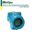
3
Figure 1: RediStart MX Series Model Numbers
RB3-1-S-052A-12C
C = Open Chassis
Frame Size
Amp Rating, (0 - 999A)
Fault Level
S = Standard
H = High
Type of Bypass
0 = None (only available with RC)
1 = Integrated
2 = Separate, Definite Purpose (Only with 1000V Starter)
3 = Separate, ATL IEC AC3 Rated
4 = Separate, ATL NEMA Rated (AC4)
Type of Control
2
2 = MX
3
3 = MX
Family of RediStart Starter
B = Bypass
C = Continuous
5
1 - INTRODUCTION
General Overview of a Reduced Voltage Starter
General Overview
3
The RediStart MX motor starter is a microprocessor-controlled starter for single or three-phase motors. The
starter can be custom designed for specific applications. A few of the features are:
• Solid state design.
• Reduced voltage starting and soft stopping.
• Closed-loop motor current control, power (kW) control, torque control.
• Programmable motor protection.
• Programmable operating parameters.
• Programmable metering.
• Communications
Each starter can operate within applied line voltage and frequency values of 100VAC to 600VAC (optional
1000VAC) and 23 to 72Hz.
The starter can be programmed for any motor FLA and all of the common motor service factors. It enables
3
operators to control both motor acceleration and deceleration. The RediStart MX can also protect the motor
and its load from damage that could be caused by incorrect phase order wiring.
The starter continually monitors the amount of current being delivered to the motor. This protects the motor
from overheating or drawing excess current.
Features
6
The enhanced engineering features of the starter include:
• Multiple frame sizes
• Universal voltage operation
• Universal frequency operation
• Programmable motor overload multiplier
• Controlled acceleration and deceleration
• Phase rotation protection
• Regulated current control
• Electronic motor thermal overload protection
• Electronic over/under current protection
• Single phase protection
• Line-to-line current imbalance protection
• Stalled motor protection
• Programmable metering
• Passcode protected
• Programmable Relays
• Analog output with digital offset and span adjustment
• Analog input with digital offset and span adjustment
• Voltage and Current Accuracy of 3%
• Slow speed (Cyclo Conversion) 1.0 – 40.0% forward and reverse
• Motor winding heater (Anti-Condensation)
• Anti-windmilling brake
• PTC Thermistor
• 99 Event Recorder
• 9 Fault Log
• Real Time Clock
• Zero Sequence Ground Fault
• Backspin Timer
• Starts per Hour
• Time between Starts
• PORT (Power Outage Ride Through)
• 16 RTDs with O/L Biasing
• D.C. Injection Braking (Light or Heavy duty)
2 Technical Specifications
7
2 - TECHNICAL SPECIFICATIONS
Technical Specifications
2.1
General Information
The physical specifications of the starter vary depending upon its configuration. The applicable motor current determines the
configuration and its specific application requirements.
Specifications are subject to change without notice.
This document covers the control electronics and several power sections:
•
•
•
3
MX control card set
RB Power Stacks with Bypass, Integral and Separate
RC Power Stacks, Continuous operation, NO bypass
Electrical Ratings
2.2
Electrical Ratings
2.2.1
Terminal Points and Functions
Table 1: Terminals
Function
Terminal
Block
Terminal Number
Description
Control Power
TB1
G, ground
N, 120VAC neutral
N, 120VAC neutral
L, 120VAC line
L, 120VAC line
96 – 144 VAC input, 50/60 Hz
45VA required for control card
Relay 1 (R1)
TB2
NO1:Normally Open Contact
RC1:Common
NC1: Normally Closed Contact
Relay Output, SPDT form C
NO Contact (resistive)
NC Contact(resistive)
5A at 250VAC
3A at 250VAC
5A at 125VAC
3A at 125VAC
5A at 30VDC
3A at 30VDC
1250VA
750VA
Relay 2 (R2)
TB2
NO2: Normally Open Contact
RC2: Common Contact
NC2: Normally Closed Contact
Relay Output, SPDT form C
NO Contact (resistive)
NC Contact(resistive)
5A at 250VAC
3A at 250VAC
5A at 125VAC
3A at 125VAC
5A at 30VDC
3A at 30VDC
1250VA
750VA
Relay 3 (R3)
TB2
NO3: Normally Open Contact
RC3: Common Contact
NC3: Normally Closed Contact
10A at 250VAC
10A at 125VAC
10A at 30VDC
2500VA
Relay 4 (R4)
J3
R4A: Normally Open Contact
R4B: Normally Open Contact
Relay Output, SPST-NO form A
Resistive:
5A at 250VAC
5A at 125VAC
5A at 30VDC
1250VA
Relay 5 (R5)
J3
R5A: Normally Open Contact
R5B: Normally Open Contact
Relay Output, SPST-NO form A
Resistive:
5A at 250VAC
5A at 125VAC
5A at 30VDC
1250VA
Relay 6 (R6)
J3
R6A: Normally Open Contact
R6B: Normally Open Contact
Relay Output, SPST-NO form A
Resistive:
5A at 250VAC
5A at 125VAC
5A at 30VDC
1250VA
8
2 - TECHNICAL SPECIFICATIONS
Table 1: Terminals
Function
Terminal
Block
Digital Inputs
Terminal Number
Description
TB3
1: Start
2: DI1
3: DI2
4: DI3
5: Common
120VAC digital input
2500V optical isolation
4mA current draw
Off: 0-35VAC
On: 60-120VAC
Digital Inputs
J6
1: DI4
2: DI5
3: DI6
4: DI7
5: DI8
6: Common
120VAC digital input
2500V optical isolation
4mA current draw
Off: 0-35VAC
On: 60-120VAC
Serial Comm
TB4
1: B+
2: A3: COM
Modbus RTU serial communication port.
RS-485 interface
19.2k baud maximum
2500V Isolation
Analog I/O
TB5
1: Ain Power
2: Ain +
3: Ain 4: Common
5: Aout
6: Common
7: Shield
Input:
Voltage or Current
Voltage: 0-10VDC, 67KW impedance
Current: 0-20mA, 500W impedance
Output:
Voltage or Current
Voltage: 0-10VDC, 120mA maximum
Current: 0-20mA, 500W load maximum
PTC Thermistor Input
J7
1: Motor PTC
2: Motor PTC
Positive Temperature Coefficient Thermistor
- Trip resistance 3.5K, ± 300 Ohms.
- Reset resistance 1.65K, ± 150 Ohms.
- Open terminal voltage is 15V.
- PTC voltage at 4Kohms = 8.55V. (>7.5V)
- Response time adjustable between 1 and 5
seconds.
- Maximum cold resistance of PTC chain = 1500
Ohms.
Zero Sequence Ground
Fault
J15
1: CT input
2: CT input
Zero Sequence Ground Fault
CT Type: 50:0.025 (2000:1 ratio)
Measurement range: 0.1A - 25.0 Amps Accuracy : +/- 3%
Burden at 25Amps : 0.0089VA.
Display
RJ45
SCR
J6 to J11
1: Gate
2: Cathode
SCR gate Connections
Phase C.T.
J12
1: CT1+
2: CT1
3: CT2+
4: CT2
5: CT3+
6: CT3
Phase CT Connector
Door Mounted Display Connector
Wire Gauge
The terminals can support 1- 14 AWG wire or 2-16 AWG wires or smaller.
Torque Rating
The terminals on the control cards have a torque rating of 5.0-inch lb. or 0.56Nm. This MUST be
followed or damage will occur to the terminals.
z NOTE: Refer to Control Card Layouts starting on page 41.
9
2 - TECHNICAL SPECIFICATIONS
2.2.2
Measurements and Accuracies
Table 2: Measurements and Accuracies
Internal Measurements
CT Inputs
Line Voltage Inputs
Conversion: True RMS, Sampling @ 1.562kHz
Range: 1-6400A
Conversion: True RMS, Sampling @ 1.562kHz
Range: 100VAC to 1000VAC, 23 to 72 Hz
Metering
Current
Voltage
Watts
Volts-Amps
Watt-Hours
PF
Line Frequency
Ground Fault
Zero Seq GF
Run Time
Analog Input
Analog Output
0 – 40,000 Amps ± 3%
0 – 1250 Volts ± 3%
0 – 9,999 MW ± 5%
0 – 9,999 MVA ± 5%
0 – 10,000 MWh ± 5%
-0.01 to +0.01 (Lag & Lead) ± 5%
23 – 72 Hz ± 0.1 Hz
5 – 100% FLA ± 5% (Machine Protection)
0.1 – 25.0 Amps ± 3%
± 3 seconds per 24 hour period
Accuracy ± 3% of full scale (10 bit)
Accuracy ±2% of full scale (12 bit)
z NOTE: Percent accuracy is percent of full scale of the given ranges, Current = Motor
FLA, Voltage = 1000V, Watts/Volts-Amps/Watt-Hours = Motor & Voltage range
2.2.3
List of Motor Protection Features
•
•
•
•
•
•
•
•
•
•
•
•
•
•
•
•
•
•
•
•
10
ANSI 14 – Speed Switch and Tachometer Trip
ANSI 19 – Reduced Voltage Start
ANSI 27 / 59 – Adjustable over/under voltage protection (Off or 1 to 40%, time 0.1 to 90.0 sec. in 0.1 sec.
intervals, independent over and under voltage levels)
ANSI 37 – Undercurrent detection (Off or 5 to 100% and time 0.1 to 90.0 sec. in 0.1 sec. intervals)
ANSI 38 – Bearing RTD
Other RTD
Open RTD Alarm
ANSI 46 – Current imbalance detection (Off or 5 to 40%)
ANSI 47 – Phase rotation (selectable ABC, CBA, Insensitive, or Single Phase)
ANSI 48 – Adjustable up-to-speed / stall timer (1 to 900 sec. in 1 sec. intervals)
ANSI 49 – Stator RTD
ANSI 50 – Instantaneous electronic overcurrent trip
ANSI 51 – Electronic motor overload (Off, class 1 to 40, separate starting and running curves available)
ANSI 51 – Overcurrent detection (Off or 50 to 800% and time 0.1 to 90.0 sec. in 0.1 sec. intervals)
ANSI 51G – Residual Ground fault detection (Off or 5 to 100% of motor FLA)
Zero Sequence Ground Fault Detection (Off, 0.1 - 25Amps)
ANSI 66 – Starts/Hour & Time Between Starts
Restart Block (Backspin Timer)
ANSI 74 – Alarm relay output available
ANSI 81 – Over / Under Frequency
ANSI 86 – Overload lockout
Single Phase Protection
Shorted SCR detection
Mechanical Jam
2 - TECHNICAL SPECIFICATIONS
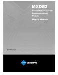
Solid State Motor Overload
3
2
3
The MX control has an advanced I t electronic motor overload (OL) protection function. For optimal motor protection the MX control
has forty standard NEMA style overload curves available for use. Separate overloads can be programmed, one for acceleration and
3
another for normal running operation. The overloads can be individual, the same or completely disabled if necessary. The MX motor
overload function also implements a NEMA based current imbalance overload compensation, RTD Biasing, user adjustable hot and cold
motor compensation and user adjustable exponential motor cooling.
Figure 2: Commonly Used Overload Curves
10000
1000
Seconds to Trip
2.2.4
100
Class 40
Class 35
Class 30
Class 25
Class 20
10
Class 15
Class 10
Class 5
1
100
150
200
250
300
350
400
450
500
550
600
650
700
750
800
Current % (FLA)
The motor overload will NOT trip when the current is less than motor Full Load Amps (FLA) * Service Factor (SF).
The motor overload "pick up" point current is at motor Full Load Amps (FLA) * Service Factor (SF).
The motor overload trip time will be reduced when there is a current imbalance present.
z NOTE: Refer to Theory of Operation, Chapter 7 in section 7.1 for more motor overload details and a larger graph.
Refer to http://www.benshaw.com/olcurves.html for an automated overload calculator.
11
2 - TECHNICAL SPECIFICATIONS
2.2.5
CT Ratios
Table 3: CT Ratios
CT Ratio
Minimum FLA
(A rms)
Maximum FLA
(A rms)
72:1
(4 wraps 288:1)
4
16
96:1
(3 wraps 288:1)
5
21
144:1
(2 wraps 288:1)
8
32
288:1
15
64
864:1
45
190
2640:1
135
590
3900:1
200
870
5760:1
295
1285
8000:1
410
1800
14400:1
(CT-CT combination)
740
3200
28800:1
(CT-CT combination)
1475
6400
For the following CT Ratios, consult factory.
12
50:5
11
45
150:5
33
135
250:5
55
225
800:5
176
720
2000:5
440
1800
5000:5
1100
4500
2 - TECHNICAL SPECIFICATIONS
2.2.6
Optional RTD Module Specifications
The starter has the option of operating with up to two Benshaw SPR-100P remote RTD modules.
Table 4: Remote RTD Module Specifications
Model Number
RTD Type
TCR (a)
SPR-100P
100W Platinum, 3 lead
0.00385 W/W/°C
(DIN 43760)
Maximum Lead Resistance
25W per lead
Recommended Lead Resistance
Less than 16W per lead
Shorted Lead Detection
< 60W
Open Lead Detection
RTD Sensing Current
RTD Sensing Voltage
Range
> 260W
10 mA DC
10V DC maximum
Resolution
1 °C (1.8 °F)
Accuracy
Sampling Rate
Number of RTDs
Input Voltage
Communication Type
Modbus® Addresses
±1.0% full scale (±2 °C or ±3.6 °F)
1 RTD per second
8
Operating Environment
Terminal Strips
Dimensions
Listing
0 to 200 °C (32 to 392 °F)
24 Volts DC ± 20%, 2.5W
Modbus RTU, RS-485, 19.2Kbps
16 to 23
-40 to 60 °C (-40 to 140 °F), up to 95% R.H.,
non-condensing
Accepts one or two stranded copper wires of the same
size from 12 to 30 AWG
5 ½" W x 3 ½" H x 2 ¼" D
cUL
13
2 - TECHNICAL SPECIFICATIONS
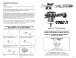
2.2.7
Zero Sequence Ground Fault CT
The Benshaw BICT 2000/1-6 CT has the following excitation curve.
Figure 3: BICT2000/1-6 Excitation Curve
Starter Power Ratings
2.3
Starter Power Ratings
Each RB3 model starter is rated for three different starting duties. For example, a starter can operate a:
300HP motor for a standard duty start (350% for 30 seconds)
Or
200HP for a heavy duty start (500% for 30 seconds)
Or
150HP motor for a class 30 start (600% for 30 seconds)
Or
450HP motor when connected to the inside delta of a motor for a class 10 start (350% for 30 seconds)
14
2 - TECHNICAL SPECIFICATIONS
2.3.1
Standard Duty (350% for 30 sec) Ratings
Table 5: Standard Duty Horsepower Ratings
Standard Duty
(350% current for 30 seconds, 115% Continuous)
NOMINAL
AMPS
HORSEPOWER RATING
200-208V
230-240V
380-400V
440-480V
575-600V
RB3-1-S-027A-11C
27
7.5
10
15
20
25
RB3-1-S-040A-11C
40
10
15
25
30
40
RB3-1-S-052A-12C
52
15
20
30
40
50
RB3-1-S-065A-12C
65
20
25
40
50
60
RB3-1-S-077A-13C
77
25
30
40
60
75
RB3-1-S-096A-13C
96
30
40
50
75
100
RB3-1-S-125A-14C
125
40
50
75
100
125
RB3-1-S-156A-14C
156
50
60
75
125
150
RB3-1-S-180A-14C
180
60
75
100
150
200
RB3-1-S-180A-15C
180
60
75
100
150
200
RB3-1-S-240A-15C
240
75
100
150
200
250
RB3-1-S-302A-15C
302
100
125
150
250
300
RB3-1-S-361A-16C
361
125
150
200
300
400
RB3-1-S-414A-17C
414
150
150
250
350
400
RB3-1-S-477A-17C
477
150
200
300
400
500
RB3-1-S-515A-17C
515
200
200
300
450
500
RB3-1-S-590A-18C
590
200
250
350
500
600
RB3-1-S-720A-19C
720
250
300
400
600
700
RB3-1-S-838A-20C
838
300
350
500
700
800
MODEL NUMBER
z NOTE: Do not exceed Class 10 overload setting.
15
2 - TECHNICAL SPECIFICATIONS
2.3.2
Heavy Duty (500% current for 30 sec) Ratings
Table 6: Heavy Duty Horsepower Ratings
Heavy Duty
(500% current for 30 seconds, 125% Continuous)
HORSEPOWER RATING
NOMINAL
AMPS
200-208V
230-240V
380-400V
440-480V
575-600V
RB3-1-S-027A-11C
24
7.5
10
15
20
25
RB3-1-S-040A-11C
40
10
15
25
30
40
RB3-1-S-052A-12C
54
15
20
30
40
50
RB3-1-S-065A-12C
54
15
20
30
40
50
RB3-1-S-077A-13C
54
15
20
30
40
50
RB3-1-S-096A-13C
96
30
40
50
75
100
RB3-1-S-125A-14C
125
40
50
75
100
125
RB3-1-S-156A-14C
125
40
50
75
100
125
RB3-1-S-180A-14C
125
40
50
75
100
125
RB3-1-S-180A-15C
180
60
75
100
150
200
RB3-1-S-240A-15C
215
60
75
125
150
200
RB3-1-S-302A-15C
215
60
75
125
150
200
RB3-1-S-361A-16C
252
75
100
150
200
250
RB3-1-S-414A-17C
372
125
150
200
300
400
RB3-1-S-477A-17C
372
125
150
200
300
400
RB3-1-S-515A-17C
372
125
150
200
300
400
RB3-1-S-590A-18C
551
200
200
300
450
500
RB3-1-S-720A-19C
623
200
250
350
500
600
RB3-1-S-838A-20C
623
200
250
350
500
600
MODEL NUMBER
z NOTE: Do not exceed Class 20 overload setting.
16
2 - TECHNICAL SPECIFICATIONS
2.3.3
Severe Duty (600% current for 30 sec) Ratings
Table 7: Severe Duty Horsepower Ratings
Severe Duty
(600% current for 30 seconds 125% Continuous)
HORSEPOWER RATING
NOMINAL
AMPS
200-208V
230-240V
380-400V
440-480V
575-600V
RB3-1-S-027A-11C
24
5
7.5
10
15
20
RB3-1-S-040A-11C
40
10
10
20
30
40
RB3-1-S-052A-12C
45
10
15
25
30
40
RB3-1-S-065A-12C
45
10
15
25
30
40
RB3-1-S-077A-13C
45
10
15
25
30
40
RB3-1-S-096A-13C
77
25
30
40
60
75
RB3-1-S-125A-14C
105
30
40
60
75
100
RB3-1-S-156A-14C
105
30
40
60
75
100
RB3-1-S-180A-14C
105
30
40
60
75
100
RB3-1-S-180A-15C
180
50
60
100
125
150
RB3-1-S-240A-15C
180
50
60
100
125
150
RB3-1-S-302A-15C
180
50
60
100
125
150
RB3-1-S-361A-16C
210
60
75
125
150
200
RB3-1-S-414A-17C
310
100
125
150
250
300
RB3-1-S-477A-17C
310
100
125
150
250
300
RB3-1-S-515A-17C
310
100
125
150
250
300
RB3-1-S-590A-18C
515
150
200
300
450
500
RB3-1-S-720A-19C
515
150
200
300
450
500
RB3-1-S-838A-20C
515
150
200
300
450
500
MODEL NUMBER
z NOTE: Do not exceed Class 30 overload setting.
17
2 - TECHNICAL SPECIFICATIONS
2.3.4
Inside Delta Connected Standard Duty (350% for 30 sec) Ratings
Table 8: Inside Delta Standard Duty Horsepower Ratings
INSIDE DELTA Std Duty
(350% start for 30 seconds 115% Continuous)
HORSEPOWER RATING
NOMINAL
AMPS
200-208V
220-240V
380-415V
440-480V
575-600V
RB3-1-S-125A-14C
180
60
75
100
150
200
RB3-1-S-156A-14C
240
75
100
150
200
250
RB3-1-S-180A-14C
279
75
100
150
200
250
RB3-1-S-180A-15C
279
75
100
150
200
250
RB3-1-S-240A-15C
361
125
150
200
300
400
RB3-1-S-302A-15C
414
150
150
250
350
400
RB3-1-S-361A-16C
515
200
150
250
450
400
RB3-1-S-414A-17C
590
200
250
350
500
600
RB3-1-S-477A-17C
720
250
300
400
600
700
RB3-1-S-515A-17C
800
250
300
500
600
700
RB3-1-S-590A-18C
838
300
350
500
700
800
RB3-1-S-720A-19C
1116
300
350
700
900
800
RB3-1-S-838A-20C
1300
400
500
800
1000
1200
MODEL NUMBER
z NOTE: Do not exceed Class 10 overload setting.
18
590
720
838
RB_1_720A18C
RB_1_838A19C
964
828
679
592
549
476
415
347
276
207
207
179
144
110
89
75
60
46
31
1299
1116
915
798
739
642
560
468
372
279
279
242
194
-
-
-
-
-
-
1494
1283
1052
918
850
738
643
538
428
321
321
278
223
171
137
116
93
71
48
42
42
42
42
42
42
30
30
30
30
18
18
18
10
10
10
10
5
5
65
65
65
65
65
65
65
65
65
65
30
30
30
10
10
10
10
5
5
5 For higher kAIC ratings, consult factory
4 Bus Tab with NEMA 2 hole pattern ½" diameter ¾" apart as defined by NEMA Standard CC1
3 Bus Tab with 1 hole ¼" diameter
2 Power Block wire size #10-#1awg
1 Power Block wire size #12-#4awg
* Rating for Inside Delta Application
515
240
RB_1_240A15C
RB_1_590A18C
180
RB_1_180A15C
RB_1_515A17C
180
RB_1_180A14C
477
156
RB_1_156A14C
RB_1_477A17C
125
RB_1_125A14C
414
96
RB_1_096A13C
RB_1_414A17C
77
RB_1_077A13C
302
65
RB_1_065A12C
361
52
RB_1_052A12C
RB_1_302A15C
40
RB_1_040A11C
RB_1_361A16C
27
RB_1_027A11C
Model Number
Unit
Unit
Nominal
115%
Withstand Withstand
Current (A) Current (A)
Rating (KA) Rating (KA)
Inside Delta Inside Delta
Std. Fault5 High. Fault5
Load
2
2
4
4
Bus Tab
4
4
Bus Tab
Bus Tab4
4
4
Bus Tab4
Bus Tab
Bus Tab
Bus Tab
4
Bus Tab4
4
4
4
4
J/T/RK1/RK5/L
J/T/RK1/RK5
J/T/RK1/RK5
J/T/RK1/RK5
J/T/RK1/RK5
J/T/RK1/RK5
J/T/RK1/RK5
J/T/RK1/RK5
J/T/RK1/RK5
J/T/RK1/RK5
J/T/RK1/RK5
J/T/RK1/RK5
Allowable Fuse
Class
L
L
L
L
L/T
L/T
Bus Tab4 J/T/RK1/RK5/L
Bus Tab
Bus Tab
Bus Tab
Bus Tab4
Bus Tab
Bus Tab
Bus Tab
4
Bus Tab4
Bus Tab
Bus Tab
Bus Tab
4
4
4
4
Bus Tab
Bus Tab
Bus Tab
Bus Tab4
4
4
Bus Tab4
Bus Tab
Bus Tab
Bus Tab
3
3
3
3
Bus Tab3
Bus Tab
Bus Tab
Bus Tab
3
Bus Tab3
Power Block
Power Block
Power Block
1
Power Block1 Bus Tab3
Line
Connection Type
1400/2000*
1200/1800*
1000/1600*
900/1300*
800/1200*
700/1100*
600/900*
500/800*
400/600*
300/450*
300/450*
250/400*
200/300*
150/250*
125/200*
110/175*
90/125*
70/100*
45/70*
2000/3000*
1800/2500*
1400/2000*
1300/2000*
1200/1800*
1000/1600*
900/1300*
700/1100*
600/900*
450/700*
450/700*
350/600*
300/450*
225/350*
175/300*
150/250*
125/200*
100/150*
60/100*
Maximum
Maximum
Circuit
Fuse Size
Breaker Trip
Current (A)
Rating (A)
245
205
165
140
120
103
92
82
75
71
71
66
62
59
56
53.7
51
49.8
49
Running Watt
Loss, After
Bypassed
(W)
2.3.5
115%
Nominal
Current
Current
Rating
(A)
(A)
2 - TECHNICAL SPECIFICATIONS
RB3 Power Stack Ratings and Protection Requirements
19
20
302
361
414
477
515
RB_2_302A15C
RB_2_361A16C
RB_2_414A17C
RB_2_477A17C
RB_2_515A17C
964
828
679
592
549
476
415
347
276
207
207
179
144
110
89
75
60
46
31
1299
1116
915
798
739
642
560
468
372
279
279
242
194
-
-
-
-
-
-
1494
1283
1052
918
850
738
643
538
428
321
321
278
223
-
-
-
-
-
-
Consult Factory
30
30
30
30
30
30
18
18
10
10
10
10
10
10
10
5
5
5
Bus Tab4
Consult
Factory
5 For higher kAIC ratings, consult factory
Bus Tab
Bus Tab4
4
4
Bus Tab4
Bus Tab4
Bus Tab
Bus Tab
4
4
Bus Tab
Bus Tab4
4
4
Bus Tab4
Bus Tab
Bus Tab
Bus Tab
Bus Tab4
4
4
Bus Tab4
Bus Tab
Bus Tab
Bus Tab
4
4
4
4
Bus Tab
Bus Tab
Bus Tab
Bus Tab4
4
4
Bus Tab4
Bus Tab
Bus Tab
Bus Tab
4
4
Bus Tab
3
Bus Tab3
Bus Tab
Bus Tab
Bus Tab3
3
Power Block
L
L
L
L
L/T
L/T
J/T/RK1/RK5/L
J/T/RK1/RK5/L
J/T/RK1/RK5
J/T/RK1/RK5
J/T/RK1/RK5
J/T/RK1/RK5
J/T/RK1/RK5
J/T/RK1/RK5
J/T/RK1/RK5
J/T/RK1/RK5
J/T/RK1/RK5
Power Block2 Bus Tab3
3
J/T/RK1/RK5
2
J/T/RK1/RK5
Power Block1 Bus Tab3
Load
1400/2000*
1200/1800*
1000/1600*
900/1300*
800/1200*
700/1100*
600/900*
500/800*
400/600*
300/450*
300/450*
250/400*
200/300*
150/250*
125/200*
110/175*
90/125*
70/100*
45/70*
2000/3000*
1800/2500*
1400/2000*
1300/2000*
1200/1800*
1000/1600*
900/1300*
700/1100*
600/900*
450/700*
450/700*
350/600*
300/450*
225/350*
175/300*
150/250*
125/200*
100/150*
60/100*
245
205
165
140
120
103
92
82
75
71
71
66
62
59
56
53.7
51
49.8
49
Running
Maximum
Maximum
Watt Loss,
Allowable Fuse
Fuse Size Circuit Breaker
After
Class
Current (A) Trip Rating (A) Bypassed
(W)
Power Block1 Bus Tab3
Line
Connection Type
30
30
30
30
30
30
30
18
18
18
18
10
10
10
10
10
10
5
NEMA (AC4)
Unit Withstand
Fault Rating
(KA) 5
4 Bus Tab with NEMA 2 hole pattern ½" diameter ¾" apart as defined by NEMA Standard CC1
3 Bus Tab with 1 hole ¼" diameter
2 Power Block wire size #10-#1awg
1 Power Block wire size #12-#4awg
* Rating for Inside Delta Application
838
240
RB_2_240A15C
RB_2_838A19C
180
RB_2_180A15C
590
180
RB_2_180A14C
720
156
RB_2_156A14C
RB_2_590A18C
125
RB_2_125A14C
RB_2_720A18C
77
65
RB_2_065A12C
96
52
RB_2_052A12C
RB_2_096A13C
40
RB_2_040A11C
RB_2_077A13C
27
AC3 Unit
Withstand
Fault Rating
(KA) 5
2.3.6
RB_2_027A11C
Model Number
115%
Nominal
Nominal
115%
Current
Current
Current (A) Current (A)
Rating
(A)
Inside Delta Inside Delta
(A)
2 - TECHNICAL SPECIFICATIONS
Power Stack Input Ratings with Protection Requirements for Separate Bypass
156
180
240
302
361
477
590
720
840
960
1200
RC_ 0 _156A14C
RC_ 0 _180A15C
RC_ 0 _240A15C
RC_ 0 _302A15C
RC_ 0 _361A16C
RC_ 0 _477A17C
RC_ 0 _590A18C
RC_ 0 _720A18C
RC_ 0 _840A19C
RC_ 0 _960A19C
RC_ 0_1200KA19C
1440
1200
1050
900
737
596
421
377
300
2225
195
155
155
120
96
81
65
50
33.75
4 For higher kAIC ratings, consult factory
1 Power Block wire size #6 awg max
2 Power Block wire size #2 awg max
3 Power Block wire size #2/0 max
125
RC_ 0 _125A14C
77
RC_ 0 _077A13C
96
65
RC_ 0 _065A12C
124
52
RC_ 0 _052A12C
RC_ 0 _124A33C
40
RC_ 0 _040A11C
RC_ 0 _096A13C
27
85
85
85
42
42
42
42
42
42
42
42
42
42
42
42
42
42
42
42
Power Block
Power Block
Power Block
1
Bus Tab
Bus Tab
Bus Tab
Bus Tab
Bus Tab
Bus Tab
Bus Tab
Bus Tab
Bus Tab
Bus Tab
Bus Tab
Bus Tab
Bus Tab
Bus Tab
Bus Tab
Bus Tab
Bus Tab
Bus Tab
Bus Tab
Bus Tab
Bus Tab
Bus Tab
Bus Tab
Bus Tab
Power Block1 Power Block1
1
Power Block1 Power Block1
Power Block
1
L
L
L
L
L
J/600V AC T/RK1
J/600V AC T/RK1
J/600V AC T/RK1
J/600V AC T/RK1
J/600V AC T/RK1
J/600V AC T/RK1
J/600V AC T/RK1
J/600V AC T/RK1
J/600V AC T/RK1
J/600V AC T/RK1
J/600V AC T/RK1
J/600V AC T/RK1
Power Block2 Power Block1
2
J/600V AC T/RK1
Power Block1 Power Block1
Allowable Fuse
Class
J/600V AC T/RK1
Load
100kA
50kA
100kA
50kA
60
100
60
100
100kA
100kA
50kA
100kA
50kA
1600
2000
1600
2000
100kA
100kA
100kA
100kA
100kA
100kA
100kA
100kA
100kA
100kA
100kA
100kA
1600
1600
1400
800
800
800
600
400
400
350
225
225
225
100kA
100kA
50kA
40
60
225
Short
Circuit
Rating
Maximum Fuse
Current (A)
Current Limiting Circuit Breaker Protected
Rating
Power Block1 Power Block1
Line
Connection Type
400A
600A
800A
1200a
800A
1200A
800A
1200A
CJD63B
CLD63b
CND63B
CND63b
CND63B
CND63b
CND63B
CND63b
HPD63F160
1200 –
1600A
1200 –
1600A
400A
600A
CJD63B
CLD63b
HPD63F160
400A
400A
250A
225A
225A
225A
225A
125A
100A
100A
60A
60A
Trip Plug
CFD63B
CFD63B
CFD63B
CFD63B
CFD63B
CFD63B
CFD63B
CED63B
CED63B
CED63B
CED63B
CED63B
Catalog
Number
85kA
85kA
85kA
85kA
85kA
65kA
65kA
65kA
65kA
65kA
65kA
42kA
42kA
42kA
42kA
42kA
42kA
42Ka
42kA
Short
Circuit
Rating
Current Limiting Circuit Breaker
Protected Rating
3045
2445
2145
1845
1520
1240
950
800
645
495
435
360
360
285
240
210
175
145
110
Running
Watt Loss,
After
Bypassed
(W)
2.3.7
RC_ 0 _027A11C
Model Number
Unit
Nominal
Withstand
125%
Current
Fault
Current
Rating
(A)
(kA)4
2 - TECHNICAL SPECIFICATIONS
Power Stack Input Ratings with Protection Requirements for RC No Bypass
21
2 - TECHNICAL SPECIFICATIONS
2.3.8
RB3 Starter Control Power Requirements
Table 9: RB3 Starter CPT VA Requirements
Model Number
Power
Required
(VA)
Recommended
Min. TX size
Model Number
Power
Required
(VA)
Recommended
Min. TX size
RB3-1-S-027A-11C
74
75
RB3-1-S-240A-15C
243
250
RB3-1-S-040A-11C
74
75
RB3-1-S-302A-15C
243
250
RB3-1-S-052A-12C
111
125
RB3-1-S-361A-16C
243
250
RB3-1-S-065A-12C
111
125
RB3-1-S-414A-17C
441
450
RB3-1-S-077A-13C
111
125
RB3-1-S-477A-17C
441
450
RB3-1-S-096A-13C
111
125
RB3-1-S-515A-17C
441
450
RB3-1-S-125A-14C
131
150
RB3-1-S-590A-18C
441
450
RB3-1-S-156A-14C
243
250
RB3-1-S-720A-19C
441
450
RB3-1-S-180A-14C
243
250
RB3-1-S-838A-20C
243
250
2.3.9
RC3 Starter Control Power Requirements
Table 10: RC3 Starter CPT VA Requirements
Model Number
Power
Required
(VA)
Recommended
Min. TX size
Model Number
Power
Required
(VA)
Recommended
Min. TX size
RC3-1-S-027A-31C
45
75
RC3-1-S-240A-35C
123
150
RC3-1-S-040A-31C
45
75
RC3-1-S-302A-35C
123
150
RC3-1-S-052A-31C
45
75
RC3-1-S-361A-35C
201
250
RC3-1-S-065A-32C
45
75
RC3-1-S-414A-35C
150
200
RC3-1-S-077A-32C
45
75
RC3-1-S-477A-35C
225
350
RC3-1-S-096A-33C
45
75
RC3-1-S-590A-35C
225
350
RC3-1-S-124A-33C
45
75
RC3-1-S-720A-36C
225
350
RC3-1-S-125A-34C
123
150
RC3-1-S-840A-19C
225
350
RC3-1-S-156A-34C
123
150
RC3-1-S-960A-20C
225
350
RC3-1-S-180A-34C
123
150
RC3-1-S-1200A-37C
285
350
22
2 - TECHNICAL SPECIFICATIONS
Mechanical Drawings
2.4
Dimensions
2.4.1
RB3 Chassis with Integral Bypass
Figure 4: RB3 - 96A, 830A
Model
A
B
C
D
E
F
RB3 27-65A
14
10
12.5
8.43
0.84
0.31
RB3 77-96A
15
10
13.5
8.43
0.84
0.31
RB3 838A
27.75
26.6
23.5
8.7
N/A
0.31
A
B
C
D
E
F
RB3 125A
19.5
12.27
13.25
4
0.5
0.31
RB3 156-180A
21.25
12.27
15.25
4
0.5
0.31
RB3 180-302A
22.75
12.27
16.75
4
0.5
0.31
RB3 361A
23.87
13.09
18.63
4.31
0.5
0.31
Figure 5: RB3 125 - 361A
Model
23
2 - TECHNICAL SPECIFICATIONS
Figure 6: RB3 414 - 838A
A
B
C
D
E
F
RB3 414-590A
28.29
18.5
26.25
6
N/A
0.31
RB3 720A
30.04
18.5
28
6
N/A
0.31
RB3 838A
27.75
26.6
23.5
8.7
N/A
0.31
Model
2.4.2
RC3 Chassis with no Bypass
Figure 7: RC3 0 - 124A
24
Model
A
B
C
D
E
RC3 27-52A
14
9.875
3.375
4.69
8-32 TAP
RC3 65-77A
18
10
4.375
4.75
¼-20 TAP
RC3 96-124A
27
10
5.313
4.75
¼-20 TAP
2 - TECHNICAL SPECIFICATIONS
Figure 8: RC3 156 - 590A
Model
A
B
C
D
E
RC3 156-180A
18
15
17
13.5
0.3
RC3 240A
24
15
23
13.5
0.5
RC3 302-361A
28
17.25
27
15.75
0.5
RC3 477A
28
20
27
18.5
0.5
RC3 590A
35
20
34
18.5
0.5
Environmental Conditions
2.5
Environmental Conditions
Table 11: Environmental Ratings
Operating Temperatures
-10°C to +40°C (14°F to 104°F)enclosed
-10°C to +50°C (14°F to 122°F)open
Storage Temperatures
-20°C to +70°C (-4°F to 155°F)
Humidity
0% to 95% non condensing
Altitude
1000m (3300ft) without derating
Maximum Vibration
5.9m/s2 (19.2ft/s2 ) [0.6G]
Cooling
RC (Natural convection)
RB (Bypassed)
25
2 - TECHNICAL SPECIFICATIONS
Altitude Derating
2.6
Altitude Derating
Benshaw's starters are capable of operating at altitudes up to 3,300 feet (1000 meters) without requiring altitude derating. Table 12
provides the derating percentage to be considered when using a starter above 3,300 feet (1000 meters).
Table 12: Altitude Derating
Altitude
Percent Derating (Amps)
3300 Feet
1006 meters
0.0%
4300 Feet
1311 meters
3.0%
5300 Feet
1615 meters
6.0%
6300 Feet
1920 meters
9.0%
7300 Feet
2225 meters
12.0%
8300 Feet
2530 meters
15.0%
9300 Feet
2835 meters
18.0%
Real Time Clock
2.7
Real Time Clock
3
The MX comes with a real time clock. The user can enter the actual time and the starter will use this time when it logs faults in the fault
recorder as well as events in the event recorder. This can help with troubleshooting. The system clock does not recognize daylight
savings time.
Accuracy: +- 1 minute per month
Range: 1/1/1972 to 1/1/2107 with automatic leap year compensation.
Approvals
2.8
Approvals
3
MX Control Card set is UL, cUL Recognized
Certificate of Compliance
2.9
Certificate of Compliance
CE Mark, See Appendix E on page 208.
26
3
Installation
27
3 - INSTALLATION
Before You Start
3.1
Before You Start
3.1.1
Installation Precautions
Inspection
3
Before storing or installing the RediStart MX Series Starter, thoroughly inspect the device for possible shipping damage. Upon receipt:
• Remove the starter from its package and inspect exterior for shipping damage. If damage is apparent, notify the shipping agent and
your sales representative.
• Open the enclosure and inspect the starter for any apparent damage or foreign objects. Ensure that all of the mounting hardware and
terminal connection hardware is properly seated, securely fastened, and undamaged.
• Ensure all connections and wires are secured.
• Read the technical data label affixed to the starter and ensure that the correct horsepower and input voltage for the application has
been purchased.
The numbering system for a chassis is shown below.
General Information
Installation of some models may require halting production during installation. If applicable, ensure that the starter is installed when
production can be halted long enough to accommodate the installation. Before installing the starter, ensure:
• The wiring diagram (supplied separately with the starter) is correct for the required application.
• The starter is the correct current rating and voltage rating for the motor being started.
• All of the installation safety precautions are followed.
• The correct power source is available.
• The starter control method has been selected.
• The connection cables have been obtained (lugs) and associated mounting hardware.
• The necessary installation tools and supplies are procured.
• The installation site meets all environmental specifications for the starter NEMA/CEMA rating.
• The motor being started has been installed and is ready to be started.
• Any power factor correction capacitors (PFCC) are installed on the power source side of the starter and not on the motor side.
Failure to remove power factor correction or surge capacitors from the load side of the starter will result in serious damage to the starter
that will not be covered by the starter warranty. The capacitors must be connected to the line side of the starter. The up-to-speed (UTS)
contact can be used to energize the capacitors after the motor has reached full speed.
3.1.2
Safety Precautions
To ensure the safety of the individuals installing the starter, and the safe operation of the starter, observe the following guidelines:
• Ensure that the installation site meets all of the required environmental conditions (Refer to Site Preparation, page 29).
• LOCK OUT ALL SOURCES OF POWER.
• Install circuit disconnecting devices (i.e., circuit breaker, fused disconnect or non-fused disconnect) if they were not previously
installed by the factory as part of the package.
• Install short circuit protection (i.e., circuit breaker or fuses) if not previously installed by the factory as part of the package.
• Consult Power Ratings for the fault rating on pages 19-21.
• Follow all NEC (National Electrical Code) and/or C.S.A. (Canadian Standards Association) standards or Local Codes as applicable.
• Remove any foreign objects from the interior of the enclosure, especially wire strands that may be left over from installation wiring.
• Ensure that a qualified electrician installs wiring.
• Ensure that the individuals installing the starter are wearing ALL protective eyewear and clothing.
• Ensure the starter is protected from debris, metal shavings and any other foreign objects.
The opening of the branch circuit protective device may be an indication that a fault current has been interrupted. To reduce the risk of
electrical shock, current carrying parts and other components of the starter should be inspected and replaced if damaged.
28
3 - INSTALLATION
Installation Considerations
3.2
Installation Considerations
3.2.1
Site Preparation
General Information
Before the starter can be installed, the installation site must be prepared. The customer is responsible for:
• Providing the correct power source
• Providing the correct power protection
• Selecting the control mechanism
• Obtaining the connection cables, lugs and all other hardware
• Ensuring the installation site meets all environmental specifications for the enclosure NEMA rating
• Installing and connecting the motor
Power Cables
The power cables for the starter must have the correct NEC/CSA current rating for the unit being installed. Depending upon the model,
the power cables can range from a single #14 AWG conductor to four 750 MCM cables. (Consult local and national codes for selecting
wire size).
Site Requirements
The installation site must adhere to the applicable starter NEMA/CEMA rating. For optimal performance, the installation site must meet
the appropriate environmental and altitude requirements.
3.2.2
3.2.3
EMC Installation Guidelines
General
In order to help our customers comply with European electromagnetic compatibility standards, Benshaw Inc. has
developed the following guidelines.
Attention
This product has been designed for Class A equipment. Use of the product in domestic environments may cause radio
interference, in which case the installer may need to use additional mitigation methods.
Enclosure
Install the product in a grounded metal enclosure.
Grounding
Connect a grounding conductor to the screw or terminal provided as standard on each controller. Refer to layout/power
wiring schematic for grounding provision location.
Wiring
Refer to Wiring Practices on page 31.
Filtering
To comply with Conducted Emission Limits (CE requirement), a high voltage (1000V or greater) 0.1 uF capacitor
should be connected from each input line to ground at the point where the line enters the cabinet.
Use of Power Factor Capacitors
Power factor correction capacitors and surge capacitors CAN NOT be connected between the starter and the motor. These devices can
damage the SCRs during ramping. These devices appear like a short circuit to the SCR when it turns on, which causes a di/dt level
greater than the SCR can handle. If used, power factor correction capacitors or surge capacitors must be connected ahead of the starter
and sequenced into the power circuit after the start is completed. A programmable relay can be configured as an up-to-speed (UTS) relay
and then used to pull-in a contactor to connect the capacitors after the motor has reached full speed.
z NOTE: If the motor manufacturer supplies surge capacitors they must be removed before starting.
3.2.4
Use of Electro-Mechanical Brakes
If an electro-mechanical brake is used with the starter, it must be powered from the line side of the starter to ensure full voltage is applied
to the brake during a start so it will properly release. A programmable relay can be configured as a run relay and then used to pull-in a
contactor to power the brake whenever the starter is providing power to the motor.
3.2.5
Reversing Contactor
If the application requires a reversing contactor, it should be connected on the output side (load) of the soft starter. The contactor must
be closed before starting the soft starter. The soft starter must be off before switching the direction of the reversing contactor. The
reversing contactor must never be switched while the soft starter is operating.
29
3 - INSTALLATION
Mounting Considerations
3.3
Mounting Considerations
3.3.1
Bypassed Starters
Provisions should be made to ensure that the average temperature inside the enclosure never rises above 50°C. If the temperature inside
the enclosure is too high, the starter can be damaged or the operational life can be reduced.
3.3.2
Non-Bypassed Starters
Provisions should be made to ensure that the temperature inside the enclosure never rises above 50°C. If the temperature inside the
enclosure is too high, the starter can be damaged or the operational life can be reduced. As a general rule of thumb, the following
ventilation guidelines can be followed.
Table 13: Ventilation Requirements
Current Range
< 200 amps
Bottom of Enclosure
Fans or grills depending on enclosure size
Top of Enclosure
200 to 300 amps
301 to 400 amps
401 to 600 amps
601 to 700 amps
> 700 amps
2 x 4” grills (12 sq. in.)
1 x 4” fan (115 cfm)
2 x 4” fan (230 cfm)
2 x 6” fan (470 cfm)
Consult factory
2 x 4” grills (12 sq.in.)
2 x 4” grills (12 sq.in.)
2 x 6” grills (28 sq.in.)
2 x 6” grills (28 sq.in.)
Consult Factory
The starter produces 4 watts of heat per amp of current and 26 square inches of enclosure surface is required per watt of heat generation.
Contact Benshaw and ask for the enclosure sizing technical note for more information concerning starters in sealed enclosures. Benshaw
supplies starters under 124 amps non-bypassed, with the heat sink protruding from the back of the enclosure. This allows a small
enclosure size while still maintaining the cooling capability of the starter.
30
3 - INSTALLATION
Wiring Considerations
3.4
Wiring Considerations
3.4.1
Wiring Practices
When making power and control signal connections, the following should be observed:
• Never connect input AC power to the motor output terminals T1/U, T2/V, or T3/W.
• Power wiring to the motor must have the maximum possible separation from all other wiring. Do not run control wiring in the same
conduit; this separation reduces the possibility of coupling electrical noise between circuits. Minimum spacing between metallic
conduits containing different wire groups should be three inches (8cm).
• Minimum spacing between different wiring groups in the same tray should be six inches.
• Wire runs outside an enclosure should be run in metallic conduit or have shielding/armor with equivalent attenuation.
• Whenever power and control wiring cross it should be at a 90 degrees angle.
• Different wire groups should be run in separate conduits.
• With a reversing application, the starter must be installed in front of the reversing contactors.
z NOTE: Local electrical codes must be adhered to for all wiring practices.
3.4.2
Considerations for Control and Power Wiring
Control wiring refers to wires connected to the control terminal strip that normally carry 24V to 115V and Power wiring refers to wires
connected to the line and load terminals that normally carries 200VAC - 600VAC respectively. Select power wiring as follows:
• Use only UL or CSA recognized wire.
• Wire voltage rating must be a minimum of 300V for 230VAC systems and 600V (Class 1 wire) for 460VAC and 600VAC systems.
• Grounding must be in accordance with NEC, CEC or local codes. If multiple starters are installed near each other, each must be
connected to ground. Take care to not form a ground loop. The grounds should be connected in a STAR configuration.
• Wire must be made of copper and rated 60/75°C for units 124 Amps and below. Larger amp units may use copper or aluminum wire.
Refer to NEC table 310-16 or local codes for proper wire selection.
3.4.3
Considerations for Signal Wiring
Signal wiring refers to the wires connected to the control terminal strip that are low voltage signals, below 15V.
• Shielded wire is recommended to prevent electrical noise interference from causing improper operation or nuisance tripping.
• Signal wire rating should carry as high of a voltage rating as possible, normally at least 300V.
• Routing of signal wire is important to keep as far away from control and power wiring as possible.
3.4.4
Meggering a Motor
If the motor needs to be meggered, remove the motor leads from the starter before conducting the test. Failure to comply may damage the
SCRs and WILL damage the control board, which WILL NOT be replaced under warranty.
3.4.5
High Pot Testing
If the starter needs to be high pot tested, perform a DC high pot test. The maximum high point voltage must not exceed 2.0 times rated
RMS voltage + 1000VAC (High pot to 75% of Factory). Failure to comply WILL damage the control board, which WILL NOT be
replaced under warranty. An example to find the high point voltage is (2.0 * rated RMS voltage + 1000) * 0.75.
31
3 - INSTALLATION
Power and Control Drawings for Bypassed and Non Bypassed Power Stacks
3.5
Power and Control drawings for Bypassed and Non Bypassed Power Stacks
Figure 9: Power Schematic for RB3 Low HP
BIPC-400100-01
MX3 CARD ASSEMBLY
CONSISTS OF BIPC-300055-03 (TOP)
& BIPC-300034-02 (BOTTOM)
stop
reset
START
menu
enter
Starters
32
3 - INSTALLATION
Figure 10: Power Schematic for RB3 High HP
BIPC-400100-01
MX3 CARD ASSEMBLY
CONSISTS OF BIPC-300055-03 (TOP)
& BIPC-300034-02 (BOTTOM)
stop
reset
START
menu
enter
Starters
33
3 - INSTALLATION
Figure 11: Power Schematic for RC3
BIPC-400100-01
MX3 CARD ASSEMBLY
CONSISTS OF BIPC-300055-03 (TOP)
& BIPC-300034-02 (BOTTOM)
stop
reset
START
menu
enter
Starters
34
3 - INSTALLATION
Power Wiring
3.6
Power Wiring
3.6.1
Recommended Incoming Line Protection
Fuses or Circuit Breaker, refer to pages 19 - 21.
Input Line Requirements
The input line source needs to be an adequate source to start the motor, generally 2 times the rating of the motor FLA. (This may not
apply in some cases such as being connected to a generator).
3.6.2
Recommended Wire Gauges
The wire gauge selection is based on the FLA of the motor. Refer to NEC table 310-16 or CEC Part 1, Table 2 or local code
requirements for selecting the correct wire sizing. Ensure appropriate wire derating for temperature is applied. If more than three current
carrying conductors are in one conduit, ensure NEC table 310.15(B)(2) or CEC Part 1 Table 5C is adhered to. In some areas local codes
may take precedence over the NEC. Refer to your local requirements.
3.6.3
Power Wire Connections
Attach the motor cables:
• Use the T1, T2 and T3 terminals. Use lugs/crimps or terminals. (Lugs and Crimps are to be provided by the user)
Attach the power source cables:
• Use the L1, L2 and L3 terminals. Use lugs/crimps or terminals (Lugs and Crimps are to be provided by the user).
3.6.4
Motor Lead Length
The standard starter can operate a motor with a maximum of 2000 feet of properly sized cable between the “T” leads of the starter and
that of the motor. For wire runs greater than 2000 feet contact Benshaw Inc. for application assistance. If shielded cable is used, consult
factory for recommended length.
35
3 - INSTALLATION
3.6.5
Compression Lugs
The following is a list of the recommended crimp-on wire connectors manufactured by Penn-Union Corp. for copper wire.
Table 14: Single Hole Compression Lugs
Wire Size
1/0
Part #
BLU-1/0S20
Wire Size
500 MCM
Part #
BLU-050S2
2/0
3/0
4/0
BLU-2/0S4
BLU-3/0S1
BLU-4/0S1
600 MCM
650 MCM
750 MCM
BLU-060S1
BLU-065S5
BLU-075S
250 MCM
300 MCM
350 MCM
BLU-025S
BLU-030S
BLU-035S
800 MCM
1000 MCM
1500 MCM
BLU-080S
BLU-100S
BLU-150S
400 MCM
450 MCM
BLU-040S4
BLU-045S1
2000 MCM
BLU-200s
Table 15: Two Hole Compression Lugs
Wire Size
1/0
2/0
3/0
4/0
250 MCM
300 MCM
350 MCM
400 MCM
450 MCM
36
Part #
BLU-1/0D20
BLU-2/0D4
BLU-3/0D1
BLU-4/0D1
BLU-025D
BLU-030D
BLU-035D
BLU-040D4
BLU-045D1
Wire Size
500 MCM
600 MCM
650 MCM
750 MCM
800 MCM
1000 MCM
1500 MCM
2000 MCM
Part #
BLU-050D2
BLU-060D1
BLU-065D5
BLU-075D
BLU-080D
BLU-100D
BLU-150D
BLU-200D
3 - INSTALLATION
3.6.6
Torque Requirements for Power Wiring Terminations
Table 16: Slotted Screws and Hex Bolts
Tightening torque, pound-inches (N-m)
Wire size installed in conductor
Hexagonal head-external drive socket
wrench
Slotted head NO. 10 and larger
Slot width-0.047 inch Slot width-over 0.047
(1.2mm) or less and inch (1.2mm) or slot
Split- bolt connectors
length – over ¼ inch
slot length ¼ inch
(6.4mm) or less
(6.4mm) or less
AWG or kcmil
(mm2 )
18 – 10
(0.82 – 5.3)
20
(2.3)
35
(4.0)
80
(9.0)
75
(8.5)
8
(8.4)
25
(2.8)
40
(4.5)
80
(9.0)
75
(8.5)
6–4
(13.3 – 21.2)
35
(4.0)
45
(5.1)
165
(18.6)
110
(12.4)
3
(26.7)
35
(4.0)
50
(5.6)
275
(31.1)
150
(16.9)
2
(33.6)
40
(4.5)
50
(5.6)
275
(31.1)
150
(16.9)
1
(42.4)
—
—
50
(5.6)
275
(31.1)
150
(16.9)
1/0 – 2/0
(53.5 – 64.4)
—
—
50
(5.6)
385
(43.5)
180
(20.3)
Other connectors
3/0 – 4/0
(85.0 – 107.2)
—
—
50
(5.6)
500
(56.5)
250
(28.2)
250 – 350
(127 – 177)
—
—
50
(5.6)
650
(73.4)
325
(36.7)
400
(203)
—
—
50
(5.6)
825
(93.2)
375
(36.7)
500
(253)
—
—
50
(5.6)
825
(93.2)
375
(42.4)
600 – 750
(304 – 380)
—
—
50
(5.6)
1000
(113.0)
375
(42.4)
800 – 1000
(406 – 508)
—
—
50
(5.6)
1100
(124.3)
500
(56.5)
1250 – 2000
(635 – 1010)
—
—
—
—
1100
(124.3)
600
(67.8)
z NOTE – For a value of slot width or length not corresponding to those specified above, the largest torque value associated with
the conductor size shall be marked. Slot width is the nominal design value. Slot length is measured at the bottom of the slot.
DANGER
HAZARD OF ELECTRIC SHOCK, EXPLOSION, OR ARC FLASH
Only qualified personnel familiar with low voltage equipment are to perform work described in this set of instructions.
Apply appropriate personal protective equipment (PPE) and follow safe electrical work practices. See NFPA 70E.
Turn off all power before working on or inside equipment.
Use a properly rated voltage sensing device to confirm that the power is off.
Before performing visual inspections, tests, or maintenance on the equipment, disconnect all sources of electric power.
Assume that circuits are live until they have been completely de-energized, tested, and tagged. Pay particular attention to
the design of the power system. Consider all sources of power, including the possibility of backfeeding.
Replace all devices, doors, and covers before turning on power to this equipment.
Failure to follow these instructions will result in death or serious injury.
37
3 - INSTALLATION
Table 17: Tightening Torque for Inside Hex Screws
Socket size across flats
Tightening torque
inches
(mm)
Pound-inches
(N-m)
1/8
(3.2)
45
(5.1)
5/32
(4.0)
100
(11.3)
3/16
(4.8)
120
(13.6)
7/32
(5.6)
150
(16.9)
1/4
(6.4)
200
(22.6)
5/16
(7.9)
275
(31.1)
3/8
(9.5)
275
(42.4)
1/2
(12.7)
500
(56.5)
9/16
(14.3)
600
(67.8)
z NOTE – For screws with multiple tightening means, the largest torque value associated with the conductor size
shall be marked. Slot length shall be measured at the bottom of the slot.
Current Transformers
3.7
Current Transformers
3.7.1
CT Mounting
For starters larger than 124 amps, the CTs are shipped loose from the power stack and need to be mounted on the power wiring. Thread
the motor or incoming lead through the CT with the polarity mark towards the line side. (The polarity marks may be a white or yellow
dot, an “X” on the side of the CT, or the white wire.) Each phase has its own CT. The CT must then be attached to the power wiring, at
least three inches from the power wire lugs, using two tie-wraps.
Figure 12: Typical CT Mounting
CUSTOMER MUST FASTEN CT
TO POWER WIRE WITH TWO 1/4"
NYLON WRAPS TO PREVENT
MOVEMENT DURING RUNNING
Dot, or X,
White Wire
MUST BE A 3" (MIN.)
SPACE BETWEEN CT
AND TOP OF LUG
FRONT VIEW
3.7.2
SIDE VIEW DETAIL
CT Polarity
The CT has a polarity that must be correct for the starter to correctly measure Watts, kW Hours, Power Factor, and for the Power and
TruTorque motor control functions to operate properly.
Each CT has a dot on one side of the flat surfaces. This dot, normally white in color, must be facing in the direction of the line.
CT1 must be on Line L1, CT2 must be on Line L2, CT3 must be on Line L3.
38
3 - INSTALLATION
3.7.3
Zero Sequence Ground Fault Current Transformer
The Zero Sequence Ground Fault CT can be installed over the three phase conductors for sensitive ground current detection or for use
with high resistance grounded systems.
Figure 13: BICT 2000/1-6 Mechanical Dimensions
The correct installation of the current transformer on the motor leads is important. The shield ground wire should also be passed through
the CT window if the motor conductors use shielded cable. Otherwise, capacitive coupling of the phase current into the cable shield may
be measured as ground fault current. See figure below for proper installation.
Figure 14: Zero Sequence CT Installation Using Unshielded Cable
LUGS TO LOAD
TERMINALS ON
STARTER
50:0.025 CORE
BALANCE CT
CORE BALANCE
CT SECONDARY
CONNECTION TO
J15 ON MX³ CARD
GROUND WIRE DOES
NOT PASS THROUGH CT
GROUND ON STARTER
POWER CABLE
TO MOTOR
39
3 - INSTALLATION
Figure 15: Zero Sequence CT Installation Using Shielded Cable
LUGS TO LOAD
TERMINALS ON
STARTER
STRESS CONES
GROUND
GROUND WIRE MUST
PASS THROUGH CT
WINDOW
50:0.025 CORE
BALANCE CT
CORE BALANCE
CT SECONDARY
CONNECTION TO
J15 ON MX³ CARD
GROUND ON STARTER
POWER CABLE
TO MOTOR
40
3 - INSTALLATION
Control Card Layout
3.8
Control Card Layout
Figure 16: Control Card Layout
A
VAC
} 120
Stack In
(Benshaw Only)
Unfused
120 VAC Out
D
Digital
Inputs
I/O 1-3
E
F
Modbus
Communications
Port
FUN 16-19
} SCR 1
Analog Output
I/O 21-23
} SCR 4
} SCR 2
{
TB3
{
TB4
Power LED
RX LED
CPU
LED
TX LED
{
Keypad Port
I/O 26
Analog Input
I/O 16-20
G
{
TB2
Stack
Control
} SCR 5
} SCR 3
RJ45
{
} SCR 6
TB5
{
Analog Voltage/Current
Selector Switch SW1
H
{
Res
1
CT Inputs
FUN 03
{
{
Part/Serial #
}
4x7 LED
D Display
D
2
et
Para
met D o w n
er
3
Up
Ente
r
4
{
Auxiliary
Relays
I/O 10-12
TB1
{
{
C
{
}
{
{
B
Control
Power
120 VAC
{
Software Part #
5
6
41
3 - INSTALLATION
3.9
I/O Card Layout
Figure 17: I/O Card Layout
{
J1
Remote RTD Module(s)
RJ45 Socket
A
B
J3
Relay Outputs
R4 to R6
C
J6
Digital Inputs
DI4 to DI8
D
J7 MOT PTC
Motor
Thermistor
{
{
{
E
F
G
}
H
Part/Serial #
{
1
42
2
3
4
5
6
J15
Zero Sequence
Ground Fault CT
3 - INSTALLATION
3.10
Terminal Block Layout
Figure 18: Terminal Block Layout
J1
Remote
RTD Module(s)
RJ45 Socket
J3
Relay
Outputs
R4 to R6
J6
Digital
Inputs
DI4 to DI8
J7
MOT PTC
Motor
Thermistor
TB1
120VAC
Control
Power
Input
J4
Auxiliary
Power
J5
Phase
Connector
TB2
Relay
Outputs
R1 to R3
TB3
Digital
Inputs
DI1 to DI3
J6 to J11
SCR
Connectors
TB4
Modbus
Slave
RS485
J2
Remote
Keypad
RJ45 Socket
TB5
Analog I/O
J12
Phase CTs
J15
Zero
Sequence
Ground
Fault CT
43
3 - INSTALLATION
Control Wiring
3.11
Control Wiring
3.11.1
Control Power
The 120VAC control power is supplied to TB1. The connections are as follows:
1 - Ground
2 - Neutral
3 - Neutral
4 - Line (120VAC)
5 - Line (120VAC)
Figure 19: Control Power Wiring Example
TB1
120VAC NEUTRAL
120VAC LIVE
3.11.2
Output Relays
TB2 is for output relays R1, R2 and R3. These relays connect as follows:
1 - NO1: Relay 1 normally open
2 - RC1: Relay 1 common
3 - NC1: Relay 1 normally closed
4 - NO2: Relay 2 normally open
5 - RC2: Relay 2 common
6 - NC2: Relay 2 normally closed
7 - NO3: Relay 3 normally open
8 - RC3: Relay 3 common
9 - NC3: Relay 3 normally closed
Terminal block J3 is for output relays R4, R5 and R6. These relays connect as follows:
1 - R4A: Relay 4 common
2 - R4B: Relay 4 open
3 - R5A: Relay 5 common
4 - R5B: Relay 5 open
5 - R6A: Relay 6 common
6 - R6B: Relay 6 open
Figure 20: Relay Wiring Examples
TB2
TB2
120VAC LIVE
120VAC NEUTRAL
TRIP
120VAC NEUTRAL
120VAC LIVE
RUN
STOP
TRIP PILOT LIGHT
(RELAY 1 SET TO FLFS - FAULT FAILSAFE)
See Also
44
Relay Output Configuration (I/O 10-15) on page 112.
RUN & STOPPED PILOT LIGHT
(RELAY 2 SET TO RUN)
3 - INSTALLATION
3.11.3
Digital Input
TB3 is for digital inputs Start, DI1, DI2 and DI3. These digital inputs use 120VAC. These digital inputs connect as follows:
1 - Start: Start Input
2 - DI1: Digital Input 1
3 - DI2: Digital Input 2
4 - DI3: Digital Input 3
5 - Com: 120VAC neutral
Terminal block J6 is for digital inputs DI4 to DI8. These digital inputs use 120VAC. These digital inputs connect as follows:
1 - DI4: Digital input 4
2 - DI5: Digital input 5
3 - DI6: Digital input 6
4 - DI7: Digital input 7
5 - DI8: Digital input 8
6 - Com: 120VAC neutral
Figure 21: Digital Input Wiring Examples
START
TB3
START
STOP
120VAC LIVE
TB3
120VAC LIVE
DI1
DI2
DI3
120VAC NEUTRAL
120VAC NEUTRAL
3-WIRE START / STOP BUTTONS
DIGITAL INPUT WIRING
(DI1 SET TO STOP)
PLC
120VAC LIVE
OUTPUT CONTACT
TB3
STOP
START
TB3
120VAC LIVE
120VAC NEUTRAL
120VAC NEUTRAL
HAND / OFF / AUTO SELECTOR SWITCH
2-WIRE ON / OFF SELECTOR SWITCH
(DI1 SET TO STOP)
TB3
TB3
120VAC LIVE
120VAC LIVE
SLOW SPEED
TRIP
120VAC NEUTRAL
See Also
120VAC NEUTRAL
SLOW SPEED CONTROL BUTTON
EXTERNAL TRIP INPUT
(DI2 SET TO SSPD - SLOW SPEED)
(DI3 SET TO FL - FAULT LOW)
Digital Input Configuration (I/O 01-08) on page 111.
45
3 - INSTALLATION
3.11.4
Analog Input
The analog input can be configured for voltage or current loop. The input is shipped in the voltage loop configuration unless specified in
a custom configuration. Below TB5 is SW1-1. When the switch is in the on position, the input is current loop. When off, it is a voltage
input. The control is shipped with the switch in the off position.
z NOTE: The analog input is a low voltage input, maximum of 15VDC. The input will be damaged if control power (115VAC) or line
power is applied to the analog input.
The terminals are as follows:
1 : +10VDC Power (for POT)
2 : + input
3 : - input
4 : common
7 : shield
Figure 22: Analog Input Wiring Examples
TB5
TB5
+
(5K-10K ohm)
4-20mA SOURCE
-
4-20mA
POTENTIOMETER
See Also
3.11.5
Analog Input (I/O 16-20) on page 113.
Starter Type parameter (FUN07) on page 128.
Theory of Operation section 7.11, Phase Control on page 173.
Theory of Operation section 7.12, Current Follower on page 175.
Analog Output
The analog output can be configured for Voltage or Current loop. The output is shipped in the Voltage loop configuration unless
specified in a custom configuration. Below TB5 is SW1-2. When the switch is in the off position, the output is current. When on, it is a
Voltage loop output. The control is shipped with the Switch on.
z NOTE: The analog output is a low voltage output, maximum of 15VDC. The output will be damaged if control power (115VAC)
or line power is applied to the analog output.
The terminals are as follows:
5 - analog output
6 - common
7 - shield
Figure 23: Analog Output Wiring Example
TB5
+
TO METER / ANALOG INPUT CARD
V/I
-
See Also
46
Analog Output (I/O 21-23) on page 116.
3 - INSTALLATION
3.11.6
SW1 DIP Switch
The SW1 DIP switch on the card changes the analog input and analog output between 0-10V or 0-20mA. The picture below shows how to
adjust the switch to select the desired signal.
Figure 24: SW1 DIP Switch Settings
ANALOG INPUT
SW1-1
ON = 0-20mA
OFF = 0-10V
3.11.7
ANALOG OUTPUT
SW1-2
ON = 0-10V
OFF = 0-20mA
Motor PTC
Terminal block J7 is for a PTC (positive temperature co-efficient) motor thermistor. This input is designed to use standard DIN 44081 or
DIN 44082 thermistors. The specifications of the input are as follows;
- Trip resistance 3.5K, ± 300 Ohms.
- Reset resistance 1.65K, ± 150 Ohms.
- Open terminal voltage is 15V.
- PTC voltage at 4Kohms = 8.55v. (>7.5V)
- Response time adjustable between 1 and 5 seconds.
- Maximum cold resistance of PTC chain = 1500 Ohms.
An example of the thermistor wiring is shown below.
Figure 25: PTC Thermistor Wiring
J7
See Also
3.11.8
Motor PTC Trip Time (PFN27) on page 104.
RTD Module Connector
Connector J1 is for the connection of Benshaw Remote RTD Modules. These modules can be mounted at the motor to reduce the length
of the RTD leads. The connector is a standard RJ-45. The wires connect as follows;
4 - B(+)
5 - A(-)
8 - common
47
3 - INSTALLATION
Remote LCD Keypad/Display
3.12
Remote LCD Keypad/Display
The display has a NEMA 13 / IP65 service rating. The display is available in 2 versions, a small display as P/N KPMX3SLCD and large
display as P/N KPMX3LLCD.
3.12.1
Remote Display
3
3
The LCD keypad is mounted remotely from the MX Control via a straight through display cable which connects between the MX RJ45
terminal and remote display's RJ45 terminal.
3.12.2
Installing Display
The remote display is installed as follows:
• Install the gasket onto the display
• Insert the display through the door cutout
• Insert the mounting clips into the holes in each side of the display
• Tighten the mounting clips until they hold the display securely in place. Torque requirements for the display screen is
0.7 NM (6.195 in lbs)
• Plug the cable into the display connector on the MX3 card. See figure 16 – control card layout on page 41 for the connector location
• Route the cable through the enclosure to the display. Observe the wiring considerations as listed in section 3.4.3 on page 31
• Plug the other end of the cable into the LCD display
Figure 26: Mounting Remote Keypads
CLIP
CLIP
ENCLOSURE DOOR
GASKET
MX³ DISPLAY
48
MX³ DISPLAY CABLE
3 - INSTALLATION
Display Cutout
Figure 27: Small Display Keypad Mounting Dimensions
Part # : KPMX3SLCD
101.00
[3.98"]
50.50
[1.99"]
63.00
[2.48"]
31.50
[1.24"]
50.50
[1.99"]
31.50
[1.24"]
Figure 28: Large Display Keypad Mounting Dimensions
Part # : KPMX3LLCD
127.00
[5.00"]
63.50
[2.50"]
77.00
[3.03"]
38.50
[1.52"]
63.50
[2.50"]
38.50
[1.52"]
3.12.3
49
3 - INSTALLATION
RTD Module Installation
3.13
RTD Module Installation
3.13.1
Location
The mounting location for the Remote RTD Module should be chosen to give easy access to the RTD wiring, control terminals and
indicator LEDs as well as providing a location to mount the power supply. The Remote RTD Module is specifically designed to be
mounted close to the equipment it is monitoring. This eliminates long RTD wire lengths which save time and money on installation and
wiring. The Benshaw Remote RTD Module is designed to mount on industry standard 35mm wide by 7.5mm deep DIN rail.
Figure 29: Remote RTD Module Mechanical Layout
3.13.2
Modbus Address
Set the rotary switch on the top of the Remote RTD Module to the desired Modbus address. Up to 2 modules can be connected to the
3
MX starter. The address set by the rotary switch must match the setting in RTD 01 or RTD 02. For example, setting both the rotary
switch and RTD 01 to 16 would make the connected module be module #1. The connected RTDs would then represent #1 to #8 in the
RTD programming.
3.13.3
Power Connections
The 24VDC power source is connected to the following terminals.
• 24VDC-: Negative connection to 24VDC power supply
• 24VDC+: Positive connection to 24VDC power supply
• "g": Chassis ground connection
50
3 - INSTALLATION
3.13.4
RS-485 Communication
The RS-485 communications wiring should use shielded twisted pair cable. The shield should only be terminated at one end. The
connections are as follows:
MX RJ45
pin 5
pin 4
pin 8
3.13.5
Module
A(-)
B(+)
Com
Description
RS-485 negative communications connection.
RS-485 positive communications connection.
RS-485 common connection.
RTD Connections
Each Remote RTD Module has connections for up to 8 RTDs. The terminals for the RTD wires are as follows:
• R- RTD return wire
• C- RTD compensation wire
• H- RTD hot wire
Each RTD is connected to the three terminals with the common number. For example, RTD number 5 connects to the terminals
numbered 5R, 5C and 5H.
Figure 30: Remote RTD Module Wiring
REMOTE RTD MODULE
³
51
3 - INSTALLATION
3.13.6
RTD Temperature vs. Resistance
o
Temperature
o
52
C
o
F
100W Pt
(DIN 43760)
C
o
F
100W Pt
100
212
138.50
-50
-58
80.13
110
230
142.29
-40
-40
84.27
120
248
146.06
-30
-22
88.22
130
266
149.82
-20
-4
92.16
140
284
153.58
-10
14
96.09
150
302
157.32
0
32
100.00
160
320
161.04
10
50
103.90
170
338
164.76
20
68
107.79
180
356
168.47
30
86
111.67
190
374
172.46
40
104
115.54
200
392
175.84
50
122
119.39
210
410
179.51
60
140
123.24
220
428
183.17
70
158
127.07
230
446
186.82
80
176
130.89
240
464
190.45
4
Keypad Operation
53
4 - KEYPAD OPERATION
Introduction
4.1
Introduction
3
3
The MX has a 2x16 character, back-lit LCD display/keypad that may be mounted remotely from the MX control card. The remote
LCD keypad has menu, enter, up, down, left, start and stop/reset keys.
The display has keys such as [START], [STOP], and a [LEFT] arrow for moving the cursor around in the LCD display. Status indicators
provide additional information for the starter operation. Extended parameters are also added.
The remote keypad is NEMA 13 / IP65 when mounted directly on the door of an enclosure with the correct gasket.
Figure 31 - Remote LCD Keypad
Description of the LEDs on the Keypad
4.2
Description of the LEDs on the Keypad
The keypad provides three LED indicators in addition to the 2x16 character display. The LEDs provide starter status information.
Table 18: Remote Keypad LED Functions
LED
STOP
RUN
ALARM
State
Indication
On
Stopped
Flashing
Faulted
On
Running and up-to-speed
Flashing
Running and not up-to-speed (ramping, decelerating, braking etc).
Flashing
Alarm condition exists. If condition persists, a fault occurs.
z NOTE: By default, the [STOP] key is always active, regardless of selected control source (Local Source and Remote Source
parameters). It may be disabled though using the Keypad Stop Disable (I/O26) parameter. For more information refer to the Keypad
Stop Disable (I/O26) parameter on page 119.
54
4 - KEYPAD OPERATION
Description of the Keys on the Remote LCD Keypad
4.3
Description of the Keys on the Remote LCD Keypad
Table 19: Function of the Keys on the LCD Keypad
Key
start
enter
menu
stop
reset
Function
•
This key causes the starter to begin the start sequence. The direction is dependent on wiring and phase
selection.
•
In order for this key to work, the Local Source (QST04) parameter must be set to "Keypad".
•
•
•
Increase the value of a numeric parameter.
•
•
•
When a list of faults is displayed, it moves from one fault to the next.
•
•
•
Decrease the value of a numeric parameter.
•
•
•
When a list of faults is displayed, it moves from one fault to the previous fault.
•
When editing a numeric parameter, the [LEFT] arrow key moves the cursor one digit to the left. If
cursor is already at the most significant digit, it returns to the least significant digit on the right.
•
When in Menu mode, the [LEFT] arrow allows groups to be scrolled through in the opposite direction
of the [MENU] Key.
•
•
•
•
Stores the change of a value.
•
•
•
[MENU] scrolls between the operate screen and the available parameter groups.
•
•
•
The [STOP/RESET] key halts the operation of the starter (Stop Key).
Select the next value of an enumerated parameter.
It scrolls forward through a list of parameters within a group (when the last parameter is displayed, it
scrolls to the beginning of the list).
When a list of events is displayed, it moves from one event to the next.
When the starter is in the Operate Mode, pressing [UP] allows you to change which group of meter
values is monitored.
Select the previous value of an enumerated parameter.
It scrolls backward through a list of parameters within a group (when the first parameter is displayed,
it scrolls to the end of the list).
When a list of events is displayed, it moves from one event to the previous event.
When the starter is in the Operate Mode, pressing [Down] allows you to change which group of meter
values is monitored.
When in Fault History, [ENTER] key scrolls through information logged when a fault occurred.
When in Event History, [ENTER] key scrolls through information logged when an event occurred.
When an alarm condition exists, [ENTER] scrolls through all active alarms.
When viewing a parameter, pressing [MENU] jumps to the top of the menu.
When a parameter is being edited and [MENU] is pressed, the change is aborted and the parameter’s
old value is displayed.
If a fault has occurred, the [STOP] key is used to clear the fault (Reset Key).
The [STOP/RESET] key always halts the operation of the starter if the control source is set to
"Keypad". If the control source (QST 04/QST 05) is not set to "Keypad", [STOP] key may be
disabled using the Keypad Stop Disable (I/O26) parameter.
55
4 - KEYPAD OPERATION
Alphanumeric Display
4.4
Alphanumeric Display
The remote LCD keypad and display uses a 32-character alphanumeric LCD display. All starter functions can be accessed by the
keypad. The keypad allows easy access to starter programming with parameter descriptions on the LCD display.
4.4.1
Power Up Screen
On power up, the MX and I/O software part numbers are displayed for five seconds. Pressing any key immediately changes the display
to the operate screen.
810023-02-01
810024-01-01
4.4.2
Operate Screen
The operate screen is the main screen. The Operate screen is used to indicate the status of the starter, if it’s running, what state it’s in,
and display the values of Meter 1 and Meter 2, which are selectable.
The Operate Screen is divided into five sections.
• Sections A and B display status information
• Sections C and D display the meters selected by the Meter 1 and 2 parameters, see FUN 01, 02
• Section S displays the source for the start command
Figure 32: Operate Screen
SECTION A
SECTION S
SECTION C
K
n o L
S T O P P E D
SECTION B
I a = 0 .0 A
V a =
0 V
SECTION D
Table 20: Operate Screen Section A
Display
NoL
Ready
Alarm
Run
56
Description
L1, L2, L3 not present
Starter ready to run
A fault condition is present. If it continues, a fault occurs
Starter is running
4 - KEYPAD OPERATION
Table 21: Operate Screen Section B
Display
Stopped
Fault
Heater
Kick
Accel
Kick 2
Accel 2
Run
UTS
Control
Decel
Wye
Slow Spd Fwd
Description
Starter is stopped and no Faults
Starter tripped on a Fault
Starter is on and heating motor
Starter is applying kick current to the motor
Starter is accelerating the load
Starter is applying kick current to the motor in Ramp 2
Starter is accelerating the load in Ramp 2
Starter is in Run mode and Ramp Time has expired
Starter is Up To Speed
Phase Control or Current Follower mode
Starter is decelerating the load
In Wye-delta control indicates motor is accelerating in Wye mode
Preset slow speed forward
Slow Spd Rev
Preset slow speed reverse
Braking
DC Injection Braking.
PORT
Power Outage Ride Through
Table 22: Operate Screen Section S
Display
K
T
S
4.4.3
Description
Keypad Control
Terminal Block Wiring Control
Serial Communication Connection Control
Parameter Group Screens
From the operate screen, the parameter group screens are accessed by pressing either the menu or the left arrow keys. The parameter
group screens display the different parameter groups; QST, CFN, PFN, I/O, RTD, FUN, FL1, E01.
MMM: PPPPPPPPPP
MI VVVVVVVVVV
MMM:
= Parameter Group
MI:
= Menu Index
PPP:
= Parameter Name
VVV:
= Parameter Value and Units
Refer to Chapter 5 for a listing of the parameters and their ranges.
57
4 - KEYPAD OPERATION
4.4.4
Meter Pages
Although any meter may be viewed by changing the two meter parameters (FUN 01, FUN 02), there are 19 “Meter Pages” that are easily
accessed to view all of the meter information. These meter pages are scrolled through by pressing the [UP] or [DOWN] down arrows
from the operate screen.
Current I2= 0.0A
I1= 0.0 I3= 0.0A
Run Days = xxxx
RunHours =xx:xx
Voltage V2=
V1=
0 V3=
0V
0V
Analog In = 0.0%
Analog Out= 0.0%
MWattHour=
kWattHour=
0
0
Watts
VA
=
=
Starts
0
0
Temps Ts= --To= --- Tb= ---
Motor PF =0.00
vars
= 0
1= Off 3= Off
2= Off 4= Off
TruTorque =
Power
=
5= Off 7= Off
6= Off 8= Off
0%
0%
Overload = 0%
CurrImbal = 0.0%
9= Off 11= Off
10=Off 12= Off
RS Gnd Cur= 0%
ZS Gnd Cur= 0.0A
13= Off 15= Off
14= Off 16= Off
Lst St Tim= xx.xs
Pk St Cur = xx.xA
hh:mm:ssA/P
dd/mm/yy
Frequency = 0.0H
Phase
=noL
z NOTE: Run Hours 00:00 – 23:59
Run Days
kWatt Hours
MWatt Hours
Starts
RS Gnd Cur
58
=xxxxx
0 – 2730 days or 7.5 years
0 – 999
0 – 9999
0 – 65535
% motor FLA
4 - KEYPAD OPERATION
4.4.5
Fault Log Screen
3
Information regarding each fault is available through the remote MX LCD display.
FL#:Fault##
NNNNNNNNNNNNN
FL _:
= Fault Log Number. FL1 is the most recent fault and FL9 is the oldest fault.
Fault _ _ = Fault Code
NNN… = Fault Name, or the condition when the fault occurred.
Press [MENU] until you get to the FL1 parameter.
Pressing the [UP] and [DOWN] keys navigates through older and newer faults in the log.
When you get to your fault on the screen begin pressing the [ENTER] key repeatedly. This will rotate through the steps below to show
the conditions the starter was in when the fault occurred.
4.4.6
Enter Step
1
2
3
4
5
6
Fault Description.
Status when the fault occurred, Run, Stopped, Accel. etc.
The L1 current at the time of the fault.
The L2 current at the time of the fault.
The L3 current at the time of the fault.
L1-2 voltage at the time of the fault.
7
L2-3 voltage at the time of the fault.
8
L3-1 voltage at the time of the fault.
9
kW at the time of the fault.
10
Frequency at the time of the fault.
11
Run time since last run time reset.
Fault Screen
When a Fault occurs, the main screen is replaced with a fault screen. The screen shows the fault number and the name of the fault. The
main status screen is not shown until the fault is reset.
When a fault occurs, the STOP LED flashes.
Fault##
FaultName
z NOTE: For a list of the Faults, refer to Appendix C - Fault Codes on page 205.
4.4.7
Event Recorder
An event is anything that changes the present state of the starter. Examples of events include a start, a stop, an overload alarm or a fault.
The event recorder stores the last 99 events.
E##: Event###
Event
Press [MENU] until you get to the E01 parameter.
Pressing [UP] or [DOWN] will scroll through the last 99 events and displays the event or fault code on top, and the event or fault that
changed the starter's state on the bottom.
59
4 - KEYPAD OPERATION
Pressing [ENTER] gives the starter state condition at the time of event.
Press [ENTER] again to give you the time of the event.
Press [ENTER] again to give you the date that the event occurred.
z NOTE: After pressing [ENTER] you can shift through all the different starter states, times and dates by using the [UP] and [DOWN]
arrows.
4.4.8
Lockout Screen
When a lockout is present, one of the following screens will be displayed. The main status screen is not shown until the lockout is
cleared.
The overload lockout displays the overload content and the time until reset if an overload occurs.
Overload Lockout 96%
XX:XX
The stack over temperature lockout will be displayed if a stack over temperature is detected.
Stack Overtemp
Lockout
The control power lockout will be displayed if the control power is not within specifications.
Control Power
Lockout
The disconnect open lockout will be displayed if a digital input is programmed to "disconnect" and the input is not on.
Disconnect Open
Lockout
The time between starts lockout displays the time until the next start is allowed when PFN21 is programmed.
Time btw Starts
Lockout XX:XX
The backspin timer lockout displays the time until the next restart when PFN20 is programmed.
Backspin Timer
Lockout XX:XX
The starts per hour lockout displays the time until the next start is allowed when PFN22 is programmed.
Starts per Hour
Lockout XX:XX
The motor PTC lockout is displayed when the motor thermistor is overheated or defective.
Motor PTC
Lockout
The RTD lockout displays the hottest RTD that tripped the starter.
RTD Lockout
RTD##= XXXC
The communications loss is displayed when the starter loses communication with the remote RTD modules.
RTD Lockout
RTD##commloss
The open lockout is displayed when the RTD module senses an open RTD.
RTD Lockout
RTD##= Open
60
4 - KEYPAD OPERATION
The short lockout is displayed when the RTD module senses a shorted RTD.
RTD Lockout
RTD##= Sort
z NOTE: XX:XX is the time remaining until the lockout releases.
4.4.9
Alarm Screen
When an alarm is present, the word “Alarm” is displayed on the operate screen. Pressing the [ENTER] key displays more information
about the alarm.
Alarm##
Alarm Name
Procedure for Setting Data
4.5
Procedure for Setting Data
Select a parameter that is to be changed. To change Motor FLA from 10 Amps to 30 Amps:
From the main screen:
TReady Ia= 0.0A
Stopped Va= 480V
Press [MENU] key and the display shows QST: (Quick Start) screen.
QST: Jump Code
00 1
Press [UP] key once to Motor FLA (QST 01).
QST: Motor FLA
01 10Amp
Press [ENTER] key once, the cursor starts to flash in the one’s place.
QST: Motor FLA
01 10Amp
Press [LEFT] key once, the cursor flashes in the ten’s place.
QST: Motor FLA
01 10Amp
Press [UP] arrow to increase the value, for a value of 30, press twice.
QST: Motor FLA
01 30Amp
Press [ENTER] to store the value.
QST: Motor FLA
01 30Amp
Press [UP] arrow to change another parameter in QST.
Press [MENU] to change another parameter in another group.
Press [LEFT] arrow to go back to the main screen.
61
4 - KEYPAD OPERATION
Jump Code
4.6
Jump Code
At the beginning of each parameter group, there is a Jump Code parameter. By changing the value of this parameter and pressing
[ENTER], you can jump directly to any parameter within that group.
Restoring Factory Parameter Settings
4.7
Restoring Factory Parameter Settings
Go to the FUN group by pressing [MENU]. Scroll through to FUN 22- Miscellaneous Commands and press [ENTER]. Now set to
"Factory Rst" and press [ENTER]. The display will return to None but the parameters will be reset to the factory defaults.
Below is a list of the minimum parameters that will need to be set again.
FUN 05 (Rated RMS Voltage)
FUN 03 (CT Ratio)
I/O 01 - 08 (Digital Inputs)
I/O 10 - 15 (Relay Outputs)
z NOTE: You must consult the wiring schematic for digital inputs and relay output configuration.
Resetting a Fault
4.8
Resetting a Fault
To reset from a fault condition, press [RESET].
Emergency Overload Reset
4.9
Emergency Overload Reset
To perform an emergency overload reset, press [RESET] and [DOWN] buttons together. This sets the motor overload content to 0.
LED Display
4.10
LED Display
The card mounted LED display can be used to access most of the parameters when the standard remote mounted display is not
connected. The LED parameter numbers (Pxx) are shown in the parameter table. See chapter 5.
62
5
Parameter Groups
63
5 - PARAMETER GROUPS
Introduction
5.1
Introduction
3
The MX incorporates a number of parameters that allow you to configure the starter to meet the special requirements of your particular
application.
The parameters are divided into groups of related functionality, and within the groups the parameters are identified by a short, descriptive
name. They are numbered by the group name followed by an index within the group.
This chapter lists all of the parameters and their possible values.
5.2
LCD Display Parameters
The parameters are subdivided into six groups. The groups are QST (Quick Start), CFN (Control Functions), PFN (Protection
Functions), I/O (Input/Output Functions), RTD (Resistance Temperature Device), FUN (Function), FL1(Fault Log) and E01 (Event
Recorder).
The Quick Start Group provides a collection of the parameters that are most commonly changed when commissioning a starter. Many of
the parameters in the Quick Start group are duplicates of the same parameters in other groups.
The following shows the menu structure for the LCD display as well as the text that is displayed for the parameters on the display.
If the LCD is not connected, most parameters shown on the LED display will turn on when LCD is unplugged.
5.2.1
Quick Start Group
Group
LED
QST 00
Display
Description
Setting Range
Jump Code
Jump to Parameter
1 to 9
Units
RMS
Amps
Default
Page
1
72
10
72
QST 01
P1
Motor FLA
Motor FLA
1 to 6400
QST 02
P2
Motor SF
Motor Service Factor
1.00 to 1.99
1.15
73
QST 03
P3
Running OL
Motor Overload Class Running
Off, 1 to 40
10
73
QST 04
P4
Local Src
Local Source
Terminal
QST 05
P5
Remote Src
Remote Source
Keypad
Terminal
Serial
QST 06
P6
Init Cur 1
Initial Current 1
50 to 600
%FLA
100
QST 07
P7
Max Cur 1
Maximum Current 1
100 to 800
%FLA
600
76
QST 08
P8
Ramp Time 1
Ramp Time 1
0 to 300
Seconds
15
76
QST 09
P9
UTS Time
Up To Speed Time/Transition
time
1 to 900
Seconds
20
77
64
74
74
75
5 - PARAMETER GROUPS
5.2.2
Control Function Group
Group
LED
CFN 00
Display
Jump Code
Parameter
Setting Range
Units
Default
Page
Jump to Parameter
1 to 27
1
77
Current
Ramp
78
CFN 01
P10
Start Mode
Start Mode
Voltage Ramp
Current Ramp
TT Ramp
Power Ramp
Tach Ramp
CFN 02
P8
Ramp Time 1
Ramp Time 1
0 to 300
Seconds
15
78
CFN 03
P6
Init Cur 1
Initial Motor Current 1
50 to 600
%FLA
100
79
CFN 04
P7
Max Cur 1
Maximum Motor Current 1
100 to 800
%FLA
600
79
CFN 05
P24
Ramp Time 2
Ramp Time 2
0 to 300
Seconds
15
80
CFN 06
P22
Init Cur 2
Initial Motor Current 2
50 to 600
%FLA
100
80
CFN 07
P23
Max Cur 2
Maximum Motor Current 2
100 to 800
%FLA
600
80
CFN 08
P11
Init V/T/P
Initial Voltage/Torque/Power
1 to 100
%
25
81
CFN 09
P12
Max T/P
Maximum Torque/Power
10 to 325
%
105
81
Accel Prof
Acceleration Ramp Profile
Linear
Squared
S-Curve
Linear
83
CFN 10
CFN 11
P13
Kick Lvl 1
Kick Level 1
Off, 100 to 800
%FLA
Off
84
CFN 12
P14
Kick Time 1
Kick Time 1
0.1 to 10.0
Seconds
1.0
84
CFN 13
P25
Kick Lvl 2
Kick Level 2
Off, 100 to 800
%FLA
Off
85
CFN 14
P26
Kick Time 2
Kick Time 2
0.1 to 10.0
Seconds
1.0
85
Coast
85
CFN 15
P15
Stop Mode
Stop Mode
Coast
Volt Decel
TT Decel
DC Brake
CFN 16
P16
Decel Begin
Decel Begin Level
100 to 1
%
40
86
CFN 17
P17
Decel End
Decel End Level
99 to 1
%
20
87
CFN 18
P18
Decel Time
Decel Time
1 to 180
Seconds
15
87
Decel Ramp Profile
Linear
Squared
S-Curve
Linear
88
CFN 19
Decel Prof
CFN 20
P19
Brake Level
DC Brake Level
10 to 100
%
25
88
CFN 21
P20
Brake Time
DC Brake Time
1 to 180
Seconds
5
89
CFN 22
P21
Brake Delay
DC Brake Delay
0.1 to 3.0
Seconds
0.2
89
CFN 23
P27
SSpd Speed
Slow Speed
Off, 1 – 40
%
Off
90
CFN 24
P28
SSpd Curr
Slow Speed Current Level
10 to 400
% FLA
100
90
CFN 25
P29
SSpd Timer
Slow Speed Time/Limit
Off, 1 to 900
Seconds
10
91
CFN 26
P30
SSpd Kick Curr
Slow Speed Kick Level
Off, 100 to 800
% FLA
Off
91
CFN 27
P31
SSpd Kick T
Slow Speed Kick Time
0.1 to 10.0
Seconds
1.0
92
65
5 - PARAMETER GROUPS
5.2.3
Protection Group
Group
LED
PFN 00
Display
Parameter
Setting Range
Units
Default
Page
Jump Code
Jump to parameter
1 - 35
1
92
PFN 01
P32
Over Cur Lvl
Over Current Trip Level
Off, 50 - 800
%FLA
Off
92
PFN 02
P33
Over Cur Time
Over Current Trip Delay Time
Off, 0.1 - 90.0
Seconds
0.1
93
PFN 03
P34
Undr Cur Lvl
Under Current Trip Level
Off, 5 - 100
%FLA
Off
93
PFN 04
P35
Undr Cur Time
Under Current Trip Delay Time
Off, 0.1 - 90.0
Seconds
0.1
94
PFN 05
P36
Cur Imbl Lvl
Current Imbalance Trip Level
Off, 5 - 40
%
15
94
Cur Imbl Time
Current Imbalance Trip Time
0.1 - 90
Seconds
10
95
Resid GF Lvl
Residual Ground Fault Trip Level
Off, 5 - 100
%FLA
Off
96
PFN 08
ZS GF Lvl
Zero Sequence Ground Fault Trip
Level
Off, 1.0 - 25
Amps
Off
97
PFN 09
Gnd Flt Time
Ground Fault Trip Time
0.1 - 90.0
Seconds
3.0
98
PFN 06
PFN 07
P37
PFN 10
P38
Over Vlt Lvl
Over Voltage Trip Level
Off, 1 - 40
%
Off
98
PFN 11
P39
Undr Vlt Lvl
Under Voltage Trip Level
Off, 1 - 40
%
Off
99
PFN 12
P40
Vlt Trip Time
Over/Under Voltage Trip Delay
Time
0.1 - 90.0
Seconds
0.1
99
PFN 13
Ph Loss Time
Phase Loss Trip Time
0.1 - 5.0
Seconds
0.2
100
PFN 14
Over Frq Lvl
Over Frequency Trip Level
24 - 72
Hz
72
100
PFN 15
Undr Frq Lvl
Under Frequency Trip Level
23 - 71
Hz
23
100
PFN 16
Frq Trip Time
Frequency Trip Time
0.1 - 90.0
Seconds
0.1
101
PFN 17
PF Lead Lvl
PF Lead Trip Level
Off, -0.80 lag to +0.01
lead
Off
101
PFN 18
PF Lag Lvl
PF Lag Trip Level
Off, -0.01 lag to +0.80
lead
Off
101
PFN 19
PF Trip Time
PF Trip Time
0.1 - 90.0
Seconds
10.0
101
PFN 20
Backspin Time
Backspin Timer
Off, 1 - 180
Minutes
Off
102
PFN 21
Time Btw St
Time Between Starts
Off, 1 - 180
Minutes
Off
102
PFN 22
Starts/Hour
Starts per Hour
Off, 1 - 6
Off
102
Off
102
Off
103
PFN 23
P41
Auto Reset
Auto Fault Reset Time
Off, 1 - 900
PFN 24
P42
Auto Rst Lim
Auto Fault Reset Count Limit
Off, 1 - 10
PFN 25
P43
Seconds
Ctrl Flt En
Controlled Fault Stop
Off, On
On
103
PFN 26
Speed Sw Time
Speed Switch Trip Time
Off, 1 - 250
Seconds
Off
104
PFN 27
M PTC Time
Motor PTC Trip Time
Off, 1 - 5
Seconds
Off
104
Off, On
Off
105
PFN 28
P44
Indep S® OL
Independent Starting/Running
Overload
PFN 29
P45
Starting OL
Motor Overload Class Starting
Off, 1 - 40
10
106
Running OL
Motor Overload Class Running
Off, 1 - 40
10
106
PFN 30
PFN 31
P46
OL H© Ratio
Motor Overload Hot/Cold Ratio
0 - 99
%
60
107
PFN 32
P47
OL Cool Time
Motor Overload Cooling Time
1.0 - 999.9
Minutes
30
108
PFN 33
OL Alarm Lvl
Motor OL Alarm Level
1 - 100
%
90
108
PFN 34
OL Lock Lvl
Motor OL Lockout Level
1 - 99
%
15
109
PFN 35
OL Lock Calc
Motor OL Auto Lockout Level
Off, Auto
Off
110
66
5 - PARAMETER GROUPS
5.2.4
I/O Group
Group
LED
I/O 00
Display
Parameter
Setting Range
Jump Code
Jump to parameter
1 to 27
I/O 01
P48
DI 1 Config
Digital Input #1 Configuration
I/O 02
P49
DI 2 Config
Digital Input #2 Configuration
I/O 03
P50
Off
Stop
Fault High
Fault Low
Fault Reset
Disconnect
Inline Cnfrm
Bypass Cnfrm
E OL Reset
Local/Remote
Heat Disable
Heat Enable
Ramp Select
DI 3 Config
Digital Input #3 Configuration
I/O 04
DI 4 Config
Digital Input #4 Configuration
I/O 05
DI 5 Config
Digital Input #5 Configuration
I/O 06
DI 6 Config
Digital Input #6 Configuration
I/O 07
DI 7 Config
Digital Input #7 Configuration
I/O 08
DI 8 Config
Digital Input #8 Configuration
I/O 09
P51
Dig Trp Time
Digital Fault Input Trip Time
0.1 to 90.0
I/O 10
P52
R1 Config
Relay Output #1 Configuration
I/O 11
P53
R2 Config
Relay Output #2 Configuration
I/O 12
P54
Off
Fault FS
Fault NFS
Running
UTS
Alarm
Ready
Locked Out
Overcurrent
Undercurrent
OL Alarm
Shunt FS
R3 Config
Relay Output #3 Configuration
I/O 13
R4 Config
Relay Output #4 Configuration
I/O 14
R5 Config
Relay Output #5 Configuration
I/O 15
R6 Config
Relay Output #6 Configuration
I/O 16
P55
Ain Trp Type
Analog Input Trip Type
Off
Low Level
High Level
I/O 17
P56
Ain Trp Lvl
Analog Input Trip Level
0 to 100
I/O 18
P57
Ain Trp Tim
Analog Input Trip Delay Time
I/O 19
P58
Ain Span
Analog Input Span
I/O 20
P59
Ain Offset
Units
Default
1
Page
110
Stop
Slow Spd Fwd
Slow Spd Rev
Brake Disable
Brake Enable
Speed Sw NO
Speed Sw NC
Off
Off
Off
Off
111
Off
Off
Off
Seconds
0.1
112
Fault FS
Shunt NFS
Ground Fault
Energy Saver
Heating
Slow Spd
Slow Spd Fwd
Slow Spd Rev
Braking
Cool Fan Ctl
PORT
Tach Loss
Off
Off
Off
Off
112
Off
Off
113
%
50
114
0.1 to 90.0
Seconds
0.1
114
1 to 100
%
100
115
Analog Input Offset
0 to 99
%
0
116
Off
116
I/O 21
P60
Aout Fctn
Analog Output Function
Off
0 – 200% Curr
0 – 800% Curr
0 – 150% Volt
0 – 150% OL
0 – 10 kW
0 – 100 kW
0 – 1 MW
0 – 10 MW
0 – 100% Ain
0 – 100% Firing
Calibration
I/O 22
P61
Aout Span
Analog Output Span
1 to 125
%
100
117
I/O 23
P62
Aout Offset
Analog Output Offset
0 to 99
%
0
118
I/O 24
P63
Inline Confg
Inline Configuration
Off, 1.0 to 10.0
Seconds
3.0
118
I/O 25
P64
Bypas Fbk Tim
Bypass / 2M Confirm
0.1 to 5.0
Seconds
2.0
118
I/O 26
P65
Kpd Stop
Keypad Stop Disable
Enabled, Disabled
Enabled
119
I/O 27
P66
Auto Start
Power On Start Selection
Disabled
Power
Fault
Power and Fault
Disabled
119
67
5 - PARAMETER GROUPS
5.2.5
RTD Group
Group
Display
Parameter
Setting Range
Units
Default
RTD 00
Jump Code
Jump to Parameter
RTD 01
RTDMod1 Addr
RTD Module #1 Address
RTD 02
RTDMod2 Addr
RTD Module #2 Address
RTD 03
RTD1 Group
RTD1 Group
RTD 04
RTD2 Group
RTD2 Group
RTD 05
RTD3 Group
RTD3 Group
RTD 06
RTD4 Group
RTD4 Group
RTD 07
RTD5 Group
RTD5 Group
RTD 08
RTD6 Group
RTD6 Group
RTD 09
RTD7 Group
RTD7 Group
RTD 10
RTD8 Group
RTD8 Group
RTD 11
RTD9 Group
RTD9 Group
RTD 12
RTD10 Group
RTD10 Group
RTD 13
RTD11 Group
RTD11 Group
RTD 14
RTD12 Group
RTD12 Group
RTD 15
RTD13 Group
RTD13 Group
RTD 16
RTD14 Group
RTD14 Group
RTD 17
RTD15 Group
RTD15 Group
RTD 18
RTD16 Group
RTD16 Group
RTD 19
Stator Alrm
Stator Alarm Level
200
121
RTD 20
Bearing Alrm
Bearing Alarm Level
200
121
RTD 21
Other Alrm
Other Alarm Level
200
121
RTD 22
Stator Trip
Stator Trip Level
200
122
RTD 23
Bearing Trip
Bearing Trip Level
200
122
RTD 24
Other Trip
Other Trip Level
200
122
RTD 25
RTD Voting
RTD Voting
Disabled, Enabled
Disabled
123
RTD 26
RTD Biasing
RTD Motor OL Biasing
Off, On
Off
123
1 - 29
1
Off, 16 - 23
Off
Off
Stator
Bearing
Other
Off
1 - 200
o
C
Page
120
120
120
120
RTD 27
RTD Bias Min
RTD Bias Minimum Level
0 - 198
o
C
40
124
RTD 28
RTD Bias Mid
RTD Bias Mid Point Level
1 - 199
o
C
130
124
RTD 29
RTD Bias Max
RTD Bias Maximum Level
105 - 200
o
C
155
124
68
5 - PARAMETER GROUPS
5.2.6
Function Group
Group
LED
FUN 00
FUN 01
Display
Jump Code
P71
FUN 02
Meter 1
Meter 2
Parameter
Jump to Parameter
Meter 1
Meter 2
Setting Range
Units
1 to 24
1
Ave Current
L1 Current
L2 Current
L3 Current
Curr Imbal
Ground Fault
Ave Volts
L1-L2 Volts
L2-L3 Volts
L3-L1 Volts
Overload
Power Factor
Watts
VA
vars
kW hours
MW hours
Phase Order
Line Freq
Analog Input
Analog Output
Run Days
Run Hours
Starts
TruTorque %
Power %
Pk Accel Cur
Last Start T
Zero Seq GF
Stator Temp
Bearing Temp
Other Temp
All Temp
FUN 03
P78
CT Ratio
CT Ratio
72:1, 96:1, 144:1,
288:1, 864:1, 2640:1,
3900:1, 5760:1,
8000:1, 14400:1,
28800:1, 50:5, 150:5,
250:5, 800:5, 2000:5,
5000:5
FUN 04
P77
Phase Order
Input Phase Sensitivity
Insensitive
ABC
CBA
Single Phase
Default
Page
125
Ave Current
125
Ave Volts
288:1
126
Insens.
126
480
126
FUN 05
P76
Rated Volts
Rated RMS Voltage
100, 110, 120, 200,
208, 220, 230, 240,
350, 380, 400, 415,
440, 460, 480, 500,
525, 575, 600, 660,
690, 800, 1000, 1140,
2200, 2300, 2400,
3300, 4160, 4600,
4800, 6000, 6600,
6900, 10.00K, 11.00K,
11.50K, 12.00K
12.47K, 13.20K,
13.80K
FUN 06
P75
Motor PF
Motor Rated Power Factor
-0.01 (Lag) to 1.00
(Unity)
-0.92
127
Normal
128
Off
128
FUN 07
P74
Starter Type
Starter Type
Normal
Inside Delta
Wye-Delta
Phase Ctl
Curr Follow
ATL
FUN 08
P73
Heater Level
Heater Level
Off, 1 to 40
RMS
Voltage
%FLA
69
5 - PARAMETER GROUPS
Group
LED
Display
FUN 09
P72
Parameter
Setting Range
Units
Default
Page
Energy Saver
Energy Saver
Off, On
Seconds
Off
129
FUN 10
PORT Flt Tim
P.O.R.T. Fault Time
Off, 0.1 - 90.0
Seconds
Off
129
FUN 11
PORT Byp Tim
P.O.R.T. Bypass Hold Time
Off, 0.1 - 5.0
Seconds
Off
130
Fast Recover
130
FUN 12
PORT Recover
P.O.R.T. Recovery Method
Voltage Ramp, Fast
Recover, Current
Ramp, Curr Ramp 2,
Ramp Select, Tach
Ramp
FUN 13
Tach FS Lvl
Tachometer Full Speed
Voltage
1.00 - 10.00
Volts
5.00
130
FUN 14
Tach Los Tim
Tachometer Loss Time
0.1 - 90.0
Seconds
1.5
130
Tach Los Act
Tachometer Loss Action
Fault
Current
TruTorque
KW
Fault
131
1
131
bps
19200
131
Seconds
Off
132
Even, 1 Stop
132
FUN 15
FUN 16
P70
Com Drop #
Communication Address
FUN 17
P69
Com Baud rate
Communication Baud Rate
FUN 18
P68
Com Timeout
Communication Timeout
FUN 19
P71
Com Parity
Communications Byte
Framing
FUN 20
P80
Software 1
Software Part Number 1
Display Only
132
Software 2
Software Part Number 2
Display Only
133
Miscellaneous Commands
None
Reset RT
Reset kWh
Reflash Mode
Store Parameters
Load Parameters
Factory Reset
Std BIST
Powered BIST
None
133
mm/dd/yy 12h
mm/dd/yy 24h
yy/mm/dd 12h
yy/mm/dd 24h
dd/mm/yy 12h
dd/mm/yy 24h
mm/dd/yy
12h
134
FUN 21
FUN 22
P67
Misc Command
1 to 247
1200, 2400, 4800,
9600, 19200
Off, 1 to 120
Even, 1 Stop Bit
Odd, 1 Stop Bit
None, 1 Stop Bit
None, 2 Stop Bit
FUN 23
T/D Format
Time and Date Format
FUN 24
Time
Time
Present Time
134
FUN 25
Date
Date
Present Date
134
FUN 26
Passcode
Passcode
Off
135
5.2.7
Fault Log Group (FL1 - FL9)
Group
5.2.8
Fault
Fault
Starter
Number Description State
I1
I2
I3
V1
V2
V3
KW
Hz
Run
Time
Page #
135
228
Event Log Group (E01 - E99)
Group
70
Event Number
Event
Description
Condition
Time
Date
Page #
135
228
6
Parameter Description
71
6 - PARAMETER DESCRIPTION
Parameter Descriptions
6.1
Parameter Descriptions
The detailed parameter descriptions in this chapter are organized in the same order as they appear on the LCD display.
Each parameter has a detailed description that is displayed with the following format.
Parameter Name
MMM__
LCD Display
MMM: Parameter
MI
Value
Parameter Value (Default: Constant)
Range
OR
LCD
Keypad
Description
The description of the function.
See Also
Cross references to related parameters or other chapters.
Jump to Parameter
QST 00
LCD Display
QST: Jump Code
00
1
Description
By changing the value of this parameter and pressing [ENTER], you can jump directly to any parameter
within the group.
Motor FLA
QST 01
LCD Display
QST: Motor FLA
01
10Amp
Range
1 – 6400 Amps RMS (Default 10A)
Description
The Motor FLA parameter configures the motor full load amps, and is obtained from the nameplate on the
attached motor.
If multiple motors are connected, the FLA of each motor must be added together for this value.
z NOTE: Incorrectly setting this parameter prevents proper operation of the motor overload protection,
motor over current protection, motor undercurrent protection, ground fault protection and acceleration control.
72
6 - PARAMETER DESCRIPTION
Motor Service Factor
QST 02
LCD Display:
QST: Motor SF
02
1.15
Range
1.00 – 1.99 (Default 1.15)
Description
The Motor Service Factor parameter should be set to the service factor of the motor. The service factor is
used for the overload calculations. If the service factor of the motor is not known, then the service factor
should be set to 1.00.
z NOTE: The NEC (National Electrical Code) does not allow the service factor to be set above 1.40. Check
with other local electrical codes for their requirements.
The National Electrical Code, article 430 Part C, allows for different overload multiplier factors depending on
the motor and operating conditions. NEC section 430-32 outlines the allowable service factor for different
motors.
See Also
Theory of Operation section 7.2, Motor Service Factor on page 147.
Motor Running Overload Class
QST 03
LCD Display:
QST: Running OL
03
10
Range
Off, 1 – 40 (Default 10)
Description
The Motor Running Overload Class parameter sets the class of the electronic overload for starting and
running if the Independent Starting / Running Overload parameter is set to "Off". If separate starting versus
running overload classes are desired, set the Independent S/R OL (PFN28) parameter to "On".
The starter stores the thermal overload value as a percentage value between 0 and 100%, with 0% representing
a “cold” overload and 100% representing a tripped overload.
When the parameter is set to "Off", the electronic overload is disabled in all states, starting and running. A
separate motor overload protection device must be supplied.
z NOTE: Care must be taken not to damage the motor when turning the running overload class off or setting
a high value.
z NOTE: Consult motor manufacturer data to determine the correct motor overload settings.
See Also
Independent Starting/Running Overload (PFN28) on page 105.
Motor Starting Overload Class (PFN29) on page 106.
Motor Overload Hot/Cold Ratio (PFN31) on page 107.
Motor Overload Cooling Time (PFN32) on page 108.
Motor OL Alarm Level (PFN33) on page 108.
Motor OL Lockout Level (PFN34) on page 109.
Motor OL Auto Lockout Level (PFN35) on page 110.
Relay Output Configuration (I/O 10-15) on page 112.
Theory of Operation section 7.1, Solid State Motor Overload Protection on page 138.
73
6 - PARAMETER DESCRIPTION
Local Source
QST 04
LCD Display
QST: Local Src
04 Terminal
Range
LCD
Keypad
Terminal
Serial
Description
The start/stop control is from the keypad.
The start/stop control is from the terminal strip inputs. (Default)
The start/stop Fault High control is from the network.
Description
The MX can have three sources of start and stop control; Terminal, Keypad and Serial. Two parameters,
(QST04 - Local Source) and (QST05 - Remote Source), select the source of the start and stop control.
3
If a digital input is programmed as Local / Remote, then that input selects the control source. When the input
is low, the local source is used. When the input is high, the remote source is used. If no digital input is
programmed as Local/Remote, then the local/remote bit in the starter control Modbus register selects the
control source. The default value of the bit is Local (0).
z NOTE: By default, the Stop key is always enabled, regardless of selected control source. It may be
disabled though using the Keypad Stop Disable (I/O26) parameter on page 119.
See Also
Remote Source (QST05) on page 74.
Digital Input Configuration (I/O 01-08) on page 111.
Keypad Stop Disable (I/O26) on page 119.
Communication Address (FUN16) on page 131.
Communication Baud Rate (FUN17) on page 131.
Communication Timeout (FUN18) on page 132.
Remote Source
QST 05
LCD Display
QST: Remote Src
05 Terminal
Range
LCD
Keypad
Terminal
Serial
Description
The start/stop control is from the keypad.
The start/stop control is from the terminal strip inputs. (Default)
The start/stop control is from the network.
Description
The MX can have three sources of start and stop control; Terminal, Keypad and Serial. Two parameters,
(QST04 - Local Source) and (QST05 - Remote Source), select the sources of the start and stop control.
3
If a digital input is programmed as Local / Remote, then that input selects the control source. When the input
is low, the local source is used. When the input is high, the remote source is used. If no digital input is
programmed as Local/Remote, then the local/remote bit in the Modbus starter control register selects the
control source. The default value of the bit is Local (0).
74
6 - PARAMETER DESCRIPTION
Figure 33: Local Remote Source
Local Source
·
Keypad
Local/Remote Input, DI1 - DI8,
configured by Parameter
I/O 01 - I/O 08
Modbus Starter Control Register
Local/Remote Bit
See Also
Local Source parameter (QST04) on page 74.
Digital Input Configuration parameters (I/O 01 - 08) on page 111.
Keypad Stop Disable parameter (I/O26) on page 119.
Communication Address parameter (FUN16) on page 131.
Communication Baud Rate parameter (FUN17) on page 131.
Communication Timeout parameter (FUN18) on page 132.
Initial Current 1
QST 06
LCD Display
QST: Init Cur 1
06
100%
Range
50 – 600 % of FLA (Default 100%)
Description
The Initial Current 1 parameter is set as a percentage of the Motor FLA (QST01) parameter setting. The
Initial Current 1 parameter sets the current that is initially supplied to the motor when a start is commanded.
The initial current should be set to the level that allows the motor to begin rotating within a couple of seconds
of receiving a start command.
To adjust the initial current setting, give the starter a run command. Observe the motor to see how long it
takes before it begins rotating and then stop the unit. For every second that the motor doesn’t rotate, increase
the initial current by 20%. Typical loads require an initial current in the range of 50% to 175%.
If the motor does not rotate within a few seconds after a start command, the initial current should be increased.
If the motor accelerates too quickly after a start command, the initial current should be decreased.
The Initial Current 1 parameter must be set to a value that is lower than the Maximum Current 1 parameter
setting.
See Also
Start Mode (CFN01) on page 78.
Ramp Time 1 (QST08 / CFN02) on page 78.
Maximum Current 1 (QST07 / CFN04) on page 79.
Kick Level 1 (CFN11) on page 84.
Kick Time 1 (CFN12) on page 84.
Theory of Operation section 7.3.1, Current Ramp Settings, Ramps and Times on page 148.
75
6 - PARAMETER DESCRIPTION
Maximum Current 1
QST 07
LCD Display
QST: Max Cur 1
07
600%
Range
100 – 800 % of FLA (Default 600%)
Description
The Maximum Current 1 parameter is set as a percentage of the Motor FLA (QST01) parameter setting. This
parameter performs two functions. It sets the current level for the end of the ramp profile, as well as the
maximum current that is allowed to reach the motor after the ramp is completed.
If the ramp time expires before the motor has reached full speed, the starter holds the current at the maximum
current level until either the UTS timer expires; the motor reaches full speed, or the overload trips.
Typically, the maximum current is set to 600% unless the power system or load dictates the setting of a lower
maximum current.
See Also
Up To Speed Time (QST09) on page 77.
Start Mode (CFN01) on page 78.
Ramp Time 1 (QST08 / CFN02) on page 78.
Initial Current 1 (QST06 / CFN03) on page 79.
Kick Level 1 (CFN11) on page 84.
Kick Time 1 (CFN12) on page 84.
Theory of Operation section 7.3.1, Current Ramp Settings, Ramps and Times on page 148.
Ramp Time 1
QST 08
LCD Display
QST: Ramp Time 1
08
15 sec
Range
0 – 300 seconds (Default 15)
Description
The Ramp Time 1 parameter is the time it takes for the starter to allow the current, voltage, torque or power
(depending on the start mode) to go from its initial to the maximum value. To make the motor accelerate
faster, decrease the ramp time. To make the motor accelerate slower, increase the ramp time.
A typical ramp time setting is from 15 to 30 seconds.
If the ramp time expires before the motor reaches full speed, the starter maintains the maximum current level
until either the motor reaches full speed, the UTS timer expires, or the motor thermal overload trips.
z NOTE: Setting the ramp time to a specific value does not necessarily mean that the motor will take this
time to accelerate to full speed. The motor and load may achieve full speed before the ramp time expires if
the application does not require the set ramp time and maximum current to reach full speed. Alternatively, the
motor and load may take longer than the set ramp time to achieve full speed.
See Also
76
Up To Speed Time (QST09) on page 77.
Start Mode (CFN01) on page 78.
Initial Current 1 (QST06 / CFN03) on page 79.
Maximum Current 1 (QST07 / CFN04) on page 79.
Kick Level 1 (CFN11) on page 84.
Kick Time 1 (CFN12) on page 84.
Theory of Operation section 7.3.1, Current Ramp Settings, Ramps and Times on page 148.
6 - PARAMETER DESCRIPTION
Up To Speed Time
QST 09
LCD Display
QST: UTS Time
09
20sec
Range
1 – 300 seconds (Default 20)
Description
The Up To Speed Time parameter sets the maximum acceleration time to full speed that the motor can take. A
stalled motor condition is detected if the motor does not get up-to-speed before the up-to-speed timer expires.
The motor is considered up-to-speed once the current stabilizes below 175 percent of the FLA value and the
ramp time expires.
z NOTE: During normal acceleration ramps, the up-to-speed timer has to be greater than the sum of the
highest ramp time in use and the kick time. The up-to-speed timer does not automatically change to be greater
than the ramp time. If a ramp time greater than the up-to-speed timer is set, the starter will declare an
up-to-speed fault every time a start is attempted.
z NOTE: When the Start Mode parameter (CFN01) is set to "Voltage Ramp", the UTS timer acts as an
acceleration kick. When the UTS timer expires, full voltage is applied to the motor. This feature can be used
to reduce motor oscillations if they occur near the end of an open loop voltage ramp start.
z NOTE: When the starter type parameter (FUN07) is set to "Wye-Delta", the UTS timer is used as the
transition timer. When the UTS timer expires, the transition from Wye starting mode to Delta running mode
takes place if it has not already occurred.
Fault Code 01 - Up to Speed Fault is declared when a stalled motor condition is detected.
See Also
Start Mode (CFN01) on page 78.
Ramp Time 1 (QST08 / CFN02) on page 78.
Ramp Time 2 (CFN05) on page 80.
Kick Time 1 (CFN12) on page 84.
Kick Time 2 (CFN14) on page 85.
Starter Type (FUN07) on page 128.
Theory of Operation section 7.3, Acceleration Control on page 148.
Theory of Operation section 7.8, Wye-Delta on page 168.
Jump to Parameter
CFN 00
LCD Display
CFN: Jump Code
00
1
Description
By changing the value of this parameter and pressing [ENTER], you can jump directly to any parameter
within the group.
77
6 - PARAMETER DESCRIPTION
Start Mode
CFN 01
LCD Display
CFN: Start Mode
01 Current Ramp
Range
LCD
Voltage Ramp
Current Ramp
TT Ramp
Power Ramp
Tach Ramp
Description
Open Loop Voltage acceleration ramp.
Current control acceleration ramp. (Default)
TruTorque control acceleration ramp.
Power (kW) control acceleration ramp.
Tachometer control acceleration ramp.
Description
The Start Mode parameter allows the selection of the optimal starting ramp profile based on the application.
The closed loop current control acceleration ramp is ideal for starting most general-purpose motor
applications. Ex: crushers, ball mills, reciprocating compressors, saws, centrifuges, and most other
applications.
The closed loop TruTorque control acceleration ramp is suitable for applications that require a minimum of
torque transients during starting or for consistently loaded applications that require a reduction of torque
surges during starting. Ex: centrifugal pumps, fans, and belt driven equipment.
The closed loop power control acceleration ramp is ideal for starting applications using a generator or other
limited capacity source.
In addition to the basic motor and starter setup variables, the following needs to be done to use the tachometer
feedback control ramp:
3
1. Connect a tachometer with appropriate DC output voltage and correct polarity to the MX
power card input (TB5-2(+input), TB5-3(-input)).
2. The start mode (CFN01) is to be selected as Tach Ramp.
3. Program Tachometer Full Speed Voltage (FUN13).
4. Program Tachometer Loss Time (FUN14).
5. Program Tachometer Loss Action (FUN15).
6. Set the Initial Current Level (CFN03) to the desired current limit.
7. Set the Maximum Current Level (CFN04) to the desired maximum current limit.
See Also
Initial Voltage/Torque/Power (CFN08) on page 81.
Maximum Torque/Power (CFN09) on page 81.
Acceleration Ramp Profile (CFN10) on page 83.
Theory of Operation section 7.3, Acceleration Control on page 148.
Ramp Time 1
LCD Display
CFN: Ramp Time 1
02
15sec
0 – 300 seconds (Default 15)
Range
78
CFN 02
6 - PARAMETER DESCRIPTION
Description
The Ramp Time 1 parameter is the time it takes for the starter to allow the current, voltage, torque or power
(depending on the start mode) to go from its initial to the maximum value. To make the motor accelerate
faster, decrease the ramp time. To make the motor accelerate slower, increase the ramp time.
A typical ramp time setting is from 15 to 30 seconds.
If the ramp time expires before the motor reaches full speed, the starter maintains the maximum current level
until either the motor reaches full speed, the UTS timer expires, or the motor thermal overload trips.
z NOTE: Setting the ramp time to a specific value does not necessarily mean that the motor will take this
time to accelerate to full speed. The motor and load may achieve full speed before the ramp time expires if
the application does not require the set ramp time and maximum current to reach full speed. Alternatively, the
motor and load may take longer than the set ramp time to achieve full speed.
See Also
Up To Speed Time (QST09) on page 77.
Start Mode (CFN01) on page 78.
Initial Current 1 (QST06 / CFN03) on page 79.
Maximum Current 1 (QST07 / CFN04) on page 79.
Kick Level 1 (CFN11) on page 84.
Kick Time 1 (CFN12) on page 84.
Theory of Operation section 7.3.1, Current Ramp Settings, Ramps and Times on page 148.
Initial Current 1
CFN 03
LCD Display
CFN: Init Cur 1
03
100%
Range
50 – 600 % of FLA (Default 100%)
Description
The Initial Current 1 parameter is set as a percentage of the Motor FLA (QST01) parameter setting. The
Initial Current 1 parameter sets the current that is initially supplied to the motor when a start is commanded.
The initial current should be set to the level that allows the motor to begin rotating within a couple of seconds
of receiving a start command.
To adjust the initial current setting, give the starter a run command. Observe the motor to see how long it
takes before it begins rotating and then stop the unit. For every second that the motor doesn’t rotate, increase
the initial current by 20%. Typical loads require an initial current in the range of 50% to 175%.
If the motor does not rotate within a few seconds after a start command, the initial current should be increased.
If the motor takes off too quickly after a start command, the initial current should be decreased.
The Initial Current 1 parameter must be set to a value that is lower than the Maximum Current 1 parameter
setting.
See Also
Start Mode (CFN01) on page 78.
Ramp Time 1 (QST08 / CFN02) on page 78.
Maximum Current 1 (QST07 / CFN04) on page 79.
Kick Level 1 (CFN11) on page 84.
Kick Time 1 (CFN12) on page 84.
Theory of Operation section 7.3.1, Current Ramp Settings, Ramps and Times on page 148.
Maximum Current 1
CFN 04
LCD Display
CFN: Max Cur 1
04
600%
Range
100 – 800 % of FLA (Default 600%)
79
6 - PARAMETER DESCRIPTION
Description
The Maximum Current 1 parameter is set as a percentage of the Motor FLA (QST01) parameter setting and
performs two functions. It sets the current level for the end of the ramp profile. It also sets the maximum
current that is allowed to reach the motor after the ramp is completed.
If the ramp time expires before the motor has reached full speed, the starter holds the current at the maximum
current level until either the UTS timer expires; the motor reaches full speed, or the overload trips.
Typically, the maximum current is set to 600% unless the power system or load dictates the setting of a lower
maximum current.
See Also
Up To Speed Time (QST09) on page 77.
Start Mode (CFN01) on page 78.
Ramp Time 1 (QST08 / CFN02) on page 78.
Initial Current 1 (QST06 / CFN03) on page 79.
Kick Level 1 (CFN11) on page 84.
Kick Time 1 (CFN12) on page 84.
Theory of Operation section 7.3.1, Current Ramp Settings, Ramps and Times on page 148.
Ramp Time 2
CFN 05
LCD Display
CFN:Ramp Time 2
05
15 sec
Range
0 – 300 seconds (Default 15)
Description
The Ramp Time 2 parameter sets the time it takes for the starter to allow the current to go from the initial
current to the maximum current when the second ramp is active. Refer to the Ramp Time 1 (QST08 / CFN02)
for description of operation.
See Also
Ramp Time 1 (QST08 / CFN02) on page 78.
Digital Input Configuration (I/O 01-08) on page 111.
Theory of Operation section 7.3.1, Current Ramp Settings, Ramp and Times on page 148.
Theory of Operation section 7.3.7, Dual Acceleration Ramp Control on page 154.
Initial Current 2
CFN 06
LCD Display
CFN: Init Cur 2
06
100%
Range
50 – 600 % of FLA (Default 100%)
Description
The Initial Current 2 parameter is set as a percentage of the Motor FLA (QST01) parameter setting when the
second ramp is active. Refer to the Initial Current 1 (CFN03) for description of operation.
See Also
Initial Current 1 (CFN03) on page 79.
Digital Input Configuration (I/O 01-08) on page 111.
Theory of Operation section 7.3.1, Current Ramp Settings, Ramps and Times on page 148.
Theory of Operation section 7.3.7, Dual Acceleration Ramp Control on page 154.
Maximum Current 2
LCD Display
CFN: Max Cur 2
07
600%
100 – 800 % of FLA (Default 600%)
Range
80
CFN 07
6 - PARAMETER DESCRIPTION
Description
The Maximum Current 2 parameter is set as a percentage of the Motor FLA (QST01) parameter setting, when
the second ramp is active. Refer to the Maximum Current 1 (CFN 04) for description of operation.
See Also
Maximum Current 1 (CFN04) on page 79.
Digital Input Configuration (I/O 01-08) on page 111.
Theory of Operation section 7.3.1, Current Ramp Settings, Ramps and Times on page 148.
Theory of Operation section 7.3.7, Dual Acceleration Ramp Control on page 154.
Initial Voltage/Torque/Power
CFN08
LCD Display
CFN: Init V/T/P
08
25%
Range
1 – 100 % of Voltage/Torque/Power (Default 25%)
Description
Start Mode (CFN01) set to Open Loop Voltage Acceleration:
This parameter sets the starting point for the voltage acceleration ramp profile. A typical value is 25%. If the
motor starts too quickly or the initial current is too high, reduce this parameter. If the motor does not start
rotating within a few seconds after a start is commanded, increase this parameter.
Start Mode (CFN01) set to Current Control Acceleration:
Not used when the Start Mode parameter is set to Current control acceleration. Refer to the Initial Current 1
parameter (CFN03) to set the initial current level.
Start Mode (CFN01) set to TruTorque Control Acceleration:
This parameter sets the initial torque level that the motor produces at the beginning of the starting ramp
profile. A typical value is 10% to 20%. If the motor starts too quickly or the initial torque level is too high,
reduce this parameter. If the motor does not start rotating within a few seconds after a start is commanded,
increase this parameter. If the value is set too low a “No Current at Run” fault may occur during acceleration.
z NOTE: It is important that the FUN06 - Rated Power Factor parameter is set properly so that the actual
initial torque level is the value desired.
Start Mode (CFN01) set to (kW) Power Control Acceleration:
This parameter sets the initial motor power (KW) level that will be achieved at the beginning of the starting
ramp profile. A typical value is 10% to 30%. If the motor starts too quickly or the initial power level is too
high, reduce this parameter. If the motor does not start rotating within a few seconds after a start is
commanded, increase this parameter. If the value is set too low a “No Current at Run” fault may occur during
acceleration.
z NOTE: It is important that the FUN06 - Rated Power Factor parameter is set properly so that the actual
initial power level is the value desired.
See Also
Start Mode (CFN01) on page 78.
Ramp Time 1 (CFN02) on page 78.
Initial Current 1 (CFN03 / QST06) on page 79.
Maximum Torque/Power (CFN09) on page 81.
Rated Power Factor (FUN06) on page 127.
Theory of Operation section 7.3, Acceleration Control on page 148.
Maximum Torque/Power
CFN 09
LCD Display
CFN: Max T/P
09
105%
Range
10 – 325 % of Torque/Power (Default 105%)
81
6 - PARAMETER DESCRIPTION
Description
Start Mode (CFN01) set to Open Loop Voltage Acceleration:
Not used when the Start Mode parameter is set to open-loop voltage acceleration. When in open loop voltage
acceleration mode, the final voltage ramp value is always 100% or full voltage.
Start Mode (CFN01) set to Current Control Acceleration:
Not used when the Start Mode parameter is set to current control acceleration mode. Refer to the Maximum
Current 1 parameter (CFN04) to set the maximum current level.
Start Mode (CFN01) set to TruTorque Control Acceleration:
This parameter sets the final or maximum torque level that the motor produces at the end of the acceleration
ramp time. For a loaded motor, the maximum torque value initially should be set to 100% or greater. If the
maximum torque value is set too low, the motor may not produce enough torque to reach full speed and may
stall. On lightly loaded motors, this parameter may be reduced below 100% to produce smoother starts.
z NOTE: It is important that the FUN06 - Rated Power Factor parameter is set properly so that the desired
maximum torque level is achieved.
Start Mode (CFN01) set to Power Control Acceleration:
This parameter sets the final or maximum power (KW) consumption level that will be achieved at the end of
the ramp time. For a loaded motor, the maximum power value initially should be set to 100% or greater. If
the maximum power level is set too low, the motor may not produce enough torque to reach full speed and
may stall. On lightly loaded motors, this parameter may be reduced below 100% to provide for smoother
starts.
z NOTE: It is important that the FUN06 - Rated Power Factor parameter is set properly so that the actual
maximum power level is achieved.
See Also
82
Start Mode (CFN01) on page 78.
Ramp Time 1 (CFN02 / QST08) on page 78.
Initial Current 1 (CFN03 / QST06) on page 79.
Maximum Current 1 (QST07 / CFN04) on page 79.
Initial Voltage/Torque/Power (CFN08) on page 81.
Rated Power Factor (FUN06) on page 127.
Theory of Operation section 7.3, Acceleration Control on page 148.
6 - PARAMETER DESCRIPTION
Acceleration Ramp Profile
CFN 10
LCD Display
CFN: Accel Prof
10 Linear
Range
Linear (Default)
Square
S-Curve
Description
Linear – The linear profile linearly increases the control reference (voltage, current, torque, power, speed)
from the initial acceleration ramp value to the final acceleration ramp value. The linear profile is the default
profile and is recommended for most acceleration and deceleration situations.
Linear
Squared – The squared profile increases the control reference (voltage, current, torque, power, speed) in a
squared manner. A squared acceleration profile can be useful when using TruTorque control on a load with a
squared torque characteristic (such as pumps, and fans). A squared torque profile can provide a more linear
speed profile during acceleration and deceleration.
Squared
S–Curve – The S-curve profile slowly increases the control reference’s rate of change at the beginning of the
ramp profile and an slowly decreases the rate of change of the reference at the end of the ramp profile. This
profile can be useful when using closed loop tach control to smooth the starting and ending of the acceleration
profile. It can also be useful with other types of control methods that require extra smooth starts.
S-Curve
See Also
Start Mode (CFN01) on page 78.
83
6 - PARAMETER DESCRIPTION
Kick Level 1
CFN 11
LCD Display
CFN: Kick Lvl 1
11 Off
Range
Off, 100 – 800% of FLA (Default Off)
Description
The Kick Level 1 parameter sets the current level that precedes any ramp when a start is first commanded.
The kick current is only useful on motor loads that are hard to get rotating but then are much easier to move
once they are rotating. An example of a load that is hard to get rotating is a ball mill. The ball mill requires a
high torque to get it to rotate the first quarter turn (90°). Once the ball mill is past 90°of rotation, the material
inside begins tumbling and it is easier to turn.
The kick level is usually set to a low value and then the kick time is adjusted to get the motor rotating. If the
kick time is set to more than 2.0 seconds without the motor rotating, increase the kick current by 100% and
re-adjust the kick time.
See Also
Start Mode parameter on (CFN01) on page 78.
Kick Time 1 parameter on (CFN12) on page 84.
Theory of Operation section 7.3.2, Programming A Kick Current on page 149.
Kick Time 1
CFN 12
LCD Display
CFN:Kick Time 1
12
1.0sec
Range
0.1 – 10.0 seconds (Default 1.0)
Description
The Kick Time 1 parameter sets the length of time that the kick current level (CFN11) is applied to the motor.
The kick time adjustment should begin at 0.5 seconds and be adjusted by 0.1 or 0.2 second intervals until the
motor begins rotating. If the kick time is adjusted above 2.0 seconds without the motor rotating, start over
with a higher kick current setting.
z NOTE: The kick time adds to the total start time and must be accounted for when setting the UTS time.
See Also
84
Up To Speed parameter (QST09) on page 77.
Start Mode parameter (CFN01) on page 78.
Kick Level 1 (CFN11) on page 84.
Theory of Operation section 7.3.2, Programming A Kick Current on page 149.
6 - PARAMETER DESCRIPTION
Kick Level 2
CFN 13
LCD Display
CFN: Kick Lvl 2
13 Off
Range
Off, 100 – 800% of FLA (Default Off)
Description
The Kick Level 2 parameter sets the current level that precedes any ramp when a start is first commanded
when the second ramp is active. Refer to the Kick Level 1 parameter on page 84 for description of operation.
Kick Time 2
CFN 14
LCD Display
CFN:Kick Time 2
14
1.0sec
Range
0.1 – 10.0 seconds (Default 1.0)
Description
The Kick Time 2 parameter sets the length of time that the kick current level (CFN11) is applied to the motor
when the second ramp is active. Refer to the Kick Time 1 parameter on page 84 for description of operation.
See Also
Kick Level 1 parameter (CFN11) on page 84.
Digital Input Configuration (I/O 01 - 08) parameters on page 111.
Theory of Operation section 7.3.2, Programming A Kick Current on page 149.
Theory of Operation section 7.3.7, Dual Acceleration Ramp Control on page 154.
Stop Mode
CFN 15
LCD Display
CFN: Stop Mode
15 Coast
Range
LCD
Coast (Default)
Volt Decel
TT Decel
DC Brake
Description
Coast to Stop
Open Loop Voltage Deceleration
TruTorque Deceleration
D.C. Braking
85
6 - PARAMETER DESCRIPTION
Description
Coast:
A coast to stop should be used when no special stopping requirements are necessary; Example: crushers, balls
mills, centrifuges, belts, conveyor. The bypass contactor is opened before the SCRs stop gating to reduce
wear on the contactor contacts.
Voltage Decel:
In this mode, the starter linearly phases-back the SCRs based on the parameters Decel Begin Level, Decel End
Level, and Decel Time.
TruTorque Decel:
In this mode, the starter linearly reduces the motor torque based on the Decel End Level and Decel Time.
DC Brake:
In this mode the starter provides D.C. injection for frictionless braking of a three phase motor.
3
z NOTE: The MX stops the motor when any fault occurs. Depending on the application, it may be
desirable for the motor to be stopped in a controlled manner (Voltage Decel, TT Decel or D.C. Braking)
instead of being allowed to coast to a stop when this occurs. This may be achieved by setting the Controlled
Fault Stop (PFN 25) parameter to On. Be aware however that not all fault conditions allow for a controlled
fault stop.
See Also
Decel Begin Level parameter (CFN16) on page 86.
Decel End Level parameter (CFN17) on page 87.
Decel Time parameter (CFN18) on page 87.
Deceleration Ramp Profile (CFN19) on page 88.
DC Brake Level (CFN20) on page 88.
DC Brake Time (CFN21) on page 89.
DC Brake Delay (CFN22) on page 89.
Controlled Fault Stop Enable (PFN25) on page 103.
Digital Input Configuration(I/O 01 - 08) on page 111.
Relay Output Configuration (I/O 10 - 15) on page 112.
Theory of Operation section 7.4, Deceleration Control on page 157.
Theory of Operation section 7.5, Braking Controls on page 159.
Decel Begin Level
CFN 16
LCD Display
CFN:Decel Begin
16
40%
Range
1 – 100% of phase angle firing (Default 40%)
Description
Stop Mode (CFN15) set to Voltage Deceleration:
The voltage deceleration profile utilizes an open loop S-curve voltage ramp profile. The Decel Begin Level
parameter sets the initial or starting voltage level when transferring from running to deceleration. The
deceleration beginning level is not a precise percentage of actual line voltage, but defines a point on the
S-curve deceleration profile.
A typical voltage decel begin level setting is between 30% and 40%. If the motor initially surges (oscillates)
when a stop is commanded, decrease this parameter value. If there is a sudden drop in motor speed when a
stop is commanded, increase this parameter value.
Stop Mode (CFN15) set to TruTorque Deceleration:
Not used when the Stop Mode parameter is set to TruTorque Decel. The TruTorque beginning deceleration
level is automatically calculated based on the motor load at the time the stop command is given.
z NOTE: It is important that the FUN06 - Rated Power Factor parameter is set properly so that the actual
deceleration torque levels are the levels desired.
86
6 - PARAMETER DESCRIPTION
See Also
Stop Mode parameter (CFN15) on page 85.
Decel End Level parameter (CFN17) on page 87.
Decel Time parameter (CFN18) on page 87.
Controlled Fault Stop Enable parameter (PFN25) on page 103.
Rated Power Factor parameter (FUN06) on page 127.
Theory of Operation section 7.4, Deceleration Control on page 157.
Decel End Level
CFN 17
LCD Display
CFN: Decel End
17
20%
Range
1 – 99 % of phase angle firing (Default 20%)
Description
Stop Mode (CFN15) set to Voltage Deceleration:
The voltage deceleration profile utilizes an open loop S-curve voltage ramp profile. The Decel End Level
parameter sets the ending voltage level for the voltage deceleration ramp profile. The deceleration ending
level is not a precise percentage of actual line voltage, but defines an ending point on the S-curve deceleration
profile.
A typical voltage decel end level setting is between 10% and 20%. If the motor stops rotating before the
deceleration time has expired, increase this parameter value. If the motor is still rotating when the
deceleration time has expired, decrease this parameter value. If the value is set too low a “No Current at Run”
fault may occur during deceleration.
z NOTE: The deceleration end level cannot be set greater than the decel begin level.
Stop Mode (CFN15) set to TruTorque Deceleration:
The decel end level parameter sets the ending torque level for the TruTorque deceleration ramp profile.
A typical TruTorque decel end level setting is between 10% and 20%. If the motor stops rotating before the
deceleration time has expired, increase this parameter value. If the motor is still rotating when the
deceleration time has expired, decrease this parameter value.
See Also
Stop Mode parameter (CFN15) on page 85.
Decel Begin Level parameter (CFN16) on page 86.
Decel Time parameter (CFN18) on page 87.
Controlled Fault Stop Enable parameter (PFN25) on page 103.
Theory of Operation section 7.4, Deceleration Control on page 157.
Decel Time
CFN 18
LCD Display
CFN: Decel Time
18
15sec
Range
1 – 180 seconds (Default 15)
87
6 - PARAMETER DESCRIPTION
Description
The Decel Time parameter sets the time that the deceleration profile is applied to the motor and sets the slope
of the deceleration ramp profile. When in voltage decel mode, this time sets the time to ramp from the initial
decel level to the final decel level.
z NOTE: If the motor is not up to speed when a stop is commanded, the voltage decel profile begins at the
lower of either the decel begin level setting or at the motor voltage level when the stop is commanded.
Although the profile may be adjusted, the deceleration time remains the same.
When in the TruTorque deceleration mode, the decel time sets the time between when a stop is commanded
and when the decel end torque level is applied.
If the motor stops rotating before the decel time expires, decrease the decel time parameter. If the motor is
still rotating when the decel time expires, increase the decel time parameter.
A typical decel time is 20 to 40 seconds.
z NOTE: Depending on the motor load and the decel parameter settings, the motor may or may not be fully
stopped at the end of the deceleration time.
See Also
Stop Mode parameter (CFN15) on page 85.
Decel Begin Level parameter (CFN16) on page 86.
Decel End Level parameter (CFN17) on page 87.
Controlled Fault Stop parameter (PFN25) on page 103.
Theory of Operation section 7.4, Deceleration Control on page 157.
Decel Ramp Profile
CFN 19
LCD Display
CFN: Decel Prof
19 Linear
Range
Linear (Default)
Squared
S-Curve
Description
See Accel Prof (CFN10) for details on page 83.
See Also
Stop Mode (CFN15) on page 85.
DC Brake Level
CFN 20
LCD Display
CFN:Brake Level
20
25%
Range
10 – 100 % of available brake torque (Default 25%)
Description
When the Stop Mode (CFN15) is set to "DC brake", the DC Brake Level parameter sets the level of DC
current applied to the motor during braking. The desired brake level is determined by the combination of the
system inertia, system friction, and the desired braking time. If the motor is braking too fast the level should
be reduced. If the motor is not braking fast enough the level should be increased. Refer to Nema MG1, Parts
12 and 20 for maximum load inertia's. (It is required that a PTC Thermistor or RTD MUST be installed to
protect the motor.)
DC Brake Function Programming Steps:
1. The DC Brake function may be enabled by setting the stop mode (CFN15) to DC Brake.
88
6 - PARAMETER DESCRIPTION
2. Once this function is enabled, a relay output configuration ( I/O 10 - 15) must be
used to control the DC brake contactor or 7th SCR gate drive card during braking. It is
recommended to use Relay R3 - (I/O12) because it is a higher rated relay.
z NOTE: Standard duty braking
- For load inertia's less than 6 x motor inertia.
z NOTE: Heavy duty braking
- For NEMA MG1 parts 12 and 20 maximum load inertia's.
z NOTE: When DC injection braking is utilized, discretion must be used when setting up the DC Brake
Level. Motor heating during DC braking is similar to motor heating during starting. Even though the Motor
OL is active (if not set to "Off") during DC injection braking, excessive motor heating could still result if the
load inertia is large or the brake level is set too high. Caution must be used to assure that the motor has the
thermal capacity to handle braking the desired load in the desired period of time without excessive heating.
z NOTE: Consult motor manufacturer for high inertia applications.
z NOTE: Not to be used as an emergency stop. When motor braking is required even during a power outage
an electro mechanical brake must be used.
See Also
Stop Mode parameter (CFN15) on page 85.
DC Brake Time parameter (CFN21) on page 89.
DC Brake Delay parameter (CFN22) on page 89.
Controlled Fault Stop Enable parameter (PFN25) on page 103.
Digital Input parameters (I/O 01 - 08) on page 111.
Theory of Operation section 7.1, Solid State Motor Overload Protection, on page 138.
Theory of Operation section 7.5.1, DC Injection Braking Control, on page 160.
DC Brake Time
CFN 21
LCD Display
CFN: Brake Time
21
5sec
Range
1 – 180 Seconds (Default 5)
Description
When the Stop Mode (CFN15) is set to "DC brake", the DC Brake Time parameter sets the time that DC
current is applied to the motor. The required brake time is determined by the combination of the system
inertia, system friction, and the desired braking level. If the motor is still rotating faster than desired at the end
of the brake time increase the brake time if possible. If the motor stops before the desired brake time has
expired decrease the brake time to minimize unnecessary motor heating.
See Also
Motor Running Overload Class parameter (QST03) on page 73.
Stop Mode parameter (CFN15) on page 85.
DC Brake Level parameter (CFN20) on page 88.
DC Brake Delay parameter (CFN22) on page 89.
Controlled Fault Stop Enable parameter (PFN25) on page 103.
Theory of Operation section 7.5.9, DC Injection Braking Control, on page 164.
DC Brake Delay
CFN 22
LCD Display
CFN:Brake Delay
22
0.2sec
Range
0.1 – 3.0 Seconds (Default 0.2)
89
6 - PARAMETER DESCRIPTION
Description
When the Stop Mode (CFN15) is set to "DC brake", the DC Brake Delay time is the time delay between when
a stop is commanded and the DC braking current is applied to the motor. This delay allows the residual
magnetic field and motor counter EMF to decay before applying the DC braking current. If a large surge of
current is detected when DC braking is first engaged increase the delay time. If the delay before the braking
action begins is too long then decrease the delay time. In general, low horsepower motors can utilize shorter
delays while large horsepower motor may require longer delays.
See Also
Stop Mode parameter (CFN15) on page 85.
DC Brake Level parameter (CFN20) on page 88.
DC Brake Time parameter (CFN21) on page 89.
Theory of Operation section 7.5.9, DC Injection Braking Control, on page 164.
Preset Slow Speed
CFN 23
LCD Display
CFN: SSpd Speed
23 Off
Range
Off, 1.0% – 40.0 % (Default Off)
Description
The Preset Slow Speed parameter sets the speed of motor operation. When set to "Off", slow speed operation
is disabled.
Slow speed operation is commanded by programming one of the digital inputs to either Slow Speed Forward
or Slow Speed Reverse. Energizing the Slow Speed Input when the starter is idle will initiate slow speed
operation.
z NOTE: When the motor is operating at slow speeds its cooling capacity can be greatly reduced. Therefore,
the running time of the motor at a given current level is dependant on the motor’s thermal capacity. Although
the Motor OL is active (if not set to "Off") during slow speed operation, it is recommended that the motor
temperature be monitored when slow speed is used for long periods of time.
See Also
Slow Speed Current Level parameter (CFN24) on page 90.
Slow Speed Time Limit parameter (CFN25) on page 94.
Motor PTC Trip Time (PFN27) on page 104.
Digital Input Configuration parameters (I/O 01 - 08) on page 111.
Relay Output Configuration parameter (I/O 10 - 15) on page 112.
Theory of Operation section 7.6, Slow Speed Operation on page 164.
Preset Slow Speed Current Level
CFN 24
LCD Display
CFN: SSpd Curr
24
100%
Range
10 – 400 % FLA (Default 100%)
Description
The Preset Slow Speed Current Level parameter selects the level of current applied to the motor during slow
speed operation. The parameter is set as a percentage of motor full load amps (FLA). This value should be
set to the lowest possible current level that will properly operate the motor.
z NOTE: When the motor is operating at slow speeds its cooling capacity can be greatly reduced. Therefore,
the running time of the motor at a given current level is dependant on the motor’s thermal capacity. Although
the Motor OL is active (if not set to "Off") during slow speed operation, it is recommended that the motor
temperature be monitored when slow speed is used for long periods of time.
See Also
90
Motor Running Overload Class parameter (QST03) on page 73.
Slow Speed Time Limit parameter (CFN25) on page 94.
Motor PTC Trip Time (PFN27) on page 104.
Theory of Operation section 7.6 , Slow Speed Operation on page 164.
6 - PARAMETER DESCRIPTION
Slow Speed Time Limit
CFN 25
LCD Display
CFN: SSpd Timer
25
10sec
Range
Off, 1 – 900 Seconds (Default 10)
Description
The Slow Speed Time Limit parameter sets the amount of time that continuous operation of slow speed may
take place. When this parameter is set to "Off", the timer is disabled. This parameter can be used to limit the
amount of slow speed operation to protect the motor and/or load.
z NOTE: The Slow Speed Time Limit includes the time used for the Slow Speed Kick if kick is enabled.
z NOTE: The Slow Speed Time Limit resets when the motor is stopped. Therefore, this timer does not
prevent the operator from stopping slow speed operation and re-starting the motor, which can result in the
operation time of the motor being exceeded.
z NOTE: When the motor is operating at slow speeds, its cooling capacity can be greatly reduced.
Therefore, the running time of the motor at a given current level is dependant on the motor’s thermal capacity.
Although the Motor OL is active (if not set to "Off") during slow speed operation it is recommended that the
motor temperature be monitored if slow speed is used for long periods of time.
See Also
Motor Running Overload Class parameter (QST03) on page 73.
Slow Speed Current Level parameter (CFN24) on page 90.
Motor PTC Trip Time (PFN27) on page 104.
Theory of Operation section 7.6, Slow Speed Operation on page 164.
Slow Speed Kick Level
CFN 26
LCD Display
CFN:SSpd Kick Cu
26 Off
Range
Off, 100 – 800 % FLA (Default Off)
Description
The Slow Speed Kick Level sets the short-term current level that is applied to the motor to accelerate the
motor for slow speed operation. If set to "Off" the Slow Speed Kick feature is disabled. Slow speed kick can
be used to “break loose” difficult to start loads while keeping the normal slow speed current level at a lower
level.
This parameter should be set to a midrange value and then the Slow Speed Kick Time (PFN27) should be
increased in 0.1 second intervals until the kick is applied long enough to start the motor rotating. If the motor
does not start rotating then increase the Slow Speed Kick Level and begin adjusting the kick time from 1.0
seconds again.
If the motor initially accelerates too fast then reduce the Slow Speed Kick Level and/or reduce the Slow Speed
Kick Time.
See Also
Kick Level 1 parameter (CFN11) on page 83.
Slow Speed Kick Time parameter (CFN27) on page 91.
Motor PTC Trip Time (PFN27) on page 104.
Theory of Operations section 7.6, Slow Speed Operation on page 164.
91
6 - PARAMETER DESCRIPTION
Slow Speed Kick Time
CFN 27
LCD Display
CFN:SSpd Kick T
27
1.0sec
Range
0.1 – 10.0 seconds (Default 1.0)
Description
The Slow Speed Kick Time parameter sets the length of time that the Slow Speed Kick current level (CFN26)
is applied to the motor at the beginning of slow speed operation. After the Slow Speed Kick Level is set, the
Slow Speed Kick Time should be adjusted so that the motor starts rotating when a slow speed command is
given.
If the motor initially accelerates too fast then reduce the Slow Speed Kick Level and/or reduce the Slow Speed
Kick Time.
See Also
Preset Slow Speed (CFN23) on page 90.
Slow Speed Kick Level parameter (CFN26) on page 91.
Motor PTC Trip Time (PFN27) on page 104.
Theory of Operations section 7.6, Slow Speed Operation on page 164.
Jump to Parameter
PFN 00
LCD Display
PFN: Jump Code
00
1
Description
By changing the value of this parameter and pressing [ENTER], you can jump directly to any parameter
within the group.
Over Current Trip Level
LCD Display
PFN:Over Cur Lvl
01 Off
Off, 50 – 800 % of FLA (Default Off)
Range
92
PFN 01
6 - PARAMETER DESCRIPTION
Description
3
If the MX detects a one cycle, average current that is greater than the level defined, an over current alarm
condition exists and any relays programmed as alarm will energize. The over current timer starts a delay time.
If the over current still exists when the delay timer expires, the starter Over Current Trips (F31) any relay
programmed as fault relay changes state.
The Over Current Trip is only active in the UTS state, Energy Saver state, Current follower or while in the
Phase Control mode.
A relay can be programmed to change state when an over current alarm condition is detected.
% Current
Alarm
Condition
Fault
Trip
Over Cur Level
PFN 01
Motor FLA
QST 01
Time
Over Current Trip
Delay Time
PFN 02
See Also
Over Current Time parameter (PFN02) on page 93.
Auto Reset parameter (PFN23) on page 102.
Controlled Fault Stop Enable parameter (PFN25) on page 103.
Relay Output Configuration parameters (I/O 10 - 15) on page 112.
Over Current Trip Delay Time
PFN 02
LCD Display
PFN:Over Cur Tim
02
0.1 sec
Range
Off, 0.1 – 90.0 seconds (Default 0.1)
Description
The Over Current Trip Delay Time parameter sets the period of time that the motor current must be greater
than the Over Current Trip Level (PFN01) parameter before an over current fault and trip occurs.
If "Off" is selected, the over current timer does not operate and the starter does not trip. It energizes any relay
set to Over current until the current drops or the starter trips on an overload.
A shear pin function can be implemented by setting the delay to its minimum value.
See Also
Over Current Level parameter (PFN01) on page 92.
Auto Reset parameter (PFN23) on page102.
Controlled Fault Stop Enable parameter (PFN25) on page 103.
Relay Output Configuration parameters (I/O 10 - 15) on page 112.
Under Current Trip Level
PFN 03
LCD Display
PFN:Undr Cur Lvl
03 Off
Range
Off, 5 – 100 % of FLA (Default Off)
93
6 - PARAMETER DESCRIPTION
Description
3
If the MX detects a one cycle, average current that is less than the level defined, an under current alarm
condition exists and any relays programmed as alarm will energize. The under current timer starts a delay
time. If the under current still exists when the delay time expires, the starter Under Current Trips (F34) and
any relay programmed as fault relay changes state.
The Under Current Trip is only active in the UTS state, Energy Saver state, Current follower or while in the
Phase Control mode.
A relay can be programmed to change state when an under current alarm condition is detected.
% Current
Alarm
Condition
Fault
Trip
Motor FLA
QST 01
Under Cur Level
PFN 03
Time
Under Current Trip
Delay Time
PFN 04
See Also
Under Current Time parameter (PFN04) on page 94.
Auto Reset parameter (PFN23) on page 102.
Controlled Fault Stop Enable parameter (PFN25) on page 103.
Relay Output Configuration parameters (I/O 10 - 15) on page 112
Under Current Trip Delay Time
PFN 04
LCD Display
PFN:Undr Cur Tim
04
0.1 sec
Range
Off, 0.1 – 90.0 seconds (Default 0.1)
Description
The Under Current Trip Delay Time parameter sets the period of time that the motor current must be less than
the Under Current Level (PFN03) parameter before an under current fault and trip occurs.
If "Off" is selected, the under current timer does not operate and the starter does not trip. It energizes any
relay set to "Under Current" until the current rises.
See Also
Under Current Level parameter (PFN03) on page 93.
Auto Reset parameter (PFN23) on page 102.
Controlled Fault Stop Enable parameter (PFN25) on page 103.
Relay Output Configuration parameters (I/O 10 - 15) on page 112.
Current Imbalance Trip Level
LCD Display
PFN:Cur Imbl Lvl
05
15%
Off, 5 – 40 % (Default 15%)
Range
94
PFN 05
6 - PARAMETER DESCRIPTION
Description
The Current Imbalance Trip Level parameter sets the imbalance that is allowed before the starter shuts down.
The current imbalance must exist for the Current Imbalance Delay Trip Time (PFN06) before a fault occurs.
At average currents less than or equal to full load current (FLA), the current imbalance is calculated as the
percentage difference between the phase current that has the maximum deviation from the average current
(Imax) and the FLA current.
The equation for the current imbalance if running at current <=FLA:
% imbalance =
(Iave - Imax)
´ 100%
FLA
At average currents greater than full load current (FLA), the current imbalance for each phase is calculated as
the percentage difference between the phase current that has the maximum deviation from the average current
(Imax) and the average current (Iave).
The equation for the current imbalance if running at current > FLA:
% imbalance =
(Iave - Imax)
´ 100%
Iave
If the highest calculated current imbalance is greater than the current imbalance level for the Current
Imbalance Delay Trip Time (PFN06), the starter shuts down the motor and declares a Fault 37 (Current
Imbalance).
% Imbalance
Alarm
Condition
Fault
Trip
Current Imbl Lvl
PFN 05
Time
Current Imbalance
Trip Time
PFN 06
See Also
Current Imbalance Trip Time (PFN06) on page 95.
Auto Reset parameter (PFN23) on page 102.
Controlled Fault Stop Enable parameter (PFN25) on page 103.
Current Imbalance Trip Time
PFN 06
LCD Display
PFN:Cur Imbl Tim
06
10.0 sec
Range
0.1 – 90.0 seconds (Default 10.0)
Description
The Current Imbalance Trip Time parameter sets the time that the current imbalance must be greater than the
percent imbalance parameter (PFN05) before a trip Fault 37 will occur.
See Also
Current Imbalance Trip Level (PFN05) on page 94.
95
6 - PARAMETER DESCRIPTION
Residual Ground Fault Trip Level
PFN 07
LCD Display
PFN:Resid GF Lvl
07 Off
Range
Off, 5 – 100 % FLA (Default Off)
Description
The Residual Ground Fault Trip Level parameter sets a ground fault current trip or indicate level that can be
used to protect the system from a ground fault condition. The starter monitors the instantaneous sum of the
three line currents to detect the ground fault current.
3
Ground Fault Trip: The MX will trip with a ground fault indication if:
- No other fault currently exists.
- Ground fault current is equal to or greater than the GF Trip Level for a time
period greater than the GF Trip Delay (PFN09).
Once the starter recognizes a ground fault condition, it shuts down the motor and declares a Fault 38 (Ground
Fault).
% FLA
Alarm
Condition
Fault
Trip
Residual Gnd Fault
Level
PFN 07
Time
Ground Fault
Trip Time
PFN 09
If a programmable relay (I/O 10-15) is set to "GROUND FAULT", the starter energizes the relay when the
condition exists.
A typical value for the ground fault current setting is 10% to 20% of the full load amps of the motor.
z NOTE: This type of protection is meant to provide machine ground fault protection only. It is not meant to
provide human ground fault protection.
3
z NOTE: The MX residual ground fault protection function is meant to detect ground faults on solidly
grounded systems. Use on a high impedance or floating ground power system may impair the usefulness of
3
the MX residual ground fault detection feature.
z NOTE: Due to uneven CT saturation effects and motor and power system variations, there may be small
3
values of residual ground fault currents measured by the MX during normal operation.
See Also
96
Ground Fault Trip Time (PFN09) on page 98.
Auto Reset parameter (PFN23) on page 102.
Controlled Fault Stop Enable parameter (PFN25) on page 103.
Relay Output Configuration parameters (I/O 10 - 15) on page 112.
6 - PARAMETER DESCRIPTION
Zero Sequence Ground Fault Trip Level
PFN 08
LCD Display
PFN: ZS GF Lvl
08 Off
Range
Off, 1.0 – 25.0 amps (Default Off)
Description
The Zero Sequence Ground Fault Trip Level parameter sets a ground fault current trip or alarm level that can
be used to protect the system from a ground fault condition. In isolated or high impedance-grounded systems,
core-balanced current sensors are typically used to detect low level ground faults caused by insulation
breakdowns or entry of foreign objects. Detection of such ground faults can be used to interrupt the system to
prevent further damage, or to alert the appropriate personnel to perform timely maintenance.
3
Ground Fault Trip: The MX will trip with a ground fault indication if:
- No other fault currently exists.
- Ground fault current is equal to or greater than the GF Trip Level for a time
period greater than the GF Trip Delay (PFN09).
Once the starter recognizes a ground fault condition, it will shut down the motor and display a fault
F38-Ground Fault.
Alarm
Condition
Amps
Fault
Trip
Zero Sequence Gnd
Fault Level
PFN 08
Time
Ground Fault
Trip Time
PFN 09
If a programmable relay (I/O 10 - 15) is set to "GROUND FAULT", the starter energizes the relay when the
condition exists.
3
z NOTE: The MX zero sequence ground fault detection consists of installing a Cat. No BICT-2000/1-6
(50: 0.025 amps) core balance current transformer to terminal J15 Gnd Flt located on the I/O card. See
Control Card layout starting on page 41.
See Also
Ground Fault Trip Time (PFN09) on page 98.
Auto Reset parameter (PFN23) on page 102.
Controlled Fault Stop (PFN25) on page 103.
Relay Outputs (I/O 10 - 15) on page 112.
97
6 - PARAMETER DESCRIPTION
Ground Fault Trip Time
PFN 09
LCD Display
PFN:Gnd Flt Time
09
3.0 sec
Range
0.1 – 90.0 seconds (Default 3.0)
Description
The Ground Fault Trip Time parameter can be set from 0.1 to 90.0 seconds in 0.1 second intervals.
See Also
Residual Ground Fault Trip Level (PFN07) on page 96.
Zero Sequence Ground Fault Trip Level (PFN08) on page 97.
Over Voltage Trip Level
PFN 10
LCD Display
PFN:Over Vlt Lvl
10 Off
Range
Off, 1 – 40 % (Default Off)
Description
If the MX detects a one cycle input phase voltage that is above the over voltage level, the over/under voltage
alarm is shown and the voltage trip timer begins counting. The delay time must expire before the starter
faults.
3
z NOTE: For the over voltage protection to operate correctly, the rated voltage parameter (FUN05) must be
set correctly.
z NOTE: The voltage level is only checked when the starter is running.
See Also
98
Under Voltage Level parameter (PFN11) on page 99.
Voltage Trip Time parameter (PFN12) on page 99.
Auto Reset parameter (PFN23) on page 102.
Controlled Fault Stop Enable parameter (PFN25) on page 103.
Rated Voltage parameter (FUN05) on page 126.
6 - PARAMETER DESCRIPTION
Under Voltage Trip Level
PFN 11
LCD Display
PFN:Undr Vlt Lvl
11 Off
Range
Off, 1 – 40 % (Default Off)
Description
If the MX detects a one cycle input phase voltage that is below the under voltage level, the over/under
voltage alarm is shown and the voltage trip timer begins counting. The delay time must expire before the
starter faults.
3
z NOTE: For the under voltage protection to operate correctly, the Rated Voltage parameter (FUN05) must
be set correctly.
z NOTE: The voltage level is only checked when the starter is running.
See Also
Over Voltage Level parameter (PFN10) on page 98.
Voltage Trip Time parameter (PFN12) on page 99.
Auto Reset parameter (PFN23) on page 102.
Controlled Fault Stop Enable parameter (PFN25) on page 103.
Rated Voltage parameter (FUN05) on page 126.
Over/Under Voltage Trip Delay Time
PFN 12
LCD Display
PFN:Vlt Trip Tim
12
0.1 sec
Range
0.1 – 90.0 seconds (Default 0.1)
Description
The Voltage Trip Time parameter sets the period of time that either an over voltage or under voltage condition
must exist before a fault occurs.
See Also
Over Voltage Level parameter (PFN10) on page 98.
Under Voltage Level parameter (PFN11) on page 99.
Auto Reset parameter (PFN23) on page 102.
Controlled Fault Stop Enable parameter (PFN25) on page 103.
99
6 - PARAMETER DESCRIPTION
Phase Loss Trip Time
PFN 13
LCD Display
PFN:Ph Loss Time
13
0.2 sec
Range
0.1 – 5.0 seconds (Default 0.2)
Description
The Phase Loss Trip Time parameter sets the delay time on Fault 27: "Phase Loss." This fault detects a loss
of proper phase timing even when the phasing remains valid; example: loss of line when the motor back
generates a voltage. This allows a much faster detection than low line or no current at run faults.
Over Frequency Trip Level
PFN 14
LCD Display
PFN:Over Frq Lvl
14
72 Hz
Range
24 – 72 Hz (Default 72)
Description
The Over Frequency Trip Level parameter sets the highest line frequency that the starter will operate on.
When operating on line power, the default setting will usually suffice. If the application is speed sensitive, or
the line power is suspect, the Over Frequency Trip Level parameter can be set to the highest acceptable
frequency. When operating on generator power, the Over Frequency Trip Level parameter should be set to
the highest acceptable frequency. This will ensure that a generator problem will not cause unnecessarily large
fluctuations in the speed of the motor.
The frequency must be above the over frequency trip level setting for the Frequency Trip Time (PFN16)
parameter before the starter will recognize a high frequency condition. Once a high frequency condition
exists, the starter will shut down and display a Fault 13: "High Freq Trip."
See Also
Under Frequency Trip Level (PFN15) on page 100.
Frequency Trip Time (PFN16) on page 101.
Under Frequency Trip Level
PFN 15
LCD Display
PFN:Undr Frq Lvl
15
23 Hz
Range
23 – 71 Hz (Default 23)
Description
The Under Frequency Trip Level parameter sets the lowest line frequency that the starter will operate on.
When operating on line power, the default setting will usually suffice. If the application is speed sensitive, or
the line power is suspect, the Under Frequency parameter can be set to the lowest acceptable frequency.
When operating on generator power, the Under Frequency parameter should be set to the lowest acceptable
frequency. This will ensure that a generator problem will not cause unnecessarily large fluctuations in the
speed of the motor.
The frequency must be below the under frequency setting for the Frequency Trip Time (PFN16) parameter
before the starter will recognize an under frequency condition. Once an under frequency condition exists, the
starter will shut down and display a Fault 12: "Low Freq Trip."
See Also
100
Over Frequency Trip Level (PFN14) on page 100.
Frequency Trip Time (PFN16) on page 101.
6 - PARAMETER DESCRIPTION
Frequency Trip Time
PFN 16
LCD Display
PFN:Frq Trip Tim
16
0.1 sec
Range
0.1 – 90.0 seconds (Default 0.1)
Description
The Frequency Trip Time parameter sets the time that the line frequency must go above the Over Frequency
Trip Level (PFN14) or below the Under Frequency Trip Level (PFN15) parameter before a high or low
frequency fault will occur.
See Also
Over Frequency Level (PFN14) on page 100.
Under Frequency Level (PFN15) on page 100.
PF Lead Trip Level
PFN 17
LCD Display
PFN:PF Lead Lvl
17 Off
Range
Off, - 0.80 lag to +0.01 lead (Default Off)
Description
The amount of power factor lead, before the specified PF Trip Time (PFN19) Fault 35 will occur.
See Also
Power Factor Lag Trip Level (PFN18) on page 101.
Power Factor Trip Time (PFN19) on page 101.
PF Lag Trip Level
PFN 18
LCD Display
PFN:PF Lag Lvl
18 Off
Range
Off, - 0.01 lag to +0.80 lead (Default Off)
Description
The amount of power factor lag, before the specified PF Trip Time (PFN19) Fault 36 will occur.
See Also
Power Factor Lead Trip Level (PFN17) on page 101.
Power Factor Trip Time (PFN19) on page 101.
PF Trip Time
PFN 19
LCD Display
PFN:PF Trip Time
19
10.0 sec
Range
0.1 – 90.0 seconds (Default 10.0)
Description
The amount of time that the power factor lead level (PFN17) or lag level (PFN18) conditions must exist
beyond the window (PFN19) before a trip will occur.
101
6 - PARAMETER DESCRIPTION
See Also
Power Factor Lead Trip Level (PFN17) on page 101.
Power Factor Lag Trip Level (PFN18) on page 101.
Backspin Timer
PFN 20
LCD Display
PFN:Backspin Tim
20 Off
Range
Off, 1 – 180 minutes (Default Off)
Description
The Backspin Timer parameter sets the minimum time between a stop and the next allowed start. If the starter
is stopped and a time has been set, the starter will display a backspin lockout and the time until the next
allowed start in the bottom right of the display.
Time Between Starts
PFN 21
LCD Display
PFN:Time Btw St
21 Off
Range
Off, 1 – 180 minutes (Default Off)
Description
The Time Between Starts parameter sets the minimum allowed time between starts. Once a start command
has been given, the next start cannot be performed until this time has expired. If the starter is stopped and the
time between starts has yet to expire, the starter will display a time btw starts lockout and the time until the
next start is allowed in the bottom right of the display.
z NOTE: The TBS timer is not activated by a PORT restart.
Starts per Hour
PFN 22
LCD Display
PFN:Starts/Hour
22 Off
Range
Off, 1 – 6 (Default Off)
Description
The Starts per Hour parameter will set the number of allowed starts in one hour. If the starter has been
stopped and the number of starts given in the last hour has exceeded this setting, the starter will display a
starts per hour lockout and the time until the next start is allowed in the bottom right of the display.
z NOTE: The Starts/Hour counter does not increment on a PORT restart.
Auto Fault Reset Time
LCD Display
PFN: Auto Reset
23 Off
Off, 1 – 900 seconds (Default Off)
Range
102
PFN 23
6 - PARAMETER DESCRIPTION
Description
The Auto Fault Reset Time parameter sets the time delay before the starter will automatically reset a fault.
For the list of faults that may be auto reset, refer to Appendix B - Fault Codes.
z NOTE: A start command needs to be initiated once the timer resets the fault.
See Also
Appendix C - Fault Codes on page 205.
Auto Reset Limit parameter (PFN23) on page 103.
Auto Fault Reset Count Limit
PFN 24
LCD Display
PFN:Auto Rst Lim
24 Off
Range
Off, 1 – 10 (Default Off)
Description
The Auto Reset Count Limit parameter sets the number of times that an auto fault reset may be performed.
Once the number of auto reset counts have been exceeded, the starter will lockout until a manual fault reset is
performed.
If less than the maximum number of auto resets occur and the starter does not fault for 15 minutes after the
last auto fault reset occurred, the counter will be set back to zero. The auto reset counter is also set back to
zero when a manual fault reset occurs.
See Also
Auto Reset parameter (PFN23) on page 102.
Controlled Fault Stop Enable
PFN 25
LCD Display
PFN:Ctrl Flt En
25
On
Range
Off – On (Default On)
Description
A Controlled Fault Stop Enable can occur if this parameter is "On". The controlled stop will occur before the
starter trips. During a controlled fault stop, the action selected by the Stop Mode parameter is performed
before the starter is tripped. This prevents the occurrence of water hammer etc. in sensitive systems when a
less than fatal fault occurs.
z NOTE: All relays except the UTS relay are held in their present state until the stop mode action has been
completed.
z NOTE: Only certain faults can initiate a controlled fault stop. Some faults are considered too critical and
cause the starter to stop immediately regardless of the Controlled Fault Stop Enable parameter.
Refer to Appendix C - Fault Codes to determine if a fault may perform a controlled stop.
See Also
Stop Mode parameter (CFN15) on page 85.
Appendix C - Fault Codes on page 205.
103
6 - PARAMETER DESCRIPTION
Speed Switch Trip Time
PFN 26
LCD Display
PFN:Speed Sw Tim
26 Off
Range
Off, 1 – 250 seconds (Default Off)
Description
When using the Speed Switch Trip Time protection, the starter will start monitoring the zero speed input as
soon as a run command is given and will recognize a stalled motor if the zero speed time has elapsed before
the zero speed signal is removed. The zero speed input requires a high (Speed Sw NC) or low (Speed Sw NO)
signal to indicate the zero speed condition to a digital input (I/O 01 - I/O 08).
Fault Code 04 - Speed Switch Timer will be displayed when a stalled motor condition is detected.
See Also
Digital Inputs (I/O 01 - 08) on page 111.
Motor PTC Trip Time
PFN 27
LCD Display
PFN:M PTC Time
27 Off
Range
Off, 1 – 5 seconds (Default Off)
Description
The soft starter has the capability to monitor a PTC (Positive Temperature Coefficient) thermistor signal from
the motor. The thermistors will provide a second level of thermal protection for the motor. There is no PTC
input required when set to "Off".
z NOTE: A motor PTC Fault #F05 occurs if resistance exceeds 3.5K ohm (+/- 300 ohms). The starter is
locked out until the resistance drops below 1.65K ohm (+/- 150 ohms).
z NOTE: Open terminals will give a F05 fault immediately if this parameter is not set to "Off". The input is
designed for DIN44081 and DIN44082 standard thermistors.
104
6 - PARAMETER DESCRIPTION
Independent Starting/Running Overload
PFN 28
LCD Display
PFN:Indep S/R OL
28 Off
Range
Off – On (Default Off)
Description
If “Off”
When this parameter is “Off” the overload defined by the Motor Running Overload Class parameter (QST03)
is active in all states.
If “On”
When this parameter is “On”, the starting and running overloads are separate with each having their own
settings. The starting overload class (PFN29) is used during motor acceleration and acceleration kick. The
running overload class (PFN30) is used during all other modes of operation.
If both the running overload and the starting overload classes are set to "Off", then the existing accumulated
motor OL% is erased and no motor overload is calculated in any state.
2
If the starting overload class is set to "Off" and the running overload class is set to "On", then the I t motor
overload does NOT accumulate during acceleration kick and acceleration ramping states. However, the
existing accumulated OL% remains during starting and the hot/cold motor compensation is still active. The
OL% is capped at 99% during starting.
Although there is really no reason to do so, the starting overload class could be set to "On" and the running
overload class set to "Off".
See Also
Motor Running Overload Class parameter (PFN30) on page 106.
Motor Starting Overload Class parameter (PFN29) on page 106.
Motor Overload Hot/Cold Ratio parameter (PFN31) on page 107.
Motor Overload Cooling Time parameter (PFN32) on page 108.
Theory of Operation section 7.1.9, Separate Starting and Running Motor Overload Settings on page 144.
105
6 - PARAMETER DESCRIPTION
Motor Starting Overload Class
PFN 29
LCD Display
PFN:Starting OL
29
10
Range
Off, 1 – 40 (Default 10)
Description
The Motor Starting Overload Class parameter sets the class of the electronic overload when starting. The
starter stores the thermal overload value as a percentage value between 0 and 100%, with 0% representing a
“cold” overload and 100% representing a tripped overload.
The starting overload class is active during Kicking and Ramping when the Independent Starting/Running
Overload parameter is set to “On”.
When the Motor Starting Overload Class parameter is set to "Off", the electronic overload is disabled while
starting the motor.
z NOTE: Care must be taken not to damage the motor when turning the starting overload class off or setting
to a high value.
z NOTE: Consult motor manufacturer data to determine the correct motor OL settings.
See Also
Independent Starting/Running Overload parameter (PFN28) on page 105.
Motor Running Overload Class parameter (PFN30) on page 106.
Motor Overload Hot/Cold Ratio parameter (PFN31) on page 107.
Motor Overload Cooling Time parameter (PFN32) on page 108.
Relay Output Configuration parameters (I/O 10-15) on page 112.
Theory of Operation section 7.1, Solid State Motor Overload Protection on page 138.
Motor Running Overload Class
PFN 30
LCD Display:
PFN: Running OL
30
10
Range
Off, 1 – 40 (Default 10)
Description
The Motor Running Overload Class parameter sets the class for starting and running if the parameter is set to
"Off". If separate starting versus running overload classes are desired, set the parameter to "On".
The motor running overload class parameter sets the class of the electronic overload when up to speed and
stopping. The starter stores the thermal overload value as a percentage value between 0 and 100%, with 0%
representing a “cold” overload and 100% representing a tripped overload. See section 7.1, for the overload
trip time versus current curves on page 138.
When the parameter is set to "Off", the electronic overload is disabled when up to speed and a separate motor
overload protection device must be supplied.
z NOTE: Care must be taken not to damage the motor when turning the running overload class off or setting
a high value.
z NOTE: Consult motor manufacturer data to determine the correct motor overload settings.
106
6 - PARAMETER DESCRIPTION
See Also
Independent Starting/Running Overload parameter (PFN28) on page 105.
Motor Starting Overload Class parameter (PFN29) on page 106.
Motor Overload Hot/Cold Ratio parameter (PFN31) on page 107.
Motor Overload Cooling Time parameter (PFN32) on page 108.
Relay Output Configuration parameter (I/O 10-15) on page 112.
Theory of Operation section 7.1, Solid State Motor Overload Protection on page 138.
Motor Overload Hot/Cold Ratio
PFN 31
LCD Display
PFN:OL H/C Ratio
31
60 %
Range
0 – 99% (Default 60%)
Description
The Motor Overload Hot/Cold Ratio parameter defines the steady state overload content (OL ss) that is reached
when the motor is running with a current less than full load current (FLA) * Service Factor (SF). This
provides for accurate motor overload protection during a “warm” start.
The steady state overload content is calculated by the following formula.
OLss = OL H/C Ratio ´
Current
1
´
FLA
Current Imbalance Derate Factor
The rise or fall time for the overload to reach this steady state is defined by the Motor Overload Cooling Time
(PFN32) parameter.
The default value of 60% for Motor Overload Hot/Cold Ratio parameter is typical for most motors. A more
accurate value can be derived from the hot and cold locked rotor times that are available from most motor
manufacturers using the following formula.
Max Hot Locked Rotor Time ö
æ
OL H/C Ratio = ç1 ÷ x 100%
è Max Cold Locked Rotor Time ø
z NOTE: Consult motor manufacturer data to determine the correct motor overload settings.
See Also
Independent Starting/Running Overload parameter (PFN28) on page 105.
Motor Running Overload Class parameter (PFN30) on page 106.
Motor Starting Overload Class parameter (PFN29) on page 106.
Motor Overload Cooling Time parameter (PFN32) on page 108.
Relay Output Configuration parameters (I/O 10-15) on page 112.
Theory of Operation section 7.1.6, Hot/Cold Motor Overload Compensation on page 141.
107
6 - PARAMETER DESCRIPTION
Motor Overload Cooling Time
PFN 32
LCD Display
PFN:OL Cool Tim
32
30.0 min
Range
1.0 – 999.9 minutes (Default 30.0)
Description
The Motor Overload Cooling Time parameter is the time to cool from 100% to less than (<) 1%. When the
motor is stopped, the overload content reduces exponentially based on Motor Overload Cooling Time
parameter.
Refer to the following equation:
5
OL Content = OL Content when Stopped * e CoolingTime
t
So, a motor with a set cooling time of 30 minutes (1800 sec) with 100% accumulated OL content cools to
<1% OL content in 30 minutes.
z NOTE: Consult motor manufacturer data to determine the correct motor cooling time.
See Also
Independent Starting/Running Overload parameter (PFN28) on page 105.
Motor Running Overload Class parameter (PFN30) on page 106.
Motor Starting Overload Class parameter (PFN29) on page 106.
Motor Overload Hot/Cold Ratio parameter (PFN31) on page 107.
Theory of Operation section 7.1.10, Motor Cooling While Stopped on page 145.
Theory of Operation section 7.1.11, Motor Cooling While Running on page 146.
Motor OL Alarm Level
PFN 33
LCD Display
PFN:OL Alarm Lvl
33
90 %
Range
1 – 100% (Default 90%)
Description
An overload alarm condition is declared when the accumulated motor overload content reaches the
programmed OL Alarm Level. An output relay can be programmed to change state when a motor overload
alarm condition is present to warn of an impending motor overload fault.
See Also
Relay Output Configuration parameters (I/O 10-15) on page 112.
Theory of Operation 7.1, Solid State Overload Protection on page 138.
108
6 - PARAMETER DESCRIPTION
Motor OL Lockout Level
PFN 34
LCD Display
PFN:OL Lock Lvl
34
15 %
Range
1 – 99% (Default 15%)
Description
After tripping on an overload, restarting is prevented and the starter is "locked out" until the accumulated
motor overload content has cooled below the programmed motor OL Lockout Level.
See Also
Theory of Operation 7.1, Solid State Motor Overload Protection on page 138.
109
6 - PARAMETER DESCRIPTION
Motor OL Auto Lockout Level
PFN 35
LCD Display
PFN:OL Lock Calc
35 Off
Range
Off, Auto (Default Off)
Description
The MX has the capability to automatically calculate a motor OL lockout release level. This level shall be
calculated so that the OL lockout is cleared when there is enough OL content available to start the motor
without tripping the OL. This prevents the motor from being started if the O/L will trip during the start.
3
The value shall be calculated based on OL content used for the past four (4) successful motor starts. A factor
of 1.25 shall be applied as a safety margin.
Example:
The OL content used for the past 4 starts were 30%, 29%, 30%, 27%
Average OL content used is 29% (using integer math).
Multiply result by 1.25 -> 36%
The new calculated motor OL lockout release level will be 100% - 36% -> 64%
The starting OL% content shall be latched when a start command is given. A value for OL content used
during a start shall only be added to the list if the motor start fully completes the start (i.e. the starter reaches
up to speed).
z NOTE: This feature should not be used on systems where the starting load varies greatly from start to
start.
z NOTE: The OL does not have to reach 100% for the lockout to occur.
See Also
Motor OL Lockout Level (PFN34) on page 109.
Theory of Operation 7.1, Solid State Motor Overload Protection on page 138.
Jump to Parameter
I/O 00
LCD Display
I/O: Jump Code
00
1
Description
110
By changing the value of this parameter and pressing [ENTER], you can jump directly to any parameter
within the group.
6 - PARAMETER DESCRIPTION
Digital Input Configuration
I/O 01 - I/O 08
LCD Display
Range
I/O:DI 1 Config
01 Stop
I/O:DI 2 Config
02 Off
I/O:DI 3 Config
03 Off
I/O:DI 4 Config
04 Off
I/O:DI 5 Config
05 Off
I/O:DI 6 Config
06 Off
I/O:DI 7 Config
07 Off
I/O:DI 8 Config
08 Off
LCD
Description
Off
Stop
Fault High
Fault Low
Fault Reset
Disconnect
Inline Cnfrm
Bypass Cnfrm
Off, Not Assigned, Input has no function. (Default DI02 -DI08)
Stop Command for 3-wire control. (Default DI 1)
Fault High, Fault when input is asserted, 120V applied. See (I/O 09)
Fault Low, Fault when input is de-asserted, 0V applied. See (I/O 09)
Reset when input asserted, 120V applied.
Disconnect switch monitor.
Inline contactor feedback.
Bypass/2M, bypass contactor feedback, 2M contactor feedback in
full voltage or Wye-delta.
Emergency Motor Overload content reset. After an OL trip has
occurred. Reset when input asserted, 120V applied.
Local/Remote control source, Selects whether the Local Source
parameter or the Remote Source parameter is the control source.
Local Source is selected when input is de-asserted, 0V applied.
Remote Source selected when input asserted, 120V applied.
Heater disabled when input asserted, 120V applied.
Heater enabled when input asserted, 120V applied.
Ramp 2 is enabled when input asserted, 120V applied.
Operate starter in slow speed forward mode.
Operate starter in slow speed reverse mode.
Disable DC injection braking.
Enable DC injection braking.
Speed Switch Normally Open, 0V applied. See (PFN26) on page 104.
Speed Switch Normally Closed, 120V applied. See (PFN26) on page 104.
E OL Reset
Local/Remote
Heat Disable
Heat Enable
Ramp Select
Slow Spd Fwd
Slow Spd Rev
Brake Disabl
Brake Enabl
Speed Sw NO
Speed Sw NC
Description
I/O parameters 1 - 3 configure which features are performed by the DI 1 to DI 3 terminals.
I/O parameters 4 - 8 configure which features are performed by the DI 4 to DI 8 terminals.
See Also
Local Source parameter (QST04) on page 74.
Remote Source parameter (QST05) on page 74.
Digital Fault Input Trip Time (I/O09) on page 112.
Bypass Feedback Time parameter (I/O25) on page 118.
Heater Level parameter (FUN08) on page 128.
Theory of Operation section 7.1.12, Emergency Motor Overload Reset on page 146.
Theory of Operation section 7.3.7, Dual Acceleration Ramp Control on page 154.
Theory of Operation section 7.8, Wye-Delta Operation on page 168.
Theory of Operation section 7.13, Start/Stop Control with a Hand/Off/Auto Selector Switch on page 176.
111
6 - PARAMETER DESCRIPTION
Digital Fault Input Trip Time
I/O 09
LCD Display
I/O:Din Trp Time
09
0.1 sec
Range
0.1 – 90.0 Seconds (Default 0.1)
Description:
The Digital Fault Input Trip Time parameter sets the length of time the digital input must be high or low
before a trip occurs. This delay time only functions for fault high and fault low.
See Also
Digital Input Configuration parameter on page 111.
Relay Output Configuration
I/O 10 - I/O 15
LCD Display
I/O: R1 Config
10 FaultFS
I/O: R2 Config
11 Off
I/O: R3 Config
12 Off
I/O: R4 Config
13 Off
I/O: R5 Config
14 Off
I/O: R6 Config
15 Off
LCD
Off
Range
Fault FS
Fault NFS
Running
UTS
Alarm
Ready
Locked Out
OverCurrent
UnderCurrent
OL Alarm
Shunt FS
Shunt NFS
Ground Fault
Energy Saver
Heating
Slow Spd
Slow Spd Fwd
Slow Spd Rev
Braking
Cool Fan Ctl
PORT
Tach Loss
Description
Description
Off, Not Assigned. May be controlled over Modbus
(Default: R - 2, 3, 4, 5, 6)
Faulted – Fail Safe operation. Energized when no faults present,
de-energized when faulted. (Default R1)
Faulted– Non Fail Safe operation. Energized when faulted.
Running, starter running, voltage applied to motor.
Up to Speed, motor up to speed or transition to for Wye/Delta
Operation.
Alarm, any alarm condition present.
Ready, starter ready for start command.
Locked Out.
Over Current Alarm, over current condition detected.
Under Current Alarm, under current condition detected.
Overload Alarm.
Shunt Trip Relay – Fail Safe operation, energized when no shunt trip.
fault present, de-energized on shunt trip fault.
Shunt Trip Relay – Non Fail Safe operation, de-energized when no
shunt trip fault present, energized on shunt trip fault.
A Ground Fault trip has occurred.
Operating in Energy Saver Mode.
Motor Heating, starter applying heating pulses to motor.
Starter operating in slow speed mode.
Starter operating in slow speed forward mode.
Starter operating in slow speed reverse mode.
Starter is applying DC brake current to motor.
Heatsink fan control.
Energized when the starter is in the Power Outage Ride Through mode.
Energized when the starter has faulted on a Tachometer Loss of Signal
Fault.
3
Parameters I/O 10-12 configure which functions are performed by the R1 to R3 relays located on MX card.
Parameters I/O 13-15 configure which functions are performed by the R4 to R6 relays located on I/O card.
112
6 - PARAMETER DESCRIPTION
See Also
Up To Speed Time parameter (QST09) on page 78.
Over Current Level parameter (PFN01) on page 92.
Under Current Level parameter (PFN03) on page 93.
Residual Ground Fault Level parameter (PFN07) on page 96.
Inline Configuration parameter (I/O24) on page 118.
Heater Level parameter (FUN08) on page 128.
Energy Saver parameter (FUN09) on page 129.
Theory of Operation section 7.1 , Motor Overload Operation on page 138.
Theory of Operation section 7.8, Wye-Delta Operation on page 168.
Theory of Operation section 7.9, Across The Line (Full Voltage Starter) on page 171.
Appendix C - Fault Codes on page 205.
Analog Input Trip Type
I/O 16
LCD Display
I/O:Ain Trp Type
16 Off
LCD
Description
Range
Off
Low Level
High Level
Off, Disabled. (Default)
Low, Fault if input signal below preset trip level.
High, Fault if input signal above preset trip level.
Description
The analog input is the reference input for a starter configured as a Phase Controller or Current Follower. In
addition, the Analog Input Trip parameter allows the user to set a "High" or "Low" comparator based on the
analog input. If the type is set to "Low", then a fault occurs if the analog input level is below the trip level for
longer than the trip delay time. If the type is set to "High", then a fault occurs if the analog input level is
above the trip level for longer than the trip delay time. This function is only active when the motor is running.
This feature can be used in conjunction with using the analog input as a reference for a control mode in order
to detect an open 4-20mA loop providing the reference. Set the Analog Input Trip Type parameter to"Low"
and set the Analog Trip Level parameter to a value less than (<) 20%.
See Also
Analog Input Trip Level parameter (I/O17) on page 114.
Analog Input Trip Time/Level parameter (I/O18) on page 114.
Analog Input Span parameter (I/O19) on page 115.
Analog Input Offset parameter (I/O20) on page 116.
Starter Type parameter (FUN07) on page 128.
Theory of Operation section 7.11, Phase Control on page 173.
Theory of Operation section 7.12, Current Follower on page 175.
113
6 - PARAMETER DESCRIPTION
Analog Input Trip Level
I/O 17
LCD Display
I/O:Ain Trp Lvl
17
50 %
Range
0 – 100% (Default 50%)
Description
The Analog Input Trip Level parameter sets the analog input trip or fault level.
This feature can be used to detect an open 4-20mA loop by setting the Analog Input Trip Type (I/O16)
parameter to "Low" and setting the Analog Input Trip Level (I/O17) parameter to a value less than (<) 20%.
z NOTE: The analog input trip level is NOT affected by the Analog Input Offset or Analog Input Span
parameter settings. Therefore, if the trip level is set to 10% and the Analog Input Trip Type parameter is set
to "Low", a fault occurs when the analog input signal level is less than (<) 1V or 2mA regardless of what the
Analog Input and Analog Input Span parameters values are set to.
See Also
Analog Input Trip Type parameter (I/O16) on page 113.
Analog Input Span parameter (I/O19) on page 115.
Analog Input Offset parameter (I/O20) on page 116.
Analog Input Trip Delay Time
I/O 18
LCD Display
I/O:Ain Trp Tim
18
0.1 sec
Range
0.1 – 90.0 seconds (Default 0.1)
Description
The Analog Input Trip Delay Time parameter sets the length of time the analog input trip level must be
exceeded before a trip occurs.
See Also
Analog Input Trip Type parameter (I/O16) on page 113.
Analog Input Trip Level parameter (I/O17) on page 114.
Analog Input Span parameter (I/O19) on page 115.
Analog Input Offset parameter (I/O20) on page 116.
114
6 - PARAMETER DESCRIPTION
Analog Input Span
I/O 19
LCD Display
I/O: Ain Span
19
100 %
Range
1 – 100% (Default 100%)
Description
The analog input can be scaled using the Analog Input Span parameter.
Examples:
For a 0-10V input or 0-20mA input, a 100% Analog Input Span setting results in a 0% input reading with a
0V input and a 100% input reading with a 10V input.
For a 0-5V input, a 50% Analog Input Span setting results in a 0% input reading with a 0V input and a 100%
input reading with a 5V input.
For a 4-20mA input, a 80% Analog Input Span setting and a 20% Analog Input Offset setting results in a 0%
input reading at 4mA and a 100% input reading at 20mA.
z NOTE: Input signal readings are clamped at a 100% maximum.
Example: 4ma = 0% input, 20ma = 100% input
Analog Input
Reading %
100%
0%
20% Ain
Offset
2V / 4mA
See Also
Ain Span = 80%
Input Signal
10V / 20mA
Analog Input Trip Level parameter (I/O17) on page 114.
Analog Input Trip Time parameter (I/O18) on page 114.
Analog Input Offset parameter (I/O20) on page 116.
Starter Type parameter (FUN07) on page 128.
Theory of Operation section 7.11, Phase Control on page 173.
Theory of Operation section 7.12, Current Follower on page 175.
115
6 - PARAMETER DESCRIPTION
Analog Input Offset
I/O 20
LCD Display
I/O: Ain Offset
20
0 %
Range
0 – 99% (Default 0%)
Description
The analog input can be offset so that a 0% reading can occur when a non-zero input signal is being applied.
Example: Input level of 2V (4mA) => 0% input. In this case the Analog Input Offset parameter should be set
to 20% so that the 2v (4mA) input signal results in a 0% input reading.
z NOTE: For a 4-20mA input, set the Analog Input Span to 80% and the Analog Input Offset to 20%.
z NOTE: The measured input reading is clamped at 0% minimum.
See Also
Analog Input Trip Level parameter (I/O17) on page 114.
Analog Input Trip Time parameter (I/O18) on page 114.
Analog Input Span parameter (I/O19) on page 115.
Starter Type parameter (FUN07) on page 128.
Theory of Operation section 7.11, Phase Control on page 173.
Theory of Operation section 7.12, Current Follower on page 175.
Analog Output Function
I/O 21
LCD Display
I/O: Aout Fctn
21 Off
LCD
Description
Range
Off
0 – 200% Curr
0 – 800% Curr
0 – 150% Volt
0 – 150% OL
0 – 10 kW
0 – 100 kW
0 – 1 MW
0 – 10 MW
0 – 100% Ain
0 – 100% Firing
Calibration
Description
The Analog Output Function parameter selects the function of the analog output. The available analog output
function selections and output scaling are shown below. The analog output is updated every 25msec.
See Also
Analog Output Span parameter (I/O22) on page 116.
Analog Output Offset parameter (I/O23) on page 118.
Theory of Operation section 7.11, Phase Control on page 173.
Theory of Operation section 7.12, Current Follower on page 175.
116
Off, Disabled (Default)
Based on per cycle RMS values.
Based on per cycle RMS values.
Based on per cycle RMS values.
Motor Thermal Overload.
Based on filtered V and I values.
Based on filtered V and I values.
Based on filtered V and I values.
Based on filtered V and I values.
The output value takes into account the inputs span and offset settings.
Output Voltage to Motor, based on SCR firing angle.
Calibration, full (100%) output.
6 - PARAMETER DESCRIPTION
Analog Output Span
I/O 22
LCD Display
I/O: Aout Span
22
100 %
Range
1 – 125% (Default 100%)
Description
The analog output signal can be scaled using the Analog Output Span parameter. For a 0-10V output or
0-20mA output, a 100% scaling outputs the maximum voltage (10V) or current (20mA) when the selected
output function requests 100% output. A scale of 50% outputs 50% voltage/current when the analog output
function requests a 100% output.
z NOTE: For a 4-20mA output, set the Analog Output Span to 80% and the Analog Output Offset to 20%.
z NOTE: The output does not exceed 100% (10V or 20mA).
Example: 0% output => 4mA, 100% output => 20ma
Analog
Output
10V /
20mA
Aout Span =
80%
2V / 4mA
Aout Offset
= 20%
0 V / 0mA
Selected Output
value = 0%
See Also
Selected Output
value = 100%
Analog Output Offset parameter (I/O23) on page 118.
117
6 - PARAMETER DESCRIPTION
Analog Output Offset
I/O 23
LCD Display
I/O:Aout Offset
23
0%
Range
0 – 99% (Default 0%)
Description
The analog output signal can be offset using the Analog Output Offset parameter. A 50% offset outputs a
50% output (5V in the 10V case) when 0% is commanded. If the selected variable requests 100% output, the
span should be reduced to (100 minus offset) so that a 100% output request causes a 100% output voltage (x%
offset + (100-x)%span)=100%.
z NOTE: For a 4-20mA output, set the Analog Output Span to 80% and the Analog Output Offset to 20%.
See Also
Analog Output Span parameter (I/O22) on page 117.
Inline Configuration
I/O 24
LCD Display
I/O:Inline Confg
24
3.0 sec
Range
Off, 0 – 10.0 seconds (Default 3.0)
Description
The Inline Configuration parameter controls the behavior of the No Line warning, No Line fault, and the
Ready relay function.
3
If the Inline Configuration parameter is set to "Off", then the MX assumes that there is no Inline contactor
and that line voltage should be present while stopped. If no line is detected, then a No Line alarm condition
exists and the ready condition does not exist. If a start is commanded, then a No Line fault is declared.
3
If the Inline Configuration parameter is set to a "time delay", then the MX assumes that there is an Inline
contactor and that line voltage need not be present while stopped. If no line is detected, then the No Line
alarm condition does not exist and the ready condition does exist. If a start is commanded and there is no
detected line voltage for the time period defined by this parameter, then a “noL” (No Line) fault is declared.
In order to control an inline contactor, program a relay as a Run relay.
z NOTE: This fault is different than over/under voltage since it detects the presence of NO line.
See Also
Relay Output Configuration parameters (I/O 10-15) on page 112.
Bypass Feedback Time
I/O 25
LCD Display
I/O:Bpas Fbk Tim
25
2.0 sec
Range
0.1 – 5.0 seconds (Default 2.0)
Description
The starter contains a built in dedicated bypass feedback input that is enabled when the dedicated stack relay
is factory programmed to "bypass". The programmable inputs DI 1, DI 2, DI 3, DI4, DI5, DI6, DI7 or DI8
may also be used to monitor an auxiliary contact from the bypass contactor(s) or in the case of a wye-delta
starter the 2M contactor. The digital input is expected to be in the same state as the UTS relay. If it is not, the
3
MX trips on Fault 48 (Bypass Fault).
The Bypass Confirmation input must be different from the UTS relay for the time period specified by this
parameter before a fault is declared. There is no alarm associated with this fault.
118
6 - PARAMETER DESCRIPTION
See Also
Digital Input Configuration parameters (I/O 01-08) on page 111.
Theory of Operation section 7.8, Wye-Delta Operation on page 168.
Keypad Stop Disable
I/O 26
LCD Display
I/O:Keypad Stop
26 Enabled
LCD
Description
Range
Disabled Keypad Stop does not stop the starter.
Enabled
Keypad Stop does stop the starter. (Default)
Description
If “Disabled”
When this parameter is set to "Disabled", the keypad [STOP] button is de-activated. This should be done with
caution, as the [STOP] will not stop the starter.
If the keypad is selected as local or remote control sources, the [STOP] key cannot be disabled.
If “Enabled”
When this parameter is set to "Enabled", the keypad stop button is enabled and stops the starter regardless of
the selected control source (keypad, terminal or serial).
See Also
Local Source parameter (QST04) on page 74.
Remote Source parameter (QST05) on page 74.
Auto Start Selection
I/O 27
LCD Display
I/O: Auto Start
27 Disabled
LCD
Range
Disabled
Power
Fault
Power, Fault
Description
Description
When Disabled, the Start input must always transition from low to high
for a start to occur. (Default)
When set to Power, a start will occur if the Start input is high while
control power is applied.
When set to Fault, a start will occur if the Start input is high when a
fault is reset.
When set to Power and Fault, a start will occur if the Start input is
high while control power is applied, and a start will occur if the Start
input is high when a fault is reset.
The Auto Start Selection parameter determines whether or not a transition from low to high is required on the
Start input for a start to occur after either a power up or a fault reset. This applies to lockout conditions being
cleared as well. The behavior for a lockout clearing is the same as for a fault being reset.
119
6 - PARAMETER DESCRIPTION
Jump to Parameter
RTD 00
LCD Display
RTD: Jump Code
00
1
Description
By changing the value of this parameter and pressing [ENTER], you can jump directly to any parameter
within the group.
RTD Module #1 Address
RTD 01
LCD Display
RTD:RTDMod1 Addr
01 Off
Range
Off, 16 to 23 (Default Off)
Description
The module #1 address parameter has to be set to the Modbus address of the first RTD module attached to the
soft-starter. The address of the RTD module can be verified by checking the rotary switch on the top of the
RTD module.
RTD Module #2 Address
RTD 02
LCD Display
RTD:RTDMod2 Addr
02 Off
Range
Off, 16 to 23 (Default Off)
Description
The module #2 address parameter has to be set to the Modbus address of the second RTD module attached to
the soft-starter. The address of the RTD module can be verified by checking the rotary switch on the top of
the RTD module. Ensure that module #2 is not set to the same address as module #1.
RTD Group
RTD 03 - RTD 18
LCD Display
RTD:RTD 1 Group
03 Off
RTD:RTD ? Group
?? Off
(? = RTD number)
(?? = menu index number)
LCD
Off
Stator
Bearing
Other
Range
120
Description
RTD channel not read.
RTD included in Stator metering group.
RTD included in Bearing metering group.
RTD acts independently.
6 - PARAMETER DESCRIPTION
Description
Each of the 16 available RTD input channels has a parameter to assign that RTD channel to a grouping.
z NOTE: RTD 1 – 8 is on module 1.
RTD 9 – 16 is on module 2.
Stator Alarm Level
RTD 19
LCD Display
RTD:Stator Alrm
19
200 C
o
o
Range
1 – 200 C (Default 200 C)
Description
The Stator Alarm Level parameter selects its Alarm temperature level. When an RTD in this group reaches
Alarm level an alarm condition will be declared. This parameter sets the alarm level for any RTD set to
"Stator".
z NOTE: Consult motor manufacturer.
Bearing Alarm Level
RTD 20
LCD Display
RTD:Bearing Alrm
20
200 C
o
o
Range
1 – 200 C (Default 200 C)
Description
The Bearing Alarm Level parameter selects its Alarm temperature level. When an RTD in this group reaches
Alarm level an alarm condition will be declared. This parameter sets the alarm level for any RTD set to
"Bearing".
z NOTE: Consult motor manufacturer.
Other Alarm Level
RTD 21
LCD Display
RTD:Other Alrm
21
200 C
o
o
Range
1 – 200 C (Default 200 C)
Description
The Other Alarm Level parameter selects its Alarm temperature level. When an RTD in this group reaches
Alarm level an alarm condition will be declared. This parameter sets the alarm level for any RTD set to
"Other".
z NOTE: Consult motor manufacturer.
121
6 - PARAMETER DESCRIPTION
Stator Trip Level
RTD 22
LCD Display
RTD:Stator Trip
22
200 C
o
o
Range
1 – 200 C (Default 200 C)
Description
This parameter sets the stator trip temperature when a trip will occur. Fault delay time is 1 second.
Bearing Trip Level
RTD 23
LCD Display
RTD:Bearing Trip
23
200 C
o
o
Range
1 – 200 C (Default 200 C)
Description
This parameter sets the bearing trip temperature when a trip will occur. Fault delay time is 1 second.
z NOTE: Consult motor manufacturer.
Other Trip Level
RTD 24
LCD Display
RTD: Other Trip
24
200 C
o
o
Range
1 – 200 C (Default 200 C)
Description
This parameter sets the other trip temperature when a trip will occur. Fault delay time is 1 second.
122
6 - PARAMETER DESCRIPTION
RTD Voting
RTD 25
LCD Display
RTD: RTD Voting
25 Disabled
Range
Disabled, Enabled (Default Disabled)
Description
RTD Trip voting can be enabled for extra reliability in the event of a RTD malfunction. When RTD voting is
enabled, two (2) RTDs in one assigned group will need to exceed their trip temperature before a fault is
declared.
z NOTE: If there is only one RTD assigned to a group the RTD voting will be disabled.
RTD Motor OL Biasing
RTD 26
LCD Display
RTD:RTD Biasing
26 Off
Range
Off, On (Default Off)
Description
When RTDs are present, active, and assigned to the stator group and when RTD biasing is enabled the stator
2
RTD measurements will effect the motor OL content. RTD biasing works together with the I t thermal model
of the motor. In the RTD biasing case a three point approximation of motor overload capacity based on the
highest measured stator RTD temperature is used. If the RTD motor overload capacity calculation exceeds
2
2
2
the I t based calculation then the RTD biasing value will be used. If the I t value is higher then the I t value
will be used.
RTD Bias Curve
RTD BiasMax
100
90
RTD Bias Value (%)
80
70
Setpoints
RTD27 = Bias Minimum Level Setpoint
RTD28 = Bias Midpoint Level Setpoint
RTD29 = Bias Maximum Level Setpoint
60
50
40
30
20
RTD BiasMid
Hot/Cold Ratio
10
RTD BiasMin
0
50
0
50
100
150
200
250
Maximum RTD Temperature (C)
See Also
RTD Biasing OL group in section 7.1.7, on page 143.
123
6 - PARAMETER DESCRIPTION
RTD Bias Minimum Level
RTD 27
LCD Display
RTD:RTD Bias Min
27
40 C
o
o
Range
0 – 198 C (Default 40 C)
Description
Typically set to ambient conditions. (40 C)
See Also
RTD Biasing OL group in section 7.1.7 on page 143.
o
RTD Bias Midpoint Level
RTD 28
LCD Display
RTD:RTD Bias Mid
28
130 C
o
o
Range
1 – 199 C (Default 130 C)
Description
Typically set at the rated motor running temperature.
z NOTE: Consult motor manufacturer for information.
See Also
RTD Biasing OL group in section 7.1.7, on page 143.
RTD Bias Maximum Level
LCD Display
RTD:RTD Bias Max
29
155 C
o
o
Range
105 – 200 C (Default 155 C)
Description
The stator insulation maximum temperature rating.
z NOTE: Consult motor manufacturer for information.
See Also
124
RTD Biasing OL group in section 7.1.7, on page 143.
RTD 29
6 - PARAMETER DESCRIPTION
Jump to Parameter
FUN 00
LCD Display
FUN: Jump Code
00
1
Description
By changing the value of this parameter and pressing [ENTER], you can jump directly to any parameter
within the group.
Meter
FUN 01, 02
LCD Display
FUN: Meter 1
01 AveCurrent
LCD
FUN: Meter 2
02 Ave Volts
Description
Range
Ave Current
L1 Current
L2 Current
L3 Current
Curr Imbal
Ground Fault
Ave Volts
L1-L2 Volts
L2-L3 Volts
L3-L1 Volts
Overload
Power Factor
Watts
VA
vars
kW hours
MW hours
Phase Order
Line Freq
Analog In
Analog Out
Run Days
Run Hours
Starts
TruTorque %
Power %
Pk accel Curr
Last Start T
Zero Seq GF
Stator Temp
Bearing Temp
Other Temp
All Temp
Average current. (Default Meter 1)
Current in phase 1.
Current in phase 2.
Current in phase 3.
Current Imbalance %.
Residual Ground Fault % FLA.
Average Voltage L-L RMS. (Default Meter 2)
Voltage in, L1 to L2 RMS.
Voltage in, L2 to L3 RMS.
Voltage in, L3 to L1 RMS.
Thermal overload in %.
Motor power factor.
Motor real power consumed.
Motor apparent power consumed.
Motor reactive power consumed.
Kilo-watt-hour used by the motor, wraps at 1,000.
Mega-watt-hour used by the motor, wraps at 10,000.
Phase Rotation.
Line Frequency.
Analog Input %.
Analog Output %.
Running time in days, wraps at 2,730 days.
Running time in Hours and Minutes, wraps at 24:00.
Number of Starts, wraps at 65,536.
TruTorque %.
Power %.
Peak starting current.
Last starting duration.
Zero sequence ground fault.
Highest Stator temperature.
Highest Bearing temperature.
Highest Other temperature.
Highest of all temperatures.
Description
Parameters FUN 01 and FUN 02 configure which meters are displayed on the two lines of the main display
screen.
125
6 - PARAMETER DESCRIPTION
CT Ratio
FUN 03
LCD Display
FUN: CT Ratio
03 288:1
Range
72:1, 96:1, 144:1, 288:1, 864:1, 2640:1, 3900:1, 5760:1, 8000:1, 14400:1, 28800:1,
50:5, 150:5, 250:5, 800:5, 2000:5, 5000:5 (Default 288:1)
Description
The CT Ratio parameter must be set to match the CTs (current transformers) supplied with the starter. This
allows the starter to properly calculate the current supplied to the motor.
Only Benshaw supplied CTs can be used on the starter. The CTs are custom 0.2 amp secondary CTs
3
specifically designed for use on the MX starter. The CT ratio is then normalized to a 1A secondary value.
The supplied CT ratio can be confirmed by reading the part number on the CT label. The part number is of
the form BICTxxx1M, where xxx is the CT primary and the 1 indicates the normalized 1 amp.
z NOTE: It is very important that the CT ratio is set correctly. Otherwise, many starter functions will not
operate correctly.
Input Phase Sensitivity
FUN 04
LCD Display
FUN:Phase Order
04 Insensitive
LCD
Description
Range
Insensitive
ABC
CBA
Single phase
Runs with any three phase sequence. (Default)
Only runs with ABC phase sequence.
Only runs with CBA phase sequence.
Single Phase.
Description
The Phase Order parameter sets the phase sensitivity of the starter. This can be used to protect the motor from
a possible change in the incoming phase sequence. If the incoming phase sequence does not match the set
phase rotation, the starter displays an alarm while stopped and faults if a start is attempted.
Rated RMS Voltage
FUN 05
LCD Display
FUN:Rated Volts
05 480
Vlt
Range
100, 110, 120, 200, 208, 220, 230, 240, 350, 380, 400, 415, 440, 460, 480, 500, 525, 575, 600, 660, 690, 800,
1000, 1140, 2200, 2300, 2400, 3300, 4160, 4600, 4800, 6000, 6600, 6900, 10.00K, 11.00K, 11.50K, 12.00K,
12.47K, 13.20K, 13.80K (Default 480)
Description
The Rated Voltage parameter sets the line voltage that is used when the starter performs Over and Under line
voltage calculations. This value is the supply voltage, NOT the motor utilization voltage.
z NOTE: Settings above 1140V are for medium voltage applications.
z NOTE: The rated RMS voltage must be set properly in order for the starter to operate properly.
126
6 - PARAMETER DESCRIPTION
See Also
Over Voltage Level parameter (PFN10) on page 98.
Under Voltage Level parameter (PFN11) on page 99.
Voltage Trip Time parameter (PFN12) on page 99.
Meter parameter (FUN01, FUN02) on page 125.
Motor Rated Power Factor
FUN 06
LCD Display
FUN: Motor PF
06
-0.92
Range
-0.01 lag – 1.00 unity (Default –0.92)
Description
The Motor Rated Power Factor parameter sets the motor power factor value that is used by the MX starter for
TruTorque and Power control calculations and metering calculations.
3
If TruTorque or Power acceleration and/or deceleration control is used, it is very important to properly set this
parameter to the motor's full load rated power factor (usually available on the motor nameplate or from the
motor manufacturer). For a typical induction motor, this value is between 0.80 and 0.95.
If the motor rated power factor is not available from either the motor nameplate or the motor manufacturer, the
value can be obtained by viewing the power factor meter.
With the motor running at full name plate current, view the power factor meter by pressing the [UP] arrow key
until the Motor PF meter is displayed using the LCD display.
The meter value can be entered into the Rated Power Factor parameter.
See Also
Meter parameters (FUN01, FUN02) on page 125.
Theory of Operation section 7.3.3, TruTorque Acceleration Control Settings and Times on page 149.
Theory of Operation section 7.3.4, Power Control Acceleration Settings and Times on page 151.
127
6 - PARAMETER DESCRIPTION
Starter Type
FUN 07
LCD Display
FUN:Starter Type
07 Normal
LCD
Description
Range
Normal
Inside Delta
Wye-Delta
Phase Ctl
Curr Follow
ATL
Normal Reduced Voltage Soft Starter RVSS. (Default)
Inside Delta, RVSS.
Wye Delta.
Open Loop Phase control using external analog input reference.
Closed Loop Current follower using external analog input reference.
Across the line (Full Voltage).
Description
The MX has been designed to be the controller for many control applications; Solid State Starter, both
Normal (outside Delta) and Inside Delta, and electro mechanical starters, Wye Delta, Across the line full
3
voltage starter, Phase Control/Voltage Follower, Current Follower. In each case, the MX is providing the
motor protection and the necessary control for these applications.
3
z NOTE: For single phase operation, select Normal for the Starter Type parameter, and Single Phase for the
phase order parameter (FUN04).
See Also
Input Phase Sensitivity parameter (FUN04) on page 126.
3
Theory of Operation section 7.7.2 , Inside Delta Connected Starter using the MX on page 167.
Theory of Operation section 7.8, Wye-Delta Operation on page 168.
Theory of Operation section 7.11, Phase Control on page 173.
Theory of Operation section 7.12, Current Follower on page 175.
Heater Level
FUN 08
LCD Display
FUN:Heater Level
08 Off
Range
Off, 1 – 40% FLA (Default Off)
Description
The Heater Level parameter sets the level of D.C. current that reaches the motor when the motor winding
heater/anti-windmilling brake is enabled. The motor winding heater/anti-windmilling brake can be used to
heat a motor in order to prevent internal condensation or it can be used to prevent a motor from rotating.
z NOTE: The motor can still slowly creep when the anti-windmilling brake is being used. If the motor has
to be held without rotating, a mechanical means of holding the motor must be used.
The motor winding heater/anti-windmilling brake operation may be controlled by a digital input and by a
heater disable bit in the starter control Modbus register. There are two methods of using the digital inputs,
either the input is an enable or disable.
Enabled: When the DI 1, 2, 3, 4, 5, 6, 7, 8 inputs are programmed as Heat Enable Inputs, the input may be
used to control when heating/anti-windmilling is applied. The Heater Level parameter must be set, the starter
stopped and this input must be high for heating to occur.
Disabled: When the DI 1,2, 3, 4, 5, 6, 7, 8 inputs are programmed as Heat Disable Inputs, the input may be
used to control when heating/anti-windmilling is applied. The Heater / Anti-Windmill Level parameter must
be set and this input must be low for heating to occur.
If no digital inputs are programmed as heater enabled or disabled and HEATER LEVEL is
programmed greater than 0, the heater is applied at all times when the motor is stopped.
The level of D.C. current applied to the motor during this operation needs to be monitored to ensure that the
128
6 - PARAMETER DESCRIPTION
motor is not overheated. The current level should be set as low as possible and then slowly increased over a
long period of time. While this is being done, the temperature of the motor should be monitored to ensure it is
not overheating.
The motor should be labeled as being live even when not rotating.
The heater feature should not be used to dry out a wet motor.
z NOTE: When in single phase mode, the heater function is disabled.
z NOTE: When this function is "on", all of the other parameters cannot be programmed until this parameter
is turned "off".
Energy Saver
FUN 09
LCD Display
FUN:Energy Saver
09 Off
Range
On – Off (Default Off)
Description
The Energy Saver parameter lowers the voltage applied to a lightly loaded motor. It continues to lower the
voltage until it finds the point where the current reaches its lowest stable level and then regulates the voltage
around this point. If the load on the motor increases, the starter immediately returns the output of the starter to
full voltage.
z NOTE: This function does not operate if a bypass contactor is used.
z NOTE: In general, Energy Saver can save approximately 1000 watts per 100 HP. Consult Benshaw for
further detail.
P.O.R.T. Fault Time
FUN 10
LCD Display
FUN:PORT Flt Tim
10 Off
Range
Off, 0.1 – 90.0 seconds (Default Off)
Description
The purpose of PORT is to not fault when all line power has been lost and to wait for a predetermined amount
of time for power to return. There is the capability to hold the bypass contactor (if present) in for a given
amount of time. Then when power returns, PORT shall perform a controlled restart of the motor to prevent
current and/or torque spikes from occurring. The starter will enter PORT when the line voltage drops below
the undervoltage trip level if enabled, or 30% below rated voltage when undervoltage protection is not
enabled.
z NOTE: For PORT to operate it is assumed that an UPS (Uninterruptible Power Supply) will supply the
3
3
MX control power. Also the MX run command needs to be held active during the power outage otherwise
3
the MX will perform a normal stop.
129
6 - PARAMETER DESCRIPTION
P.O.R.T. Bypass Hold Time
FUN 11
LCD Display
FUN:PORT Byp Tim
11 Off
Range
Off, 0.1 – 5.0 seconds (Default Off)
Description
When a power outage event is detected and the PORT Bypass Hold Timer is enabled, the starter will hold the
Bypass contactor in for a user selectable amount of time. When the time expires the starter shall open the
bypass.
P.O.R.T. Recovery Method
FUN 12
LCD Display
FUN:PORT Recover
12 Fast Recover
LCD
Description
Fast Recover
Range
Current Ramp
Current Ramp 2
Ramp Select
Tach Ramp
Description
Current acceleration ramp from 100% FLA -> 800% FLA with a
ramp time of 1 second. (Default)
Current acceleration ramp using the Ramp#1 user parameter settings.
Current acceleration ramp using the Ramp#2 user parameter settings.
Current acceleration ramp using the appropriate current ramp
selected by the RAMP Select digital input.
Speed controlled acceleration ramp. Ramp starts at motor speed
measured at start of recovery and accelerates motor at same slope
(acceleration rate) as a normal tachometer start from zero speed
would do.
The PORT Recovery parameter sets how the starter will re-accelerate the motor when power returns.
Tachometer Full Speed Voltage
FUN 13
LCD Display
FUN:Tach FS Lvl
13
5.00 Vlt
Range
1.00 – 10.00 V in 0.01 volt increments (Default 5.00V)
Description
The Tachometer Full Speed Voltage parameter sets the tachometer input voltage at full speed. This value
should be set at full (unloaded) motor speed.
Ex. A tachometer rated at 0.0033 volts-per-rpm is mounted on a 4-pole 1800 rpm motor. Therefore, the FS
Volts should be set to: 0.0033 * 1800 = 5.94 volts.
Tachometer Loss Time
LCD Display
FUN:Tach Los Tim
14
1.5 sec
0.1 – 90.0 seconds (Default 1.5)
Range
130
FUN 14
6 - PARAMETER DESCRIPTION
Description
The Tachometer Loss Time is the allowable time the starter will operate when a tachometer signal is lost. If
the signal is lost, the starter will perform the action set by the Tach Loss Action parameter.
zNOTE: Nuisance tachometer loss faults at start can be prevented by setting the initial current parameter to
a value that allows the motor to begin rotating soon after a start is commanded.
Tachometer Loss Action
FUN 15
LCD Display
FUN:Tach Los Act
15 Fault
LCD
Range
Description
Fault
Current Acceleration
TruTorque Accel
KW (Power)
Description
The starter will shutdown and indicate a tachometer loss fault.
If the tachometer signal is lost the starter will fault. However the
start mode parameter will be set to Current control acceleration so
that when the fault is reset the starter will start in Current control
mode.
If the tachometer signal is lost the starter will fault. However the
start mode parameter will be set to TruTorque control acceleration so
that when the fault is reset the starter will start in Current control
mode.
If the tachometer signal is lost the starter will fault. However the
start mode parameter will be set to KW (Power) so that when the fault is
reset the starter will start in Current control mode.
If the tachometer detects the feedback signal is not valid one of the above actions will be taken depending on
the value of the Tach Loss Action user parameter.
Communication Address
FUN 16
LCD Display
FUN: Com Drop #
16
1
Range
1 – 247 (Default 1)
Description
The Communication Address parameter sets the starter’s address for Modbus communications.
See Also
Local Source parameter (QST04) on page 74.
Remote Source parameter (QST05) on page 74.
Communication Baud Rate parameter (FUN17) on page 131.
Communication Timeout parameter (FUN18) on page 132.
Communication Byte Framing parameter (FUN19) on page 132.
Communication Baud Rate
FUN 17
LCD Display
FUN:Com Baudrate
17 19200
Range
1200, 2400, 4800, 9600, 19200 bps (Default 19200)
Description
The Communication Baud Rate parameter sets the baud rate for Modbus communications.
131
6 - PARAMETER DESCRIPTION
See Also
Local Source parameter (QST04) on page 74.
Remote Source parameter (QST05) on page 74.
Communication Address parameter (FUN16) on page 131.
Communication Timeout parameter (FUN18) on page 132.
Communication Byte Framing parameter (FUN19) on page 132.
Communication Timeout
FUN 18
LCD Display
FUN:Com Timeout
18 Off
Range
Off, 1 – 120 seconds (Default Off)
Description
The Communication Timeout parameter sets the time that the starter continues to run without receiving a valid
Modbus request. If a valid Modbus request is not received for the time that is set, the starter declares an F82
(Modbus Time Out). The starter performs a controlled stop.
See Also
Local Source parameter (QST04) on page 74.
Remote Source parameter (QST05) on page 74.
Stop Mode parameter (CFN15) on page 85.
Controlled Fault Stop Enable parameter (PFN25) on page 103.
Communication Address parameter (FUN16) on page 131.
Communication Baud Rate parameter (FUN17) on page 131.
Communication Byte Framing
FUN 19
LCD Display
FUN: Com Parity
19 Even, 1 Stop
Range
Even, 1 Stop (Default)
Odd, 1 Stop
None, 1 Stop
None, 2 Stop
Description
The Communication Byte Framing parameter sets both the parity and number of stop bits.
See Also
Communication Address parameter (FUN16) on page 131.
Communication Baud Rate parameter (FUN17) on page 131.
Communication Timeout parameter (FUN18) on page 132.
Software Version 1
LCD Display
FUN: Software 1
20 810023-02-01
Description
This parameter shows the software version 1.
The software version is also displayed on power up.
132
FUN 20
6 - PARAMETER DESCRIPTION
Software Version 2
FUN 21
LCD Display
FUN: Software 2
21 810024-01-01
Description
This parameter shows the software version 2.
The software version is also displayed on power up.
Miscellaneous Commands
FUN 22
LCD Display
FUN:Misc Command
22 None
LCD
Description
Range
None
Reset RT
Reset kWh
Reflash Mode
Store Parms
Load Parms
Factory Rst
Std BIST
Powered BIST
No commands (Default)
Reset Run Time Meter
Reset kWh/MWh Meters
Activate Reflash Mode
The current parameter values are stored in non-volatile memory
All parameter are retrieved from non-volatile memory
All parameters are restored to the factory defaults
Built In Self Test with no line voltage applied to the starter.
Built In Self Test with line voltage applied to the starter.
Description
The Miscellaneous Commands parameter is used to issue various commands to the MX starter.
3
The Reset Run Time command resets the user run time meters back to zero (0).
The Reset kWh command resets the accumulated kilowatt-hour and megawatt-hour meters back to zero (0).
3
The Reflash Mode command puts the MX into a reflash program memory mode. The reflash mode can only
3
3
be entered if the MX starter is idle. When the reflash mode is entered, the MX waits to be programmed.
The onboard LED display shows “FLSH”. The remote display is disabled after entering reflash mode. The
3
MX does not operate normally until reflash mode is exited. Reflash mode may be exited by cycling control
power.
The Store Parameters command allows the user to copy the parameters into non-volatile memory as a backup.
If changes are being made, store the old set of parameters before any changes are made. If the new settings do
not work, the old parameter values can be loaded back into memory.
The Load Parameters command loads the stored parameters into active memory.
The Factory Reset command restores all parameters to the factory defaults. The default values can be found
in chapter 5.
The standard BIST command will put the starter into the unpowered BIST test. See section 8.6.1 on page 195.
The powered BIST command will put the starter into a powered BIST test. See section 8.6.2 on page 197.
133
6 - PARAMETER DESCRIPTION
Time and Date Format
FUN 23
LCD Display
FUN: T/D Format
23 mm/dd/yy 12h
LCD
Range
mm/dd/yy 12h
mm/dd/yy 24h
yy/mm/dd 12h
yy/mm/dd 24h
dd/mm/yy 12h
dd/mm/yy 24h
Description
Sets the date display format and 12 hour or 24 hour time display.
z NOTE: The system clock does not recognize daylight savings time.
Time
FUN 24
LCD Display
FUN:
24
Time
hh/mm/ss
Description
Sets the present time.
See Also
Time and Date parameter (FUN 23).
Date
LCD Display
FUN:
Date
25
mm/dd/yy
Description
Sets the present date.
See Also
Time and Date parameter (FUN 23).
134
FUN 25
6 - PARAMETER DESCRIPTION
Passcode
FUN 26
LCD Display
FUN: Passcode
26 Off
Description
3
The MX provides a means of locking parameter values so that they may not be changed. Once locked, the
parameters values may be viewed on the display, but any attempt to change their values by pressing the [UP]
or [DOWN] keys is ignored.
Viewing the Passcode parameter indicates whether or not the parameters are locked. If they are locked, the
Passcode parameter displays "On". If they are not locked, the Passcode parameter displays "Off".
To lock the parameters, press the [ENTER] key while viewing the Passcode parameter. This allows entry of a
4-digit number. Press the [UP] or [DOWN] keys and [ENTER] for each of the four digits. After entering the
fourth digit, the number is stored as the passcode and the parameters are locked.
Once parameters are locked, the same 4-digit number must be re-entered into the Passcode parameter in order
to unlock them. Any other 4-digit number entered will be ignored.
z NOTE: To re-establish password protection after it has been cleared, the password must be entered again.
Fault Log
FL1 - 9
LCD Display
FL1: Last Fault #
Fault Name
Range
FL1 – FL9
Description
When a fault occurs, the fault number is logged in non-volatile memory. The most recent fault is in FL1 and
the oldest fault is in FL9.
Pressing [ENTER] toggles through the Starter data recorded at the time of the fault. See section 4.4.5 for
more information.
See Also
Appendix C - Fault Codes on page 205.
Event Recorder
E01 - E99
Range
E01 – E99
Description
An event is anything that changes the present state of the starter. Some examples of events would be an
operation fault, a Start command, or a Stop command. The event recorder stores the last 99 events. When an
event occurs, the event number is logged in non-volatile memory. The most recent event is in E01 and the
oldest event is in E99.
See Also
Appendix A – Event Codes on page 202.
Appendix C – Fault Codes on page 205.
135
6 - PARAMETER DESCRIPTION
LCD Display
The first screen displayed in the event recorder gives the starter state on the second line of the screen. See
below;
E01: Event #??
Stop Complete
Pressing [ENTER] will now display the starter state at the time of the event on the bottom line of the screen.
See below;
E01: Event #??
Fault
Pressing [ENTER] for a 2nd time will display the time of the event on the bottom line of the screen. See
below;
E01: Event #??
hh:mm:ss
Pressing [ENTER] for a 3rd time will display the date of the event on the bottom line of the screen. See
below;
E01: Event #??
mm/dd/yy
Pressing [ENTER] again returns to the first display screen.
See Also
136
Appendix A - Event Codes on Page 202.
7
Theory of Operation
137
7 - THEORY OF OPERATION
Motor Overload
7.1
7.1.1
Solid State Motor Overload Protection
Overview
3
2
3
The MX contains an advanced I t electronic motor overload (OL) protection function. For optimal motor protection, the MX has forty
standard NEMA style overload curves (in steps of one) available for use. Separate overload classes can be programmed for acceleration
3
and for normal running operation and individually or completely disabled if necessary. The MX motor overload function also
implements a NEMA based current imbalance overload compensation, adjustable hot and cold motor compensation, and adjustable
exponential motor cooling.
3
CAUTION: If the MX motor overload protection is disabled during any mode of operation, external motor overload protection must be
provided to prevent motor damage and/or the risk of fire in the case of a motor overload.
7.1.2
3
Setting Up The MX Motor Overload
Motor overload protection is easily configured through seven parameters (please refer to the descriptions of each parameter in chapter 6
of this manual for additional parameter information):
1.
Motor FLA (QST01)
2.
Motor Service Factor (QST02)
3.
Motor Running Overload Class (PFN30)
4.
Motor Starting Overload Class (PFN29)
5.
Independent Starting/Running Overload (PFN28)
6.
Motor Overload Hot/Cold Ratio (PFN31)
7.
Motor Overload Cooling Time (PFN32)
The Motor FLA and Service Factor parameter settings define the motor overload "pickup" point. For example, if the motor service
factor is set to 1.00, the motor overload begins accumulating or incrementing when the measured motor current is >100% FLA (100% *
1.00). The overload will NOT trip if the motor current is <100%. If the motor service factor is set to 1.15, the overload starts
accumulating content when the motor current >115% FLA (100% * 1.15). The overload will NOT trip if the measured motor current is
<115% of rated FLA.
The available overload classes are based on the trip time when operating at 600% of rated motor current. For example, a Class 10
overload trips in 10 seconds when the motor is operating at 600% rated current; a Class 20 overload trips in 20 seconds when the motor
is operating at 600% rated current.
3
The equation for the MX standard overload curves after the "pick-up" point has been reached is:
Time to Trip (seconds) =
138
35 seconds * Class
2
1
ö
æ
÷
ç Measured Current *
Current Imbal Derate Factor ÷ - 1
ç
Motor FLA
÷÷
çç
ø
è
7 - THEORY OF OPERATION
Figure 34: Commonly Used Overload Curves
10000
Seconds to Trip
1000
100
Class 40
Class 35
Class 30
Class 25
Class 20
10
Class 15
Class 10
Class 5
1
100
150
200
250
300
350
400
450
500
550
600
650
700
750
800
Current % (FLA)
z NOTE: In some cases the power stack rating may determine what motor overload settings are available. Each power stack is
designed to support specific motor overload classes. The RB3 power stack is designed for class 10 duty without derating. Refer to the
RB3 horsepower rating tables in chapter 2 for the specific RB3 overload capabilities. Also, in certain heavy duty DC braking
applications, the overload settings may be limited to protect the motor from potential damage during braking.
Visit the web at www.benshaw.com for an automated overload calculator.
139
7 - THEORY OF OPERATION
7.1.3
Motor Overload Operation
Overload Heating
When the motor is operating in the overloaded condition (motor current greater than FLAxSF), the motor overload content accumulates
based on the starter’s operating mode at a rate established by the overload protection class chosen. The accumulated overload content
can be viewed on the display or over the communications network.
Overload Alarm
An overload alarm condition is declared when the accumulated motor overload content reaches the Motor OL Alarm Level (PFN33). An
output relay can be programmed to change state when a motor overload alarm condition is present to warn of an impending motor
overload fault.
Overload Trip
3
The MX starter trips when the motor overload content reaches 100%, protecting the motor from damage. The starter first performs the
3
defined deceleration or DC braking profile before stopping the motor if the controlled fault stop feature of the MX is enabled. The
motor overload trip time accuracy is ± 0.2 seconds or ± 3% of total trip time.
Overload Start Lockout
After tripping on an overload, restarting is prevented and the starter is “locked out” until the accumulated motor overload content has
cooled below the Motor OL Lockout Level (PFN34).
Current Imbalance / Negative Sequence Current Compensation
3
The MX motor overload calculations automatically compensate for the additional motor heating which results from the presence of
unbalanced phase currents. There can be significant negative sequence currents present in the motor when a current imbalance is
present,. These negative sequence currents have a rotation opposite the motor rotation and are typically at two times the line frequency.
Due to the negative sequence currents opposite rotation and higher frequency, these currents can cause a significant increase in rotor
heating.
The overload curves provided by a motor manufacturer are based on balanced motor operation. Therefore, if a current imbalance is
3
present, the MX motor overload compensates for the additional heating effect by accumulating overload content faster and tripping
sooner to protect the motor. The current imbalance compensation also adjusts the Hot / Cold motor protection as described in section
3
7.1.6 . The MX derating factor is based on NEMA MG-1 14.35 specifications and is shown in Figure 35.
Figure 35: Overload Derating for Current Imbalance
MX Motor OL derating vs. current imbalance
1
0.95
Derating Factor
7.1.4
0.9
0.85
0.8
0.75
140
0
5
10
15
20
Current imbalance %
25
30
7 - THEORY OF OPERATION
7.1.5
Harmonic Compensation
3
The MX motor overload calculation automatically compensates for the additional motor heating that can result from the presence of
harmonics. Harmonics can be generated by other loads connected to the supply such as DC drives, AC variable frequency drives, arc
lighting, uninterruptible power supplies, and other similar loads.
7.1.6
Hot / Cold Motor Overload Compensation
If a motor has been in operation for some time, it will have heated up to some point. Therefore, there is typically less overload content
available in the case where a motor is restarted immediately after it has been running when compared to the situation where a motor has
3
been allowed to cool down before restarting. The MX provides adjustable hot motor overload compensation to fully protect the motor
in these cases.
3
If the hot and cold maximum locked rotor times are provided, the MX Hot/Cold Ratio parameter value can be calculated as follows:
Max Hot Locked Rotor Time ö
æ
OL H/C Ratio = ç1 ÷ x 100%
è Max Cold Locked Rotor Time ø
If no motor information is available, a Hot/Cold ratio value of 60% is usually a good starting point.
3
The MX adjusts the actual motor overload content based on the programmed Hot/Cold Ratio set point and the present running current of
the motor so that the accumulated motor overload content accurately tracks the thermal condition of the motor. If the motor current is
constant, the overload content eventually reaches a steady state value. This value is derived as follows:
OLss = OL H/C Ratio ´
Current
1
´
FLA
Current Imbalance Derate Factor
The running OL content is also adjusted based on the derating factor due to the presence of any current imbalances , harmonics and or
RTD Biasing.
If the existing motor overload content is less than the calculated running OL content, the motor overload exponentially increases the
overload content until the appropriate running overload content level is achieved. If the existing motor overload content is greater than
the calculated running OL content level, the overload exponentially cools down or decreases to the appropriate running overload content
level. The rate of the running motor overload heating or cooling is controlled by the Motor Overload Cooling Time (PFN32) parameter.
141
7 - THEORY OF OPERATION
The following diagram illustrates how the current and the Motor Overload Hot/Cold Ratio (PFN31) parameter determine the steady state
overload content. It assumes there is no current imbalance.
Figure 36: Motor Overload H/C Ratio Example
100%FLA
Motor
Current
50%FLA
0%FLA
80 %
OL H/C
Ratio
30 %
0%
80 %
Motor
Overload
Content
40 %
30 %
15 %
0%
T0
T1
T2
T3
At time T0, the motor current is 100%FLA and the OL H© Ratio is set at 30%. It is assumed that the motor has been running for some
time and the motor overload content has reached a steady state value of 30% (30% H/C Ratio x 100% FLA = 30%).
At time T1, the motor current drops to 50%FLA. The motor overload content exponentially cools to a new steady state value of 15%
(30% H/C Ratio x 50% FLA = 15%).
At time T2, the OL H© Ratio is set to 80%. The motor overload content exponentially rises to a new steady state value of 40% (80%
H/C Ratio x 50% FLA = 40%).
At time T3 the motor current rises back up to 100%FLA. The motor overload content exponentially rises to a new steady state value of
80% (80% H/C Ratio x 100% FLA= 80%).
142
7 - THEORY OF OPERATION
RTD Overload Biasing
The RTD biasing calculates a motor thermal value based on the highest stator RTD measurement. The motor thermal overload content is
set to this calculated value if this calculated value is higher than the motor thermal overload content. The RTD biasing is calculated as
follows:
Max measured stator RTD temp < RTD Bias Min Level (RTD27)
BiasOL% = 0
RTD Bias Min Level (RTD27) < Max measured stator RTD temp < RTD Bias Mid Point Level (RTD28)
BiasOL% =
RTD max - MinBiasTemp
´ Hot _ Cold _ Ratio
MidBiasTemp - MinBiasTemp
RTD Bias Mid Point Level (RTD28) < Max measured stator RTD temp < RTD Bias Max Level (RTD29)
é RTD max - MidBiasTemp
ù
BiasOL% = ê
´ (99.9% - hot _ cold _ ratio )ú + hot _ cold _ ratio
MaxBiasTemp
MidBiasTemp
ë
û
RTD Bias Max Level (RTD29) < Max measured stator RTD temp
BiasOL% = 99.9%
The RTD Biasing levels are generally set by using the motor data as follows:
RTD Bias Min Level (RTD27): This parameter is typically programmed to the ambient temperature rating of the motor.
RTD Bias Mid Level (RTD28): This parameter is typically programmed to the temperature rise rating of the motor.
RTD Bias Max Level (RTD29): This parameter is typically programmed to insulation rating of the motor.
Figure 37: RTD Bias Curve
RTD Bias Curve
RTD BiasMax
100
90
80
RTD Bias Value (%)
7.1.7
70
60
50
40
30
20
RTD BiasMid
Hot/Cold Ratio
10
RTD BiasMin
0
50
0
50
100
150
200
250
Maximum RTD Temperature (C)
143
7 - THEORY OF OPERATION
7.1.8
Overload Auto Lockout
This feature prevents an overload trip during the motor start due to insufficient thermal capacity. It will automatically calculate the
overload content required to start the motor. It will lockout the starter if there is not enough overload content available. The release
value calculated is based on OL content used for the past four (4) successful motor starts. A factor of 1.25 is applied as a safety margin.
Example:
The OL content used for the past 4 starts were 30%, 29%, 30%, 27%.
step 1
(30+29+30+27) / 4 = 29%
step 2
29% * 1.25 = 36%.
step 3
100% - 36% = 64% Therefore 64% is the calculated OL Lockout release level.
7.1.9
Separate Starting and Running Motor Overload Settings
If desired, separate overload classes can be programmed for use during starting and during running. The motor overload protection may
also be disabled during starting or during normal running. In order to enable separate overload settings the Independent
Starting/Running Overload (PFN28) parameter needs to be set "to On" to allow independent overload operation. Once set to "On", the
individual Motor Starting Overload Class (PFN29) and Motor Running Overload Class (PFN30) parameters can be set to either "Off" or
the desired overload class settings.
The Motor Starting Overload Class (PFN29) parameter value is used for the motor overload calculations when the starter is starting the
motor (kick mode, acceleration, and running before up-to-speed has been declared). Once the motor has reached full speed and during
deceleration or braking, the Motor Running Overload Class (PFN30) is used for the motor overload calculations. As the motor
protection curves shift from the acceleration curve to the running curve, the accumulated overload content is retained to provide a
seamless transition from one mode of operation to the other.
Disabling the Starting OL function or using a higher OL class for the Starting OL can be useful on extremely high inertial loads such as
large centrifuges or high friction loads that require very long starting periods.
z NOTE: When the Independent Starting/Running Overload (PFN28) parameter is set to "Off", the running OL is used at all times.
z NOTE: The Hot/Cold motor compensation is still active when either the starting or running overload is disabled. Therefore the
motor overload content may still slowly increase or decrease depending on the measured motor current. However if the motor overload
is disabled, the motor overload content is limited to a maximum of 99%. Therefore, a motor overload trip can not occur.
CAUTION: When both overloads are disabled, the accumulated overload content is set to zero (0%) and the starter does not provide
any motor overload protection. External motor overload protection must be provided to prevent motor damage and/or the risk of fire in
the case of a motor overload.
144
7 - THEORY OF OPERATION
Motor Cooling While Stopped
The Motor Overload Cooling Time (PFN32) parameter is used to adjust the cooling rate of the motor overload. When the motor is
stopped and cooling, the accumulated motor overload content is reduced in an exponential manner.
5
OL Content = OL Content when Stopped * e CoolingTim e
t
When the motor is stopped, the motor overload cools as shown in the following Figure 38.
Figure 38: Motor Cooling While Stopped Curves
MX Motor OL Cooling, Motor Stopped
100
90
80
70
Remaining OL Content %
7.1.10
60
50
40
30
330min
20
20 min
12 min
10
15 min
0
0
200
400
600
800
1000
1200
1400
1600
1800
2000
Time (sec)
145
7 - THEORY OF OPERATION
If the motor manufacturer does not specify the motor cooling time, the following approximations for standard TEFC cast iron motors
based on frame size can be used:
Frame Size
Cooling Time
180
30 min
280
60 min
360
90 min
400/440
120 min
500
180 min
Larger frames
Consult
Manufacturer
For motors less than 300hp, another approximation based on allowable motor starts per hour can also be used to set an initial value of the
Motor Overload Cooling Time (PFN32) parameter:
Motor Cooling Time (minutes) »
60 minutes
Starts per hour
z NOTE: The Motor Overload Cooling Time (PFN32) parameter is defined as the time that it takes for the motor to cool from 100%
overload content to less than 1% overload content. Sometimes a motor manufacturer may provide a cooling time constant (t or tau)
value. In these cases, the Motor Overload Cooling Time (PFN32) parameter should be set to five (5) times the specified time constant
value.
7.1.11
Motor Cooling While Running
When the motor is running, the Motor Overload Cooling Time (PFN32) parameter and the Motor Overload Hot/Cold Ratio (PFN31)
parameter settings control the motor OL content. If the motor overload content is above the steady state OL running level (See section
7.1.6, Hot / Cold Motor Overload Compensation for more details) the motor OL exponentially cools to the appropriate steady state OL
level. When the motor is running, the cooling time is adjusted based on the measured current level and current imbalance level at which
the motor is operating.
Cooling Time Running = Cooling Time Stopped *
Measured Running Current
1
*
Motor FLA
Current Imbalance Derate Factor
In all cases, the running motor cooling time is shorter (motor will cool faster) than when the motor is stopped. The faster cooling results
because it is assumed that when a motor is running, cooling air is being applied to the motor.
7.1.12
Emergency Motor Overload Reset
3
The MX has an emergency motor overload reset feature that allows the user to override the overload starter lockout. This resets the
motor overload content to 0%. It does not reset the overload fault.
To perform an emergency overload reset, simultaneously press the [RESET] and [DOWN] buttons on the keypad. An emergency
overload reset may also be performed by applying 120 Volts to a digital input that is configured as an emergency overload reset input or
by setting the emergency overload reset bit in the starter control Modbus register.
CAUTION: This feature should only be used in an emergency. Before an emergency reset is performed the cause of the motor overload
should be investigated to ensure that the motor is capable of restarting without causing undesired motor or load damage. When the
3
emergency motor overload reset is used, the accumulated motor overload content is reset back to zero (0%). Therefore, the MX motor
protection functions may not be able to fully protect the motor from damage during a restart after performing an emergency motor
overload reset.
146
7 - THEORY OF OPERATION
Motor Service Factor
7.2
General
Motor Service Factor
The Motor Service Factor (QST02) parameter should be set to the service factor of the motor. The service
factor is used to determine the "pick up" point for the overload calculations. If the service factor of the motor
is not known then the service factor should be set to 1.00.
z NOTE: The NEC (National Electrical Code) does not allow the service factor to be set above 1.40. Check
with other local electrical codes for their requirements.
The National Electrical Code, article 430 Part C, allows for different overload multiplier factors depending on
the motor and operating conditions. NEC section 430-32 outlines the allowable service factor for different
motors as follows:
Motor Overload Multiplier
Service factor 1.15 or more
1.25
Motor temp. rise 40°C or less
1.25
All others
1.15
NEC section 430-34 permits further modifications if the service factor is not sufficient to start the motor:
Motor Overload Multiplier
Service factor 1.15 or more
1.40
Motor temp. rise 40°C or less
1.40
All others
1.30
Although the NEC does not address the effect of the ambient temperature of the motor location, guidance can
be derived by examining NEC limits. If the motor is operating in an ambient temperature that is less than
40°C, then the overload multiplier can be increased while still protecting the motor from exceeding its
maximum designed temperature. The following curve gives the ambient temperature versus the correction
factor.
Example: If a motor operates at 0°C, then a 1.36 correction factor could be applied to the overload multiplier.
This could give a theoretical overload multiplier of 1.36 x 1.25 or 1.70. The highest legal NEC approved
value of overload multiplier is 1.40, so this could be used.
147
7 - THEORY OF OPERATION
Acceleration Control
7.3
Acceleration Control
7.3.1
Current Ramp Settings, Ramps and Times
General
The current ramp sets how the motor accelerates. The current ramp is a linear increase in current from the
initial setting to the maximum setting. The ramp time sets the speed of this linear current increase. The
following figure shows the relationships of these different ramp settings.
Figure 39: Current Ramp
Current
Max
Current
Start command
Kick
Current
Initial
Current
Motor FLA
Time
Kick Time
Ramp Time
Up To Speed Timer
Initial Current
The initial current should be set to the level that allows the motor to begin rotating within a couple of seconds
of receiving a start command.
To adjust the initial current setting, give the starter a run command. Observe the motor to see how long it
takes before it begins rotating and then stop the unit. For every second that the motor doesn't rotate, increase
the initial current by 20%. Typical loads require an initial current in the range of 50% to 175%.
Maximum Current
For most applications, the maximum current can be left at 600%. This ensures that enough current is applied
to the motor to accelerate it to full speed.
The maximum current can also be set to a lower current limit. This is usually done to limit the voltage drop
on the power system or to limit the torque the motor produces to help prevent damage to the driven load.
z NOTE: The motor may achieve full speed at any time during the current ramp. This means that the
maximum current setting may not be reached. Therefore, the maximum current setting is the most current that
could ever reach the motor, and not necessarily the maximum current that reaches the motor.
z NOTE: When setting a current limit, the motor must be monitored to ensure that the current is high
enough to allow the motor to reach full speed under worst case load conditions.
148
7 - THEORY OF OPERATION
Ramp Time
The ramp time is the time it takes for the current to go from the initial current to the maximum current. To
make the motor accelerate faster, decrease the ramp time. To make the motor accelerate slower, increase the
ramp time.
If the ramp time expires before the motor reaches full speed, the starter maintains the maximum current level
until either the motor reaches full speed, the Up to Speed time expires, or the motor thermal overload trips.
z NOTE: Setting the ramp time to a specific value does not necessarily mean that the motor will take this
time to accelerate to full speed. The motor and load may achieve full speed before the ramp time expires if
the application does not require the set ramp time and maximum current to reach full speed. Alternatively, the
motor and load may take longer than the set ramp time to achieve full speed.
7.3.2
Programming A Kick Current
General
The kick current sets a constant current level that is applied to the motor before the ramp begins. The kick
current is only useful on motor loads that are hard to get rotating but then are much easier to move once they
are rotating. An example of a load that is hard to get rotating is a ball mill. The ball mill requires a high
torque to get it to rotate the first quarter turn (90°). Once the ball mill is past 90° of rotation, the material
inside begins tumbling and it is easier to turn.
Kick Level
The kick current parameter is usually set to a low value and then the kick time is adjusted to get the motor
rotating. If the kick time is set to more than 2.0 seconds without the motor rotating, increase the kick current
by 100% and re-adjust the kick time.
Kick Time
The kick time adjustment should begin at 0.5 seconds and be adjusted by 0.1 or 0.2 second intervals until the
motor begins rotating. If the kick time is adjusted above 2.0 seconds without the motor rotating, start over
with a higher kick current setting.
7.3.3
General
TruTorque Acceleration Control Settings and Times
TruTorque acceleration control is a closed loop torque based control. The primary purpose of TruTorque
acceleration control is to smoothly start motors and to reduce the torque surge that can occur as an AC
induction motor comes up to speed. This torque surge can be a problem in applications such as pumps and
belt driven systems. In pumping applications, this torque surge can result in a pressure peak as the motor
comes up to speed. In most situations this small pressure peak is not a problem. However in selected cases,
even a small pressure rise can be highly undesirable. In belt driven applications, TruTorque can prevent the
slipping of belts as the motor reaches full speed.
Figure 40: TruTorque Ramp
Motor
Torque
Max Torque
Motor Running
Torque
Start command
Optional Kick
Current
Initial Torque
Time
Kick Time
Ramp Time
Up To Speed Timer
TruTorque acceleration control can be very useful for a variety of applications. However it is best used to
start centrifugal pumps, fans, and other variable torque applications. TruTorque generally should not be used
in applications where the starting load varies greatly during the start such as with a reciprocating compressor,
where the starting load is very low, or where the starting load varies greatly from one start to another.
TruTorque control is not recommended for the starting of AC synchronous motors.
149
7 - THEORY OF OPERATION
Initial Torque
This parameter (CFN08) sets the initial torque level that the motor produces at the beginning of the starting
ramp profile. A typical value is 10% to 20%. If the motor starts too quickly or the initial motor torque is too
high, reduce this parameter. If the motor does not start rotating within a few seconds after a start is
commanded, increase this parameter. If the value is set too low a "No Current at Run" fault may occur.
Maximum Torque
This parameter (CFN09) sets the final or maximum torque level that the motor produces at the end of the
acceleration ramp time. For a loaded motor, the maximum torque value initially should be set to 100% or
greater. If the maximum torque value is set too low, the motor may not produce enough torque to reach full
speed and may stall. On lightly loaded motors, this parameter may be reduced below 100% to produce
smoother starts.
If the motor can be started by using the default TruTorque acceleration parameter values or another ramp
profile, the Maximum Torque level can be determined more precisely so that the motor comes up to speed in
approximately the preset ramp time. In this case, while the motor is running fully loaded, display the
TruTorque percent (TT%) meter on the display. Record the value displayed. The Maximum Torque level
should then be set to the recorded full load value of TT% plus an additional 10%. Restart the motor with this
value to verify correct operation.
z NOTE: When setting the Maximum Torque value, the motor must be monitored to ensure that the torque
level is high enough to allow the motor to reach full speed under worst-case load conditions.
z NOTE: Depending on loading, the motor many achieve full speed at any time during the TruTorque ramp.
This means that the Maximum Torque level many never be achieved. Therefore, the maximum torque level is
the maximum TruTorque level that is permitted. However the motor torque may not necessarily reach this
value during all starts.
Ramp Time
When in TruTorque acceleration mode, the ramp time setting is the time it takes for the torque to go from the
initial torque setting to the maximum torque setting. To make the motor accelerate faster, decrease the ramp
time. To make the motor accelerate slower, increase the ramp time.
If the ramp time expires before the motor reaches full speed, the starter maintains the Maximum Torque level
until either the motor reaches full speed, UTS timer expires, or the motor thermal overload protection trips.
z NOTE: Setting the ramp time to a specific value does not necessarily mean that the motor takes that exact
amount of time to accelerate to full speed. The motor and load may achieve full speed before the ramp time
expires if the load does not require the set ramp time or set torque level to reach full speed. Alternately, the
motor and load may take longer than the set ramp time to achieve full speed depending on the parameter
settings and load level.
150
7 - THEORY OF OPERATION
7.3.4
Power Control Acceleration Settings and Times
General
Power control is a closed loop power based acceleration control. The primary purpose of Power controlled
acceleration is to control and limit the power (kW) drawn from the power system and to reduce the power
surge that may occur as an AC induction motor comes up to speed. This power surge can be a problem in
applications that are operated on generators or other limited or "soft" power systems. Power control also
reduces the torque surge that can also occur as an AC induction motor comes up to speed.
Figure 41: Power Ramp
Motor Input
Power
Max Power
Motor Running
Power Level
Start command
Optional Kick
Current
Initial Power
Time
Kick Time
Ramp Time
Up To Speed Timer
Power control acceleration can be very useful for a variety of applications. Power control generally should
not be used in applications where the starting load varies greatly during the start such as with a reciprocating
compressor. Power control is not recommended for starting of AC synchronous motors.
Initial Power
This parameter (CFN08) sets the initial power level that the motor draws at the beginning of the starting ramp
profile. A typical value is usually 10% to 30%. If the motor starts too quickly or the initial power level is too
high, reduce this parameter. If the motor does not start rotating within a few seconds after a start is
commanded, increase this parameter. If this value is set too low a "No Current at Run" fault may occur.
Maximum Power
This parameter (CFN09) sets the final or maximum power level that the motor produces at the end of the
acceleration ramp. For a loaded motor, the maximum power level initially should be set to 100% or greater.
If the maximum power level value is set too low, the motor may not produce enough torque to reach full speed
and may stall. On lightly loaded motors, this parameter may be reduced below 100% to produce smoother
starts.
If the motor can be started by using the default Power acceleration parameter values or the Current control
ramp, the Maximum Power level can be determined more precisely so that the motor comes up to speed in
approximately the preset ramp time. In this case, while the motor is running fully loaded, display the Power
percent (KW%) meter on the display. Record the value displayed. The Maximum Power level should then be
set to the recorded full load value of KW% plus an additional 5% to 10%. Restart the motor with this value to
verify correct operation.
z NOTE: When setting the Maximum Power level, the motor must be monitored to ensure that the starting
power is high enough to allow the motor to reach full speed under worst case load conditions.
151
7 - THEORY OF OPERATION
z NOTE: Depending on loading, the motor may achieve full speed at any time during the Power ramp. This
means that the Maximum Power level may not be reached. Therefore, the maximum power level is the
maximum power level that is permitted. However, the motor power may not necessarily reach this value
during all starts.
Ramp Time
When in Power acceleration mode, the ramp time setting is the time it takes for the power to go from the
initial power setting to the maximum power setting. To make the motor accelerate faster, decrease the ramp
time. To make the motor accelerate slower, increase the ramp time.
If the ramp time expires before the motor reaches full speed, the starter maintains the Maximum Power level
until either the motor reaches full speed, the UTS timer expires, or the motor thermal overload protection trips.
z NOTE: Setting the ramp time to a specific value does not necessarily mean that the motor takes that exact
amount of time to accelerate to full speed. The motor and load may achieve full speed before the ramp time
expires if the load does not require the set ramp time or set power level to reach full speed. Alternately, the
motor and load may take longer than the set ramp time to achieve full speed depending on the parameter
settings and load level.
7.3.5
Open Loop Voltage Ramps and Times
General
The open loop voltage ramp provides soft starting of a motor by increasing the voltage applied to motor from
the Initial Voltage setting to full (100%) line voltage. The ramp time sets the speed at which the voltage is
increased. Because this is an open loop control profile, the motor current during starting tends to be reduced;
however, the current is not limited to any particular level. This starting mode (old), is not commonly used
except in special circumstances. In most applications, the use of one of the other closed loop starting profiles
is recommended.
Figure 42: Voltage Ramp
Voltage
Full Voltage
Start
command
Optional Kick
Current
Initial Voltage
Time
Kick Time
Ramp Time
Initial Voltage
This parameter sets the initial voltage level that is applied to the motor. To adjust the starting voltage level,
give the starter a run command and observe the motor operation. If the motor starts too quickly reduce the
initial voltage level. If the motor does not start rotating immediately or starts too slowly then increase the
initial voltage level until the motor just starts to rotate when a start command is given. If the initial voltage
level is set too low, a Fault 39 - No Current at Run may occur. In this case increase the initial voltage level to
permit more current to initially flow to the motor.
Ramp Time
The ramp time setting is the time that it takes for the applied voltage to go from the initial voltage level to the
full voltage (100%) level. To make the motor accelerate faster, decrease the ramp time. To make the motor
accelerate slower, increase the ramp time.
152
7 - THEORY OF OPERATION
UTS Timer
When the start mode is set to open-loop voltage ramp acceleration, the UTS Timer acts as an acceleration
kick. When the UTS timer expires, full voltage is applied to the motor. This feature can be used to reduce
motor surging that may occur near the end of an open loop voltage ramp start. If a surge occurs near the end
of the ramp, set the UTS timer to expire at this time and restart the motor. If the surge still occurs, set the UTS
time to a lower time until the surging subsides. If motor surging continues to be a problem, it is recommended
that one of the other standard MX3 closed-loop starting profiles be used.
Figure 43: Effect of UTS Timer on Voltage Ramp
Voltage
Full Voltage
Start
command
Optional Kick
Current
Initial Voltage
Ramp
Time
Kick Time
Time
UTS Time
7.3.6
Tachometer Ramp Selection
Description
The Tachometer control ramp profile provides a method to linearly ramp the speed of the system. When this
control mode is selected, the starter uses a tachometer to provide speed feedback to the starter. This mode is
commonly used on conveyor belt applications where a smooth controlled start is necessary under various load
conditions to prevent belt breakage, lifting, or excessive stretching. The Tachometer controller consists of an
inner PID current loop and an outer PI speed control loop.
z NOTE: The maximum current limit will override the speed control loop if necessary. If the Maximum
3
Current level is not set high enough or the load is too great, the MX starter will limit the motor current to this
maximum level. When current limiting occurs, the speed profile will no longer be linear and the motor(s) will
take longer to accelerate to full speed. Therefore, if current limiting is undesirable, this parameter must be set
higher than the peak starting current during a linear speed ramp start.
Tachometer Requirements
In addition to the basic motor and starter setup variables, the following needs to done to use the tachometer
feedback control ramp:
1. Connect a tachometer with appropriate DC output voltage and correct polarity to the MX3 power card input
(TB5-2 (+ positive) & TB5-3 (- negative)) .
2. The tachometer feedback Start Mode (CFN01) is selectable as “Tach Ramp” from the Starter Modes menu.
3. Program the appropriate variables in the Tachometer Setup menu.
FUN13- Tachometer Full Speed Voltage on page 130.
FUN14- Tachometer Loss Time on page 130.
FUN15- Tachometer Loss Action on page 131.
4. Set the Initial Current (QST06/CFN03) level to the desired starting current.
5. Set the Maximum Current (QST07/CFN04) level to the desired maximum current limit.
153
7 - THEORY OF OPERATION
7.3.7
Dual Acceleration Ramp Control
General
Two independent current ramps and kick currents may be programmed. The use of two different starting
profiles can be very useful with applications that have varying starting loads such as conveyors that can start
either loaded or unloaded.
The Current Ramp 1 profile is programmed using the parameters Initial Current 1, Maximum Current 1, and
Ramp Time 1. The Current Ramp 2 is programmed using the parameters Initial Current 2, Maximum Current
2, and Ramp Time 2. Kick Current 1 profile is programmed using the parameters Kick Level 1 and Kick Time
1. Kick Current 2 profile is programmed using the parameters Kick Level 2 and Kick Time 2.
154
7 - THEORY OF OPERATION
7.3.8
Acceleration Ramp Selection
Current Ramp 2 and Kick Current 2 starting profiles are selected by programming a digital input to the Ramp
Select function and then energizing that input by applying 120 Volts to it. When a digital input is
programmed to Ramp Select, but de-energized, Current Ramp 1 and Kick Current 1 are selected. When no
digital inputs are programmed to the Ramp Select function the Ramp 1 profile is used.
The Ramp Select input only affects the starting profile when using a current ramp profile and during a kick.
The Ramp Select input does not affect the TruTorque ramp, Power ramp, or the Voltage ramp profile (unless
kicking is enabled at the beginning of those ramps).
The following table summarizes which parameters affect the starting profile when a digital input is
programmed to the Ramp Select function and that input is either energized or de-energized.
Ramp Modes
Current Ramp
Ramp Select De-energized
Ramp Select Energized
Initial Current 1
Initial Current 2
Maximum Current 1
Maximum Current 2
Ramp Time 1
Ramp Time 2
Kick Level 1
Kick Level 2
Kick Time 1
Kick Time 2
Initial Voltage/Torque/Power
Maximum Torque/Power
TruTorque Ramp
Ramp Time 1
Kick Level 1
Kick Level 2
Kick Time 1
Kick Time 2
Initial Voltage/Torque/Power
Maximum Torque/Power
Power (KW) Ramp
Ramp Time 1
Kick Level 1
Kick Level 2
Kick Time 1
Kick Time 2
Initial Voltage/Torque/Power
Ramp Time 1
Voltage Ramp
Tachometer Ramp
Kick Level 1
Kick Level 2
Kick Time 1
Kick Time 2
Initial Current 1
Initial Current 2
Maximum Current 1
Maximum Current 2
Ramp Time 1
Ramp Time 2
Kick Level 1
Kick Level 2
Kick Time 1
Kick Time 2
155
7 - THEORY OF OPERATION
7.3.9
Changing Ramp Profiles
The selected ramp profile may be changed during starting by changing the Ramp Select input. When the
Ramp Select input changes during ramping, control switches to the other profile as if it were already in
progress. It does not switch to the beginning of the other profile. Refer to the following example below:
z NOTE: Once the motor has achieved an up-to-speed status (UTS), changes to the Ramp Select input have
no effect on the motor operation.
Figure 44: Changing Ramps During Acceleration Example
Ramp Profile 1
Kick Level 1
Maximum Current 1
Initial Current 1
Ramp Time 1
Kick Time 1
Ramp Profile 2
Maximum Current
2
Kick Level 2
Initial Current 2
Ramp Time 2
Kick Time 2
Ramp Select Changed During Start
Ramp 1 Selected
Ramp Time 2
156
Ramp 2 Selected
7 - THEORY OF OPERATION
Deceleration Control
7.4
Deceleration Control
7.4.1
Voltage Control Deceleration
Overview
3
3
The deceleration control on the MX uses an open loop voltage ramp. The MX ramps the voltage down to
decelerate the motor. The curve shows the motor voltage versus the decel setting.
Figure 45: Motor Voltage Versus Decel Level
Beginning Level
This sets the starting voltage of the deceleration ramp. Most motors require the voltage to drop to around 60%
or lower before any significant deceleration is observed. Therefore, a good first setting for this parameter is
35%.
To adjust this parameter, it is necessary to observe the motor operation as soon as a stop is commanded. If the
motor hunts (speed oscillations) at the beginning of the deceleration, then lower the parameter by 5%. If the
motor has a big drop in speed as soon as a stop is commanded, then raise the parameter by 5%.
Some motors are very sensitive to the adjustment of this parameter. If a 5% adjustment changes the motor
from hunting to dropping in speed, then a smaller change of 1% or 2% may be necessary.
Ending Level
This sets the final voltage for the deceleration ramp. In most cases, this parameter can be set to 10% and the
decel time can be used to adjust the deceleration rate. If the motor is coming to a stop too quickly or if the
starter continues to apply current to the motor after the motor has stopped, this parameter can be increased in
5% increments to fix this.
Decel Time
The decel time sets how quickly the motor decelerates. Usually a time of 30 seconds is a good starting point.
To make the motor take longer to decelerate, increase this parameter or to make the motor decelerate quicker,
decrease this parameter.
z NOTE: Deceleration control provides a smoother stop. However, the motor will take longer to stop than if
it was just allowed to coast to stop.
157
7 - THEORY OF OPERATION
7.4.2
TruTorque Deceleration
Overview
TruTorque deceleration control is a closed loop deceleration control. This allows TruTorque deceleration to
be more consistent in cases of changing line voltage levels and varying motor load conditions. TruTorque
deceleration is best suited to pumping and compressor applications where pressure surges, such as water
3
hammer, must be eliminated. The MX linearly reduces the motor's torque to smoothly decelerate the motor
and load. TruTorque deceleration is very easy to use with only two parameters to set.
Figure 46: TruTorque Deceleration
Motor
Torque
Stop command
Motor Torque
Before Stop
Command
End Torque
Level
Time
Decel Time
Ending Level
The Decel End Level parameter sets the ending torque level for the TruTorque deceleration ramp profile.
A typical TruTorque decel end level setting is between 10% and 20%. If the motor stops rotating before the
deceleration time has expired, increase this parameter value. If the motor is still rotating when the
deceleration time has expired, decrease this parameter value.
Decel Time
The decel time sets the ramp time between the motor torque level when stop was commanded and the decel
end torque level.
If the motor stops rotating before the decel time has expired, decrease the decel time parameter. If the motor
is still rotating when the decel time expires, increase the decel time parameter.
158
7 - THEORY OF OPERATION
Braking Controls
7.5
Braking Controls
3
When the Stop Mode parameter is set to DC Brake, the MX starter provides DC injection braking for fast and
3
non friction braking of a three-phase motor. The MX starter applies a controlled DC current to the motor in
order to induce a stationary magnetic field that then exerts a braking torque on the motor's rotating rotor. The
braking current level and braking time required depends on the motor characteristics, the load inertia, and the
friction in the system.
Overview
3
The MX starter supports two different levels of DC injection braking:
1. Standard Duty Brake - For less than 6 x motor inertia.
2. Heavy Duty Brake - For NEMA specified inertia and two motor current feedback methods:
a) Standard Current Transformers (CTs)
b) Optional Hall Effect Current Sensor (LEM)
The optional Hall Effect Current sensor can be used when a more precise measurement of braking current is
necessary. This can occur if the DC injection braking is applied when the source supply has a very high short
circuit capability (very stiff) or in special instances when more precise braking current control is required.
The appropriate brake type and feedback method is preset from the factory. Please consult Benshaw for more
information if changes need to be made.
Maximum Load Inertia
The following table shows maximum load inertia, NEMA MG1 parts 12 and 20. It is recommended a
thermistor or RTD be installed to protect the motor from overheating.
Speed - RPM
3600
1200
900
720
600
514
11
17
27
39
51
75
99
122
144
30
44
71
104
137
200
262
324
384
Inertia (lb-ft2)
60
87
142
208
273
400
525
647
769
102
149
242
356
467
685
898
1108
1316
158
231
375
551
723
1061
1393
1719
2042
228
335
544
798
1048
1538
2018
2491
2959
40
49
58
71
92
189
232
275
338
441
503
620
735
904
1181
1007
1241
1473
1814
2372
1725
2127
2524
3111
4070
2677
3302
3819
4831
6320
3881
4788
5680
7010
9180
125
150
200
113
133
172
542
640
831
1452
1719
2238
2919
3456
4508
5010
5940
7750
7790
9230
12060
11310
-
250
300
350
210
246
281
1017
1197
1373
2744
3239
3723
5540
6540
7530
9530
11270
-
14830
-
-
400
450
500
315
349
381
1546
1714
1880
4199
4666
5130
8500
9460
-
-
-
-
600
700
800
443
503
560
2202
2514
2815
6030
-
-
-
-
-
HP
2
3
5
71/2
10
15
20
25
30
2.4
3.5
5.7
8.3
11
16
21
26
31
40
50
60
75
100
1800
159
7 - THEORY OF OPERATION
7.5.1
DC Injection Braking, Standard Duty
3
3
The MX Standard Duty Braking allows up to approximately 250% FLA current to be applied to the motor. The MX Standard Duty
package consists of an extra braking contactor that shorts motor terminals 2 and 3 together while braking, as DC current is applied by the
3
MX starter to provide moderate braking torque.
CAUTION: Contactor MUST NOT short phase T1 and phase T3.
z NOTE: Contactor sizing requires AC1 contactor rating (Motor FLA / 1.6). The three contacts must be paralleled.
7.5.2
DC Injection Braking, Heavy Duty
3
3
The MX Heavy Duty Braking allows up to 400% FLA current to be applied to the motor for maximum braking performance. The MX
th
Heavy Duty braking package includes a freewheel current path between phases 1 and 3 that consists of a fuse and a 7 SCR with gating
3
card. In combination with the applied DC current from the MX starter, the freewheeling current path greatly enhances available braking
torque. When Braking, the stop must be counted as another motor start when looking at the motor starts per hour limit.
z NOTE: Semi-Conductor Fuse and 7th SCR supplied by Benshaw.
7.5.3
Braking Output Relay
To utilize DC injection braking, one of the user output Relays needs to be programmed as a Braking relay. (Refer to the Relay Output
th
Configuration parameters on page 112 for more information). The output of a Braking relay is needed to control the contactor and/or 7
SCR gating control card used during braking.
z NOTE: Verify that the correct output relay is programmed to Braking and that the wiring of this relay is correct. Damage to the
starter can result if the braking relay is not programmed and/or wired properly.
7.5.4
Stand Alone Overload Relay for emergency ATL (Across The Line) Operation
Due to the currents being drawn on Line 1 and Line 3 for braking, this stand alone overload relay will cause nuisance current imbalance
trips. For a solution consult factory.
160
7 - THEORY OF OPERATION
7.5.5
DC Injection Brake Wiring Example
Figure 47: DC Injection Brake Wiring Example
BIPC-400100-01
MX3 CARD ASSEMBLY
CONSISTS OF BIPC-300055-03 (TOP)
& BIPC-300034-02 (BOTTOM)
stop
reset
START
menu
enter
Starters
161
7 - THEORY OF OPERATION
7.5.6
DC Brake Timing
3
The MX DC injection brake timing is shown below:
Figure 48: DC Injection Brake Timing
DC Brake
Delay Time
DC Brake
Time
Delay after
DC Brake
Brake Relay On
Braking Relay Energized
Brake Relay Off
DC Injection On
Starter SCRs On, DC Current Applied
DC Injection Off
time
Stop
Commanded
Delay to allow
contactor to
close before
applying DC
current
DC Brake
Time
Expired
Braking Relay
opens after a
delay to allow
residual DC
current to decay
After the DC Brake Time has expired, the Braking Relay is held energized to allow the DC current to decay before opening the
freewheel path. This delay prevents a contactor (if used) from having to open significant DC current which greatly prolongs the life of
the contactor. This delay time is based on motor FLA, the larger the motor the longer the delay time. The delay after DC brake time is
approximately:
Motor FLA
Delay after DC Brake Time
10 A
0.4 seconds
100 A
0.8 seconds
500 A
2.3 seconds
1000 A
4.3 seconds
Motor Overload Calculations During DC Injection Braking
3
During DC braking the MX Solid State Motor Overload Protection is fully active. During braking the Running Motor overload setting
3
is used. The MX adjusts the overload calculations based on whether Standard Duty or Heavy Duty braking is used. The overload
calculations are also adjusted based on whether the standard Current Transformers (CTs) are used for current feedback or if the optional
Hall Effect Current sensor is used for current feedback.
z NOTE: Discretion must be used when DC injection braking. Motor heating during DC injection braking is similar to motor heating
during starting. Although the Motor OL is active (if it has not been intentionally disabled), excessive rotor heating could still result if the
load inertia is very large, braking level is high, or the brake time is set too long. Caution must be used to assure that the motor has the
thermal capacity to brake the desired load in the desired period of time without excessive heating.
7.5.7
DC Injection Brake Enable and Disable Digital Inputs
Digital inputs can be programmed to either a Brake enable or a Brake Disable. In the Brake Enable case the digital input must be
energized for DC braking to occur. The braking will immediately stop if the brake enable is de-energized.
In the Brake Disable case, DC braking will occur unless the Brake Disable digital input is energized. DC braking will cease if the brake
disable is energized.
162
7 - THEORY OF OPERATION
Once DC Braking is stopped due to a digital input state change, no further DC braking will take place and the starter will return to the
idle state.
7.5.8
Use of Optional Hall Effect Current Sensor
The Hall Effect Current Sensor should be located on Phase 1 of the motor output wiring. The sensor should be located so that the sensor
measures both the applied DC current from the starter as well as the freewheel current. The sensor is connected to the analog input of the
3
MX card along with a burden resistor. The analog input must be set to be a 0-10V voltage input for correct operation. The sensor
scaling and burden resistance are factory selected. Please consult factory if changes to either the sensor scaling or burden resistance is
required.
z NOTE: Hall effect current sensor must be used when load inertia exceeds motor manufactures recommended specifications.
163
7 - THEORY OF OPERATION
7.5.9
DC Injection Braking Parameters
Brake Level:
The DC Brake Level parameter sets the level of DC current applied to the motor during braking. The desired
brake level is determined by the combination of the system inertia, system friction, and the desired braking
time. If the motor is braking too fast the level should be reduced. If the motor is not braking fast enough the
level should be increased.
Brake Time:
The DC Brake Time parameter sets the time that DC current is applied to the motor. The desired brake time is
determined by the combination of the system inertia, system friction, and the desired braking level. If the
motor is still rotating faster than desired at the end of the brake time increase the brake time if possible. If the
motor stops before the desired brake time has expired decrease the brake time to minimize unnecessary motor
heating.
Brake Delay:
The DC Brake Delay Time is the time delay between when a stop is commanded and the DC braking current
is applied to the motor. This delay allows the residual magnetic field and motor counter EMF to decay before
applying the DC braking current. If a large surge of current is detected when DC braking is first engaged
increase the delay time. If the delay before the braking action begins is too long then decrease the delay time.
In general, low horsepower motors can utilize shorter delays while large horsepower motor may require longer
delays.
Slow Speed Cyclo Converter
7.6
Slow Speed Cyclo Converter
3
The MX Soft Starter implements a patented Slow Speed algorithm that can be used to rotate a three-phase AC motor, with control of the
stator current, at speeds less than the rated synchronous speed of the motor. The algorithm is used with a standard three-phase six-switch
3
SCR based soft starter. The advantages of the MX starter algorithm over other "jogging" techniques are that: the low speed motor
rotation is done without any additional hardware such as additional mechanical contactors and/or extra SCRs, the peak phase currents are
reduced compared with other jogging techniques, motor heating is minimized, and higher shaft torque can be generated.
7.6.1
Operation
Slow speed forward and reverse operation is achieved by energizing a digital input that has been programmed to either Slow Speed
Forward or Slow Speed Reverse (refer to the Digital Input Configuration parameters on page 111 for more information). The active
control source (Local Source or Remote Source) must be set to terminal. Slow Speed Start/Stop control is not available from the LCD
keypad. The starter must be in the idle state in order to enter slow speed operation.
Relay outputs can be programmed to energize during slow speed operation (refer to the Relay Output Configuration parameters on page
112 for more information). This feature can be used to disable mechanical brakes or energize clutches during slow speed operation.
Motor Overload Calculations During Slow Speed Operation
3
During Slow Speed Operation the MX Solid State Motor Overload Protection is fully active. During slow speed operation the Running
Motor overload setting is used.
z NOTE: When the motor is operating at slow speeds its cooling capacity can be greatly reduced. Therefore the running time of the
motor at a given current level is dependant on the motor's thermal capacity. Although the Motor OL is active (if it has not been
intentionally disabled) during slow speed operation it is recommended that the motor temperature be monitored if slow speed is used for
long periods of time.
164
7 - THEORY OF OPERATION
7.6.2
Slow Speed Cyclo Converter Parameters
Slow Speed:
The Slow Speed parameter selects the speed of motor operation when slow speed is selected. When set to
"Off", slow speed operation is disabled.
Slow Speed Current Level:
The Slow Speed Current Level parameter selects the level of current applied to the motor during slow speed
operation. The parameter is set as a percentage of motor full load amps (FLA). This value should be set to
the lowest possible current level that will properly operate the motor.
Slow Speed Time Limit:
The Slow Speed Time Limits parameter sets the amount of time that continuous operation of slow speed may
take place. When this parameter is set to "Off" the timer is disabled. This parameter can be used to limit the
amount of continuous slow speed operation to protect the motor and/or load.
z NOTE: The Slow Speed Time Limit includes the time used for the Slow Speed Kick if kick is enabled.
z NOTE: The Slow Speed Time Limit resets when the motor is stopped. This timer does not prevent the
operator from stopping and re-starting the motor which can result in the slow speed operation time of the
motor being exceeded.
Slow Speed Kick Level:
The Slow Speed Kick Level sets the short-term current level that is applied to the motor to accelerate the motor for
slow speed operation. The Slow Speed Kick feature is disabled if it is set to "Off". Slow Speed Kick can be used
to "break loose" difficult to start loads while keeping the operating slow speed current level lower.
This parameter should be set to a midrange value and then the Slow Speed Kick Time should be increased in 0.1
second intervals until the kick is applied long enough to start the motor rotating. If the motor does not start
rotating with the set Slow Speed Kick Level increase the level and begin adjusting the kick time from 1.0 seconds
again.
If the motor initially accelerates too fast then reduce the Slow Speed Kick Level and/or reduce the Slow Speed
Kick Time.
Slow Speed Kick Time:
The Slow Speed Kick Time parameter sets the length of time that the Slow Speed Kick current level is applied to
the motor at the beginning of slow speed operation. After the Slow Speed Kick Level is set, the Slow Speed Kick
Time should be adjusted so that the motor starts rotating when a slow speed command is given.
If the motor initially accelerates too fast then reduce the Slow Speed Kick Level and/or reduce the Slow Speed
Kick Time.
165
7 - THEORY OF OPERATION
Inside Delta Connected Starter
7.7
Inside Delta Connected Starter
There are differences between a line connected soft starter as shown in Figure 49 and the inside delta connected soft starter as shown in
Figure 50 that need to be considered.
By observation of Figure 50, access to all six stator-winding terminals is required for an inside delta application. For a 12-lead motor, all
12 stator terminals must be accessible. In the line connected soft starter of Figure 49, access to only three leads of the stator windings of
the motor is required.
One failed SCR on any phase of the inside delta soft starter results in a single-phase condition. A shunt trip circuit breaker is
recommended to protect the motor in this case. A programmable relay can be configured as a shunt trip relay and can be used to trip the
breaker. When certain faults occur, the shunt trip relay energizes.
The SCR control for an inside delta application is different than the SCR control for a standard soft starter. The Starter Type parameter
needs to be properly set so that the SCRs are gated correctly.
If a circuit breaker is the only means to disconnect the soft starter and motor from the line, then one leg of the motor leads in the inside
delta soft starter is always electrically live when the circuit breaker is closed. This requires caution to ensure these leads of the motor are
not exposed to personnel.
7.7.1
Line Connected Soft Starter
In Figure 49, the power poles of the soft starter are connected in series with the line. The starter current equals the line current.
Figure 49: Typical Motor Connection
166
7 - THEORY OF OPERATION
7.7.2
Inside Delta Connected Starter
An inside delta connected soft starter is shown in Figure 50, where the power poles are connected in series with the stator windings of a
delta connected motor.
Figure 50: Typical Inside Delta Motor Connection
NOTE: Current Transformers MUST be installed to measure the full line current and never installed so they measure the current inside
the delta connection.
For an inside delta connected motor, the starter current is less than the line current by a factor of 1.55 (FLA/1.55). By comparison of
Figure 49 and Figure 50, the most obvious advantage of the inside delta starter is the reduction of current seen by the soft starter. The
soft starter can be downsized by a factor of 1.55, providing significant savings in cost and size of the starter.
An inside delta soft starter can also be considered for motors with more than 6 leads, including 12 lead dual voltage motors.
NEMA and IEC use different nomenclature for motor terminal markings, for 3 and 6 leaded motors.
NEMA labels motors leads, 1,2,3,4,5,6,
IEC labels motor leads, U1, V1, W1, U2, V2, W2
167
7 - THEORY OF OPERATION
Wye Delta Starter
7.8
Wye Delta Starter
3
When the Starter Type parameter is set to Wye-Delta, the MX is configured to operate an electro mechanical Wye-Delta (Star-Delta)
3
starter. When in Wye-Delta mode, all MX motor and starter protective functions except bad SCR detection and power stack overload,
are available to provide full motor and starter protection.
A typical closed transition Wye-Delta starter schematic is shown in the figure below.
Figure 51: Wye Delta Motor Connection to the MX
BIPC-400100-01
MX3 CARD ASSEMBLY
CONSISTS OF BIPC-300055-03 (TOP)
& BIPC-300034-02 (BOTTOM)
stop
reset
START
menu
enter
Starters
168
3
7 - THEORY OF OPERATION
3
The MX utilizes an intelligent Wye to Delta transition algorithm. During starting, if the measured motor current drops below 85% of
FLA and more than 25% of the Up To Speed timer setting has elapsed, then a Wye to Delta transition occurs. The intelligent transition
algorithm prevents unnecessarily long motor starts which reduces motor heating. If a Wye to Delta transition has not already occurred, a
transition always occurs when the complete Up To Speed Time expires.
3
The MX can operate two configurations of Wye-Delta starters, open transition and closed transition. An open transition starter
momentarily disconnects the motor from the input line during the transition from Wye to Delta operating mode. A closed transition
starter uses resistors that are inserted during the transition so that the motor is never completely disconnected from the input line. The
presence of the resistors in a closed transition starter smooths the transition. A typical closed transition Wye-Delta starter schematic is
shown in Figure 51 on page 168.
The closed transition resistors generally are sized to be in the circuit for a short period of time. To protect the resistors from over
heating, one input should be programmed as a Bypass/2M contact feedback input and the Bypass/2M confirm parameter must be set.
For the Wye-Delta starter mode to operate properly one output relay needs to be programmed to the RUN output function and another
output relay needs to be programmed to the UTS output function. (Refer to the Relay Output Configuration parameters on page 112 for
more information).
Based on the typical closed transition schematic shown in Figure 51, when a start command is given, the starter enters the Wye starting
mode by energizing the relay programmed as RUN.
The transition to Wye (Starting) mode occurs as follows:
1.
Start command is given to the starter.
2.
The RUN relay is energized which energizes the 1S contactor.
3.
When the 1S contactor pulls in, the 1M contactor is energized.
3
The MX starter remains in the Wye mode until either:
1.
The start command is removed.
2.
The Up To Speed Time expires.
3.
The measured motor current is less than 85% of FLA and more than 25% of the Up To Speed Timer
setting has elapsed.
4.
A fault occurs.
When the Up To Speed Time expires, the starter changes from Wye starting mode to the Delta or normal running mode by energizing the
relay programmed as UTS. In Delta mode, the RUN and UTS relays are both energized and the motor is connected in the normal
running Delta configuration.
The transition to Delta (Run) mode occurs as follows:
1.
The UTS relay is energized which energizes the 2S contactor.
2.
When the 2S contactor pulls in, resistors are inserted in the circuit and the 1S contactor is de-energized.
3.
When the 1S contactor drops out the 2M contactor is energized.
3
4.
When the 2M contactor is pulled in, feedback can be sent to the MX control card to confirm that the
transition sequence to Delta is complete.
The starter remains in the Delta or running mode until the start command is removed or a fault occurs.
169
7 - THEORY OF OPERATION
3
Usually the MX intelligent Wye to Delta transition algorithm provides an optimal transition point that minimizes the transient current
and torque surges that can occur. However, the Wye to Delta transition will occur when the Up To Speed Time parameter has expired.
In order to reduce the current surge during the transition from Wye to Delta mode, the Up To Speed Time parameter should be adjusted
so that the transition occurs as close to full speed as possible within the constraints of the load. If the Up To Speed Time is set too short
the starter will transition too soon and a large current and torque surge will occur. If the Up To Speed Time is set too long, the motor
may not have sufficient torque to continue accelerating when in Wye mode and may stop accelerating at a low speed until the transition
to Delta mode occurs. If this occurs, the start is unnecessarily prolonged and motor heating is increased.
A typical closed transition Wye-Delta starting current profile is shown in Figure 52.
Figure 52: Wye Delta Profile
Wye-Delta Closed Transition Current Profile
600%
500%
% Full
Load
Motor
Current
400%
300%
200%
100%
0%
% speed
100%
Transition from Wye to Delta mode
A digital input can be programmed as a 2M contactor feedback input. This input provides verification that the 2M contactor has fully
closed preventing operation when the transition resistors are still connected in the motor circuit. The use of this feedback is
recommended to prevent the overheating of the transition resistors if the 2M contactor does not close properly. The 2M confirmation trip
time can be adjusted by modifying the Bypass Feedback Time parameter.
z NOTE: When in Wye-Delta mode, the acceleration ramp, kick, and deceleration settings have no effect on motor operation.
z NOTE: When in Wye-Delta mode, the SCR gate outputs are disabled.
170
7 - THEORY OF OPERATION
Across The Line Starter
7.9
Across The Line (Full Voltage Starter)
3
When the Starter Type parameter is set to ATL, the MX is configured to operate an electro mechanical full voltage or across-the-line
(ATL) starter.
3
In the ATL configuration, the MX assumes that the motor contactor (1M) is directly controlled by an output relay that is programmed to
RUN. Therefore, when a start command is given, the RUN programmed relay energizes the motor contactor, which applies power to the
3
motor. When the MX determines that the motor is at full speed, the up-to-speed (UTS) condition is indicated by energizing the UTS
3
programmed relays. When configured as an ATL starter, all MX motor and starter protective functions, except bad SCR detection and
power stack overload, are available to provide full motor and starter protection.
Figure 53: A Typical ATL Starter Schematic with the MX
3
BIPC-400100-01
MX3 CARD ASSEMBLY
CONSISTS OF BIPC-300055-03 (TOP)
& BIPC-300034-02 (BOTTOM)
stop
reset
START
menu
enter
Starters
z NOTE: When in ATL mode, the acceleration ramp, kick, and deceleration parameter settings have no effect on motor operation.
z NOTE: When in ATL mode, the SCR gate outputs are disabled.
171
7 - THEORY OF OPERATION
Single Phase Soft Starter
7.10
Single Phase Soft Starter
There are times a single phase motor may need to be started using a soft starter. This can be accomplished with any 3 phase starter with
the following modifications to the starter.
•
•
•
•
•
Connect Line power to terminals L1 and L3.
Remove gate leads from J8 and J9 and tie off so the leads will not touch anything.
Remove gate leads from J6 and reinstall to J8, from J7 and reinstall to J9,
Change Input Phase Sensitivity, FUN04 to “SPH” Single Phase.
Connect motor to terminals T1 and T3.
Figure 54: Power Schematic for RB3 Integral Bypass Power Stack for Single Phase Operation
BIPC-400100-01
MX3 CARD ASSEMBLY
CONSISTS OF BIPC-300055-03 (TOP)
& BIPC-300034-02 (BOTTOM)
stop
reset
START
menu
enter
Starters
172
7 - THEORY OF OPERATION
Phase Control
7.11
Phase Control
3
When the Starter Type parameter (FUN07) is set to Phase Control, the MX is configured to operate as a phase controller or voltage
follower. This is an open loop control mode. When a start command is given, the RUN programmed relays energize. The firing angles
of the SCRs are directly controlled based on voltage or current applied to the Analog Input.
Figure 55: Phase Control Mode
Output Voltage vs Analog Input
100
90
80
Output Voltage (%)
70
60
50
40
30
20
10
0
0
10
20
30
40
50
60
70
80
90
100
Analog Input (%)
A reference input value of 0% results in no output. A reference input value of 100% results in full (100%) output voltage. The actual
input voltage / current that results in a given output can be adjusted through the use of the Analog Input Offset and the Analog Input
Span parameters.
z NOTE: The power stack must be rated for continuous non-bypassed duty in order to operate in Phase
Control mode continuously, NO BYPASS.
z NOTE: When operating in Phase Control mode, the acceleration ramp, kick, and deceleration settings have no effect on operation.
z NOTE: When in Phase Control mode the following motor / starter protective functions are available:
•
•
•
•
•
•
•
Current Imbalance
Over Current
Current while Stopped
Under Current
Over Voltage
Under Voltage
Motor OL
Residual Ground Fault
Instantaneous Over Current (IOC)
Phase Rotation
Phase Loss
Under Frequency
Over Frequency
173
7 - THEORY OF OPERATION
7.11.1
Phase Controller:
Phase control can be used to directly control the voltage applied to motors, resistive heaters, etc. When in Phase Control mode, the phase
3
angle of the SCRs, and hence the voltage applied, is directly controlled based on the analog input signal. The MX reference command
3
can be generated from any 0-10V, 0-20mA or similar source, such as a potentiometer, another MX or an external controller such as a
PLC.
7.11.2
Master/Slave Starter Configuration:
In the master / slave configuration, one "master" starter can directly control the output of one or more "slave" starters. To utilize the
master / slave configuration, one starter needs to be defined as the "master" starter. The Starter Type parameter of the "master" starter
should be configured appropriately as a Soft Starter (normal or ID), Phase Controller or Current Follower. If configured as a soft starter,
the acceleration and deceleration profiles need to be configured for proper operation.
To configure a master / slave application:
3
1.
The analog output of the master MX control card needs to be connected to the analog input(s) of the slave card(s).
2.
The master MX analog output needs to be configured. Set the Analog Output Function parameter to option 10 or "0 - 100% firing".
The Analog Output Span parameter should be set to provide a 0-10V or 0-20 milliamp output to the slave starter(s). Adjust analog
3
output jumper (JP1) to provide either a voltage or a current output. Set the slave MX Starter Type parameter to Phase Control and
verify that the Analog Input Offset and Analog Input Span parameters are set to accept the master signal.
3.
The slave MX needs to be provided with a start command from the master MX . A RUN programmed relay from the master MX can
be used to provide the start command to the slaves. The slave(s) Control Source parameters (Local Source and Remote Source)
settings need to be set appropriately.
4.
The slave MX analog input(s) needs to be configured for the appropriate voltage or current input signal type. Set the analog input
jumper (SWI-1) to the desired input type.
3
3
3
For additional master/slave application information, consult the factory.
174
3
3
7 - THEORY OF OPERATION
Current Follower
Current Follower
3
When the Starter Type parameter (FUN 07) is set to Current Follower, the MX is configured to operate as a Closed Loop current
follower. Current Follower mode can be used to control the current applied to motors, resistive heaters, etc. The Current Follower mode
3
uses the analog input to receive the desired current command and controls the SCRs to output the commanded current. The MX
3
reference command can be generated from any 0-10V, 0-20mA or 4-20mA source such as a potentiometer, another MX or an external
controller such as a PLC.
Figure 56: Current Follower Mode
MX Current Follower Mode
100
Current Output (% Motor FLA Setting)
7.12
90
80
70
60
50
40
30
20
10
0
0
10
20
30
40
50
60
70
80
90
100
Analog Input (%)
A reference input value of 0% results in no output. A reference input value of 100% results in a current output equal to the Motor FLA
setting. The actual voltage or current input that results in a given output can be adjusted through the use of the Analog Input Offset and
Analog Input Span parameters.
z NOTE: The power stack must be rated for continuous non-bypassed duty in order to operate in Current Follower mode.
z NOTE: When operating in Current Follower mode, the acceleration ramp, kick, and deceleration settings have no effect on operation.
z NOTE: The following motor / starter protective functions are available when in Current Follower mode:
•
•
•
•
•
•
•
•
•
•
•
•
•
Current Imbalance
Over Current
Under Current
Over Voltage
Under Voltage
Over Frequency
Under Frequency
Phase Loss
Phase Rotation
Current while Stopped
Motor OL
Residual Ground Fault
Instantaneous Over Current (IOC)
175
7 - THEORY OF OPERATION
Start/Stop Control with a Hand/Off/Auto Selector Switch
7.13
Start/Stop Control with a Hand/Off/Auto Selector Switch
Often times, a switch is desired to select between local or “Hand” mode and remote or “Auto” mode. In most cases, local control is
performed as 3-wire logic with a normally open, momentary contact Start pushbutton and a normally closed, momentary contact Stop
pushbutton, while remote control is performed as 2-wire logic with a “Run Command” contact provided by a PLC.
3
The MX can perform both 2-wire start/stop logic and 3-wire start/stop logic. With 2-wire logic, the starter starts when a run command
is applied to the Start input. It continues to run until the run command is removed from the Start input. With 3-wire logic, the starter
starts when a start command is momentarily applied to the Start input and continues to run until an input programmed as a Stop input
goes low.
3
The MX automatically determines whether to use 2-wire logic or 3-wire logic by the presence of a high level on a Stop input. If there is
an input programmed as a Stop input, and that input is high when the Start input goes high, then 3-wire start/stop logic is used.
Otherwise, 2-wire start/stop logic is used. This feature eliminates the need for external logic relays often used to “seal in” the momentary
Start and Stop pushbuttons, creating a 2-wire logic signal. The key is to have the Stop input be high when the Hand/Off/Auto switch is
in the Hand position, but be low when the switch is in the Auto position. The following wiring diagram illustrates a possible
3
implementation. In this example, DI 1 on the MX is programmed as a Stop input.
Figure 57: Example of Start/Stop with a Hand/Off/Auto Selector Switch
OFF
120VAC LIVE
STOP
START
TB2
SELECTOR
SWITCH
120VAC NEUTRAL
When the Hand/Off/Auto selector switch is in the Hand position, current flows to the Stop push button contact and to the Stop input on
3
the MX . If the Stop is not pressed and the Start push button is pressed the starter starts. This is a typical 3-wire control. The seal for
the Start push button input is accomplished in software. When the stop is pressed, the starter stops.
When the Hand/Off/Auto selector switch is in the Auto position, current flows to the user supplied run contact, but the Stop input
remains low. When the user supplied run contact closes, and the stop input is low (no power applied) the starter is in 2-wire control.
CAUTION: It is important that the Stop push button be wired in front of the Start push button, otherwise the starter could be started
when the Stop bush button is pressed and the Start button is pressed.
176
7 - THEORY OF OPERATION
Simplified I/O Schematics
7.14
Simplified I/O Schematics
Figure 58: Digital Input Simplified Schematic
Figure 59: Analog Input Simplified Schematic
Figure 60: Analog Output Simplified Schematic
177
7 - THEORY OF OPERATION
Remote Modbus Communications
7.15
Remote Modbus Communications
3
The MX starter provides Modbus RTU to support remote communication.
The communication interface is RS-485, and allows up to 247 slaves to be connected to one master (with repeaters when the number of
drops exceeds 31). Please refer to Figures 62 and 61 for connection diagrams.
7.15.1
Supported Commands
3
The MX supports the following Modbus commands:
• Read Holding Registers (03 hex)
• Read Input Registers (04 hex)
• Preset Single Register (06 hex)
• Preset Multiple Registers (10 hex)
Up to 64 registers may be read or written with a single command.
7.15.2
Modbus Register Addresses
The Modbus specification defines holding registers to begin at 40001 and input registers to begin at 30001. Holding registers may be
read and written. Input registers may only be read.
3
In the MX , the register maps are identical for both the holding registers and the input registers. For example, the Motor FLA (QST 01)
parameter is available both in holding register 40101 and in input register 30101. This is why the register addresses in the Modbus
Register Map are listed with both numbers (e.g. 30101/40101).
7.15.3
Cable Specifications
3
Good quality twisted, shielded communications cable should be used when connecting to the Modbus port on the MX . The cable
should contain two twisted pairs and have an overall shield. Use one pair of conductors for the A(-) and B(+) signals. Use the other pair
of conductors for the Common signal. The cable should adhere to the following specifications.
• Conductors: 2 twisted pair
• Impedance: 100 Ohm to 120 Ohm
• Capacitance: 16 pF/ft or less
• Shield:
Overall shield or individual pair shields
Examples of cables that meet these specifications are Belden part number 9842 and Alpha Wire part number 6412.
7.15.4
Terminating Resistors
3
The MX does not have a terminating resistor for the end of the trunk line. If a terminating resistor is required, the resistor must be wired
to the terminal block.
The purpose of terminating resistors is to eliminate signal reflections that can occur at the end of a network trunk line. In general,
terminating resistors are not needed unless the bit rate is very high, or the network is very long. In fact, terminating resistors place a
large load on the network and may reduce the number of drops that may be placed on the network.
3
The maximum baudrate of 19,200 supported by the MX is not high enough to warrant a terminating resistor unless the network is
3
extremely long (3,000 feet or more). A terminating resistor should only be installed on the MX if signal reflection is known to be a
3
problem and only if the MX is at the end of the network. Terminating resistors should never be installed on nodes that are not at the end
of the network.
7.15.5
Grounding
RS-485 buses with isolated nodes are most immune to noise when the bus is not connected to earth ground at any point. If electrical
codes require that the bus be connected to earth ground, then the Common signal should be connected to earth ground at one point and
one point only. If the Common signal is connected to earth ground at more than one point, then significant currents can flow through the
Common signal when earth ground potentials are different at those points. This can cause damage to devices attached to the bus.
7.15.6
Shielding
The shield should be continuous from one end of the trunk to the other. The shield must be tied to the RS-485 Common signal at one
point and one point only. If the shield is not tied to Common at any point or is tied to Common at more than one point, then its
effectiveness at eliminating noise is greatly reduced.
178
7 - THEORY OF OPERATION
7.15.7
Wiring
Figure 62 shows the wiring of TB4 to a Modbus-485 Network. If the starter is the end device in the network, a 120W, 1/4W terminating
resistor may be required. Please refer to Figure 61 for wire and termination practices.
Figure 62: TB4 Connector
TB4
B+
ACOM
Figure 61: Modbus Network Wiring Example
³
³
179
7 - THEORY OF OPERATION
NOTES:
180
8
Troubleshooting
& Maintenance
181
8 - TROUBLESHOOTING & MAINTENANCE
Safety Precautions
8.1
Safety Precautions
For safety of maintenance personal as well as others who might be exposed to electrical hazards associated with maintenance activities,
the safety related work practices of NFPA 70E, Part II, should always be followed when working on electrical equipment. Maintenance
personnel must be trained in the safety practices, procedures, and requirements that pertain to their respective job assignments.
WARNING: To avoid shock hazard, disconnect main power before working on controller/starter, motor or control devices such as
start/stop pushbuttons. Procedures which require parts of the equipment to be energized during troubleshooting, testing, etc, must be
performed by properly qualified personnel, using appropriate work practices and precautionary measures as specified in NFPA70, Part II.
CAUTION: Disconnect the controller/starter from the motor before measuring insulation resistance (IR) of the motor windings.
Voltages used for insulation resistance testing can cause failure of SCR's. Do not make any measurements on the controller with an IR
tester (megger).
Preventative Maintenance
8.2
8.2.1
Preventative Maintenance
General Information
Preventative maintenance performed on a regular basis will help ensure that the starter continues to operate reliably and safely. The
frequency of preventative maintenance depends upon the type of maintenance and the installation site’s environment.
z NOTE: A trained technician should always perform preventative maintenance.
8.2.2
Preventative Maintenance
During Commissioning:
• Torque all power connections during commissioning. This includes factory wired equipment.
• Check all of the control wiring in the package for loose connections.
• If fans are installed, ensure proper operation.
One month after the starter has been put in operation:
• Re-torque all power connections. This includes factory wired equipment.
• Inspect the cooling fans to ensure proper operation.
After the first month of operation:
• Re-torque all power connections every year.
• Clean any accumulated dust from the starter using a clean source of compressed air.
• Inspect the cooling fans every three months to ensure proper operation.
• Clean or replace any air vent filters on the starter every three months.
z NOTE: If mechanical vibrations are present at the installation site, inspect the electrical connections more frequently.
182
8 - TROUBLESHOOTING & MAINTENANCE
General Troubleshooting Charts
8.3
General Troubleshooting Charts
The following troubleshooting charts can be used to help solve many of the more common problems that may occur.
8.3.1
Motor does not start, no output to motor
Condition
Cause
Solution
Display Blank, CPU Heartbeat LED on
MX3 board not blinking.
Control voltage absent.
Check for proper control voltage input.
Verify fuses and wiring.
MX3 control board problem.
Consult factory.
Fault Displayed.
Fault Occurred.
See fault code troubleshooting table for
more details.
Start command given but nothing
happens.
NOL or No Line is displayed and a start
command is given, it will fault in F28.
Start/Stop control input problems.
Control Source parameters (QST 04-05)
not set correctly.
No line voltage has been detected by the
MX3 when a start command is given.
Verify that the start/stop wiring and start
input voltage levels are correct.
Verify that the parameters are set
correctly.
Check input supply for inline contactor,
open disconnects, open fuses, open circuit
breakers, or disconnected wiring.
Verify that the SCR gate wires are
properly connected to the MX3 control
board.
On medium voltage systems, verify wiring
of the voltage feedback measurement
circuit.
See fault code troubleshooting table for
more details.
183
8 - TROUBLESHOOTING & MAINTENANCE
8.3.2
During starting, motor rotates but does not reach full speed
Condition
Cause
Solution
Fault Displayed.
Fault Occurred.
See fault code troubleshooting table for
more details.
Maximum Motor Current setting
(QST07) set too low.
Review acceleration ramp settings.
Motor loading too high and/or current not
dropping below 175% FLA indicating
that the motor has not come up to speed.
Reduce load on motor during starting.
Motor FLA (QST01) or CT ratio
(FUN03) parameter set incorrectly.
Verify that Motor FLA and CT ratio
parameters are set correctly.
Abnormally low line voltage.
Fix cause of low line voltage.
A mechanical or supplemental brake is
still engaged.
Verify that any external brakes are
disengaged.
Initial current to low.
Increase initial current.
FLA or CT incorrect.
Verify FLA and CTs settings.
Display shows Accel or Run.
Motor Hums before turning.
8.3.3
Starter not accelerating as desired
Condition
Motor accelerates too quickly.
Motor accelerates too slowly.
184
Cause
Solution
Ramp time 1 (QST08) too short.
Increase ramp time.
Initial current (QST06) set too high.
Decrease Initial current.
Maximum current (QST07) set too high.
Decrease Maximum current.
Kick start current (CFN11) too high.
Decrease or turn off Kick current.
Kick start time (CFN12) too long.
Decrease Kick time.
Motor FLA (QST01) or CT ratio
(FUN03) parameter set incorrectly.
Verify that Motor FLA and CT ratio
parameters are set correctly.
Starter Type parameter (FUN07) set
incorrectly.
Verify that Starter Type parameter is set
correctly.
Maximum Motor Current setting (QST07)
set too low.
Review acceleration ramp settings.
Motor loading too high.
Reduce load on motor during starting.
Motor FLA (QST01) or CT ratio
(FUN03) parameter set incorrectly.
Verify that Motor FLA and CT ratio
parameters are set correctly.
Abnormally low line voltage.
Fix cause of low line voltage.
Ramp time to long.
Decrease ramp time.
8 - TROUBLESHOOTING & MAINTENANCE
8.3.4
Starter not decelerating as desired
Cause
Solution
Decel Time (CFN18) set too short.
Increase Decel Time.
Decel Begin and End Levels (CFN16 and
CFN17) set improperly.
Increase Decel Begin and/or Decel
End levels.
Decel time seems correct but motor surges
(oscillates) at beginning of deceleration
cycle.
Decel Begin Level (CFN16) set too high.
Decrease Decel Begin Level until
surging is eliminated.
Decel time seems correct but motor stops
before end of deceleration cycle.
Decel End Level (CFN17) set too low.
Increase Decel End Level until
motor just stops at the end of the
deceleration cycle.
Decel End Level (CFN17) set too high.
Decrease Decel End Level until
water hammer is eliminated.
Decel Time (CFN18) too short.
If possible, increase Decel Time to
decelerate system more gently.
Decel begin level (CFN16) too low.
Increase the Decel Begin Level until
drop in speed is eliminated.
Condition
Motor stops too quickly.
Water hammer still occurs at end of cycle.
Motor speed drops sharply before decel .
8.3.5
Motor stops unexpectedly while running
Condition
Cause
Solution
Fault Displayed.
Fault Occurred.
See fault code troubleshooting table for
more details.
Ready Displayed.
Start command lost.
Verify start command input signal is
present or serial communications start
command is present.
Check any permissive that may be wired
into the run command. (Start/Stop)
Display Blank, Heartbeat LED on MX3
card not blinking.
Control voltage absent.
Check for proper control voltage input.
Verify wiring and fuses.
MX3 control card problem.
Consult factory.
185
8 - TROUBLESHOOTING & MAINTENANCE
8.3.6
Metering incorrect
Condition
Cause
Solution
CTs installed or wired incorrectly.
Verify correct CT wiring and verify that
the CTs are installed with all the White
dots towards the input line side.
CT1=L1 CT2=L2 CT3=L3
CT ratio parameter (FUN03) set
incorrectly.
Verify that the CT ratio parameter is set
correctly.
CTs installed or wired incorrectly.
Verify correct CT wiring and verify that
the CTs are installed with all the White
dots towards the input line side.
Energy Saver active.
Turn off Energy Saver if not desired.
Loose connections.
Shut off all power and check all
connections.
SCR fault.
Verify that the SCRs gate leads are
connected properly and the SCRs are
ok.
Load actually is not steady.
Verify that the load is actually steady
and that there are not mechanical issues.
Other equipment on same power feed
causing power fluctuations and/or
distortion.
Fix cause of power fluctuations and/or
distortion.
In medium voltage systems, Rated
Voltage parameter (FUN05) set
incorrectly.
Verify that Rated Voltage parameter is
set correctly.
CT ratio parameter (FUN03) set
incorrectly.
Verify that the CT ratio parameter is set
correctly.
CTs installed or wired incorrectly.
Verify correct CT wiring and verify that
the CTs are installed with all the White
dots towards the input line side.CT1=L1
CT2=L2 CT3=L3
CT ratio parameter (FUN03) set
incorrectly.
Verify that the CT ratio parameter is set
correctly.
CTs installed or wired incorrectly.
Verify correct CT wiring and verify that
the CTs are installed with all the White
dots towards the input line side.CT1=L1
CT2=L2 CT3=L3
CT installed or wired incorrectly.
Verify CT Installation.
Power Metering not reading correctly.
PF Meter not reading correctly.
Motor Current or Voltage meters
fluctuating with steady load.
Voltage Metering not reading correctly.
Current Metering not reading correctly.
Residual Ground Fault Current Metering
not reading correctly.
Zero Sequence GF Metering not reading
correctly.
186
8 - TROUBLESHOOTING & MAINTENANCE
8.3.7
Other Situations
Condition
Cause
Solution
If input phasing correct, exchange any
two output wires.
Motor Rotates in Wrong Direction.
Phasing incorrect.
If input phasing incorrect, exchange any
two input wires.
Erratic Operation.
Loose connections.
Shut off all power and check all
connections.
Motor overloaded.
Reduce motor load.
Too many starts per hour.
Allow for adequate motor cooling
between starts. Set Hot/Cold ratio higher
or lengthen cooling time.
High ambient temperature.
Reduce ambient temperature or provide
for better cooling. Set OL class lower to
compensate for ambient temperature.
Acceleration time too long.
Reduce starting load and/or review
acceleration ramp settings.
Incorrect motor OL settings.
Review and correct motor OL settings.
Motor cooling obstructed/damaged.
Remove cooling air obstructions. Check
motor cooling fan.
Fan power supply lost.
Verify fan power supply, check fuses.
Fan wiring problem.
Check fan wiring.
Fan failure.
Replace fan.
Voltage/Current output switch(SW1-2)
not set correctly.
Set SW1-2 to give correct output.
Wiring problem.
Verify output wiring.
Analog Output Function parameter
( I/O21) set incorrectly.
Verify that the Analog Output Function
parameter is set correctly.
Analog Output Offset and/or Span
parameters (I/O23 and I/O22) set
incorrectly.
Verify that the Analog Output Span and
Offset parameters are set correctly.
Load on analog output too high.
Verify load on analog output meets the
MX3 analog output specifications.
Ground loop or noise problems.
Verify correct grounding of analog output
connection to prevent noise and/or ground
loops from affecting output.
Keypad cable not plugged in properly or
cable is damaged.
Verify that the remote keypad cable has
not been damaged and that it is properly
seated at both the keypad and the MX3
control card.
Remote display damaged.
Replace remote display.
Passcode is set.
Clear Passcode.
Starter is running.
Stop Starter.
Modbus is overriding.
Stop communications.
Heater Level (FUN08) parameter is "On".
Turn Heater Level (FUN08) parameter to
"Off".
Motor Overheats.
Starter cooling fans do not operate.
(When Present)
Analog Output not functioning properly.
Remote Keypad does not operate
correctly.
Cannot change parameters.
187
8 - TROUBLESHOOTING & MAINTENANCE
Fault Code Table
8.4
Fault Code Table
3
The following is a list of possible faults that can be generated by the MX starter control.
Fault Code
Description
Detailed Description of Fault / Possible Solutions
Motor did not achieve full speed before the UTS timer (QST09) expired.
Check motor for jammed or overloaded condition.
Verify that the combined kick time (CFN12) and acceleration ramp time (QST08)
is shorter than the UTS timer (QST09) setting.
F01
UTS Time Limit Expired
Evaluate acceleration ramp settings. The acceleration ramp settings may be too
low to permit the motor to start and achieve full speed. If so, revise acceleration
ramp settings to provide more motor torque during starting.
Evaluate UTS timer setting and, if acceptable, increase UTS timer setting
(QST09).
Check motor for mechanical failure, jammed, or overloaded condition.
Verify the motor thermal overload parameter settings (QST03 and PFN28 to
PFN35,) and motor service factor setting (QST02).
Verify that the motor FLA (QST01) and CT ratio (FUN03) settings are correct.
F02
Motor OL
If motor OL trip occurs during starting, review acceleration ramp profile settings.
Verify that there is not an input line power quality problem or excessive line
distortion present.
Verify that PF caps, if installed, are ahead of CTs.
Reset overload when content falls below Motor OL Lockout Level (PFN34).
F03
Slow Speed Timer
F04
Speed Switch Time Limit Expired
Increase Slow Speed Timer (CFN25).
Increase Speed Switch Time (PFN 26).
Accelerate motor faster.
Verify PTC thermistor specifications.
Allow motor to cool, this will reset motor PTC thermistors.
F05
Motor PTC Overtemperature
Check motor cooling fan.
Clean debris off of motor.
Reduce Overload.
Reduce high ambient.
Verify Stator RTD specifications.
Allow motor to cool.
F06
Stator RTD Overtemperature
Check motor cooling fan.
Clean debris off of motor.
Reduce Overload.
Reduce high ambient.
Verify Bearing RTD specifications.
Replace bearings.
F07
Bearing RTD Overtemperature
Reduce load on bearings.
Reduce high ambient.
Reduce high vibrations.
Verify Other RTD specifications
F08
Other RTD Overtemperature
Reduce load.
Reduce high ambient.
188
8 - TROUBLESHOOTING & MAINTENANCE
Fault Code
Description
Detailed Description of Fault / Possible Solutions
Input phase rotation is not ABC and Input Phase Sensitivity parameter (FUN04) is
set to ABC only.
F10
Phase Rotation Error, not ABC
Verify correct phase rotation of input power. Correct wiring if necessary.
Verify correct setting of Input Phase Sensitivity parameter (FUN04).
Input phase rotation is not CBA and Input Phase Sensitivity parameter (FUN04) is
set to CBA only.
F11
Phase Rotation Error, not CBA
Verify correct phase rotation of input power. Correct wiring if necessary.
Verify correct setting of Input Phase Sensitivity parameter (FUN04).
Line frequency below Under Freq Trip (PFN15).
Verify input line frequency.
F12
Low Line Frequency
If operating on a generator, check generator speed governor for malfunctions.
Check input supply for open fuses or open connections.
Line power quality problem / excessive line distortion.
Line frequency above Over Freq Trip (PFN14).
F13
High Line Frequency
Verify input line frequency.
If operating on a generator, check generator speed governor for malfunctions.
Line power quality problem / excessive line distortion.
Three-phase power has been detected when the starter is expecting single-phase
power.
F14
Input power not single phase
Verify that input power is single phase.
Verify that single-phase power is connected to the L1 and L2 inputs. Correct
wiring if necessary.
Verify that the SCR gate wires are properly connected to the MX3 control card.
Single-phase power has been detected when the starter is expecting three-phase
power.
F15
Input power not three phase
Verify that input power is three phase. Correct wiring if necessary.
Verify that the SCR gate wires are properly connected to the MX3 control card.
On medium voltage systems, verify wiring of the voltage feedback measurement
circuit.
Low voltage below the Under voltage Trip Level parameter setting (PFN11) was
detected for longer than the Over/Under Voltage Trip delay time (PFN12).
Verify that the actual input voltage level is correct.
F21
Low Line L1-L2
Verify that the Rated Voltage parameter (FUN05) is set correctly.
Check input supply for open fuses or open connections.
On medium voltage systems, verify wiring of the voltage measurement circuit.
Low voltage below the Under voltage Trip Level parameter setting (PFN11) was
detected for longer than the Over/Under Voltage Trip delay time (PFN12).
Verify that the actual input voltage level is correct.
F22
Low Line L2-L3
Verify that the Rated Voltage parameter (FUN05) is set correctly.
Check input supply for open fuses or open connections.
On medium voltage systems, verify wiring of the voltage feedback measurement
circuit.
189
8 - TROUBLESHOOTING & MAINTENANCE
Fault Code
Description
Detailed Description of Fault / Possible Solutions
Low voltage below the Under voltage Trip Level parameter setting (PFN11) was
detected for longer than the Over/Under Voltage Trip delay time (PFN12).
Verify that the actual input voltage level is correct.
F23
Low Line L3-L1
Verify that the Rated Voltage parameter (FUN05) is set correctly.
Check input supply for open fuses or open connections.
On medium voltage systems, verify wiring of the voltage feedback measurement
circuit.
High voltage above the Over voltage Trip Level parameter setting (PFN10) was
detected for longer than the Over/Under Voltage Trip delay time (PFN12).
F24
High Line L1-L2
Verify that the actual input voltage level is correct.
Verify that the Rated Voltage parameter (FUN05) is set correctly.
Line power quality problems/ excessive line distortions.
High voltage above the Over voltage Trip Level parameter setting (PFN10) was
detected for longer than the Over/Under Voltage Trip delay time (PFN12).
F25
High Line L2-L3
Verify that the actual input voltage level is correct.
Verify that the Rated Voltage parameter (FUN05) is set correctly.
Line power quality problems/ excessive line distortions.
High voltage above the Over voltage Trip Level parameter setting (PFN10) was
detected for longer than the Over/Under Voltage Trip delay time (PFN12).
F26
High Line L3-L1
Verify that the actual input voltage level is correct.
Verify that the Rated Voltage parameter (FUN05) is set correctly.
Line power quality problems/ excessive line distortions.
The MX3 has detected the loss of one or more input or output phases when the
starter was running. Can also be caused by line power dropouts.
Check input supply for open fuses.
F27
Phase Loss
Check power supply wiring for open or intermittent connections.
Check motor wiring for open or intermittent connections.
On medium voltage systems, verify wiring of the voltage feedback measurement
circuit.
Check Gate and Cathode connections to MX 3 card.
No input voltage was detected for longer than the Inline Configuration time delay
parameter setting ( I/O24) when a start command was given to the starter.
If an inline contactor is being used, verify that the setting of the Inline
Configuration time delay parameter (I/O24) allows enough time for the inline
contactor to completely close.
F28
No Line
Check input supply for open disconnects, open fuses, open circuit breakers or
disconnected wiring.
Verify that the SCR gate wires are properly connected to the MX3 control card.
On medium voltage systems, verify wiring of the voltage feedback measurement
circuit.
F29
PORT Timeout
PORT fault timer timed out before line power returned.
Extend PORT fault time parameter (FUN10) if possible.
During operation, the MX3 detected a very high level of current in one or more
phases.
Check motor wiring for short circuits or ground faults.
F30
I.O.C.
(Instantaneous Over current)
Check motor for short circuits or ground faults.
Check if power factor or surge capacitors are installed on the motor side of the
starter.
Verify that the motor FLA (QST01) and CT ratio (FUN03) settings are correct.
190
8 - TROUBLESHOOTING & MAINTENANCE
Fault Code
Description
Detailed Description of Fault / Possible Solutions
F31
Over current
Motor current exceeded the Over Current Trip Level setting (PFN01) for longer
than the Over Current Trip Delay Time setting (PFN02).
Check motor for a jammed or an overload condition.
F34
Undercurrent
Motor current dropped under the Under Current Trip Level setting (PFN03) for
longer than the Under Current Trip Delay time setting (PFN04).
Check system for cause of under current condition.
The motor power factor went above the PF leading trip level.
F35
Power Factor Leading
Verify loading of motor.
On synchronous motors, verify field supply current.
The motor power factor went below the PF lagging trip level.
F36
Power Factor Lagging
Verify loading of motor.
On synchronous motors, verify field supply current.
A current imbalance larger than the Current Imbalance Trip Level parameter
setting (PFN05) was present for longer than the curr imbal trip time (PFN06).
F37
Current Imbalance
Check motor wiring for cause of imbalance. (Verify dual voltage and 6 lead
motors for correct wiring configuration).
Check for large input voltage imbalances that can result in large current
imbalances.
Check motor for internal problems.
Ground current above the Ground Fault Trip level setting (PFN07 / PFN08) has
been detected for longer than the delay time (PFN09) setting.
Check motor wiring for ground faults.
Check motor for ground faults.
F38
Ground Fault
Megger motor and cabling (disconnect from starter before testing).
Verify that the motor FLA (QST01) and CT ratio (FUN03) settings are correct.
Verify that the CTs are installed with all the White dots towards the input line.
In Single phase applications, verify that only two CTs are being used; that they are
installed with all the White dots or Xs in the correct direction; and that the CTs are
connected to the L1 and L3 CT inputs on the MX 3 control card.
Motor current went below 10% of FLA while the starter was running.
Verify Motor Connections.
Verify the CT wiring to the MX3 control card.
F39
No Current at Run
Verify that the motor FLA (QST01) and CT ratio (FUN03) settings are correct.
Check if load is still connected to starter.
Check if motor may have been driven by the load (a regeneration condition).
Check Gate and Cathode connections to MX 3 for loose connections.
Check for inline contactor or disconnect.
A shorted or open SCR condition has been detected.
Verify that all SCR gate leads wires are properly connected at the SCR devices
and the MX3 control card.
F40
Shorted / Open SCR
Check all SCRs with ohmmeter for shorts.
Verify that the Input Phase Sensitivity parameter setting (FUN04) is correct.
Verify that the Starter Type parameter setting (FUN07) is correct.
Verify the motor wiring. (Verify dual voltage motors for correct wiring
configuration).
191
8 - TROUBLESHOOTING & MAINTENANCE
Fault Code
Description
Detailed Description of Fault / Possible Solutions
Motor current was detected while the starter was not running.
Examine starter for shorted SCRs.
F41
Current at Stop
Examine bypass contactor (if present) to verify that it is open when starter is
stopped.
Verify that the motor FLA (QST01) and CT ratio (FUN03) settings are correct.
A signal on the disconnect digital input (I/O01 - I/O08) was not present when a
start was commanded.
F46
Disconnect Open
Verify that disconnect feedback wiring is correct.
Verify that disconnect is not faulty.
The MX3 electronic power stack OL protection has detected an overload
condition.
F47
Stack Protection Fault (stack
thermal overload)
Check motor for jammed or overloaded condition.
Verify that the CT ratio (FUN03) is correct.
Motor load exceeds power stack rating. Consult factory
A digital input has been programmed as a Bypass/2M Contactor Feedback input
and an incorrect bypass feedback has been detected for longer than the Bypass
Confirm time parameter setting (I/O25).
Verify that the bypass/2M contactor coil and feedback wiring is correct.
F48
Bypass /2M Contactor Fault
Verify that the relay connected to the bypass/2M contactor(s) is programmed as
the UTS function (I/O10 - I/O15).
Verify that the bypass/2M contactor power supply is present (J4).
Verify that the appropriate Digital Input Configuration parameter (I/O 01 -08) has
been programmed correctly.
Verify that the bypass contactor(s) are not damaged or faulty.
The in-line contactor did not close.
F49
Inline Contactor Fault
Check wiring to coil of contactor.
Check feedback wiring from auxiliary contactor to digital input (I/O 01 - 08).
Check in-line fault delay (I/O24).
Low control power (below 90V) has been detected while running.
Verify that the control power input level is correct, especially during starting
when there may be significant line voltage drop.
F50
Control Power Low
Check control power transformer tap setting (if available).
Check control power transformer fuses (if present).
Check wiring between control power source and starter.
Indicates that the MX3 control card self-diagnostics have detected a problem with
one or more of the current sensor inputs.
F51
Current Sensor Offset Error
Verify that the motor FLA (QST01) and CT ratio (FUN03) are correct.
Verify that no actual current is flowing through any of the starter’s CTs when the
starter is not running.
Consult factory if fault persists.
No tachometer signal detected during start or run.
Verify tachometer wiring and level of signal.
F53
Tachometer Signal Loss
Verify tachometer Full Speed Voltage (FUN13) setting.
Extend Tachometer Loss Time (FUN14) to allow time for motor to start turning.
Increase Initial Current to make sure motor starts turning immediately after the
start command is given.
192
8 - TROUBLESHOOTING & MAINTENANCE
Fault Code
Description
Detailed Description of Fault / Possible Solutions
The Build In Self Test was cancelled.
The disconnect (if present) was closed during standard BIST testing.
F54
BIST Fault
Line voltage and/or phase current was detected during standard BIST testing.
During powered BIST testing the disconnect was opened during testing.
During powered BIST testing line voltage was lost during testing.
F55
BIST CT Fault
During powered BIST testing the starter detected that one or more CTs are located
on the incorrect phases or one or more CT's polarities are reversed.
Verify CT wiring, positioning and direction.
F56
RTD Open or Shorted
F60
External Fault on DI#1 Input
F61
External Fault on DI#2 Input
F62
External Fault on DI#3 input
F63
External Fault on DI#4 input
F64
External Fault on DI#5 input
F65
External Fault on DI#6 input
F66
External Fault on DI#7 input
F67
External Fault on DI#8 input
An open or shorted RTD was detected.
Verify the condition and wiring of the RTD.
DI # 01 - 08 (I/O 01 - 08) has been programmed as a fault type digital input and
the input indicates a fault condition is present.
Increase Digital Fault Input Trip Time (I/O09).
Based on the Analog Input parameter settings, the analog input level has either
exceeded or dropped below the Analog Input Trip Level setting ( I/O17) for
longer than the Analog Input Trip Delay time (I/O18).
Measure value of analog input to verify correct reading.
F71
Analog Input Level Fault Trip.
Verify settings of all Analog Input parameters ( I/O16 - I/O20 ).
Verify correct positioning of input switch (SW1-1) (Voltage or Current) on the
MX3 control card.
Verify correct grounding of analog input connection to prevent noise or ground
loops from affecting input.
Communications with the RTD module(s) has been lost.
F80
RTD Module Communications
Fault
Verify RS-485 wiring between RTD module(s) and MX3 card set.
Verify RTD module 24VDC power supply.
Verify that the RTD module(s) are set to the same address as the MX3 module
address parameters RTD01 and RTD02.
Indicates that communication has been lost with the remote keypad.
(This fault normally occurs if the remote keypad is disconnected while the MX3
control card is powered up.
F81
Keypad Communication Fault
Verify that the remote keypad cable has not been damaged and that its connectors
are firmly seated at both the keypad and the MX3 control card.
Route keypad cables away from high power and/or high noise areas to reduce
possible electrical noise pickup.
Indicates that the starter has lost serial communications. Fault occurs when the
starter has not received a valid serial communications within the Communication
Timeout parameter (FUN18) defined time.
F82
Modbus Timeout Fault
Verify communication parameter settings ( FUN16 - FUN19).
Check wiring between the remote network and the MX3 control card.
Examine remote system for cause of communication loss.
193
8 - TROUBLESHOOTING & MAINTENANCE
Fault Code
Description
Detailed Description of Fault / Possible Solutions
Communication between the two MX3 cards has been lost.
F84
MX3 to I/O Card Communication
Fault (Interboard fault)
Verify that both cards are mounted together and that the mounting hardware is not
loose.
Verify that no foreign matter is located between the two boards.
Consult factory if fault persists.
F85
I/O Card SW version Fault
Typically occurs when attempting to run a version of application software that is
incompatible with the bottom I/O card. Verify that the software is a correct
version for the I/O card being used. Consult factory for more details.
Indicates that the I/O card self-diagnostics have detected a problem with the zero
sequence ground fault input.
F86
I/O Card Current Offset Error
If no zero sequence ground fault CT is connected to input, verify that parameters
ZS GF Lvl (PFN08) is turned "Off".
Verify that no current is flowing through the zero sequence ground fault CT.
Consult factory is fault persists.
I/O card has detected a problem with the Real Time Clock operation. Consult
factory.
F87
I/O Card Error
F88
I/O Card Error
I/O card has detected an internal CPU problem. Consult factory.
F89
I/O Card SW Watchdog
I/O card has detected an internal software problem. Consult factory.
F90
I/O Card Error
I/O card has detected an internal CPU problem. Consult factory.
F91
I/O Card Program EPROM
Checksum
I/O card has detected an internal CPU problem. Consult factory.
F94
CPU Error – SW Fault
Typically occurs when attempting to run a version of control software that is
incompatible with the MX3 control card hardware being used. Verify that the
software is a correct version for the MX3 control card being used. Consult factory
for more details.
Fault can also occur if the MX3 control has detected an internal software problem.
Consult factory.
The MX3 found the non-volatile parameter values to be corrupted. Typically
occurs when the MX3 is re-flashed with new software.
F95
CPU Error – Parameter EEPROM
Perform a Factory Parameter reset and then properly set all parameters before
Checksum Fault
resuming normal operation.
F96
CPU Error
The MX3 has detected an internal CPU problem. Consult factory.
F97
CPU Error – SW Watchdog Fault
The MX3 has detected an internal software problem. Consult factory.
F98
CPU Error
The MX3 has detected an internal CPU problem. Consult factory.
F99
CPU Error – Program EPROM
Checksum Fault
If fault persists after performing a Factory Parameter reset, consult factory.
194
The non-volatile program memory has been corrupted.
Consult factory. Control software must be reloaded in to the MX3 control card
before normal operation can resume.
8 - TROUBLESHOOTING & MAINTENANCE
SCR Testing
8.5
SCR Testing
8.5.1
Resistance
The SCRs in the starter can be checked with a standard ohmmeter to determine their condition.
Remove power from the starter before performing these checks.
Check from L to T on each phase. The resistance should be over 50k ohms.
Check between the gate leads for each SCR (red and white twisted pair).
The resistance should be from 8 to 50 ohms.
z NOTE: The resistance measurements may not be within these values and the SCR may still be good. The checks are to determine if
an SCR is shorted "L" to "T" of if the gate in an SCR is shorted or open. An SCR could also still be damaged even though the
measurements are within the above specifications.
8.5.2
Voltage
When the starter is running, the operation of the SCRs can be confirmed with a voltmeter.
Extreme caution must be observed while performing these checks since the starter has lethal voltages applied while operating.
While the starter is running and up to speed, use an AC voltmeter, check the voltage from "L" to "T" of each phase. The voltage should
be less than 1.5 Volts. If the starter has a bypass contactor, the voltage drop should be less than 0.3 volts.
Using a DC voltmeter, check between the gate leads for each SCR (red and white twisted pair). The voltage should between 0.5 and 2.0
volts.
8.5.3
Integral Bypass (RB3)
A voltage check from "L" to "T" of each phase of the RediStart starter should be preformed every 6 months to confirm the bypass
contactors are operating correctly.
Extreme caution must be observed while performing these checks since the starter has lethal voltages applied while operating.
While the starter is running and Up to Speed, use an AC voltmeter; check the voltage from "L" to "T" of each phase. The voltage drop
across the contactor contacts should be less than 300mV. The bypass should be serviced if the voltage drop is greater that 300mV. It
may be necessary to clean the contact tips or replace the contactor.
Built-In Self Test Functions
8.6
Built In Self Test Functions
3
The MX has two built in self test (BIST) modes. The first test is the standard self test and is used to test many of the basic functions of
the starter without line voltage being applied. The second test is a line powered test that is used to verify the current transformer’s
locations and connections and to test for shorted SCRs/power poles, open or non-firing SCRs/power poles, and ground fault conditions.
8.6.1
Standard BIST Tests
(FUN 22 - Std BIST):
The standard BIST tests are designed to be run with no line voltage applied to the starter. In selected low voltage systems where a
disconnect switch is used, the Disconnect Switch must be opened before starting the standard tests. Standard BIST mode can be entered
by entering the appropriate value into the Miscellaneous Command (FUN22) user parameter.
CAUTION: In order to prevent backfeeding of voltage through the control power transformer (if used), control power must be carefully
3
applied to the MX control card and contactors so that self testing can occur safely. In low voltage applications, the user must verify that
the applied test control power cannot be fed backwards through the system. “Run/Test” isolation switches, test power plugs, and wiring
diagrams are available from Benshaw.
CAUTION: In low voltage systems with an inline/isolation contactor. Before the inline test is performed verify that no line voltage is
applied to the line side of the inline contactor. Otherwise when the inline test is performed the inline contactor will be energized,
applying line voltage to the starter, and a BIST test fault will occur.
The standard BIST tests comprise of:
Step 1
LCD Display
Go to parameter (FUN22) - misc commands and press [ENTER].
Press [UP] button until it reads "Std BIST" and press [ENTER].
195
8 - TROUBLESHOOTING & MAINTENANCE
Std BIST test will commence.
FUN: Misc commands
22 Std BIST
z NOTE: Designed to run with no line voltage applied.
Step 2– RUN relay test and Inline Feedback Test:
In this test, the RUN assigned relays are cycled on and off once and the feedback from an inline contactor is verified. In order to have a
valid inline contactor feedback, a digital input needs to be set to Inline Confirm and the input needs to be wired to an auxiliary contact
of the inline contactor. The feedback is checked in both the open and closed state. If the feedback does not match the state of the RUN
relay within the amount of time set by the Inline Config (I/O24) parameter an “Inline” fault will occur.
BIST Mode
Inline Closed
BIST Mode
Inline Open
z NOTE: If no digital input is assigned as an Inline Confirm input this test will always pass.
z NOTE: If the Inline Config (I/O24) parameter on page 118 is set to "Off" this test will be skipped.
Step 3 – UTS relay test and Bypass Feedback Test:
In this test, the dedicated bypass relay (if assigned) and UTS assigned relays are cycled on and off once and the feedback from a bypass
contactor is verified. In order to have a valid bypass contactor feedback, the dedicated bypass confirm input and any other inputs set to
bypass confirm needs to be wired to an auxiliary contact of the bypass contactor. The feedback is checked in both the open and closed
state. If the feedback does not match the state of the UTS relay within the amount of time set by the Bypass Feedback (I/O25)
parameter a “Bypass/2M Fault” will occur.
BIST Mode
Bypass Closed
BIST Mode
Bypass Open
z NOTE: If the dedicated bypass relay is set to "fan" and if no digital input are assigned as a Bypass Confirm input this test will
always pass.
Step 4 – Sequential SCR gate firing (L1+, L1-, L2+, L2-, L3+, L3-):
In this test the SCR gate outputs are sequentially fired starting with the L1+ device(s) and ending with the L3- device(s). This test can
be used to verify that the SCR gate leads are connected properly. The gate voltage can be verified using a DC voltage meter or
oscilloscope. The voltage on each red and white wire pair should be between 0.5VDC and 2.0VDC.
This test will check all 6 gates separately. The order the BIST will check the gates is as follows: Gate 6, Gate 3, Gate 5, Gate 2, Gate 4,
Gate 1. The question mark (?) in the display below refers to which gate is being fired up.
BIST Mode
Gate ? on
Step 5 – Simultaneous SCR gate firing:
In this test the SCR gate outputs are simultaneously fired (all gates on). This test can be used to verify that the SCR gate leads are
connected properly. The gate voltage can be verified using a DC voltage meter or oscilloscope. The voltage on each red and white wire
pair should be between 0.5VDC and 2.0VDC.
Pressing [ENTER] on the keypad at any time will abort the current test in progress and proceed to the next BIST test.
3
During the standard BIST tests if line voltage or phase current is detected, the MX will immediately exit BIST mode and declare a
“BIST Abnormal Exit” fault.
BIST Mode
All Gates on
196
8 - TROUBLESHOOTING & MAINTENANCE
Step 6
BIST Mode
Tests completed
8.6.2
Powered BIST Tests
(FUN 22 - Powered BIST):
The powered BIST tests are designed to be run with normal line voltage applied to the starter and a motor connected. Powered BIST
verifies that the power poles are good, no ground faults exist, CTs are connected and positioned correctly and that the motor is
connected. Powered BIST mode can be entered by entering the appropriate value into the Miscellaneous Command (FUN22) user
parameter.
z NOTE: The powered BIST test is only for use with SCR based reduced voltage soft starters. Powered BIST can not be used with
wye-delta or ATL types of starters.
z NOTE: The motor wiring MUST be fully connected before starting the powered BIST tests. Also the motor must be at rest
(stopped). Otherwise the powered BIST tests will not function correctly.
3
z NOTE: Before using the powered BIST test function, the following MX user parameters MUST be set for correct operation of the
powered BIST test: Motor FLA (QST01), CT Ratio (FUN03), Phase Order (FUN04), Rated Voltage (FUN05), and Starter Type
(FUN07).
The powered BIST tests comprise of:
Step 1
LCD Display
Go to FUN22- misc commands and press [ENTER].
Increment up to "Powered BIST" and press [ENTER].
Powered BIST test will commence.
FUN: Misc commands
22 Powered BIST
Step 2– Shorted SCR and Ground Fault Test:
3
In this test each power pole is energized individually. If current flow is detected, the MX controller attempts to differentiate whether it
is a shorted SCR/shorted power pole condition or a ground fault condition and either a “Bad SCR Fault” or “Ground Fault” will occur.
BIST Mode
Shorted SCR/GF
Step 3– Open SCR and Current Transformer (CT) Test
In this test, a low-level closed-loop controlled current is selectively applied to various motor phases to verify that the motor is connected,
all SCRs are turning on properly, and that the CTs are wired and positioned properly. If current is detected on the wrong phase then a
“BIST CT Fault” fault will be declared. If an open motor lead, open SCR, or non-firing SCR is detected then a “Bad SCR Fault” will
occur.
BIST Mode
Open SCR/CTs
z NOTE: When this test is in progress audible humming or buzzing maybe heard from the motor.
Pressing [ENTER] on the keypad at any time will abort the current test in progress and proceed to the next BIST test.
z NOTE: If line voltage is lost during the powered tests a “BIST Abnormal Exit” fault will occur.
z NOTE: The powered BIST tests will verify that the input phase order is correct. If the measured phase order is not the same as the
Phase Order (FUN04) parameter a phase order fault will occur.
197
8 - TROUBLESHOOTING & MAINTENANCE
Step 4
BIST Mode
Tests completed
SCR Replacement
8.7
SCR Replacement
This section is to help with SCR replacements on stack assemblies. Please read prior to installation.
8.7.1
8.7.2
Typical Stack Assembly
SCR Removal
To remove the SCR from the heatsink, loosen the two bolts (3) on the loader bar side of the clamp. Do not turn on the nuts (5). The nuts
have a locking ridge that sink into the aluminum heatsink. Do ¼ turns until the SCR comes loose. Remove the SCRs from the heatsink.
z NOTE: Do not loosen nut on indicator washer (6). This will change the clamping pressure of the clamp and the clamp will be
defective.
8.7.3
SCR Installation
•
•
•
198
Coat the faces of the SCRs to be installed with a thin layer of EJC (Electrical Joint Compound).
Place the SCRs onto the dowel pins. The top SCR will have the cathode to the left and the bottom SCR will have the cathode to the
right. The SCR symbol has a triangle that points to the cathode.
Finger tighten nuts on the bolts.
8 - TROUBLESHOOTING & MAINTENANCE
8.7.4
SCR Clamp
Below is an exploded view of a typical SCR clamp. Refer to the Clamp Parts List on page 199 for names of the parts being used.
SCR CLAMP PARTS
8.7.5
Item #
Quantity
Description
1
1
Loader Bar
2
2
Insulator cup
3
2
Bolt
4
2
5
2
6
1 or 2
Washer
Serrated nut (larger style clamp has 1
support bar)
Indicator Washer – Quantity dependant
on style of clamp
Tightening Clamp
Finger tighten the clamp. Ensure both bolts are tightened an equal amount so that the loader bar (item 1) is square in the heatsink.
Tighten the bolts equally in 1/8 turn increments until the indicator washer(s) (item 6), which are under the nut(s) in the center of the
loader bar, becomes loose indicating the clamp is tight. On the loader bars with two indicator washers, it may be necessary to tighten or
loosen one side of the clamp to get both indicator washers free.
8.7.6
Testing SCR
After the SCRs have been replaced, conduct the resistance test as defined in Section 8.5.
199
8 - TROUBLESHOOTING & MAINTENANCE
NOTES:
200
Appendices
201
APPENDIX A - EVENT CODES
Event Codes
** Event Number 1 through 99 - See starter fault listing for description of faults. The event log will only indicate that a
fault of a given fault code occurred and a time stamp when it occurred.
Event Number
Event
Event Number
Event
1 through 99 **
Starter Faults
170
PORT Entered due to low voltage
171
PORT Entered due to low current
202
101
Start Commanded
172
PORT Bypass contactor opened
102
Slow Speed Commanded
173
PORT Power returned
103
System UTS
174
PORT Recovery complete
104
Energy Saver Entered
105
Energy Saver Exited
180
Parameter Defaults Loaded
106
System Stop Commanded
181
Time Set / Changed
107
System Stop Complete
182
User Passcode Enabled
183
User Passcode Disabled
110
Motor OL Warning
184
Factory Control Password Accessed
111
Motor OL Lockout Activated
185
Event Log Cleared
112
Motor OL Lockout Expired
186
User Run Time Reset
113
Stack OL Warning
187
User KWh meters Reset
114
Stack OL Lockout Activated
188
Reflash Mode Entered
115
Stack OL Lockout Expired
190
System Powered Up
116
Emergency OL Reset Performed
191
System Powered Down
117
RTD Stator Warning
192
Low Control Power Detected when
Stopped
118
RTD Bearing Warning
193
Standard BIST Entered
119
RTD Other Warning
194
Powered BIST Entered
195
BIST Passed
140
Disconnect Opened
141
Disconnect Closed
APPENDIX B - ALARM CODES
Alarm Codes
The following is a list of all MX alarm codes. The alarm codes correspond to associate fault codes. In general, an alarm indicates a
condition that if continued, will result in the associated fault.
Alarm
Code
Description
A02
Motor Overload Alarm
A05
Motor PTC Alarm
A06
Stator RTD Alarm
A07
Bearing RTD Alarm
A08
Other RTD Alarm
A10
Phase Rotation not ABC
A11
Phase Rotation not CBA
A12
Low Line Frequency
A13
High Line Frequency
A14
Input power not single phase
A15
Input power not three phase
A21
Low Line L1-L2
A22
Low Line L2-L3
A23
Low Line L3-L1
A24
High Line L1-L2
A25
High Line L2-L3
A26
High Line L3-L1
A27
Phase Loss
This alarm exists while the MX3 is running and a phase
loss condition is detected, but the delay for the fault has not
yet expired. When the delay expires, a Fault 27 occurs.
A28
No Line
This alarm exists while the MX3 needs to be synchronized
or is trying to sync to the line and no line is detected.
Notes
This occurs when the motor thermal content reaches the
Motor OL Alarm Level (PFN33). The MX3 trips when it
reaches 100%. The alarm continues until the overload trip
lockout is reset.
This occurs when the Motor PTC thermistor input indicates
that the motor is overheated but before the fault trip time
has expired.
This occurs when a RTD assigned to the Stator group
reaches its alarm level.
This occurs when a RTD assigned to the Bearing group
reaches its alarm level.
This occurs when a RTD assigned to the other group
reaches its alarm level.
This alarm exists while the MX3 is stopped, line voltage is
detected and phase sensitivity parameter is set to ABC. If a
start is commanded, a Fault 10 occurs.
This alarm exists while the MX3 is stopped, line voltage is
detected and phase sensitivity parameter is set to CBA. If a
start is commanded, a Fault 11 occurs.
This alarm exists when the MX3 has detected a line
frequency below the user defined low line frequency level.
The alarm continues until either the line frequency changes
to be in range or the fault delay timer expires.
This alarm exists when the MX3 has detected a line
frequency above the user defined high line frequency level.
The alarm continues until either the line frequency changes
to a valid frequency or the fault delay timer expires.
This alarm exists while the MX3 is stopped, set to single
phase mode, and line voltage is detected that is not single
phase. If a start is commanded, a Fault 14 occurs.
This alarm exists while the MX3 is stopped, set to a
three-phase mode, and single-phase line voltage is
detected. If a start is commanded, a Fault 15 occurs.
This alarm exists while the MX3 is stopped and low line
voltage is detected. If a start is commanded, a Fault 21
may occur.
This alarm exists while the MX3 is stopped and low line
voltage is detected. If a start is commanded, a Fault 22
may occur.
This alarm exists while the MX3 is stopped and low line
voltage is detected. If a start is commanded, a Fault 23
may occur.
This alarm exists while the MX3 is stopped and high line
voltage is detected. If a start is commanded, a Fault 24
may occur.
This alarm exists while the MX3 is stopped and high line
voltage is detected. If a start is commanded, a Fault 25
may occur.
This alarm exists while the MX3 is stopped and high line
voltage is detected. If a start is commanded, a Fault 26
may occur.
203
APPENDIX B - ALARM CODES
204
Alarm
Code
Description
A29
P.O.R.T. Timeout
A31
Over current
A34
Undercurrent
A35
Power Factor Leading
A36
Power Factor Lagging
A37
Current Imbalance
A38
Ground Fault
A47
Stack Overload Alarm
A53
Tachometer Signal Loss
A60
External Alarm on DI 1 Input
A61
External Alarm on DI 2 Input
A62
External Alarm on DI 3 Input
A63
External Alarm on DI 4 Input
A64
External Alarm on DI 5 Input
A65
External Alarm on DI 6 Input
A66
External Alarm on DI 7 Input
A67
External Alarm on DI 8 Input
A71
Analog Input Level Trip Alarm
Notes
This alarm exists while the MX3 is in Power Outage Ride
Through mode and it is waiting for line power to return.
When the PORT fault delay expires a Fault 29 shall occur.
This alarm exists while the MX 3is running and the average
current is above the defined threshold, but the delay for the
fault has not yet expired. When the delay expires, a Fault
31 occurs.
This alarm exists while the MX3 is running and the average
current is below the defined threshold, but the delay for the
fault has not yet expired. When the delay expires, a Fault
34 occurs.
This alarm exists while the MX3 is running and the
measured PF is leading the defined threshold, but the delay
for the fault has not yet expired. When the delay expires, a
Fault 35 occurs.
This alarm exists while the MX3 is running and the
measured PF is lagging the defined threshold, but the delay
for the fault has not yet expired. When the delay expires, a
Fault 36 occurs.
This alarm exists while the MX3 is running and a current
imbalance above the defined threshold is detected, but the
delay for the fault has not yet expired. When the delay
expires, a Fault 37 occurs.
This alarm exists while the MX3 is running and a ground
current above the defined threshold is detected, but the
delay for the fault has not yet expired. When the delay
expires, a Fault 38 occurs.
This occurs when the stack thermal rises above 105%.
This occurs when a non-valid or tachometer input signal is
detected. The alarm shall exist until a valid tachometer
feedback signal is detected or the fault delay timer has
expired. When the delay expires, a Fault 53 shall occur.
This alarm shall exist if DI 1 is programmed as a fault, is in
the fault state, but the fault timer has not yet expired.
When the timer expires a Fault 60 shall occur.
This alarm shall exist if DI 2 is programmed as a fault, is in
the fault state, but the fault timer has not yet expired.
When the timer expires a Fault 61 shall occur.
This alarm shall exist if DI 3 is programmed as a fault, is in
the fault state, but the fault timer has not yet expired.
When the timer expires a Fault 62 shall occur.
This alarm shall exist if DI 4 is programmed as a fault, is in
the fault state, but the fault timer has not yet expired.
When the timer expires a Fault 63 shall occur.
This alarm shall exist if DI 5 is programmed as a fault, is in
the fault state, but the fault timer has not yet expired.
When the timer expires a Fault 64 shall occur.
This alarm shall exist if DI 6 is programmed as a fault, is in
the fault state, but the fault timer has not yet expired.
When the timer expires a Fault 65 shall occur.
This alarm shall exist if DI 7 is programmed as a fault, is in
the fault state, but the fault timer has not yet expired.
When the timer expires a Fault 66 shall occur.
This alarm shall exist if DI 8 is programmed as a fault, is in
the fault state, but the fault timer has not yet expired.
When the timer expires a Fault 67 shall occur.
This alarm exists if the analog input exceeds the defined
threshold, but the delay for the fault has not yet expired.
When the delay expires, a Fault 71 occurs.
APPENDIX C - FAULT CODES
Fault Codes
Fault Code
F00
Description
No fault
Controlled Fault Stop Shunt Trip Fault
-
Auto-Reset Allowed
-
F01
F02
F03
UTS Time Limit Expired
Motor Thermal Overload Trip
Slow Speed Time Limit Expired
Y
Y
N
N
N
N
Y
Y
N
F04
F05
F06
Speed Switch Time Limit Expired
Motor PTC Overtemperature
Stator RTD Overtemperature
Y
Y
Y
N
N
N
Y
Y
Y
F07
F08
Bearing RTD Overtemperature
Other RTD Overtemperature
Y
Y
N
N
Y
Y
F10
F11
F12
Phase Rotation Error, not ABC
Phase Rotation Error, not CBA
Low Line Frequency
N
N
N
N
N
N
Y
Y
Y
F13
F14
F15
F21
F22
F23
F24
F25
F26
F27
F28
F29
F30
F31
F34
F35
F36
F37
F38
F39
F40
F41
F46
F47
High Line Frequency
Input power not single phase
Input power not three phase
Low Line L1-L2
Low Line L2-L3
Low Line L3-L1
High Line L1-L2
High Line L2-L3
High Line L3-L1
Phase Loss
No Line
PORT Timeout
Instantaneous over current (I.O.C.)
Overcurrent
Undercurrent
Power Factor Leading
Power Factor Lagging
Current Imbalance
Ground Fault
No Current at Run
Shorted / Open SCR
Current at Stop
Disconnect Fault
Stack Overtemperature / P.S Failure
N
N
N
Y
Y
Y
Y
Y
Y
N
N
N
N
Y
Y
Y
Y
Y
N
N
N
N
N
N
N
N
N
N
N
N
N
N
N
N
N
N
Y
N
N
N
N
N
Y
N
Y
Y
Y
N
Y
Y
Y
Y
Y
Y
Y
Y
Y
Y
Y
Y
N
Y
Y
Y
Y
Y
Y
Y
N
N
N
Y
F48
F49
F50
Bypass/2M Contactor Fault
Inline Contactor Fault
Control Power Low
Y
Y
N
N
N
N
N
N
Y
F51
F53
F54
Current Sensor Offset Error
Tachometer Signal Loss
BIST Fault
N
Y
N
Y
N
N
N
N
N
F55
F56
F60
BIST CT Fault
RTD Open or Shorted
External Fault on DI 1 Input
N
Y
N
N
N
N
N
N
Y
F61
F62
F63
External Fault on DI 2 Input
External Fault on DI 3 Input
External Fault on DI 4 Input
N
N
Y
N
N
N
Y
Y
Y
205
APPENDIX C - FAULT CODES
Fault Code
Description
Controlled Fault
Stop
Shunt Trip Fault
Auto-Reset Allowed
F64
F65
F66
External Fault on DI 5 Input
External Fault on DI 6 Input
External Fault on DI 7 Input
Y
Y
Y
N
N
N
Y
Y
Y
F67
F71
F80
External Fault on DI 8 Input
Analog Input #1 Level Fault Trip
RTD Module Communication Fault
Y
Y
Y
N
N
N
Y
Y
N
F81
F82
F84
Keypad Communication Fault
Modbus Timeout Fault
MX to I/O Card Communication Fault
Y
Y
N
N
N
N
N
Y
N
F85
F86
I/O Card Software version Fault
I/O Card Current Offset Error
N
N
N
N
N
N
F87
F88
F89
F90
F91
F94
F95
F96
F97
F98
F99
I/O Card Error
I/O Card Error
I/O Card Software Watchdog
I/O Card Error
I/O Card Program EPROM Checksum Fault
CPU Error – Software fault
CPU Error – Parameter EEPROM Checksum Fault
CPU Error
CPU Error - Software Watchdog
CPU Error
CPU Error – Program EPROM Checksum Fault
N
N
N
N
N
N
N
N
N
N
N
N
N
N
N
N
N
N
Y
Y
N
N
N
N
N
N
N
N
N
N
N
N
N
206
APPENDIX D - SPARE PARTS
Options and Accessories
Description
Part Number
Size
1)
LCD Display (small)
KPMX3SLCD
H=63mm(2.48"), W=101mm(4")
2)
LCD Display (large)
KPMX3LLCD
H=77mm(3.03"), W=127mm(5")
3)
LCD display cable
RI-100008-00
RI-100009-00
3' or 1 meter
6' or 2 meters
4)
Remote RTD Module
SPR-100P
5)
Zero Sequence Ground Fault CT
CT-2000/1-6 (CT100001-01)
6)
Communication Modules
-consult factory
Spare Parts
Description
1)
Part Number
Size
small = KPMX3SLCD
H=63mm (2.48"), W=101mm (4")
large = KPMX3LLCD
H=77mm (3.03"), W=127mm (5")
3' or 1m
6' or 2m
Quantity
LCD Display
2)
LCD Display Cable
short = RI-100008-00
long = RI-100009-00
3)
Remote RTD
SPR-100P
4)
Cooling Fans
5)
Stack O/T Switch
6)
Current Transformer (CTs)
CT288:1
CT864:1
CT2640:1
CT5760:1
7)
Zero Sequence CT
CT-2000/1-6 (CT100001-01)
8)
MX3 Assembly
PC-400100-01-02
9)
DV/DT Board
PC-300048-01-02
3
BISCR5016x
BISCR10016x
BISCR13216x
BISCR16116x
BISCR25016x
3 / Starter
BISCR66018x
BISCR88018x
BISCR150018x
6 / Starter
10) SCRs
11) Contactors
4" – 6"
3
RSC-9-6AC120
RSC-12-6AC120
RSC-18-6AC120
RSC-22-6AC120
RSC-32-6AC120
RSC-40-6AC120
RSC-50-6AC120
RSC-75-6AC120
RSC-85-6AC120
RSC-85/4-6AC-120
288:1
864:1
2640:1
5760:1
RSC-100-4120
RSC-125-4120
RSC-150-4120
RSC-180-4120
RSC-220-4120
RSC-300-4120
RSC-400-4120
RSC-600-4120
RSC-800-4120
207
APPENDIX E - EU DECLARATION OF CONFORMITY
EU Declaration of Conformity
According to the EMC – Directive 89/336/EEC as Amended by 92/31/EEC and 93/68/EEC
Product Category:
Motor Controller
Product Type:
Reduced Voltage Solid State Motor Controller
Model Number:
RB3-1-S-027A-11C
RB3-1-S-040A-11C
RB3-1-S-096A-13C
RB3-1-S-125A-14C
RB3-1-S-240A-15C
RB3-1-S-302A-15C
RB3-1-S-515A-17C
RB3-1-S-590A-18C
RB3-1-S-052A-12C
RB3-1-S-156A-14C
RB3-1-S-361A-16C
RB3-1-S-720A-19C
RB3-1-S-065A-12C
RB3-1-S-180A-14C
RB3-1-S-414A-17C
RB3-1-S-838A-20C
RB3-1-S-077A-13C
RB3-1-S-180A-15C
RB3-1-S-477A-17C
RC3-1-S-096A-13C
RC3-1-S-240A-15C
RC3-1-S-515A-17C
RC3-1-S-125A-14C
RC3-1-S-156A-14C
RC3-1-S-180A-14C
RC3-1-S-180A-15C
RC3-1-S-302A-15C
RC3-1-S-361A-16C
RC3-1-S-414A-17C
RC3-1-S-477A-17C
RC3-1-S-590A-18C
RC3-1-S-720A-19C
RC3-1-S-838A-20C
Manufacturer's Name:
Benshaw, Inc.
Manufacturer's Address:
1659 East Sutter Road
Glenshaw, PA 15116
United States of America
The before mentioned products comply with the following EU directives and Standards:
Safety:
UL 508 Standard for Industrial Control Equipment covering devices for starting, stopping,
regulating, controlling, or protecting electric motors with ratings of 1500 volts or less.
Electromagnetic Compatibility:
EN 50081-2 Emissions Radiated/Conducted
EN 55011/05.98+A1:1999
EN 50082-2 Immunity/Susceptibility which includes:
EN 61000-4-2 Electrostatic Discharge
EN 61000-4-3 Radiated RF
EN 61000-4-4 Electrical Fast Transient/Burst
EN 61000-4-6 Injected Currents
The products referenced above are for the use of control of the speed of AC motors. The use in residential and commercial premises (Class B)
requires an optional EMC series filter. Via internal mechanisms and Quality Control, it is verified that these products conform to the requirements of
the Directive and applicable standards.
Glenshaw, PA USA - 1 October 2003
Neil Abrams
Quality Control
Manager
208
APPENDIX F - MODBUS REGISTER MAP
Modbus Register Map
Following is the Modbus Register Map. Note that all information may be accessed either through the Input registers (30000 addresses)
or through the Holding registers (40000 addresses).
Absolute Register Address Description
30020/40020
Starter Control
30021/40021
Starter Status
30022/40022
Input Status
30023/40023
Alarm Status 1
30024/40024
Alarm Status 2
Range
Bit Mask:
Bit 0: Run/Stop
Bit 1: Fault Reset
Bit 2: Emergency Overload Reset
Bit 3: Local/Remote
Bit 4: Heat Disable
Bit 5: Ramp Select
Bit 10: Relay 6
Bit 11: Relay 5
Bit 12: Relay 4
Bit 13: Relay 3
Bit 14: Relay 2
Bit 15: Relay 1
Bit Mask:
Bit 0: Ready
Bit 1: Running
Bit 2: UTS
Bit 3: Alarm
Bit 4: Fault
Bit 5: Lockout
Bit Mask:
Bit 0: Start
Bit 1: DI 1
Bit 2: DI 2
Bit 3: DI 3
Bit 4: DI 4
Bit 5: DI 5
Bit 6: DI 6
Bit 7: DI 7
Bit 8: DI 8
Bit Mask:
Bit 0: “A OL” – Motor overload
Bit 1: "A 5" – Motor PTC
Bit 2: "A 6" – Stator RTD
Bit 3: "A 7" – Bearing RTD
Bit 4: "A 8" – Other RTD
Bit 5: “A 10” – Phase rotation not ABC
Bit 6: “A 11” – Phase rotation not CBA
Bit 7: “A 12” – Low Line Frequency
Bit 8: “A 13” – High Line Frequency
Bit 9: “A 14” – Phase rotation not 1PH
Bit 10: “A 15” – Phase rotation not 3PH
Bit 11: “A 21” – Low line L1-L2
Bit 12: “A 22” – Low line L2-L3
Bit 13: “A 23” – Low line L3-L1
Bit 14: “A 24” – High line L1-L2
Bit 15: “A 25” – High line L2-L3
Bit 0: “A 26” – High line L3-L1
Bit 1: “A 27” – Phase loss
Bit 2: “noL” – No line
Bit 3: “A 29” – PORT Timeout
Bit 4: “A 31” – Overcurrent
Bit 5: “A 34” – Undercurrent
Bit 6: “A 35” – PF Too Leading
Bit 7: “A 36” – PF Too Lagging
Bit 8: “A 37” – Current imbalance
Bit 9: “A 38” – Ground fault
Bit 10: “A 47” – Stack overtemperature
Bit 11: “A 53” – Tach Loss
Bit 12: “A 60” – DI 1
Bit 13: “A 61” – DI 2
Bit 14: “A 62” – DI 3
Bit 15: “A 63” – DI 4
Units
–
–
–
–
–
209
APPENDIX F - MODBUS REGISTER MAP
Absolute Register Address Description
210
Range
Bit 0:
Bit 1:
Bit 2:
Bit 3:
Bit 4:
Bit 0:
Bit 1:
Bit 2:
Bit 3:
Bit 4:
Bit 5:
Bit 6:
Bit 7:
Bit 8:
Bit 9:
Bit 10:
Bit 11:
Bit 12:
Units
“A 64” – DI 5
“A 65” – DI 6
“A 66” – DI 7
“A 67” – DI 8
“A 71” – Analog Input Trip
Motor overload
Motor PTC
RTD Stator
RTD Bearing
RTD Other
Disconnect open
Stack overtemperature
Control power
RTD Open/Short
Time between starts
Backspin
Starts per hour
RTD Comm Loss
–
30025/40025
Alarm Status 3
30026/40026
Lockout Status
30027/40027
30028/40028
Present Fault Code
Average Current
Arms
30029/40029
L1 Current
Arms
30030/40030
30031/40031
30032/40032
30033/40033
30034/40034
30035/40035
30036/40036
30037/40037
30038/40038
30039/40039
L2 Current
Arms
L3 Current
Current Imbalance
Residual Ground Fault Current
Zero Sequence Ground Fault Current
Average Voltage
L1-L2 Voltage
L2-L3 Voltage
L3-L1 Voltage
Motor Overload
Arms
0.1 %
% FLA
0.1 Arms
Vrms
Vrms
Vrms
Vrms
%
30040/40040
Power Factor
30041/40041
30042/40042
30043/40043
30044/40044
30045/40045
30046/40046
30047/40047
30048/40048
Watts (lower 16 bits)
Watts (upper 16 bits)
VA (lower 16 bits)
VA (upper 16 bits)
vars (lower 16 bits)
vars (upper 16 bits)
kW hours (lower 16 bits)
kW hours (upper16 bits)
–
-99 to +100
0.01
(in 16-bit two’s compliment signed format)
(in 32-bit unsigned integer format)
W
(in 32-bit unsigned integer format)
VA
(in 32-bit two’s compliment signed integer
var
format)
(in 32-bit unsigned integer format)
0:
1:
2:
3:
kWh
no line
ABC
CBA
SPH
–
30049/40049
Phase Order
30050/40050
Line Frequency
230 – 720, or 0 if no line
30051/40051
Analog Input %
-1000 to +1000
0.1 %
(in 16-bit two’s compliment signed format)
30052/40052
Analog Output %
0 – 1000
0 – 65535
hours
0 – 59
minutes
0.1 Hz
0.1 %
30053/40053
Running Time
30054/40054
Running Time
30055/40055
Starts
30056/40056
TruTorque %
%
30057/40057
Power %
%
–
APPENDIX F - MODBUS REGISTER MAP
Absolute Register Address Description
30058/40058
Peak Starting Current
30059/40059
Last Starting Duration
Range
Units
Arms
0.1 Sec
30060/40060
Hottest Stator RTD Temperature
0 - 200
°C
30061/40061
Hottest Bearing RTD Temperature
0 - 200
°C
30062/40062
Hottest Other RTD Temperature
0 - 200
°C
30063/40063
RTD 1 Temperature
0 - 200
°C
30064/40064
RTD 2 Temperature
0 - 200
°C
30065/30065
RTD 3 Temperature
0 - 200
°C
30066/40066
RTD 4 Temperature
0 - 200
°C
30067/40067
RTD 5 Temperature
0 - 200
°C
30068/40068
RTD 6 Temperature
0 - 200
°C
30069/40069
RTD 7 Temperature
0 - 200
°C
30070/40070
RTD 8 Temperature
0 - 200
°C
30071/40071
RTD 9 Temperature
0 - 200
°C
30072/40072
RTD 10 Temperature
0 - 200
°C
30073/40073
RTD 11 Temperature
0 - 200
°C
30074/40074
RTD 12 Temperature
0 - 200
°C
30075/40075
RTD 13 Temperature
0 - 200
°C
30076/40076
RTD 14 Temperature
0 - 200
°C
30077/40077
RTD 15 Temperature
0 - 200
°C
30078/40078
RTD 16 Temperature
0 - 200
°C
30079/40079
RTDs Enabled
30080/40080
RTDs Assigned as Stator
30081/40081
RTDs Assigned as Bearing
30082/40082
RTDs Assigned as Other
30083/40083
RTDs with Open Leads
30084/40084
RTDs with Shorted Leads
30085/40085
30086/40086
30087/40087
Remaining Lockout Time
Date/Time (lower 16 bits)
Date/Time (upper 16 bits)
Bit Mask:
Each of the sixteen (16) bits represents an
RTD. A 1 indicates the RTD is enabled.
Bit 0 represents RTD 1. Bit 15 represents
RTD 16.
Bit Mask:
Each of the sixteen (16) bits represents an
RTD. A 1 indicates the RTD is assigned to
the stator group.
Bit Mask:
Each of the sixteen (16) bits represents an
RTD. A 1 indicates the RTD is assigned to
the bearing group.
Bit Mask:
Each of the sixteen (16) bits represents an
RTD. A 1 indicates the RTD is assigned to
the other group.
–
–
–
–
Bit Mask:
Each of the sixteen (16) bits represents an
RTD. A 1 indicates the RTD has an open
lead.
Bit Mask:
Each of the sixteen (16) bits represents an
RTD. A 1 indicates the RTD has shorted
leads.
–
–
Sec
(in 32-bit unsigned integer format)
Sec
30101/40101
Motor FLA
1 – 6400
Arms
30102/40102
Motor Service Factor
0.01
30103/40103
Independent Start/Run Motor Overloads
100 – 199
0: Disabled
1: Enabled
30104/40104
Motor Overload Running Enable
0:
1:
Disabled
Enabled
–
–
211
APPENDIX F - MODBUS REGISTER MAP
212
Absolute Register Address Description
Range
30105/40105
Motor Overload Running Class
1 – 40
–
30106/40106
Motor Overload Starting Enable
0:
1:
–
30107/40107
Motor Overload Starting Class
1 – 40
30108/40108
30109/40109
Motor Overload Hot/Cold Ratio
Motor Overload Cooling Time
0 – 99
10 – 9999
30110/40110
Local Source
30111/40111
Remote Source
30112/40112
Start Mode
30113/40113
Initial Motor Current 1
0: Keypad
1: Terminal
2: Serial
0: Open Loop Voltage Ramp
1: Closed Loop Current Ramp
2: TruTorque Ramp
3:
Power Ramp
4:
Tach Ramp
50 – 600
30114/40114
30115/40115
30116/40116
30117/40117
30118/40118
30119/40119
30120/40120
30121/40121
Maximum Motor Current 1
Ramp Time 1
Initial Motor Current 2
Maximum Motor Current 2
Ramp Time 2
UTS Time
Initial V/T/P
Max T/P
30122/40122
Stop Mode
30123/40123
30124/40124
30125/40125
30126/40126
30127/40127
30128/40128
Decel Begin Level
Decel End Level
Decel Time
DC Brake Level
DC Brake Time
DC Brake Delay
30129/40129
Kick Enable 1
30130/40130
30131/40131
Kick Current Level 1
Kick Time 1
30132/40132
Kick Enable 2
30133/40133
30134/40134
Kick Current Level 2
Kick Time 2
30135/40135
Slow Speed Enable
Disabled
Enabled
100 – 800
0 – 300
50 – 600
100 – 800
0 – 300
1 – 900
1 – 100
10 – 325
0: Coast
1: Voltage Decel
2: TruTorqu Decel
3: DC Brake
100 – 1
99 – 1
1 – 180
10 – 100
1 – 180
1 – 30
0: Disabled
1: Enabled
100 – 800
1 – 100
0: Disabled
1: Enabled
100 – 800
1 – 100
0:
1:
Disabled
Enabled
Units
–
%
0.1 Min
–
–
% FLA
% FLA
Sec
% FLA
% FLA
Sec
Sec
%
%
–
%
%
Sec
%
Sec
100 mSec
–
% FLA
100 mSec
–
% FLA
100 mSec
–
APPENDIX F - MODBUS REGISTER MAP
Absolute Register Address Description
30136/40136
Slow Speed
30137/40137
Slow Speed Current Level
30138/40138
Slow Speed Time Limit Enable
30139/40139
Slow Speed Time Limit
30140/40140
Slow Speed Kick Enable
30141/40141
30142/40142
Slow Speed Kick Level
Slow Speed Kick Time
Range
0: 1.0
1: 1.5
2: 1.6
3: 1.7
4: 1.9
5: 2.0
6: 2.5
7: 2.6
8: 2.8
9: 2.9
10: 3.1
11: 3.3
12: 3.5
13: 3.8
14: 4.2
15: 4.5
16: 5.0
17: 5.5
18: 6.2
19: 7.1
20: 8.3
21: 9.1
22: 10.0
23: 11.1
24: 12.5
25: 14.3
26: 16.7
27: 20.0
28: 25.0
29: 33.3
30: 37.5
31: 40.0
10 – 400
0: Disabled
1: Enabled
1 – 900
0: Disabled
1: Enabled
100 – 800
1 – 100
Units
%
% FLA
–
Sec
–
% FLA
100 mSec
213
APPENDIX F - MODBUS REGISTER MAP
Absolute Register Address Description
214
Range
0: 100
1: 110
2: 120
3: 200
4: 208
5: 220
6: 230
7: 240
8: 350
9: 380
10: 400
11: 415
12: 440
13: 460
14: 480
15: 500
16: 525
17: 575
18: 600
19: 660
20: 690
21: 800
22: 1000
23: 1140
24: 2200
25: 2300
26: 2400
27: 3300
28: 4160
29: 4600
30: 4800
31: 6000
32: 6600
33: 6900
34: 10000
35: 11000
36: 11500
37: 12000
38: 12470
39: 13200
40: 13800
Units
Vrms
30143/40143
Rated RMS Voltage
30144/40144
Input Phase Sensitivity
0:
1:
2:
3:
30145/40145
Motor Rated Power Factor
1 – 100
–
0: Disabled
1: Enabled
50 – 800
0: Disabled
1: Enabled
1 – 900
0: Disabled
1: Enabled
5 – 100
0: Disabled
1: Enabled
1 – 900
–
30146/40146
Overcurrent Enable
30147/40147
Overcurrent Level
30148/40148
Overcurrent Delay Time Enable
30149/40149
Overcurrent Delay Time
30150/40150
Undercurrent Trip Enable
30151/40151
Undercurrent Trip Level
30152/40152
Undercurrent Trip Delay Time Enable
30153/40153
Undercurrent Trip Delay Time
30154/40154
Current Imbalance Trip Enable
30155/40155
Current Imbalance Trip Level
Ins
ABC
CBA
SPH
0: Disabled
1: Enabled
5 – 40
–
% FLA
–
100 mSec
–
% FLA
–
100 mSec
–
%
APPENDIX F - MODBUS REGISTER MAP
Absolute Register Address Description
30156/40156
Residual Ground Fault Trip Enable
30157/40157
Residual Ground Fault Trip Level
30158/40158
Over Voltage Trip Enable
30159/40159
Over Voltage Trip Level
Range
0: Disabled
1: Enabled
5 – 100
0: Disabled
1: Enabled
1 – 40
0: Disabled
1: Enabled
1 – 40
30160/40160
Under Voltage Trip Enable
30161/40161
Under Voltage Trip Level
30162/40162
30163/40163
Over/Under Voltage Delay Time
Digital Input Trip Delay Time
30164/40164
Auto Fault Reset Enable
30165/40165
Auto Fault Reset Delay Time
30166/40166
Auto Fault Reset Count Enable
30167/40167
Auto Fault Reset Count
30168/40168
Controlled Fault Stop
30169/40169
30170/40170
DI 1 Configuration
DI 2 Configuration
30171/40171
DI 3 Configuration
10:
11:
12:
13:
14:
15:
16:
17:
18:
Disabled
Enabled
Off
Stop
Fault High
Fault Low
Fault Reset
Disconnect
Inline Feedback (F49)
Bypass / 2M Feedback (F48)
Emergency Motor OL Reset
Local / Remote Control
Source
Heat Disable
Heat Enable
Ramp Select
Slow Speed Forward
Slow Speed Reverse
DC Brake Disable
DC Brake Enable
Speed Switch Normally Open
Speed Switch Normally Closed
30172/40172
30173/40173
R1 Configuration
R2 Configuration
30174/40174
R3 Configuration
30175/40175
Analog Input Trip Enable
0:
1:
2:
3:
4:
5:
6:
7:
8:
9:
10:
11:
12:
13:
14:
15:
16:
17:
18:
19:
20:
21:
22:
0:
1:
Off
Fault Fail Safe
Fault Non Fail Safe
Running
Up To Speed
Alarm
Ready
Locked Out
Over Current Alarm
Under Current Alarm
Overload Alarm
Shunt Trip Fail Safe
Shunt Trip Non Fail Safe
Faulted on Ground Fault
In Energy Saver Mode
Heating
Slow Speed
Slow Speed Forward
Slow Speed Reverse
DC Braking
Cooling Fan
PORT
Tach Loss
Disabled
Enabled
1 – 900
1 – 900
0: Disabled
1: Enabled
1 – 900
0: Disabled
1: Enabled
1 – 10
0:
1:
0:
1:
2:
3:
4:
5:
6:
7:
8:
9:
Units
–
% FLA
–
%
–
%
100 mSec
100 mSec
–
Sec
–
–
–
–
–
–
215
APPENDIX F - MODBUS REGISTER MAP
Absolute Register Address Description
216
30176/40176
Analog Input Trip Type
30177/40177
30178/40178
30179/40179
Analog Input Trip Level
Analog Input Trip Delay Time
Analog Input Span
30180/40180
Analog Input Offset
30181/40181
Analog Output Function
30182/40182
Analog Output Span
30183/40183
Analog Output Offset
30184/40184
Inline Enable
30185/40185
30186/40186
Inline Delay Time
Bypass Feedback Time
30187/40187
Keypad Stop
30188/40188
Modbus Timeout Enable
30189/40189
Modbus Timeout
30190/40190
CT Ratio (x:1)
30191/40191
Auto Start
30192/40192
Energy Saver Enable
30193/40193
Heater / Anti-Windmill Enable
30194/40194
Heater / Anti-Windmill Level
30195/40195
Starter Type
Range
0: Low – Fault below preset level
1: High – Fault above preset level
0 – 100
1 – 900
1 – 100
Units
0 – 99
0: Off (no output)
1: 0 – 200% Current
2: 0 – 800% Current
3: 0 – 150% Voltage
4: 0 – 150% Overload
5: 0 – 10kW
6: 0 – 100kW
7: 0 – 1MW
8: 0 – 10MW
9: 1 – 100% Analog Input
10: 0 – 100% Firing
11: Calibration (full output)
1 – 125
%
0 – 99
0: Disabled
1: Enabled
10 – 100
1 – 50
0: Disabled
1: Enabled
0: Disabled
1: Enabled
1 – 120
0: 72:1
1: 96:1
2: 144:1
3: 288:1
4: 864:1
5: 2640:1
6: 3900:1
7
5760:1
8: 8000:1
9: 14400:1
10: 28800:1
11: 50:5
12: 150:5
13: 250:5
14: 800:5
15: 2000:5
16: 5000:5
0: Disabled
1: Start after power applied
2: Start after fault reset
3: Starter after power applied and after
fault reset
%
0: Disabled
1: Enabled
0: Disabled
1: Enabled
1 – 40
0: Normal (Outside Delta)
1: Inside Delta
2: Wye-Delta
3: Phase Controller
4: Current Follower
5: Across the Line (Full Voltage)
–
%
100 mSec
%
–
%
–
100 mSec
100 mSec
–
–
Sec
–
–
–
–
% FLA
–
APPENDIX F - MODBUS REGISTER MAP
Absolute Register Address Description
30196/40196
LED Display Meter
30197/40197
LCD Display Meter 1
30198/40198
LCD Display Meter 2
Range
0: Status
1: Ave Current
2: L1 Current
3: L2 Current
4: L3 Current
5: Current Imbalance %
6: Residual Ground Fault
7: Ave. Volts
8: L1-L2 Volts
9: L2-L3 Volts
10: L3-L1 Volts
11: Overload
12: Power Factor
13: Watts
14: VA
15: vars
16: kW hours
17: MW hours
18: Phase Order
19: Line Frequency
20: Analog Input
21: Analog Output
22: Running Days
23: Running Hours
24: Starts
25: TruTorque %
26: Power %
27: Peak Starting Current
28: Last Starting Duration
29: Zero Sequence Ground Current
30: Hottest Stator RTD Temperature
31: Hottest Bearing RTD Temperature
32: Hottest Other RTD Temperature
33: Hottest RTD Temperature
1: Ave Current
2: L1 Current
3: L2 Current
4: L3 Current
5: Current Imbalance %
6: Residual Ground Current
7: Ave. Volts
8: L1-L2 Volts
9: L2-L3 Volts
10: L3-L1 Volts
11: Overload
12: Power Factor
13: Watts
14: VA
15: vars
16: kW hours
17: MW hours
18: Phase Order
19: Line Frequency
20: Analog Input
21: Analog Output
22: Running Days
23: Running Hours
24: Starts
25: TruTorque %
26: Power %
27: Peak Starting Current
28: Last Starting Duration
29: Zero Sequence Ground Current
30: Stator RTD Temperature
31: Bearing RTD Temperature
32: Other RTD Temperature
33: Hottest RTD Temperature
Units
–
–
217
APPENDIX F - MODBUS REGISTER MAP
Absolute Register Address Description
218
30199/40199
Misc. Commands
30221/40221
Acceleration Profile
30222/40222
Deceleration Profile
30223/40223
PORT Bypass Enable
30224/40224
PORT Bypass Delay Time
30225/40225
PORT Recovery Method
30226/40226
30227/40227
Tachometer Full Speed Voltage
Tachometer Loss Delay Time
30228/40228
Tachometer Loss Action
30229/40229
Time/Date Format
30230/40230
Current Imbalance Delay Time
30231/40231
Zero Sequence Ground Fault Trip Enable
30232/40232
30233/40233
30234/40234
30235/40235
30236/40236
30237/40237
Zero Sequence Ground Fault Trip Level
Ground Fault Delay Time
Phase Loss Delay Time
Over Frequency Trip Level
Under Frequency Trip Level
Over/Under Frequency Delay Time
30238/40238
Power Factor Leading Trip Enable
30239/40239
Power Factor Leading Trip Level
30240/40240
Power Factor Lagging Trip Enable
30241/40241
Power Factor Lagging Trip Level
30242/40242
Power Factor Delay Time
30243/40243
Backspin Timer Enable
30244/40244
Backspin Time
30245/40245
Time Between Starts Enable
30246/40246
Time Between Starts
Range
0: None
1: Reset Run Time
2: Reset kWh
3: Enter Reflash Mode
4: Store Parameters
5: Load Parameters
6: Factory Reset
7: Standard BIST
8: Powered BIST
0:
1:
2:
Units
–
Linear
Squared
S-Curve
–
0: Disabled
1: Enabled
1 – 50
–
0: Voltage Ramp
1: Fast Recover
2: Current Ramp
3: Current Ramp 2
4: Ramp Select
5: Tach Ramp
100 – 1000
1 – 900
0:
Fault
1:
Closed Loop Current Ramp
2:
TruTorque Ramp
3:
Power Ramp
0:
MM/DD/YY, 12 Hour
1:
MM/DD/YY, 24 Hour
2:
YY/MM/DD, 12 Hour
3:
YY/MM/DD, 24 Hour
4:
DD/MM/YY, 12 Hour
5:
DD/MM/YY, 24 Hour
1 – 900
0: Disabled
1: Enabled
10 – 250
1 – 900
1 – 50
24 – 72
23 – 71
1 – 900
0: Disabled
1: Enabled
80 – 99 =-0.80 to -0.99 lag
100 – 120 =-1.00 to +0.80 lead
0: Disabled
1: Enabled
1 – 99 = -0.01 to -0.99 lag
100 – 120 =1.00 to +0.80 lead
1 – 900
0: Disabled
1: Enabled
1 – 180
0: Disabled
1: Enabled
1 – 180
30247/40247
Starts per Hour Enable
0:
1:
30248/40248
Starts per Hour
1–6
Disabled
Enabled
–
100 mSec
–
10 mV
100 mSec
–
–
100 mSec
100 mArms
100 mSec
100 mSec
Hz
Hz
100 mSec
–
–
–
–
100 mSec
–
Min
–
Min
–
–
APPENDIX F - MODBUS REGISTER MAP
Absolute Register Address Description
30249/40249
Speed Switch Enable
30250/40250
Speed Switch Delay Time
30251/40251
Motor PTC Enable
30252/40252
Motor PTC Delay Time
30253/40253
PORT Trip Enable
30254/40254
PORT Trip Delay Time
30255/40255
30256/40256
Motor Overload Alarm Level
Motor Overload Lockout Level
30257/40257
30258/40258
Range
0: Disabled
1: Enabled
Units
1 – 250
0: Disabled
1: Enabled
1–5
Sec
0: Disabled
1: Enabled
1 – 900
1 – 100
1 – 99
0: Disabled
Motor Overload Auto Lockout Calculation
1: Enabled
Motor Overload RTD Biasing Enable
30259/40259
Motor Overload RTD Biasing Min
30260/40260
30261/40261
30262/40262
30263/40263
30264/40264
30265/40265
30266/40266
30267/40267
30268/40268
30269/40269
Motor Overload RTD Biasing Mid
Motor Overload RTD Biasing Max
DI4 Configuration
DI5 Configuration
DI6 Configuration
DI7 Configuration
DI8 Configuration
R4 Configuration
R5 Configuration
R6 Configuration
30270/40270
30271/40271
0: Disabled
1: Enabled
0 – 198
1 – 199
105 – 200
–
–
Sec
–
100 mSec
%
%
–
–
o
C
C
o
C
o
Same as DI 1 through DI 3 configuration
in register 30169/40169
–
Same as R1 through R3 configuration in
register 30172/40172
–
RTD Module 1 Enable
0:
1:
–
RTD Module 1 Address
16 – 23
–
30272/40272
RTD Module 2 Enable
0:
1:
–
30273/40273
RTD Module 2 Address
16 – 23
–
30274/40274
30275/40275
30276/40276
30277/40277
RTD 1 Group
RTD 2 Group
RTD 3 Group
RTD 4 Group
30278/40278
30279/40279
30280/40280
RTD 5 Group
RTD 6 Group
RTD 7 Group
30281/40281
30282/40282
RTD 8 Group
RTD 9 Group
–
30283/40283
RTD 10 Group
0:
1:
2:
3:
30284/40284
30285/40285
RTD 11 Group
RTD 12 Group
30286/40286
RTD 13 Group
30287/40287
30288/40288
RTD 14 Group
RTD 15 Group
30289/40289
RTD 16 Group
30290/40290
RTD Stator Alarm Level
30291/40291
30292/40292
30293/40293
RTD Bearing Alarm Level
RTD Other Alarm Level
RTD Stator Alarm Level
30294/40294
30295/40295
RTD Bearing Trip Level
RTD Other Trip Level
Disabled
Enabled
Disabled
Enabled
Off
Stator
Bearing
Other
1 – 200
o
C
219
APPENDIX F - MODBUS REGISTER MAP
Absolute Register Address Description
Units
–
30296/40296
RTD Voting Enable
30601/40601
to
30609/40609
Fault Code (newest fault)
to
Fault Code (oldest fault)
Refer to page 205
–
System States: The state that the starter
was in when the fault has occurred.
0:
1:
2:
3:
4:
5:
6:
7:
8:
9:
10:
11:
12:
13:
14:
15:
16:
17:
–
30611/40611
to
30619/40619
30621/40621
to
30629/40629
30631/40631
to
30639/40639
30641.40649
to
30649/40649
30651/40651
to
30659/40659
30661/40661
to
30669/40669
30671/40671
to
30679/40679
30681/40681
to
30689/40689
30691/40691
to
30699/40699
30701/40701
to
30709/40709
30711/40711
to
30719/40719
30801/40801 (newest)
to
30899/40899 (oldest)
30901/40901 (newest)
to
30999/40999 (oldest)
31001/41001
to
31198/41198
220
Range
0: Disabled
1: Enabled
Initializing
Locked Out
Faulted
Stopped
Heating
Kicking
Ramping
Slow Speed
Not UTS
UTS (up to speed)
Phase Control / Current Follower
Decelerating
Braking
Wye
PORT
BIST
Shorted SCR Test
Open SCR Test
L1 Currents: The current that the load is
drawing from Line 1 when the fault has
occurred.
Arms
L2 Currents: The current that the load is
drawing from Line 2 when a fault occurs.
Arms
L3 Currents: The current that the load is
drawing from Line 3 when a fault occurs.
Arms
L1 – L2 Voltages: The line voltage that is
present between lines 1 and 2 when a fault
occurs.
L2 – L3 Voltages: The line voltage that is
present between lines 2 and 3 when a fault
occurs.
L3 – L1 Voltages: The line voltage that is
present between lines 3 and 1 when a fault
occurs.
Vrms
Vrms
Vrms
Kilowatts: The power that the load is
drawing when a fault occurs.
KW
Line Periods: The line period
(1/frequency) that is present when a fault
occurs.
microseconds
Run Time Hours: The value of the
running time meter when a fault occurs.
Hours
Run Time Counts: The value of the
running time meter when a fault occurs.
The running counts provides more
resolution than the running time hours.
Event Codes: Bit 15 indicates whether a
record is an event or fault. A 1 indicates
fault and a 0 indicates an event. The
remaining 15 bits contain the code.
Resets to 0 each time the running time
hours increments (at 35 999)
Refer to page 202
The system state when the event or fault
occurred may be read.
Refer to address 30611 – 30619
Time and Date Stamp
2 registers= 32 bit unsigned integer / event.
seconds since Jan 1, 1972. 12am
10 counts/sec
APPENDIX F - MODBUS REGISTER MAP
Starter Control Register:
Bit 0 – Run/Stop
Bit 1 – Fault Reset
Bit 2 –Emergency Overload Reset
Bit 3 –Local/Remote
Bit 4 –Heat Disabled
Bit 5 –Ramp Select
Bit 10 – Relay 6
Bit 11 – Relay 5
Bit 12 – Relay 4
Bit 13 – Relay 3
Bit 14 – Relay 2
Bit 15 – Relay 1
0:
1:
0:
1:
Stop
Start
No action
Fault Reset
0:
1:
0:
1:
0:
1:
No action
Emergency Overload Reset
Local
Remote
Heater Enabled
Heater Disabled
0:
1:
0:
1:
Ramp 1
Ramp 2
Energize(d)
De-energize(d)
Same as above
Same as above
Same as above
Same as above
Same as above
The control source must be serial for the starter to be started through Modbus. The Run/Stop bit must transition from 0 to 1 for a start to
occur. If the starter stops due to a fault, the action of the starter depends on the state of the Auto Start parameter (I/O27).
The fault reset bit must transition from 0 to 1 for a fault to be reset.
If any of the programmed digital inputs are programmed as Local/Remote inputs, then the local/remote bit has no effect.
When the relays are programmed as “OFF”, the relay bits may be written in order to control the relays. When the relays are programmed
for any function other than “OFF” (Fault, Run, UTS for example), then the relay bits may be read to determine the state of the relays.
Starter Status Register:
0:
Bit 0 – Ready
Bit 1 – Running
Bit 2 –UTS
Bit 3 –Alarm
Bit 4 –Fault
Bit 5 –Lockout
1:
0:
1:
0:
1:
0:
1:
0:
1:
0:
1:
Initializing or
Faulted and Decelerating or
Faulted and Braking or
Faulted and Stopped or
Lockout
Otherwise
Not Running
Running
Not UTS
UTS
No alarm conditions
1 or more alarm conditions
No Fault Condition
Fault Condition
Start or Fault Reset not locked out.
Start or Fault Reset locked out. Possible causes are:
Overload Lockout State
Watts, VA, vars, and kW hour Registers:
Meter registers present 32 bit meters in two consecutive 16 bit registers. The least significant 16 bits are in the first register followed by
the most significant 16 bits in the second register.
Reading the least significant register latches data into the most significant register so that the data remains synchronized between the
two.
Parameter Registers:
For those parameters that can be set either to “Off”, or some value within a range (many of the protection parameters, for example) there
are two Modbus registers. One is an “enable” register, and the other sets the value within the range.
221
APPENDIX G - PARAMETER TABLES
Parameter Table
Following is the parameter table for both the LED and LCD Display. The last column is a convenient place to write down parameter
settings.
Quick Start Group
LED
LCD
Parameter
Setting Range
Units
Default
P1
QST 01
Motor FLA
1 – 6400
10
72
P2
QST 02
Motor Service Factor
1.00 – 1.99
1.15
73
P3
QST 03
Motor Running Overload Class
Off, 1 – 40
10
73
P4
QST 04
Local Source
Terminal
RMS Amps
Page
P5
QST 05
Remote Source
Keypad
Terminal
Serial
P6
QST 06
Initial Motor Current 1
50 – 600
%FLA
100
75
P7
QST 07
Maximum Motor Current 1
100 – 800
%FLA
600
76
P8
QST 08
Ramp Time 1
0 – 300
Seconds
15
76
P9
QST 09
UTS Time / Transition Time
1 – 900
Seconds
20
77
Setting
74
74
Control Function Group
Group
LED
CFN 00
Display
Jump Code
Parameter
Setting Range
Units
Default
Page
Jump to Parameter
1 to 25
1
Current Ramp
78
CFN 01
P10
Start Mode
Start Mode
Voltage Ramp
Current Ramp
TT Ramp
Power Ramp
Tach Ramp
CFN 02
P8
Ramp Time 1
Ramp Time 1
0 to 300
Seconds
15
78
CFN 03
P6
Init Cur 1
Initial Motor Current 1
50 to 600
%FLA
100
79
CFN 04
P7
Max Cur 1
Maximum Motor Current 1
100 to 800
%FLA
600
79
CFN 05
P24
Ramp Time 2
Ramp Time 2
0 to 300
Seconds
15
80
CFN 06
P22
Init Cur 2
Initial Motor Current 2
50 to 600
%FLA
100
80
CFN 07
P23
Max Cur 2
Maximum Motor Current 2
100 to 800
%FLA
600
80
CFN 08
P11
Init V/T/P
Initial Voltage/Torque/Power
1 to 100
%
25
81
CFN 09
P12
Max T/P
Maximum Torque/Power
10 to 325
%
105
81
Acceleration Ramp Profile
Linear
Squared
S-Curve
Linear
83
CFN 10
Accel Prof
CFN 11
P13
Kick Lvl 1
Kick Level 1
Off, 100 to 800
%FLA
Off
84
CFN 12
P14
Kick Time 1
Kick Time 1
0.1 to 10.0
Seconds
1.0
84
CFN 13
P25
Kick Lvl 2
Kick Level 2
Off, 100 to 800
%FLA
Off
85
CFN 14
P26
Kick Time 2
Kick Time 2
0.1 to 10.0
Seconds
1.0
85
Coast
85
CFN 15
P15
Stop Mode
Stop Mode
Coast
Volt Decel
TT Decel
DC Brake
CFN 16
P16
Decel Begin
Decel Begin Level
100 to 1
%
40
86
CFN 17
P17
Decel End
Decel End Level
99 to 1
%
20
87
CFN 18
P18
Decel Time
Decel Time
1 to 180
Seconds
15
87
Decel Ramp
Profile
Linear
Squared
S-Curve
Linear
88
CFN 19
Decel Prof
CFN 20
P19
Brake Level
DC Brake Level
10 to 100
%
25
88
CFN 21
P20
Brake Time
DC Brake Time
1 to 180
Seconds
5
89
222
Setting
APPENDIX G - PARAMETER TABLES
Group
LED
Display
Parameter
Setting Range
Units
Default
Page
CFN 22
P21
Brake Delay
DC Brake Delay
0.1 to 3.0
Seconds
0.2
CFN 23
P27
SSpd Speed
Slow Speed
Off, 1 – 40
%
Off
90
CFN 24
P28
SSpd Curr
Slow Speed Current Level
10 to 400
% FLA
100
90
CFN 25
P29
SSpd Timer
Slow Speed Timer
Off, 1 to 900
Seconds
10
91
CFN 26
P30
SSpd Kick Curr
Slow Speed Kick Level
Off, 100 to 800
% FLA
Off
91
CFN 27
P31
SSpd Kick T
Slow Speed Kick Time
0.1 to 10.0
Seconds
1.0
92
Setting
89
Protection Function Group
Group
LED
PFN 00
Display
Parameter
Setting Range
Units
Default
Page
Jump Code
Jump to parameter
1 - 35
PFN 01
P32
Over Cur Lvl
Over Current Trip Level
Off, 50 - 800
%FLA
Off
92
PFN 02
P33
Over Cur Time
Over Current Trip Delay Time
Off, 0.1 - 90.0
Seconds
0.1
93
PFN 03
P34
Undr Cur Lvl
Under Current Trip Level
Off, 5 - 100
%FLA
Off
93
PFN 04
P35
Undr Cur Time
Under Current Trip Delay Time
Off, 0.1 - 90.0
Seconds
0.1
94
PFN 05
P36
Cur Imbl Lvl
Current Imbalance Trip Level
Off, 5 - 40
%
15
94
Cur Imbl Time
Current Imbalance Trip Time
0.1 - 90
Seconds
10
95
P37
Resid GF Lvl
Residual Ground Fault Trip Level
Off, 5 - 100
%FLA
Off
96
PFN 08
ZS GF Lvl
Zero Sequence Ground Fault Trip
Level
Off, 1.0 - 25
Amps
Off
97
PFN 09
Gnd Flt Time
Ground Fault Trip Time
0.1 - 90.0
Seconds
3.0
98
PFN 06
PFN 07
1
PFN 10
P38
Over Vlt Lvl
Over Voltage Trip Level
Off, 1 - 40
%
Off
98
PFN 11
P39
Undr Vlt Lvl
Under Voltage Trip Level
Off, 1 - 40
%
Off
99
PFN 12
P40
Vlt Trip Time
Over/Under Voltage Trip Delay
Time
0.1 - 90.0
Seconds
0.1
99
PFN 13
Ph Loss Time
Phase Loss Trip Time
0.1 - 5.0
Seconds
0.2
100
PFN 14
Over Frq Lvl
Over Frequency Trip
24 - 72
Hz
72
100
PFN 15
Undr Frq Lvl
Under Frequency Trip
23 - 71
Hz
23
100
PFN 16
Frq Trip Time
Frequency Trip Time
0.1 - 90.0
Seconds
0.1
101
PFN 17
PF Lead Lvl
PF Lead Trip Level
Off, -0.80 lag to
+0.01 lead
Off
101
PFN 18
PF Lag Lvl
PF Lag Trip Level
Off, -0.01 lag to
+0.80 lead
Off
101
PFN 19
PF Trip Time
PF Trip Time
0.1 - 90.0
Seconds
10.0
101
PFN 20
Backspin Time
Backspin Timer
Off, 1 - 180
Minutes
Off
102
PFN 21
Time Btw St
Time Between Starts
Off, 1 - 180
Minutes
Off
102
PFN 22
Starts/Hour
Starts per Hour
Off, 1 - 6
Off
102
Auto Reset
Auto Fault Reset Time
Off, 1 - 900
Off
102
Off, 1 - 10
Off
103
PFN 23
P41
PFN 24
P42
Auto Rst Lim
Auto Fault Reset
Count Limit
PFN 25
P43
Seconds
Ctrl Flt En
Controlled Fault Stop
Off, On
On
103
PFN 26
Speed Sw Time
Speed Switch Trip Time
Off, 1 - 250
Seconds
Off
104
PFN 27
M PTC Time
Motor PTC Trip Time
Off, 1 - 5
Seconds
Off
104
Off, On
Off
105
Off, 1 - 40
10
106
PFN 28
P44
Indep S® OL
Independent Starting/Running
Overload
PFN 29
P45
Starting OL
Motor Overload Class Starting
Running OL
Motor Overload Class Running
Off, 1 - 40
P46
OL H© Ratio
Motor Overload Hot/Cold Ratio
0 - 99
PFN 30
PFN 31
Setting
%
10
106
60
107
223
APPENDIX G - PARAMETER TABLES
Group
PFN 32
LED
P47
Display
Parameter
Setting Range
Units
Default
Page
Setting
OL Cool Time
Motor Overload Cooling Time
1.0 - 999.9
Minutes
30
108
PFN 33
OL Alarm Lvl
Motor OL Alarm Level
1 - 100
%
90
108
PFN 34
OL Lock Lvl
Motor OL Lockout Level
1 - 99
%
15
109
PFN 35
OL Lock Calc
Motor OL Auto Lockout Level
Off, Auto
Off
110
Default
Page Setting
I/O Group
Group
LED
I/O 00
Display
Parameter
Setting Range
Units
Jump Code
Jump to parameter
1 to 19
1
Stop
Off
I/O 01
P48
DI 1 Config
Digital Input #1
Configuration
I/O 02
P49
DI 2 Config
Digital Input #2
Configuration
I/O 03
P50
DI 3 Config
Digital Input #3
Configuration
I/O 04
DI 4 Config
Digital Input #4
Configuration
I/O 05
DI 5 Config
Digital Input #5
Configuration
I/O 06
DI 6 Config
Digital Input #6
Configuration
I/O 07
DI 7 Config
Digital Input #7
Configuration
Off
I/O 08
DI 8 Config
Digital Input #8
Configuration
Off
Dig Trp Time
Digital Fault Input Trip Time
I/O 09
P51
I/O 10
P52
R1 Config
Relay Output
#1Configuration
I/O 11
P53
R2 Config
Relay Output #2
Configuration
I/O 12
P54
R3 Config
Relay Output #3
Configuration
I/O 13
R4 Config
Relay Output #4
Configuration
I/O 14
R5 Config
Relay Output #5
Configuration
I/O 15
R6 Config
Relay Output #6
Configuration
Off
Stop
Fault High
Fault Low
Fault Reset
Disconnect
Inline Cnfrm
Bypass Cnfrm
E OL Reset
Local/Remote
Heat Disable
Heat Enable
Ramp Select
Slow Spd Fwd
Slow Spd Rev
Brake Disable
Brake Enable
Speed Sw NO
Speed Sw NC
0.1 to 90.0
Off
Fault FS
Fault NFS
Running
UTS
Alarm
Ready
Locked Out
Overcurrent
Undercurrent
OL Alarm
Shunt FS
I/O 16
P55
Ain Trp Type
Analog Input Trip Type
Off
Low Level
High Level
I/O 17
P56
Ain Trp Lvl
Analog Input Trip Level
0 to 100
Off
Off
111
Off
Off
Seconds
0.1
112
Fault FS
Shunt NFS
Ground Fault
Energy Saver
Heating
Slow Spd
Slow Spd Fwd
Slow Spd Rev
Braking
Cool Fan Ctl
PORT
Tach Loss
Off
Off
112
Off
Off
Off
Off
113
%
50
114
0.1 to 90.0
Seconds
0.1
114
I/O 18
P57
Ain Trp Tim
Analog Input Trip Delay
Time
I/O 19
P58
Ain Span
Analog Input Span
1 to 100
%
100
115
I/O 20
P59
Ain Offset
Analog Input Offset
0 to 99
%
0
116
224
APPENDIX G - PARAMETER TABLES
Group
LED
Display
Parameter
Setting Range
Units
Default
Off
0 – 200% Curr
0 – 800% Curr
0 – 150% Volt
0 – 150% OL
0 – 10 kW
0 – 100 kW
0 – 1 MW
0 – 10 MW
0 – 100% Ain
0 – 100% Firing
Calibration
Page Setting
I/O 21
P60
Aout Fctn
Analog Output
Function
I/O 22
P61
Aout Span
Analog Output Span
1 to 125
%
100
117
I/O 23
P62
Aout Offset
Analog Output Offset
0 to 99
%
0
118
I/O 24
P63
Inline Confg
Inline Configuration
Off, 1.0 to 10.0
Seconds
3.0
118
I/O 25
P64
Bypas Fbk
Tim
Bypass / 2M Confirm
0.1 to 5.0
Seconds
2.0
118
I/O 26
P65
Kpd Stop
Keypad Stop Disable
Enabled, Disabled
Enabled
119
Power On Start Selection
Disabled, Power, Fault,
Power and Fault
Disabled
119
I/O 27
P66
Auto Start
Off
116
RTD Group
Group
Display
Parameter
RTD 00
Jump Code
Jump to Parameter
RTD 01
RTD Mod1 Addr
RTD Module #1 Address
RTD 02
RTD Mod2 Addr
RTD Module #2 Address
RTD 03
RTD1 Group
RTD1 Group
RTD 04
RTD2 Group
RTD2 Group
RTD 05
RTD3 Group
RTD3 Group
RTD 06
RTD4 Group
RTD4 Group
RTD 07
RTD5 Group
RTD5 Group
RTD 08
RTD6 Group
RTD6 Group
RTD 09
RTD7 Group
RTD7 Group
RTD 10
RTD8 Group
RTD8 Group
RTD 11
RTD9 Group
RTD9 Group
RTD 12
RTD10 Group
RTD10 Group
RTD 13
RTD11 Group
RTD11 Group
RTD 14
RTD12 Group
RTD12 Group
RTD 15
RTD13 Group
RTD13 Group
RTD 16
RTD14 Group
RTD14 Group
RTD 17
RTD15 Group
RTD15 Group
RTD 18
RTD16 Group
RTD16 Group
Setting Range
Units
Default
1 - 29
1
Off, 16 - 23
Off
Page
Setting
120
120
Off
Stator
Bearing
Other
Off
120
225
APPENDIX G - PARAMETER TABLES
Group
Display
Parameter
Setting Range
Units
Default
Page
RTD 19
Stator Alrm
Stator Alarm Level
200
121
RTD 20
Bearing Alrm
Bearing Alarm Level
200
121
RTD 21
Other Alrm
Other Alarm Level
200
121
1 - 200
o
Setting
C
RTD 22
Stator Trip
Stator Trip Level
200
122
RTD 23
Bearing Trip
Bearing Trip Level
200
122
RTD 24
Other Trip
Other Trip Level
200
122
RTD 25
RTD Voting
RTD Voting
Disabled
Enabled
Disabled
123
RTD 26
RTD Biasing
RTD Motor OL Biasing
Off, On
Off
123
RTD 27
RTD Bias Min
RTD Bias Minimum Level
0 - 198
o
RTD 28
RTD Bias Mid
RTD Bias Mid Point Level
1 - 199
o
C
130
124
RTD 29
RTD Bias Max
RTD Bias Maximum Level
105 - 200
o
C
155
124
C
40
124
Function Group
Number
LED
FUN 00
FUN 01
Jump Code
P71
FUN 02
FUN 03
226
Display
Meter 1
Meter 2
P78
CT Ratio
Parameter
Jump to parameter
Meter 1
Meter 2
CT Ratio
Setting Range
1 to 24
Ave Current
L1 Current
L2 Current
L3 Current
Curr Imbal
Ground Fault
Ave Volts
L1-L2 Volts
L2-L3 Volts
L3-L1 Volts
Overload
Power Factor
Watts
VA
vars
kW hours
MW hours
Phase Order
Line Freq
Analog Input
Analog Output
Run Days
Run Hours
Starts
TruTorque %
Power %
Pk Accel Cur
Last Start T
Zero Seq GF
Stator Temp
Bearing Temp
Other Temp
All Temp
72:1, 96:1, 144:1, 288:1,
864:1, 1320:1, 2640:1,
2880:1, 3900:1, 5760:1,
8000:1, 14400:1, 28800:1,
50:5, 150:5, 250:5, 800:5,
2000:5, 5000:5
Units
Default
Page
1
Ave
Current
125
Ave Volts
288:1
126
Setting
APPENDIX G - PARAMETER TABLES
Number
LED
FUN 04
P77
Display
Phase Order
Parameter
Setting Range
Input Phase Sensitivity
Insensitive
ABC
CBA
Single Phase
Units
Default
Page
Insens.
126
480
126
FUN 05
P76
Rated Volts
Rated RMS Voltage
100, 110, 120, 200, 208,
220, 230, 240, 350, 380,
400, 415, 440, 460, 480,
500, 525, 575, 600, 660,
690, 1000, 1140, 2200,
2300, 2400, 3300, 4160,
4600, 4800, 6000, 6600,
6900, 10000, 11000,
11500, 12000, 12470,
13200, 13800
FUN 06
P75
Motor PF
Motor Rated Power
Factor
-0.01 (Lag) to 1.00 (Unity)
-0.92
127
Starter Type
Normal
Inside Delta
Wye-Delta
Phase Ctl
Curr Follow
ATL
Normal
128
RMS
Voltage
FUN 07
P74
Starter Type
FUN 08
P73
Heater Level
Heater Level
Off, 1 to 40
%FLA
Off
128
FUN 09
P72
Energy Saver
Energy Saver
Off, On
Seconds
Off
129
PORT Flt Tim
P.O.R.T. Fault Time
Off, 0.1 - 90.0
Seconds
Off
129
PORT Byp Tim
P.O.R.T. Bypass Hold
Time
Off, 0.1 - 5.0
Seconds
Off
130
Fast
Recover
130
FUN 10
FUN 11
FUN 12
PORT Recover
P.O.R.T. Recovery
Method
Voltage Ramp
Fast Recover
Current Ramp
Curr Ramp 2
Ramp Select
Tach Ramp
FUN 13
Tach FS Lvl
Tachometer Full Speed
Voltage
1.00 - 10.00
Volts
5.00
130
FUN 14
Tach Los Tim
Tachometer Loss Time
0.1 - 90.0
Seconds
1.5
130
Tach Los Act
Tachometer Loss Action
Fault
Current
TruTorque
KW
Fault
131
Com Drop #
Communication Address
1 to 247
1
131
bps
19200
131
Seconds
Off
132
Even, 1
Stop
132
FUN 15
FUN 16
P70
FUN 17
P69
Com Baud rate
Communication Baud
Rate
1200
2400
4800
9600
19200
FUN 18
P68
Com Timeout
Communication
Timeout
Off, 1 to 120
FUN 19
P71
Com Parity
Communications Byte
Framing
Even, 1 Stop Bit
Odd, 1 Stop Bit
None, 1 Stop Bit
None, 2 Stop Bit
FUN 20
P80
Software 1
Software Part Number 1
Display Only
132
Software 2
Software Part Number 2
Display Only
133
Miscellaneous
Commands
None
Reset RT
Reset kWh
Reflash Mode
Store Parameters
Load Parameters
Factory Reset
Std BIST
Powered BIST
FUN 21
FUN 22
P67
Misc Command
None
Setting
133
227
APPENDIX G - PARAMETER TABLES
Number
LED
Display
Parameter
Setting Range
Units
mm/dd/yy 12h
mm/dd/yy 24h
yy/mm/dd 12h
yy/mm/dd 24h
dd/mm/yy 12h
dd/mm/yy 24h
Default
Page
mm/dd/yy
12h
134
FUN 23
T/D Format
Time and Date Format
FUN 24
Time
Time
Present
Time
134
FUN 25
Date
Date
Present
Date
134
FUN 26
Passcode
Passcode
Off
135
Setting
Fault Group
Group
Fault
Number
Fault Description
Starter
State
I1
I2
I3
V1
V2
V3
kW
Hz
Run
Time
FL1
FL2
FL3
FL4
FL5
FL6
FL7
FL8
FL9
Event Group
Group
E01
E02
E_
E_
E_
E_
E_
E_
E_
E_
E_
E_
E_
E_
E98
E99
228
Event/Fault #
Event/Fault Description
Condition
Time
Date
Publication History;
Revision
Date
ECO#
00
12/15/06
Initial Release
BENSHAW
BENSHAW
615 Alpha Drive
Pittsburgh, PA 15238
Phone: (412) 968-0100
Fax: (412) 968-5415
ADVANCED CONTROLS & DRIVES
BENSHAW Canada
550 Bright Street
Listowel, Ontario N4W 3W3
Phone: (519) 291-5112
Fax: (519) 291-2595
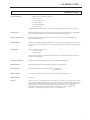
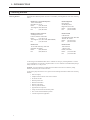
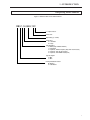
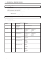

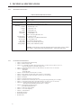
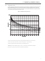
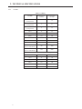
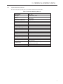
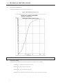
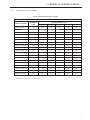
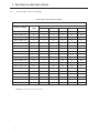
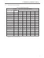
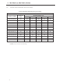
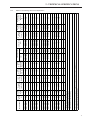
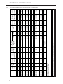
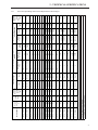
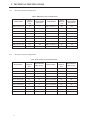
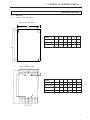
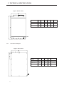
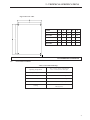

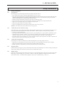
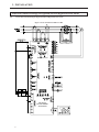
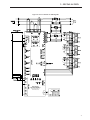
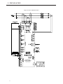
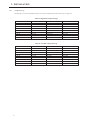
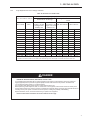
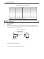
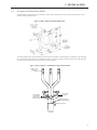
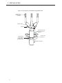
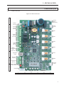
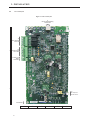
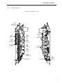

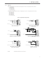
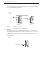
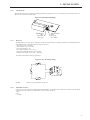
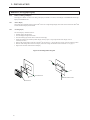
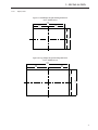
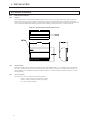
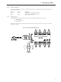
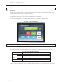
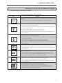
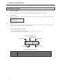
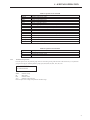
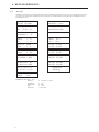
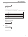
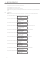
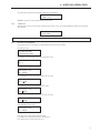
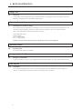

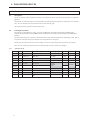
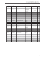
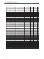
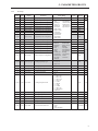
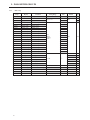
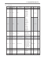
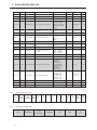
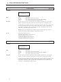
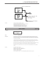
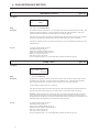
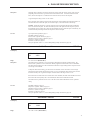
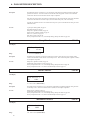
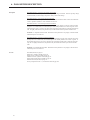
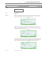
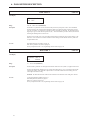
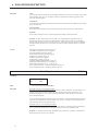
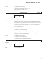
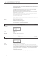
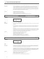
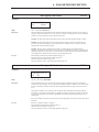
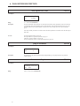
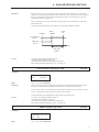
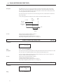
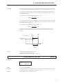
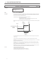
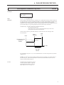
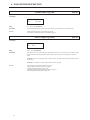
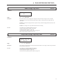
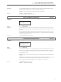
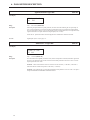
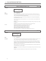
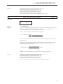
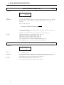
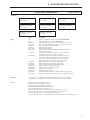
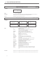
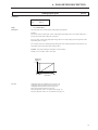
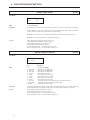
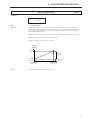
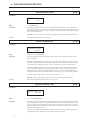
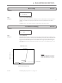
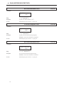
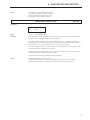
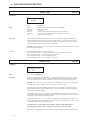
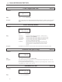
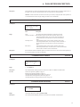
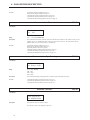
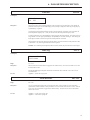
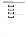
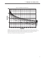
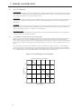
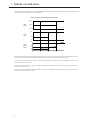
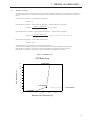
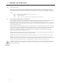
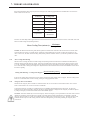
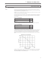
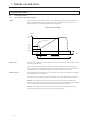
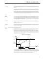
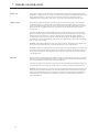
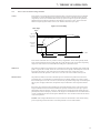
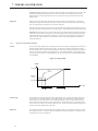
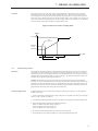

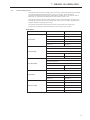
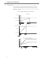
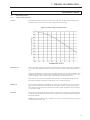
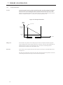
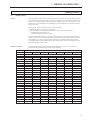
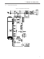
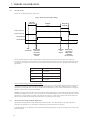
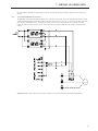
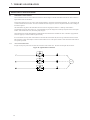
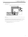
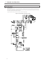
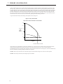
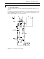
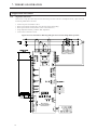
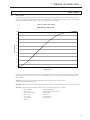
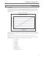
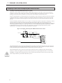
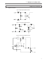
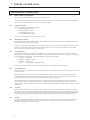
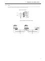

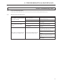
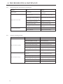
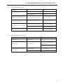
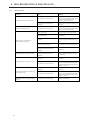
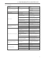
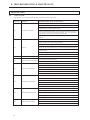
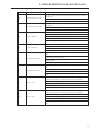
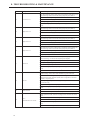
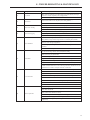
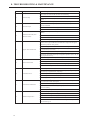
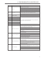
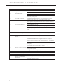
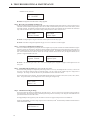
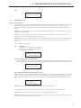
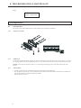
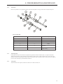


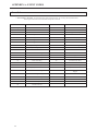
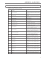
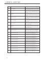
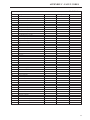
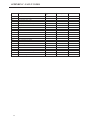
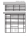
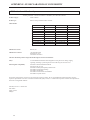
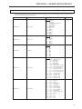
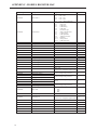
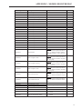
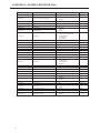
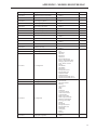
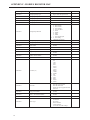
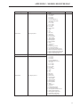
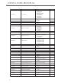
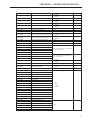
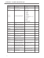
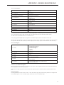
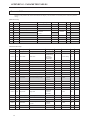
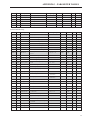
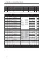
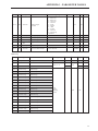
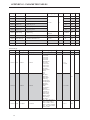
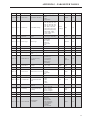
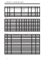
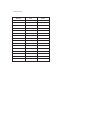


![EX MV MX3 User Manual [May16].vp](http://vs1.manualzilla.com/store/data/005646159_1-0d378a1c318c2dc00419aef6af60da73-150x150.png)

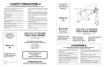

![MX2 sync [final].vp](http://vs1.manualzilla.com/store/data/005975841_1-4533d2555e3004ab9339335fb150c7a8-150x150.png)