1
V:\Technical\ARTWORK\Fitting & Wiring\Word Files HOLDING\442073T (FOR
ISSUE).doc
Sentinel
Kinetic MVHR
and
Kinetic Plus MVHR
Operation & Monitoring
Stock Ref. N°
438222 Kinetic B
438222A Kinetic BS
443319 Kinetic BH
443319A Kinetic S BH
438342 Kinetic V
438342A Kinetic VS
443028 Kinetic Plus B
447938 Kinetic Plus BS
PLEASE RETAIN THESE INSTRUCTIONS WITH THE PRODUCT.
442073T (FOR ISSUE)Copyright © 2009 Vent-Axia Limited. All rights reserved.
About this Document
IMPORTANT
Contents
Product Description
PLEASE READ THESE INSTRUCTIONS
CAREFULLY BEFORE USING THE UNIT.
1. THIS APPLIANCE IS NOT INTENDED FOR USE BY YOUNG
CHILDREN OR INFIRM PERSONS WITHOUT SUPERVISION.
2. YOUNG CHILDREN SHOULD BE SUPERVISED TO ENSURE
THAT THEY DO NOT PLAY WITH THE APPLIANCE.
3. DO NOT ATTEMPT TO REMOVE THE COVERS OF THIS
UNIT. HIGH VOLTAGE IS PRESENT IN THIS UNIT.
Disposal
This product should not be disposed of with
household waste. Please recycle where
facilities exist. Check with your local authority
for recycling advice.
3 Sentinel Kinetic & Sentinel Kinetic Plus ......................................... 3 Control Unit Display ....................................................................... 6 Powering Up the Unit ..................................................................... 8 Startup Screens ............................................................................. 8 Operation and Monitoring
9 Overview ........................................................................................ 9 User Menu Screens ..................................................................... 10 Boost & Purge Screens ................................................................ 12 Status Message Screens ............................................................. 13 Maintenance
15 Caring for the Unit ........................................................................ 15 Filter Maintenance ........................................................................ 15 12 Monthly Maintenance .............................................................. 15 Troubleshooting
16 Diagnosing a Problem .................................................................. 16 Appendix One: Control Mode 02 Description
17 Overview ...................................................................................... 17 Airflow Mode Selection ................................................................. 17 Software Ver 38
Sentinel Kinetic MVHR Operation & Monitoring
2
Product Description
Product Description
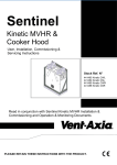
Sentinel Kinetic & Sentinel Kinetic Plus
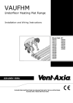
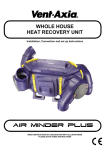
The Vent-Axia Sentinel Kinetic & Sentinel Kinetic Plus Mechanical Ventilation/Heat Recovery (MVHR) is a
heat recovery unit designed for the energy efficient ventilation of houses and similar dwellings, conforming to
the latest requirements of the Building Regulations document F 2010.
The unit is designed for continuous 24 hour exhaust ventilation of stale moist air from bathrooms, toilets and
kitchens. As the stale air is extracted, a heat exchanger within the unit transfers up to 90% of the heat into the
supply air entering the bedrooms and lounge.
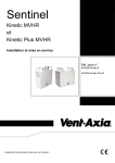
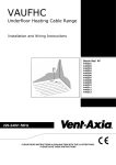
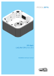
In addition a Kinetic Plus unit is available that maintains a constant air flow independent of change in the system
pressure.
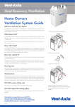
Fig 1: Sentinel Kinetic (Right handed (RH) version shown)
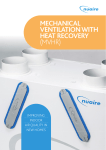
Fig 2: Sentinel Kinetic Plus (Right handed (RH) version shown)
Please check if your unit is RH or LH (Left handed)
Please check if your unit is RH or LH (Left handed)
Sentinel Kinetic MVHR Operation & Monitoring
3
Product Description
Sentinel Kinetic Range Summer By Pass Models.
The Sentinel Kinetic B, BH, Plus B, Plus BS and S BH are fitted with a Summer By Pass (SBP) and will provide
energy-free cooling when the house temperature and ambient temperature allows.
Note that the volume of air provided by this ventilation system is a fraction of that required for space heating or
space cooling and will not in itself be sufficient to cool a room. It will however, provide a contribution and make a
difference.
There are three operating modes, Normal, Evening Purge and Night-time purge.
Normal Mode.
Air flow rate is determined by sensors, boost and timing settings, otherwise is normal rate.
If the room is warmer than the set (shown as "indoor") temperature (i.e. you need the room to be cooler) and the
outdoor air is cooler than the actual room temperature (i.e. the outdoor air could cool your room) then the SBP will
open and the unit will supply cooler air to your room.
Note that the above only applies whilst the outdoor air temperature is above 14 C (adjustable) in order to prevent
cold draughts.
The set ("indoor") temperature should be set 2 or 3 degrees higher than the central heating thermostat and 2 or 3
degrees below any air conditioning thermostat if fitted. This will prevent any clash between the separate systems.
Evening purge Mode.
Intended for use as the outdoor temperature cools in the evening, but reverts to normal control after a set time so
that any increase in noise is avoided overnight.
Air flow rate is always at boost.
The bypass closes and the purge stops if the temperature conditions described in Standard Mode are no longer
met or 5 hours after the bypass opened.
Night-time purge Mode.
Intended for use as the outdoor temperature cools in the evening and continues through the night when cooling is
a higher priority than any increase of noise. Note that the air noise in your system is influenced by the ducting
design and layout and the size and type of vents used in the rooms. If improvements are required speak to your
installer.
Air flow rate is boost.
The bypass closes and the purge stops if the temperature conditions described in Standard Mode are no longer
met.
Sentinel Kinetic MVHR Operation & Monitoring
4
Product Description
Models
438222 - Sentinel Kinetic B with summer bypass.
438222A - Sentinel Kinetic BS with summer bypass.
443319 - Sentinel Kinetic BH with summer bypass and integral humidity sensor.
443319A - Sentinel Kinetic S BH with summer bypass and integral humidity sensor
438342 - Sentinel Kinetic V without summer bypass.
438342A - Sentinel Kinetic VS without summer bypass.
443028 - Sentinel Kinetic Plus B with Summer Bypass and integral humidity sensor.
447938 - Sentinel Kinetic Plus BS with Summer Bypass and integral humidity sensor.
Accessories
441838 - Sentinel Kinetic Plug-in integral humidity sensor
441865 - Wireless enable kit (consists of wireless receiver and one wireless switch).
437827 - Additional wireless switch (up to four may be connected).
441780 - Vent-Wise accessory pack.
442367 - Monza System Cooker Hood 600mm wide.
442368 - Latina System Cooker Hood 900mm wide
443283 - Remote Wired Control.
447340 - Opto coupler
407198 - Pre-Heater Controller
A range of sensors can be used to manage system demand and control the ventilation rate. These include an
internal humidity sensor, humidity sensors for independent mounting in rooms, wireless receiver and wireless
boost switches, CO2 sensor, Ventwise sensors, manual switches and pull cords. For these alternative control
options, see www.vent-axia.com
Sentinel Kinetic MVHR Operation & Monitoring
5
Product Description
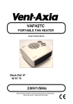
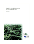
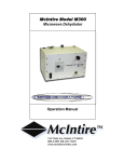
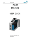
Control Unit Display
The Control Unit is located at the front of the Sentinel Kinetic unit. The Control Unit provides the user interface
for commissioning and monitoring purposes.
Figure 3: Control Unit
Display
The main display is an LCD with automatic backlight,
which is turned off to minimise power consumption
when the unit is operational (see Overview on page 9).
Normal Airflow
30%
Buttons
Four buttons on the Control Unit provide the controls for configuring and monitoring the unit.
Table 1: Control Unit Buttons
Button
Function
Press to adjust settings and press to save settings.
Press to go to the above screen or to increase a parameter value. Press
and hold for more than 2 seconds for fast scrolling.
Press to go to the next screen or to decrease a parameter value. Press and
hold for more than 2 seconds for fast scrolling.
Press to activate Boost mode.
No. of presses
Boost action
(Control Mode 01)
1
Boosts for 30 minutes
2
Boosts for 60 minutes
3
Boosts continuously
4
Back to Normal flow rate
Press and hold for 5 seconds to activate Purge mode. (Press and hold for
5 seconds to cancel Purge).
N.B Additional airflow modes are available from the
button when Control Mode 02 is selected in the
start-up screens see Appendix One for further details.
Sentinel Kinetic MVHR Operation & Monitoring
6
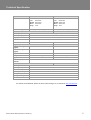
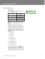
Technical Specification
Performance
Sentinel Kinetic
Airflow
Maximum, FID, 290 m /h
Maximum, FID, 500 m /h
Low
Low
Sound levels (@ 3 m)
Sentinel Kinetic Plus
3
3
default 20%
default 20%
Normal default 30%
Normal default 30%
Boost
default 50%
Boost
default 50%
Purge
100%
Purge
100%
20 dB(A) (normal), 36 dB(A) (boost)
24 dB(A) (normal), 34 dB(A) (boost)
Power
AC Voltage Input
220-240 V AC (single phase)
AC Frequency Input
50 Hz nominal
Supply Fuse
3 A (located in fused spur)
Product Fuse
2 A (located on main PCB)
Rated Power
150 W (max.)
190 W (max.)
Height (excluding
spigots)
550 mm
630 mm
Width (excluding
spigots)
550 mm
775 mm
Depth
285 mm
520 mm
Physical
Weight
Spigot diameter
Condensate pipe
diameter
15 kg
24 kg
125 mm
150 mm
22 mm
Environmental
IP Rating
IP22
Operating Temperature
-20C to +45C
Air Intake Temperature
As above
Operating Humidity
0% to 95% RH
Storage Temperature
-20C to +45C
Storage Humidity
0% to 95% RH
Software Version
V38
For all other technical details, please see the Product Catalogue or our website at www.vent-axia.com.
Sentinel Kinetic MVHR Operation & Monitoring
7
Starting Up
Powering Up the Unit
Switching On
(The unit is designed to run continuously)
To switch the unit on:
1.
Switch on the power at the mains supply isolator feeding the unit.
2.
Following switch-on, the fan motors will start and the Control Unit will display a series of startup screens,
described below.
Switching Off
To switch the unit off: at the unit’s local isolator, turn the power off.
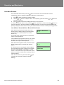
Startup Screens
Sentinel Kinetic Version Screen
The Sentinel Kinetic Version screen displays the
firmware version number for 3 seconds.
V--
No adjustments are possible on this screen.
Language Screen
The Language screen displays the language used for
the screens. It is typically displayed for 5 seconds, or
longer if changing the setting.
Language
English
Control Mode Screen
Selects between Control Mode 01 operation described
herein and the alternative Control Mode 02 described
in Appendix One.
Control Mode
01
Airflow Units Screen
The Airflow Units is a percentage of the unit’s
maximum flow.
Airflow Units
%
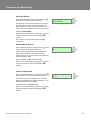
Wireless Control Screen
The Wireless Control screen automatically displays
whether the wireless boost control switch is fitted. It is
typically displayed for 3 seconds.
Wireless Control
Not Fitted
Humidity Sensor Screen
The Humidity Sensor screen displays whether the
humidity sensor is fitted. It is typically displayed for
3 seconds.
Sentinel Kinetic MVHR Operation & Monitoring
Humidity Sensor
Not Fitted
8
Operation and Monitoring
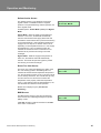
Operation and Monitoring
Overview
When the Sentinel Kinetic unit has been installed and commissioned it should require no further intervention in order to operate,
unless external switches are used to control on/off/boost, etc, or BMS control requires user action.
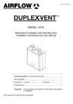
Start-up Screens
V-Language
English
Control Mode
01
Airflow Units
%
Press for Boost
Boost Airflow
50%
Purge
100 %
120 m
Status
Wireless Control
Not Fitted
Dryout Mode
168 h
Humidity Sensor
Not Fitted
Defrost Active
Airflow Mode
Room Too Cold
Fan Off
User Menu
Normal Airflow
30%
BMS
Fan Off
CVP Control
Switched Off
Press for > 5 s
Set Clock
Mon 12:30
Low Airflow
20%
Low Speed – If timer selected
on installation.
Cooker Hood
100 %
Summer Mode
On
Indoor Temp
25 C
Outdoor Temp
14 C
Timeout after 2 m
Sentinel Kinetic MVHR Operation & Monitoring
9
Operation and Monitoring
User Menu Screens
From the Normal Airflow screen, press the
button to access the rest of the User Menu screens.
Changing the value of a setting (if adjustable) is typically a 3-step procedure:
1.
Press
2.
Use the
or
buttons to adjust the value. To scroll quickly, press and hold the
more than 2 seconds.
3.
Press
to select the setting (the setting will flash).
or
buttons for
again to enter the new settings and move to the next screen.
button repeatedly or press and hold the
button for 5
To return to the Normal Airflow screen, press the
seconds. Alternatively, the Normal Airflow screen will be restored if no buttons are pressed for two minutes
(timeout). Settings are stored in a the memory and will be retained in the event of mains power supply failure.
Low Airflow / Normal Airflow / Boost Airflow Screen
When the start-up screens are finished, the Low or
Normal screen is displayed showing operating status
(Low Airflow X % or Normal Airflow X % or Boost
Airflow X %).
Normal Airflow
30 %
The Normal screen displays the rate of normal airflow
(supply air) through the unit.
If the installation has proportional sensors or an internal
humidity sensor fitted, and any of these are boosting
the airflow, an α symbol will be displayed.
When the summer bypass is active, the normal screen
top line will alternate (for 3 seconds) with Summer
Bypass.
SUMMER BYPASS ON
30 %
An interval can be set, see page 38 of the Installation
and Commissioning manual, at which the unit reminds
the user to check the filters. This will be 6, 12 or 18
months. The normal screen top line will include Check
Filter as a reminder to check and, if necessary, clean or
replace the filters.
Filter Service
Suburban
When this has been done, press and hold the
and
buttons for 5 seconds to reset the automatic
message.
Sentinel Kinetic MVHR Operation & Monitoring
10
Operation and Monitoring
Set Clock Screen
From the Normal Airflow screen, simply press the
button once to access the Set Clock screen.
Set Clock
Mon 12:30
The Set Clock Control screen enables you to change
the clock settings. The clock retains its settings for
approximately two weeks without mains power, after
which it will need resetting when power is reconnected
Values are DDD HH:MM.
Return to the normal display by pressing the
button
or leave to timeout and return automatically after 2
minutes.
The unit will not automatically switch for Daylight
saving time.
Summer Mode Screen
From the Set Clock screen, simply press the
twice to access the Summer Mode screen.
button
Summer Mode
On
If the unit is a summer bypass model, the Summer
Mode screen enables you to switch the summer
bypass control on or off. This screen is only displayed
when the bypass is fitted.
Options available are On (default) and Off.
Return to the normal display by pressing the
button
or leave to timeout and return automatically after 2
minutes.
Indoor Temp Screen
From the Summer Mode screen, simply press the
button 3 times to access the Indoor Temp screen.
Indoor Temp
25 C
The Indoor Temp screen enables you to choose the
target room temperature in degrees Centigrade – only
displayed when the bypass is fitted.
Selectable range is 16-40 (25 default).
Return to the normal display by pressing the
button
or leave to timeout and return automatically after 2
minutes.
Sentinel Kinetic MVHR Operation & Monitoring
11
Operation and Monitoring
Boost & Purge Screens
Boost Screen
Pressing the
button activates boost airflow mode
when extra ventilation is required.
No. of presses
Boost action
(Control Mode 01)
1
Boosts for 30 minutes
2
Boosts for 60 minutes
3
Boosts continuously
4
Back to Normal flow rate
Boost Airflow
50 %
N.B Additional airflow modes are available from the
button when Control Mode 02 is selected in the
start-up screens see Appendix One for further
details.
If the wireless boost option is fitted, this can be
triggered from the wireless transmitter/boost switch.
If the installation has switch sensors, is wired to the
lighting, has Vent-Wise sensors or if the internal time
switch is set for periodic operation, operation will
change from normal to boost automatically. Pressing
the
button will reveal a code to show which device
has activated boost.
s1 = Switch S/W1
s2 = Switch S/W2
s3 = Switch S/W3
s4 = Switch SW4
s5 = Switch SW5
v1 = Vent-Wise Input S/W1
v2 = Vent-Wise Input S/W2
v3 = Vent-Wise Input S/W3
ls = Switched live (LS)
w1-4 = Wireless controller
c1-3 = Internal Time switch
button, a
If running on boost due to pressing the
device will ‘take over’ the boost. Flow will return to low /
normal when that device switches off. If a number of
different devices are calling for boost flow, the unit will
run at boost until the last one has reverted to normal.
Sentinel Kinetic MVHR Operation & Monitoring
12
Operation and Monitoring
Purge Screen
Pressing and holding the
button for 5 seconds
activates purge mode when you want to purge air from
the building. The unit will revert to normal flow by
pressing and holding the
button again for 5
seconds. If the wireless boost option is fitted, this can
be triggered from the wireless transmitter/boost switch.
Purge
100 %
120m
Purge mode runs the fans at full speed for 2 hours (120
minutes). The Purge screen displays a countdown of
the time remaining.
Cooker Hood Boost Screen
There is a separate connection for a cooker hood
control which allows the boost level to be higher when
triggered by a Cooker Hood.
Cooker Hood
100 %
Low Airflow Screen
Low Airflow mode is activated when the Normal Airflow
is set to Off, (see page 31 in the Installation and
Commissioning manual for set up details).
Low Airflow
20 %
The Normal Airflow mode can be set to run during the
daytime i.e. from 6am to 11pm, the Low Airflow mode
will then run during the night from 11pm to 6pm.
Status Message Screens
The status message screens override the Normal Airflow and other user screens, and display status and key
operational conditions (temperatures or pressures, etc.) according to how the unit has been configured. If there
is more than one status item to be displayed, the highest priority message is shown.
These screens are displayed in a loop during normal operation of the unit, either after displaying the start-up
screens, or when commissioning has been completed. After a few seconds the display backlight is turned off in
order to minimise power consumption. The
and
buttons can be used to stop the loop sequence in order
to display individual screens for a longer period with the backlight turned on, if required.
Dryout Mode Screen
The Dryout Mode screen displays the time remaining
for the building to dry out. The unit runs at maximum
flow for 1 week.
Sentinel Kinetic MVHR Operation & Monitoring
Dryout Mode
168 h
13
Operation and Monitoring
Defrost Active Screen
The Antifrost screen is only displayed if a summer
bypass is fitted. In installations where a negative
pressure is not permitted during antifrost operation, set
this to bypass mode.
Defrost Active
Airflow Mode
Available options: Airflow Mode (default) and Bypass
Mode.
Airflow Mode - When the supply air temperature is
between 0° and -20°C, antifrost will automatically
activate. This will reduce the supply airflow rate and
increase the extract airflow rate to prevent frost forming
on the heat exchanger. During antifrost operation the
supply motor can stop for 15 minutes and run for 45,
depending on the temperature below 0°C. If the supply
air temperature is -20°C or below the supply fan
switches off and the extract fan continues to run at
reduced rate to prevent frost forming on the heat
exchanger.
Bypass Mode - While the supply air temperature is
below 0°C, the antifrost mode will automatically
activate. This mode will open the bypass to prevent
frost forming on the heat exchanger.
Room Too Cold Screen
The Room Too Cold screen displays the status of the
fan. If the heating system in the building fails or is
switched off and the internal temperature drops below
5°C, the unit will stop running so as to not bring cold air
into an already cold house. The unit will start up every
hour and will run for a short time to measure the
temperature of the property. When the temperature
rises, e.g. the heating system is switched back on, the
unit will restart and continue normal operation.
Room Too Cold
Fan Off
Bottom line of display may be ( Fan Off, Fan
Restarting).
BMS Screen
The BMS screen shows if a Fan Off command has
been received from a Building Management System
(BMS), if used.
BMS Mode
Fan Off
A Fan Off command could be received from the BMS
in the event of a fire alarm.
Sentinel Kinetic MVHR Operation & Monitoring
14
Maintenance
Maintenance
Caring for the Unit
Heat recovery units, by their very nature, require regular maintenance. The Sentinel Kinetic has been designed
to facilitate access to enable maintenance to be carried out easily.
Filter Maintenance
Item
Action
Fan Filters
When the unit displays “Check filters”. This is a reminder to ensure that the filters are not so
dirty that they are blocking the airflow or allowing dirt to pass through. The rate at which the
filters become dirty will vary hugely depending on the environment and the activity within the
property.
1. Open the filter flaps and remove the 2 filters.
2. Clean gently by tapping or carefully using a vacuum cleaner if necessary.
3. Replace the filters
4. Close the filter flaps.
5. Reset the automatic message, press and hold the
and
buttons for 5 seconds.
12 Monthly Maintenance
Item
Action
Fan Filters
(Interval to suit
environment)
Change the Fan Filters depending on which environment the unit has been installed; urban,
suburban or rural.
1. Open the filter flaps and remove the 2 filters.
2. Insert the replacement filters.
3. Close the filter flaps.
4. Reset the automatic message, press and hold the
Unit & Heat Exchanger
Cell
and
buttons for 5 seconds.
Inspect and clean the unit
1. Isolate the mains power supply.
2. Remove front cover from the unit.
3. Remove the 2 filters.
4. Slide out the heat exchanger. For Sentinel Kinetic Plus CVP refer to pages 15 and 16.
5. Wash the outer cover and heat exchanger in warm water using a mild detergent (such as
Milton Fluid) and dry thoroughly.
NOTE: Keep water away from all electrical components and wiring within the unit.
Motors
Inspect the motors for build-up of dust and dirt on the impeller blades, which could cause
imbalance and increased noise levels. Vacuum or clean if necessary.
Condensate Drain
Check the condensate drain tube is secure and clear of debris. Clean if necessary.
Fastenings
Check that all unit and wall-mount fastenings are sufficiently tight and have not become
loose. Re-tighten if necessary.
Sentinel Kinetic MVHR Operation & Monitoring
15
Troubleshooting
Troubleshooting
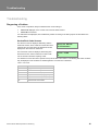
Diagnosing a Problem
In the event of a problem, always troubleshoot the unit according to:
Fault code displayed on the Control Unit or Remote Wired Control.
Fault LED if connected.
If no indications are displayed, then troubleshoot problem according to the fault symptom as described in the
following tables.
Service/Fault Code Screens
The Service screen is displayed, alternating with the
Fault Code screen, when a fault has caused the unit to
switch off and you must phone the telephone number
displayed on the screen for assistance.
Service Phone
01293nnnnnn
The Fault Code screen is displayed, alternating with
the Service screen, when a fault has occurred. Take
note of the fault code when reporting a fault.
Fault Code
01
For assistance contact the service provider and quote the fault code number. The following fault codes numbers
may be displayed. Code numbers are added together if more than one is detected.
Table 2: Fault Codes
Code
Problem
01
Supply Fan not running
02
Extract Fan not running
04
Control PCB 24 V fuse (FS1) failure
08
Temperature sensor T1 (supply) faulty
16
Temperature sensor T2 (extract) faulty
32
Wired Remote Control failure
Sentinel Kinetic MVHR Operation & Monitoring
16
Appendix One
Appendix One: Control Mode 02 Description
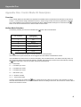
Overview
The functional differences described in this Appendix are available when Control Mode 02 is selected from the start-up
screens. Control Mode 02 assigns alternative functions to certain wiring Terminal Connections (described in Appendix
One of the Installation and Commissioning Manual) and allows additional airflow settings to be accessed via the
button on the front of the Kinetic unit or remote control as shown below:
Airflow Mode Selection
The following switching Functions are available via the
Press
No. of presses
Airflow Mode
(Control Mode 02)
1
Low
2
Normal
3
Boosts 30 minutes
4
Boosts 60 minutes
5
Boosts continuously
6
Cancel
button with Control Mode 02:
10 seconds after last press to cancel and return to normal operation.
If the wireless boost option is fitted, this can be triggered from the wireless transmitter/boost switch.
If the installation has switch sensors, is wired to the lighting, has Vent-Wise sensors, Vent-Wise momentary switch or if
the internal time switch is set for periodic operation, operation will change from normal to boost automatically. Pressing
the
button will reveal a code to show which device has activated boost.
s4 = Switch SW4
v1 = Vent-Wise Input S/W1
v2 = Vent-Wise Input S/W2
v3 = Vent-Wise Input S/W3
ls = Switched live (LS)
w1-4 = Wireless controller
c1-3 = Internal Time switch
If running on boost due to pressing the
button, another device may ‘take over’ the boost. Flow will return to normal
when that device switches off. If a number of different devices are calling for boost flow, the unit will run at boost until the
last one has reverted to normal.
17
Appendix One
The
Guarantee
Applicable only to products installed and used in the United Kingdom. For details of guarantee outside the United Kingdom contact your local supplier.
Vent-Axia guarantees its products for two years from date of purchase against faulty material or workmanship. In the event of any part being found to be
defective, the product will be repaired, or at the Company’s option replaced, without charge, provided that the product:-
Has been installed and used in accordance with the instructions given with each unit.
Has not been connected to an unsuitable electricity supply. (The correct electricity supply voltage is shown on the product rating label
attached to the unit).
Has not been subjected to misuse, neglect or damage.
Has not been modified or repaired by any person not authorised by the company.
IF CLAIMING UNDER TERMS OF GUARANTEE
Please return the complete product, carriage paid to your original supplier or nearest Vent-Axia Centre, by post or personal visit. Please ensure that it is
adequately packed and accompanied by a letter clearly marked “Guarantee Claim” stating the nature of the fault and providing evidence of date and
source of purchase.
Head Office: Fleming Way, Crawley, West Sussex, RH10 9YX.
UK NATIONAL CALL CENTRE, Newton Road, Crawley, West Sussex, RH10 9JA
SALES ENQUIRIES:
Tel: 0344 8560590
Fax: 01293 565169
TECHNICAL SUPPORT
Tel: 0344 8560594
Fax: 01293 532814
For details of the warranty and returns procedure please refer to www.vent-axia or write to Vent-Axia Ltd, Fleming Way, Crawley, RH10 9YX
442073T
© 2013 Vent-Axia Limited. All rights reserved.
0315