1
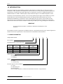
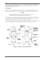
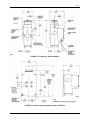
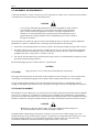
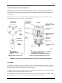
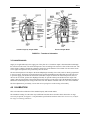
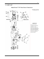
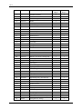
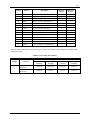
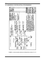
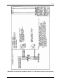
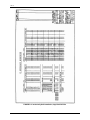
INSTALLATION AND SERVICE INSTRUCTION
SD771
Rev 7
February 2006
Supersedes Issue 6
Model Series 771
I/P Valve Service Transducers
SD771
TABLE OF CONTENTS
SECTION AND TITLE
PAGE
PREFACE ....................................................................................................................................................................3
1.0 INTRODUCTION .................................................................................................................................................6
1.1 MODEL DESIGNATION...................................................................................................................................6
1.2 SPECIFICATIONS .............................................................................................................................................7
1.2.1 CSA Hazardous Locations............................................................................................................................8
1.3 PRODUCT SUPPORT ........................................................................................................................................9
2.0 INSTALLATION ................................................................................................................................................11
2.1 MOUNTING .....................................................................................................................................................12
2.2 INSTRUMENT AIR REQUIREMENTS..........................................................................................................14
2.3 PIPING ..............................................................................................................................................................14
2.4 EXHAUST ALIGNMENT................................................................................................................................14
2.5 SHIPPING AND RESTRICTION SCREWS....................................................................................................15
2.6 WIRING ............................................................................................................................................................15
2.6.1 Intrinsically Safe Models............................................................................................................................16
3.0 OPERATION.......................................................................................................................................................16
3.1 STANDARD CAPACITY MODEL .................................................................................................................16
3.2 BOOSTED MODEL .........................................................................................................................................17
4.0 CALIBRATION ..................................................................................................................................................17
4.1 TEST EQUIPMENT .........................................................................................................................................18
4.2 PROCEDURE ...................................................................................................................................................18
5.0 MAINTENANCE ................................................................................................................................................19
5.1 PREVENTIVE ..................................................................................................................................................19
5.2 CLEANING STANDARD CAPACITY MODELS..........................................................................................19
5.2.1 Filter Screens ..............................................................................................................................................19
5.2.2 Restriction Screw, Nozzle, and Nozzle Seat...............................................................................................19
5.3 CLEANING BOOSTED MODELS..................................................................................................................20
5.3.1 Pilot Base....................................................................................................................................................20
5.3.2 Exhaust Ring ..............................................................................................................................................20
5.3.3 Nozzle Housing ..........................................................................................................................................20
5.4 TROUBLSHOOTING.......................................................................................................................................21
5.5 COIL ASSEMBLY REPLACEMENT..............................................................................................................22
5.6 FLOAT REPLACEMENT ................................................................................................................................23
6.0 WARRANTY .......................................................................................................................................................24
7.0 PARTS LIST........................................................................................................................................................25
8.0 HAZARDOUS LOCATION INSTALLATION DRAWINGS ........................................................................28
2
SD771
LIST OF ILLUSTRATIONS
FIGURE AND TITLE
2-1
2-2
2-3
2-4
3-1
4-1
5-1
8-1
8-2
8-3
8-4
PAGE
Installation, Standard Capacity Models................................................................................................................12
Installation, Boosted Models................................................................................................................................13
Optional Mounting Adapter Plate, All Models ....................................................................................................13
Restriction Screw and Exhaust Port Locations and Electrical Connections ........................................................15
Transducer Schematics.........................................................................................................................................17
Housings...............................................................................................................................................................18
Coil Alignment.....................................................................................................................................................23
Intrinsically Safe Installation with Safety Barriers, Model 77 or 771..................................................................28
Intrinsically Safe Installation, Model 77 or 771 & Foxboro Spec 200 or Interspec Nest ....................................29
Intrinsically Safe Installation, Approved Barriers................................................................................................30
Intrinsically Safe Connection Diagram, Model 77 and 771, Entity Parameters...................................................31
Changes for Revision 7, February 2006
Significant changes for this revision are indicated by change bars in the outside page margins. Some of these
changes are listed below.
SECTION
CHANGE
Cover
Changed publication revision number and date.
1.2 Specifications
Added supply pressure specifications for 3-27 psig output models.
1.3 Product Support
Updated.
All product designations may be trademarks or product names of Siemens Energy & Automation, Inc. or other supplier
companies whose use by third parties for their own purposes could violate the rights of the owners.
Siemens Energy & Automation, Inc. assumes no liability for errors or omissions in this document or for the application and use of information
included in this document. The information herein is subject to change without notice.
Procedures in this document have been reviewed for compliance with applicable approval agency requirements and are considered sound
practice. Neither Siemens Energy & Automation, Inc. nor these agencies are responsible for repairs made by the user
3
SD771
PREFACE
Conventions and Symbols
The following symbols may appear in this manual and may be applied to the equipment. The reader should become
familiar with the symbols and their meaning. Symbols are provided to quickly alert the user to safety related
situations, issues, and text.
Symbol
DANGER
Meaning
Indicates an immediate hazardous situation which, if not avoided, will result in death
or serious injury.
WARNING
Indicates a potentially hazardous situation which, if not avoided, could result in death
or serious injury.
CAUTION
Indicates a potentially hazardous situation which, if not avoided, may result in minor
or moderate injury.
CAUTION
NOTICE
Important
Note
Indicates a potentially hazardous situation which, if not avoided, may result in
property damage.
Indicates a potential situation which, if not avoided, may result in an undesirable
result or state.
Identifies an action that should be taken to avoid an undesirable result or state.
Identifies additional information that should be read.
Electrical shock hazard. The included Warning text states that the danger of
electrical shock is present.
Electrical shock hazard. Indicated that the danger of electrical shock is present.
Explosion hazard. Indicates that the danger of an explosion hazard exists.
Electrostatic discharge. The presence of this symbol indicates that electrostatic
discharge can damage the electronic assembly.
Conventions and Usage Notes:
•
Part numbers are for items ordered from the Process Industries Division of Siemens Energy & Automation,
except as noted.
Qualified Persons
The described equipment should be installed, configured, operated, and serviced only by qualified persons
thoroughly familiar with this publication. A copy of this publication is shipped with the equipment. The current
version, in Portable Document Format (PDF), is available at http://www.sea.siemens.com/ai/.
4
SD771
For the purpose of this publication and product labels, a qualified person is one who is familiar with the installation,
construction, and operation of the equipment, and the involved hazardous. In addition, he or she has the following
qualifications:
•
Is trained and authorized to energize, de-energize, clear, ground and tag circuits and equipment in accordance
with established safety practices.
•
Is trained in the proper care and use of protective equipment such as rubber gloves, hard hat, safety glasses or
face shields, flash clothing, etc., in accordance with established safety practices.
•
Is trained in rendering first aid.
Scope
This publication does not purport to cover all details or variations in equipment, nor to provide for every possible
contingency to be met in connection with installation, operation, or maintenance. Should further information be
desired or should particular problems arise which are not covered sufficiently for the purchaser’s purposes, the
matter should be referred to one of the support groups listed in the Product Support section of this manual.
The contents of this manual shall not become part of or modify any prior or existing agreement, commitment or
relationship. The sales contract contains the entire obligation of Siemens. The warranty contained in the contract
between the parties is the sole warranty of Siemens. Any statements continued herein do not create new warranties
or modify the existing warranty.
General Warnings and Cautions
WARNING
This equipment contains hazardous voltages, and it has been certified for use in the hazardous locations specified on
the product nameplate and in the Model Designation and Specifications section. Death, serious personal injury, or
property damage can result if safety instructions are not followed. Only qualified personnel should work on or
around this equipment after becoming thoroughly familiar with all warning, safety notices, and maintenance
procedures contained herein. The successful and safe operation of this equipment is dependent upon proper
handling, installation, operation, and maintenance.
The perfect and safe operation of the equipment is conditional upon proper transport, proper storage, installation
and assembly, as well as, on careful operation and commissioning.
The equipment may be used only for the purposes specified in this publication.
CAUTION
Electrostatic discharge can damage or cause the failure of semiconductor devices such as integrated
circuits and transistors. The symbol at right may appear on a circuit board or other electronic assembly
to indicate that special handling precautions are needed.
•
A properly grounded conductive wrist strap must be worn whenever an electronics module or circuit board is
handled or touched. A service kit with a wrist strap and static dissipative mat is available from most electronic
supply companies.
•
Electronic assemblies must be stored in anti-static protective bags when not installed in equipment.
5
SD771
1.0 INTRODUCTION
This instruction describes the installation, operation, and maintenance of Model Series 771 I/P Valve Service
Transducers. 1 These transducers are intended to be used for valve service. They provide a pneumatic output that is
proportional to a mAdc input. Input and output ranges are stated below in Section 1.1 Model Designation. Two
standard models are available: standard capacity output and boosted output; see the Model Designation section.
Transducers with a model number suffix F1 or F2 are Factory Mutual System approved for installation in various
National Electrical Code classified hazardous locations. Note that particular attention must be given to the
installation and maintenance of transducers whose model numbers have the suffix F1. These models are FM
approved to be part of an intrinsically safe system when installed and maintained according to the requirements
outlined in this instruction and in the installation instructions provided by the energy limiting barrier manufacturer.
IMPORTANT
Save this Instruction and make it available for installation and maintenance of the
transducer.
The transducers meet the requirements of a NEMA4 enclosure. Consideration must be given to exhaust alignment to
maintain the enclosure requirements as stated in the Section 2 Installation of this instruction.
1.1 MODEL DESIGNATION
Sample Model Number
771
16
S
N
I/P Transducer
Input/Output Range (see the table below)
Model No.
Entry
3
8
16
40
Input Range
(mAdc)
1-5
4-20
4-20
10-50
Output Range
(psig)
3-15
3-27
3-15
3-15
Input Impedance
(Ohms)
2450
610
185
30
Output Capacity
B = Boosted
S = Standard
Options
N = None
T = Terminal Strip
Electrical Approval (Factory Mutual
N = None
F1 Intrinsically Safe
F2 Non-Incendive
Note: For approval details, see Electrical Classification in Section 1.2 Specifications
1
6
May be manufactured by either Siemens or Moore Products Co.
F1
SD771
1.2 SPECIFICATIONS
Supply Pressure
3-15 psig Output Models
Normal...........................................................20 psig
Minimum.......................................................18 psig
Maximum
Standard Capacity Models .....................30 psig
Boosted Models......................................50 psig
3-27 psig Output Models
Normal...........................................................30 psig
Maximum ......................................................35 psig
Effect
Standard Capacity Models ............................20:1
Boosted Models.............................................40:1
Output Capacity
Standard Capacity Models....................................0.16 SCFM @ 20 psig supply
Boosted Models....................................................2.0 SCFM @ 20 psig supply
Maximum Air Consumption
Standard Capacity Models....................................Less than 0.25 SCFM @ 20 psig supply
Boosted Models....................................................0.2 SCFM @ 20 psig supply
Ambient Temperature Limits ......................................-40°C (-40°F) to +80°C (+176°F)
Pneumatic Connections
Standard Capacity Models....................................1/4 NPT
Boosted Models....................................................1/8 NPT
Independent Linearity
Standard Capacity Models....................................Less than 0.5% of span
Boosted Models....................................................Less than 1% of span
Hysteresis
Standard Capacity Models....................................Less than 0.1% of span
Boosted Models....................................................Less than 0.25% of span
Repeatability................................................................Better than 0.02 psi
Dead Spot ....................................................................Less than 0.05% of span
Response Level............................................................<0.025% of span
Electrical Classification
F1 Model Number Suffix .....................................Intrinsically safe for Class I, II, III Division 1 Groups A, B, C,
D, F, & G when installed in accordance with Siemens drawing
15032-7704 or 15032-7705.
F2 Model Number Suffix .....................................N on-incendive for Class I, Division 2, Groups A, B, C, & D.
Dust ignition proof for Class II, Division 1, Groups E, F & G.
Suitable for Class III, Division 1 and NEMA 4.
CE Marked ..................................................................EMC Directive 89/336/EC; EN50081-1, EN50081-2,
EN61000-6-1, EN61000-6-2
Pressure Equipment Directive .....................................Designed and manufactured in accordance with Article 3,
Paragraph 3 of Directive 97/23/EC
7
SD771
1.2.1 CSA Hazardous Locations
This section provides CSA hazardous location precautions that should be observed by the user when installing or
servicing the equipment described in this manual. These statements supplement those given in the preceding section.
WARNING
Explosion can cause death or serious injury.
Failure to observe the following precautions could result in an
explosion hazard.
Installation in hazardous locations must be in
accordance with the Canadian Electrical Code, as
required by local regulations.
Precautions - English
For Class I, Division 1 and Class I, Division 2 hazardous locations:
• Use only factory-authorized replacement parts. Substitution of components can impair the suitability of this
equipment for hazardous locations.
For Division 2 hazardous locations:
When the equipment described in this Instruction in installed without safety barriers, the following precautions
should be observed. Switch off electrical power at its source (in non-hazardous location) before connecting or
disconnecting power, signal, or other wiring.
Précautions - Français
Emplacements dangereux de classe I, division 1 et classe I, division 2:
• Les pièces de rechange doivent être autorisées par l’usine. Les substitutions peuvent rendre cet appareil
impropre à l’utilisation dans les emplacements dangereux.
Emplacement dangereux de division 2:
Lorsque l’appareil décrit dans la notice ci-jointe est installé sans barrières de sécurité, on doit couper l’alimentation
électrique a la source (hors de l’emplacement dangereux) avant d’effectuer les opérations suivantes branchment ou
débranchement d’un circuit de puissance, de signalisation ou autre.
8
SD771
1.3 PRODUCT SUPPORT
This section provides the Internet site addresses, e-mail addresses, telephone
numbers, and related information for customers to access Siemens product support.
When contacting Siemens for support:
•
•
Please have complete product information at hand:
•
For hardware, this information is provided on the product nameplate
(part number or model number, serial number, and/or version).
•
For most software, this information is given in the Help > About screen.
If there is a problem with product operation:
•
Is the problem intermittent or repeatable? What symptoms have been observed?
•
What steps, configuration changes, loop modifications, etc. were performed before the problem
occurred?
•
What status messages, error messages, or LED indications are displayed?
•
What troubleshooting steps have been performed?
•
Is the installation environment (e.g. temperature, humidity) within the product’s specified operating
parameters? For software, does the PC meet or exceed the minimum requirements (e.g. processor,
memory, operating system)?
•
A copy of the product Service Instruction, User’s Manual, or other technical literature should be at hand. The
Siemens public Internet site (see the table) has current revisions of technical literature, in Portable Document
Format, for downloading.
•
To send an instrument to Siemens for repair, request a Return Material Authorization (RMA).
IMPORTANT
An instrument must be thoroughly cleaned (decontaminated) to remove any process materials,
hazardous materials, or blood born pathogens prior to return for repair. Read and complete the
Siemens RMA form(s).
TABLE 1.1 Contact Information
Telephone
United States
of America
Fax
E-mail
Hours of Operation
Public Internet Site
Repair Service
+1 800 569 2132, option 2 for Siemens and Moore brand
instruments
+1 215 283 6358
[email protected]
8 a.m. to 4:45 p.m. eastern time
Monday – Friday (except holidays)
http://www.sea.siemens.com/ia
+1 215 646 7400 extension 3187
For contact information outside the U.S.A., visit the Siemens public Internet site (see the above table for the URL),
locate “Customer Support Process Instrumentation,” and click on the Contact Tech Support link to access the
Global Support link.
The current revision of this publication and other Siemens technical publications can be found at the Siemens public
Internet site. The publications are in Portable Document Format (PDF).
9
SD771
10
SD771
2.0 INSTALLATION
This section describes transducer installation in hazardous and non-hazardous locations. Each Transducer nameplate
shows the hazardous location classifications for which that transducer has been Factory Mutual System approved
and/or Canadian Standards Association certified.
All transducer installations should be in accordance with either the current edition of the National Electrical Code
(NEC) or the Canadian Electrical Code (CEC), as required by local regulations.
WARNING
Explosion can cause death or serious injury.
Failure to observe the following precautions could result in an
explosion hazard.
Installation in hazardous locations must be in
accordance with either the NEC or the CEC as required
by local regulations.
The F1 (suffix) models must be used in conjunction with energy limiting barriers. See drawing 15032-7704 or
15032-7705 in Section 8. See Section 1.2 Specifications for additional information.
11
SD771
A typical intrinsically safe system consists of one or more F1 (suffix) transducers installed in a hazardous area, the
required quantity of appropriate energy limiting barriers installed in a non-hazardous location, and the needed
length of interconnecting twisted-pair cables.
2.1 MOUNTING
Figures 2-1 and 2-2 show dimensions, mounting hole locations, electrical access, and pneumatic connections.
Mount the transducer in an upright, vertical position. Tilting up to 10° from vertical will not affect its operation
CAUTION
Mounting the transducer where the specified ambient temperature limits may be
exceeded can adversely affect performance and may cause damage.
A flat adapter plate is available for mounting the transducer to a blind wall. The adapter plate comes in a kit (PN
12330-100) with two 1/4-20 flat head screws for mounting the plate to the transducer. Either pair of transducer-toadapter plate mounting holes can be used. See Figure 2-3 for adapter plate dimensions.
A 2" pipe mounting kit (PN 12334-130) is also available. This kit allows the transducer to be mounted on a 2" O.D.
pipe. It consists of a mounting bracket to mount the transducer and a U-bolt assembly for pipe mounting.
FIGURE 2-1 Installation, Standard Capacity Models
12
SD771
FIGURE 2-2 Installation, Boosted Models
FIGURE 2-3 Optional Mounting Adapter Plate, All Models
13
SD771
2.2 INSTRUMENT AIR REQUIREMENTS
Connect the transducer to a source of clean, dry, oil-free instrument air. Failure to do so will increase the possibility
of a malfunction or a deviation from specified performance.
CAUTION
Use of process fluids other than instrument air is not recommended. No claim is made as
to the suitability of this product for use with other process fluids, such as hazardous
gases, except as listed on the appropriate certificate. Non-approved instruments are
suitable for use with instrument air only. Optional features and modifications such as
tapped exhaust do not imply suitability for use with hazardous gases except as listed on
the approval certificate.
The requirements for a quality air supply are stated in the Instrument Society of America's "Quality Standard for
Instrument Air" (ISA-S7.3 or BS5967: Part 2). Basically, this standard calls for the following.
•
Particle Size: The maximum particle size in the air stream at the instrument should be no larger than 3 microns.
•
Dew Point: The dew point - at line pressure - should be at least 10°C (18° F) below the minimum temperature
to which any part of the instrument air system is exposed at any season of the year. Under no circumstances
should the dew point - at line pressure - exceed 2°C (35.5°F).
•
Oil Content: The maximum total oil or hydrocarbon content, exclusive of noncondensibles, should not exceed 1
ppm under normal operating conditions.
Recommended supply pressure is listed in Section 1.2 Specifications.
CAUTION
Supply pressure in excess of the specified maximum may cause damage.
2.3 PIPING
The supply (IN) and output (OUT) connections on the transducer are shown in Figures 2-1 and 2-2. Quarter-inch
O.D. tubing is recommended for piping to the transducer. Before making connections, blow out all piping.
Use pipe sealant sparingly and then only on the male threads of the tube fittings. A non-hardening sealant is
strongly recommended. There must be no leaks, especially in the output. Leak-test all fittings and tube connections.
2.4 EXHAUST ALIGNMENT
The transducer has two exhaust ports: one external, at the front of the top housing, and the other internal, behind the
access cover; see Figure 2-4. As shipped, two sealing screws are installed: one is installed in the external exhaust
port at the front of the top housing, and a second is installed in the condensation drain. This configuration allows the
transducer's exhaust air to purge the terminal enclosure, the conduit, and associated electronic enclosure (if used).
CAUTION
Do not remove either the exhaust sealing screw or the condensation drain sealing screw
in a Class II hazardous location or under any NEMA 4 condition.
If airtight conduit, conduit fittings, and electronic enclosures are used, move the exhaust sealing screw to the
internal exhaust port in the terminal enclosure (Figure 2-4) and remove the condensation drain sealing screw. This
allows the transducer exhaust to vent to atmosphere through the external exhaust port. It also allows any
accumulated condensation from the instrument air supply to drain from the coil cavity.
14
SD771
2.5 SHIPPING AND RESTRICTION SCREWS
A standard capacity model has a factory-installed shipping screw in the center of the top housing to protect the
transducer's nozzle during shipment. The restriction screw (stamped R) is located just behind the shipping screw.
Interchange these two screws before placing the instrument in operation. Turn the restriction screw in tightly for
proper operation.
If the transducer is to be moved to another location, return the shipping and restriction screws to their original
positions to protect the nozzle. See Figure 2-4 for the positions.
Shipping and Restriction Screws
Exhaust Alignment and Electrical Connections
FIGURE 2-4 Restriction Screw and Exhaust Port Locations and Electrical Connections
2.6 WIRING
A transducer is provided with two 18", 18 AWG (0.96 mm2) wires that exit the enclosure. Optionally, these wires
are terminated at a terminal strip within the enclosure. Figures 2-1, 2-2, and 2-4 locate the access cover and the 1/2"
conduit connection. Route all wiring through the conduit connection.
As shipped from the factory, the conduit connection is a vent path for the transducer's exhaust. Refer to the Section
2.4 Exhaust Alignment if airtight conduit or fittings are used.
The recommended wire size is 22 AWG (0.38 mm2) stranded or solid. Use insulated, crimp-on ring tongue or spring
spade tongue terminals for #6 screws. Use of a high quality crimping tool is recommended.
15
SD771
No special considerations are required for wiring a non-intrinsically safe transducer. However, intrinsically safe
models must be installed as detailed in the next section.
2.6.1 Intrinsically Safe Models
An F1 (suffix) model is considered intrinsically safe only when it has a nameplate with the FM logo and the words
INTRINSICALLY SAFE.
Install the transducer in strict compliance with the instructions furnished by the barrier manufacturer and in
accordance with Siemens drawing 15032-7704 (FM and CSA) or 15032-7705 (FM only). See Section 1.2
Specifications for additional information. See Section 8 for the referenced drawings.
1.
Install the F1 (suffix) model transducer in the hazardous area as detailed by this section of this instruction.
2.
Install the required energy limiting barriers in the non-hazardous area. Refer to the barrier manufacturer's
instructions and to the appropriate connection diagram in this instruction.
3.
Install the required wiring between the F1 (suffix) model transducer and the barriers. Use shielded or
unshielded multi-pair or single-pair cables. Ground the transducer body as required.
4.
In a similar manner, install the required wiring between the barriers and the output terminals of the device
driving the transducer.
5.
Install the redundant ground system for the barrier installation as specified by the barrier manufacturer.
6.
Check all signal and ground connections.
7.
Check all pneumatic connections and transducer adjustments.
8.
Check the calibration of the transducer as outlined in the Section 4 Calibration.
3.0 OPERATION
As shown in Figure 3-1, there are two models: standard capacity output and boosted output. In both models, the
input coil and float are attached to a common center shaft to form the “moving coil assembly”. This assembly is free
to move vertically. The float is submerged in Silicone fluid and is sized so that the resultant buoyant force equals
the weight of the moving coil assembly. This puts the moving coil assembly into a state of neutral buoyancy, which,
together with the viscous damping of the Silicone fluid, makes the transducer insensitive to shock and vibration.
The permanent magnet provides a magnetic field that passes through the input coil. Current flowing through the coil
reacts with the magnetic field to force the moving coil assembly closer to the nozzle. The top end of the common
center shaft serves as a nozzle seat that restricts the flow of air exhausting from the nozzle.
3.1 STANDARD CAPACITY MODEL
Supply air is routed to the nozzle through a restriction. The restriction and the nozzle form a pressure-divide circuit.
The pressure in the nozzle (actually a backpressure) varies according to the restrictive effect imposed by the nozzle
seat. The nozzle backpressure is the output of the transducer.
The nozzle forms a column of air that has a diameter equal to the nozzle diameter. This column of air acts on the
nozzle seat to oppose and equal the force produced by the coil. The force produced by the coil is continuously
balanced by the nozzle backpressure so that the transducer output pressure is, at all times, directly proportional to
the coil current.
The Zero adjustment is provided by a screw that varies a spring force on the moving coil assembly.
16
SD771
Standard Capacity Output Model
Boosted Output Model
FIGURE 3-1 Transducer Schematics
3.2 BOOSTED MODEL
Supply air is applied directly to the supply port of the pilot valve. Transducer output is biased and then fed through
the restriction to the nozzle. The nozzle backpressure varies according to the restrictive effect of the nozzle seat. The
nozzle forms a column of air that has a diameter equal to the nozzle diameter. This column of air acts on the nozzle
seat to oppose and equal the force produced by the coil current.
The nozzle backpressure is the input to the boosted diaphragm assembly (lower side), and it is directly proportional
to the coil current. An increase in nozzle backpressure operates the diaphragm assembly that moves the pilot valve
to open the supply port and increase the booster (transducer) output. A decrease in nozzle backpressure, due to a
decrease in coil current, operates the diaphragm assembly to open the exhaust port and decrease the output. The
output is directly proportional to the nozzle backpressure and it acts on the upper side of the diaphragm assembly to
balance the nozzle backpressure acting on the lower side. Note that the restriction tube serves as a circuit stabilizer.
The Zero adjustment is provided by a screw that varies a spring force on the moving coil assembly.
4.0 CALIBRATION
This section describes calibration of the standard capacity and boosted models.
The transducer housing for some units may be different from that shown elsewhere in this instruction. A range
screw may be present; see Figure 4-1. All performance specifications remain as stated. It is not necessary to adjust
the range screw during calibration.
17
SD771
Standard Housing
Housing with Range Screw
FIGURE 4-1 Housings
4.1 TEST EQUIPMENT
Gather the following equipment to calibrate the transducer. For any instrument, the test equipment used for
calibration should be at least twice as accurate as the specified accuracy of the instrument being calibrated.
1.
0-50 mAdc source
2.
Digital Multimeter: Accuracy to 0.1% of reading
3.
Test Gauge: Range, 0-15 psig (0-30 psig for 3 to 27 psig output); 0.02 psi per division; accurate to 0.6% of full
scale
4.
Supply Air Source: 20 psig
4.2 PROCEDURE
1.
Position the Transducer so that it is upright and within 10 degrees of vertical. If the transducer has been lying
on its side, allow approximately 15 minutes before attempting a final calibration. This allows the transducer's
viscous damping fluid to collect at the bottom of the transducer.
2.
Refer to Figures 2-1, 2-2, and 2-4 and connect the test equipment to the transducer.
1) Connect the test gauge to the Output port.
2) Connect the supply air source to the Supply connection.
3) Connect the current source and digital multimeter to the two signal input wires or optional terminal block.
Observe polarity.
3.
Standard capacity model only – Refer to Section 2.5 and install the restriction screw (stamped R) in its
operating position. An instruction label on the transducer also explains the steps involved.
4.
Set the milliamp source to the starting point value for the input signal range (e.g. 4 mA for a 4 to 20 mA range).
Adjust the transducer's ZERO for a 3 psig output. The ZERO adjustment screw changes the operating level.
Turn the screw clockwise to raise the output pressure.
5.
Exercise the milliamp source from the transducer’s minimum input to maximum input and then to minimum
input (e.g. 4 mA to 20 mA to 4 mA). Transducer output should be 3 psig. If not, repeat step 4 and retest.
18
SD771
5.0 MAINTENANCE
This section provides detailed procedures for cleaning standard capacity and boosted models. Troubleshooting a
transducer is described and procedures are provided for coil assembly and float replacement. All maintenance
procedures require a transducer to be removed from service.
WARNING
Improper service and/or substitution of components may impair the electrical safety of
the instrument.
5.1 PREVENTIVE
Most problems associated with pneumatic instruments can be avoided by the use of clean, dry, oil-free instrument
air. Refer to Section 2.2 Instrument Air Requirements in this manual and to the Instrument Society of America’s
publication “Quality Standard for Instrument Air” (ISA-S7.3).
5.2 CLEANING STANDARD CAPACITY MODELS
The filter screens, restriction screw, nozzle and nozzle seat can be cleaned without dismounting the transducer. All
are located in the top housing; refer to the parts list at the end of this instruction for disassembly and assembly.
Refer to the Parts List as needed for part identification.
5.2.1 Filter Screens
There is a filter screen in the supply (IN) port and in the output (OUT) port.
1.
Remove the transducer from service. Remove supply air from the transducer.
2.
Remove four screws and lockwashers from the top housing. Remove the housing by pulling straight up.
3.
Blow the two screens down in a reverse direction.
1) Remove the restriction screw (turn counterclockwise with a screwdriver).
2) Cover the nozzle opening with a finger. Blow compressed air into the port from which the restriction screw
was removed. If the dirt remains, loosen it mechanically or chemically and repeat the blow down
procedure.
Screen Replacement - If a screen is damaged or cannot be cleaned, it must be replaced.
4.
To clean the restriction screw and the nozzle and nozzle seat, go to Section 5.2.2 below. Otherwise, continue to
step 5.
5.
Install the restriction screw in the top housing.
6.
Install the top housing and secure with the four screws and lockwashers removed earlier.
5.2.2 Restriction Screw, Nozzle, and Nozzle Seat
1.
The restriction is accessible from the tip of the screw. Clean the restriction with a solvent. If the solvent does
not clean the restriction, run a 0.021-inch drill blank through the restriction, from the tip of screw.
2.
Inspect the O-ring on the restriction screw. Replace the O-ring if damaged.
3.
Install the restriction screw in the top housing.
4.
Go to Section 5.2.3.
5.
The nozzle is part of the top housing. The nozzle seat is in the transducer housing; the seat is the top end of the
center shaft. See Figure 3-1. Clean the nozzle and nozzle seat by wiping with a dry cloth or a solvent dampened
19
SD771
cloth. Do not use abrasive cleaning agents. The important parts of the nozzle to clean are its inner diameter
surfaces and the sharp edge of its face.
6.
Install the top housing and secure with the four screws and lockwashers removed above.
5.3 CLEANING BOOSTED MODELS
The items that may require cleaning on a periodic basis are shown in the following table. Refer to the Parts List as
needed for part identification.
Pilot Base
Exhaust Ring
Nozzle Housing
Supply air filter screen
Pilot air filter screen
Restriction screw
Valve plunger
Nozzle
Supply seat
Nozzle seat
Exhaust seat
Restriction tube
5.3.1 Pilot Base
1.
Remove the Transducer from service. Remove supply air.
2.
Remove the retaining nut in the pilot base with a 9/16" wrench.
3.
Remove the valve plunger and supply air filter screen. These should fall out along with the plunger spring.
4.
Clean the valve plunger with a solvent.
5.
Blow compressed air through the supply air filter screen. If this does not dislodge the dirt, loosen it
mechanically or with a solvent and blow down again.
Screen Replacement - If a screen is damaged or cannot be cleaned, it must be replaced.
6.
Clean the supply seat (in the pilot base) with a solvent or with a tobacco pipe cleaner.
7.
Clean the exhaust seat (in the booster diaphragm assembly) with a tobacco pipe cleaner.
5.3.2 Exhaust Ring
Pilot air filter screen cleaning requires that the pilot base and exhaust ring be removed from the transducer
1.
Remove the pilot base and exhaust ring.
2.
Separate the exhaust ring from the pilot base.
3.
Blow compressed air through the screen in the reverse direction. If this does not dislodge the dirt, loosen it
mechanically or with a solvent and blow down again.
Screen Replacement - If a screen is damaged or cannot be cleaned, it must be replaced. Each screen is retained
by a fiber washer. Be sure that replacement fiber washers are on-hand before removing a screen.
5.3.3 Nozzle Housing
The restriction screw can be cleaned without removal of the pilot base, exhaust ring, or nozzle housing. These three
items, however, must be removed to clean the nozzle, nozzle seat, and restriction tube.
1.
Remove the restriction screw from the nozzle housing.
2.
Clean the restriction screw with a solvent. It may be necessary to soak the screw in solvent for several minutes.
If solvent does not clean the restriction, run a 0.028" drill blank through the restriction, from the tip of the
screw.
3.
Inspect the O-ring on the restriction screw. Replace the O-ring if it is damaged.
20
SD771
4.
Remove the pilot base and exhaust ring (six screws and lockwashers).
5.
Remove the nozzle housing (four socket head screws and lockwashers).
6.
Clean the nozzle housing in solvent. Blow compressed air through the nozzle and restriction tube.
7.
Clean the nozzle seat (end of center shaft) with solvent.
8.
Install the nozzle housing.
9.
Install the exhaust ring and pilot base.
5.4 TROUBLSHOOTING
Refer to Table 5-1 when troubleshooting the Transducer. It is assumed that a calibrated input signal source is
connected to the Transducer.
TABLE 5-1 Trouble Analysis
Symptom
No output
Output oscillates – standard
capacity models
Possible Cause
No supply air
Input leads reversed
Loss of silicon fluid
(Will not occur unless bottom cover has
been loosened or removed.)
Clogged filter screen
Insufficient volume in output tubing
Misaligned coil
Erratic output during an
input change
Foreign object interfering with coil
movement
Output above full scale and
will not reduce
Shipping screw not in its operating
position
Blocked exhaust port
Inadequate supply air
Leak in output line or fittings
Clogged filter screen
Zero out of adjustment
Output will not increase to
full scale
Misaligned coil
Foreign object interfering with coil
movement
Loss of silicon fluid
(Fluid loss will not occur unless bottom
cover has been loosened or removed.)
Remedy
Set supply air to 20 psig
Make proper connection. See Section
2.6 Wiring.
Replace fluid. See Section 5.6, Float
Replacement section.
Clean screen(s). See Section 5.2
Cleaning Standard Capacity Models or
5.3 Cleaning Boosted Models.
Add volume to output equaling 2-3
feet of standard 1/4” OD tubing
Align the coil. See Section 5.5 Coil
Assembly Replacement.
Clean out coil chamber. See Section
5.2 Cleaning Standard Capacity
Models or 5.3 Cleaning Boosted
Models.
Place shipping screw in operating
position
Clear exhaust port
Set supply air to 20 psig.
Repair leak.
Clean screen(s). See Section 5.2
Cleaning Standard Capacity Models or
5.3 Cleaning Boosted Models.
Calibrate transducer. See Section 4
Calibration.
Align the coil. See Section 5.5 Coil
Assembly Replacement.
Clean out coil chamber. See Section
5.2 Cleaning Standard Capacity
Models or 5.3 Cleaning Boosted
Models.
Replace fluid. See Section 5.6, Float
Replacement section.
Table continues on next page
21
SD771
Symptom
Possible Cause
Zero out of adjustment
Misaligned coil
Output will not decrease to
start of scale
Heavy exhaust, output will
not increase to full scale –
boosted models
Foreign object interfering with coil
movement
Valve plunger exhaust seat held open by
thread shaving, chip, scale, etc.
Remedy
Calibrate transducer. See Section 4
Calibration.
Align the coil. See Section 5.5 Coil
Assembly Replacement.
Clean out coil chamber. See Section
5.2 Cleaning Standard Capacity
Models or 5.3 Cleaning Boosted
Models.
Clean valve plunger and seats. See 5.3
Cleaning Boosted Models.
5.5 COIL ASSEMBLY REPLACEMENT
Removal
When disassembling the transducer, take care to prevent metal chips, dirt, and other contaminants from entering the
coil chamber. Foreign objects can interfere with coil movement and can change the magnetic field.
Refer to the Parts List section at the rear of this Instruction and the following procedure.
1.
For access:
•
Standard capacity model - Remove the top housing (four screws and lockwashers).
•
Boosted model – Remove the pilot base, exhaust ring, and nozzle housing (six screws and
lockwashers).
2.
Remove the brass clamping plate (one screw).
3.
Remove the two Teflon washers.
4.
Slide the bowed “E” retaining ring off the shaft.
IMPORTANT
To prevent bending of the center shaft, support it while removing the retaining ring.
5.
Remove the coil assembly by carefully lifting it off the center shaft.
Installation
Refer to the Parts List section at the rear of this Instruction and the procedure that follows.
IMPORTANT
The coil assembly and coil chamber must be free of metal chips, dirt and corrosion
before installing the coil.
1.
Lower the coil assembly onto the center shaft and, at the same time, guide the leaf springs onto the contact
posts
2.
Install the bowed “E” retaining ring on the center shaft - bowed center up.
3.
Install the Teflon washers (small diameter up), clamping plate, and clamping plate screw. Do not tighten the
screw at this time; it must be loose until the coil is aligned. Refer to the Alignment procedure below.
22
SD771
Alignment
Refer to Figure 5-1 and use the following procedure.
1.
Make three cardboard or paper shims 0.13" thick x 1-1/2" long x 3/8" wide (3.3 mm x 38 mm x 9.5 mm). These
can be made from a matchbook cover.
2.
Center the coil so that it does not rub against the transducer housing or the pole piece under the coil. Also,
position it so the leaf springs do not buckle or snap.
3.
If not already done, loosen the spring clamping plate screw.
4.
Insert the shims between the coil and the housing at the points shown in Figure 5-1. Insert the shims until their
ends are flush with the top surface of the housing. Then, raise the coil to a higher point on the shims by pulling
the center shaft up.
5.
Rotate the coil on the center shaft so that the leaf springs are perpendicular to the clamping plate and
equidistant from the center shaft.
6.
Tighten the clamping plate screw and remove the shims.
7.
Move the coil up and down on the center shaft. Treat the center shaft as though it were a feeler gauge being
used to check a point gap. The coil must not rub against the housing or the pole piece, and the leaf springs must
not buckle or snap.
•
If rubbing is detected, repeat the above steps.
•
If a leaf spring snaps to a different curvature, the coil is rotated a little too far to the left or right.
Repeat the above steps.
FIGURE 5-1 Coil Alignment
5.6 FLOAT REPLACEMENT
Removal
Refer to the parts list at the rear of this Instruction and the following procedure.
1.
Invert the transducer and remove the bottom plate. Keep the transducer inverted to prevent spilling of the
Silicon fluid. If fluid spills, it must be replaced. Refer to Damping Fluid below.
2.
Gently push the float downward and remove its retaining cotter. Lift out the float.
3.
Lift the float positioning spring off the center shaft.
Installation
Installation is the reverse of removal. A new bottom plate gasket is recommended, and the bottom plate must be
tightened securely.
23
SD771
IMPORTANT
All traces of Silicon fluid must be wiped from the bottom plate, both sides of the
gasket, and the bottom surface of the housing. Otherwise, the fluid will seep past the
gasket regardless of how much the screws are tightened.
Check the amount of fluid in the bottom chamber before installing the gasket and plate. See Damping Fluid below.
Damping Fluid
The bottom chamber contains 43cc. of Dow-Corning DC-200 Silicone fluid, 200 centistokes viscosity. Small bottles
of this fluid (enough for a little more than one complete fill) may be ordered: PN 12334-43.
Check the fluid depth by inverting the transducer, removing the bottom plate, and inserting a 6" (or equivalent
metric) pocket scale between the float and the housing. Allow the scale to bottom in the housing. Fluid depth should
be approximately 3/4" (19 mm).
IMPORTANT
All traces of Silicon fluid must be wiped from the bottom plate, both sides of the
gasket, and the bottom surface of the housing. Otherwise, the fluid will seep past the
gasket regardless of how much the screws are tightened.
6.0 WARRANTY
(a) Seller warrants that on the date of shipment the goods are of the kind and quality described herein and are free of
non-conformities in workmanship and material. This warranty does not apply to goods delivered by Seller but
manufactured by others.
(b) Buyer's exclusive remedy for a nonconformity in any item of the goods shall be the repair or the replacement (at
Seller's option) of the item and any affected part of the goods. Seller’s obligation to repair or replace shall be in
effect for a period of one (1) year from initial operation of the goods but not more than eighteen (18) months from
Seller’s shipment of the goods, provided Buyer has sent written notice within that period of time to Seller that the
goods do not conform to the above warranty. Repaired and replacement parts shall be warranted for the remainder
of the original period of notification set forth above, but in no event less than 12 months from repair or replacement.
At its expense, Buyer shall remove and ship to Seller any such nonconforming items and shall reinstall the repaired
or replaced parts. Buyer shall grant Seller access to the goods at all reasonable times in order for Seller to determine
any nonconformity in the goods. Seller shall have the right of disposal of items replaced by it. If Seller is unable or
unwilling to repair or replace, or if repair or replacement does not remedy the nonconformity, Seller and Buyer shall
negotiate an equitable adjustment in the contract price, which may include a full refund of the contract price for the
nonconforming goods.
(c) SELLER HEREBY DISCLAIMS ALL OTHER WARRANTIES, EXPRESS OR IMPLIED, EXCEPT THAT
OF TITLE. SPECIFICALLY, IT DISCLAIMS THE IMPLIED WARRANTIES OF MERCHANTABILITY,
FITNESS FOR A PARTICULAR PURPOSE, COURSE OF DEALING AND USAGE OF TRADE.
(d) Buyer and successors of Buyer are limited to the remedies specified in this article and shall have no others for a
nonconformity in the goods. Buyer agrees that these remedies provide Buyer and its successors with a minimum
adequate remedy and are their exclusive remedies, whether Buyer's or its successors’ remedies are based on
contract, warranty, tort (including negligence), strict liability, indemnity, or any other legal theory, and whether
arising out of warranties, representations, instructions, installations, or non-conformities from any cause.
(e) Note: The above does not apply to any software which may be furnished by Seller. In such cases, the attached
Software License Addendum applies.
24
SD771
7.0 PARTS LIST
Model Series 771 I/P Valve Service Transducers
Drawing No. 15791PL
9/03 Supersedes 2/92
IMPORTANT
Service Parts Kits are
available for servicing the
instrument. Contact
Siemens for available kits;
refer to the Product Support
section of this instruction.
Some parts in this Parts List
may not be available for
separate purchase.
25
SD771
Symbol
26
Part No.
Description
Boosted,
Req’d
Unboosted,
Req’d
1
-----
Transducer Housing
1
1
*2
12392-52
Gasket
1
1
*3
12334-62
Bowed E-Ring
1
1
*4
10660-225
Washer
2
2
*5
10660-211
Clamping Plate
1
1
*6
-----
Coil Assembly, See Table
1
1
7
12334-138
Terminal Washer
1
1
*8
12392-54
Cover Gasket
1
1
9
5-1026
Cover Nameplate
1
1
10
12334-61
Center Rod
1
1
11
10660-191
Retaining Screw
1
1
12
12334-59
Zero Screw
1
1
*13
2938-5
O-Ring
2
2
*14
12349-1
Nylon Ball
1
1
*15
2900-23
Sealing Screw
2
2
16
2419-21
Spring
1
1
17
12334-30
Float
1
1
*18
12352-1
Cotter
1
1
*19
12392-53
Gasket
1
1
20a
10660-500
Bottom Cover
1
1
20b
10660-501
Bottom Cover, Reverse Acting Only
1
1
*21
6750-138
Retaining Nut
1
-
22
6750-49
Spring
1
-
*25
6750-21
Pilot Plunger
1
-
26
12334-410
Nozzle Housing
1
-
*27
12334-187
Diaphragm
1
-
28
12334-403
Exhaust Ring
1
-
29
6750-14
Spacer
1
-
*30
6750-18
Diaphragm Assembly
1
-
31
12334-409
Pilot Base
1
-
32
12334-405
Top Housing Assy. (Incl. Item 34)
-
1
*34
2155-225
Filter Screen
-
2
35
1-2364
10-32 x 3/8 Lg. Ground Screw
1
1
*36a
12334-182
Restriction Screw
1
-
*36b
10660-44
Restriction Screw
-
1
37
12334-355
Shipping Screw
-
1
*38
12334-43
Dow Corning 200 Fluid (not shown)
1
1
39
12334-188
Bias Spring
1
-
40
3240
Pipe Plug
1
-
41
7418-580
Terminal Block (T Models Only)
1
1
42
12624-4
Spring (Reverse Acting)
1
1
SD771
Symbol
*43
Part No.
Description
Boosted,
Req’d
Unboosted,
Req’d
15822-172
Filter Screen (Not shown)
2
-
B
1-2373
10-32 x 3/8 Lg. Rd. Hd. Screw
4
4
C
1-0137
2-56 x 1/8 Lg. Fill. Hd. Screw
2
2
D
1-3465
1/4-20 x 1-1/4 Lg. Fill. Hd. Screw
-
4
F
1-2145
8-32 x 1-3/4 Fill. Hd. Screw
6
-
G
1-3251
1/4-20 x 1/2 Lg. Soc. Hd. Screw
4
4
H
1-3430
1/4-20 x 1 Lg Loc. Hd. Screw
4
-
J
3175-188
4-40 x 7/16 Lg. Bind. Hd. Screw
1
1
K
1-5649
8-32 x 3/16 Lg. Soc. Hd Screw
1
1
L
1-7216
#2 Lockwasher
2
2
M
1-7303
1/4 Lockwasher
4
8
N
1-7297
1/4 Lockwasher Hi. Col.
4
-
P
1-7440
#8 Lockwasher
6
-
Q
1-1018
5-40 x 1/2 Rd. Hd. (T Models Only)
2
2
*Recommended On-Hand Spare Parts. Always specify range, serial number or other nameplate information when
ordering spare parts.
TABLE Coil Assembly Part Numbers
Range Input/Output
Symbol
6
Part No.
1-5 mA
3-15 psig
4-20 mA
3-27 psig
4-20 mA
3-15 psig
10-50 mA
3-15 psig
Intrinsically Safe
Model (F1)
12334-78
12334-112
12334-103
12451-6
Non-Incendive
Model (F2)
12334-20
12725-7
12392-2
12451-2
27
SD771
8.0 HAZARDOUS LOCATION INSTALLATION DRAWINGS
FIGURE 8-1 Intrinsically Safe Installation with Safety Barriers, Model 77 or 771
28
SD771
FIGURE 8-2 Intrinsically Safe Installation, Model 77 or 771 & Foxboro Spec 200 or Interspec Nest
29
SD771
FIGURE 8-3 Intrinsically Safe Installation, Approved Barriers
30
SD771
FIGURE 8-4 Intrinsically Safe Connection Diagram, Model 77 and 771, Entity Parameters
31


![[U4.32.21] Opérateur CALC_SPEC](http://vs1.manualzilla.com/store/data/006376834_1-e7e4e55503cb23f738ff9a469321c323-150x150.png)


![[U4.32.21] Opérateur CALC_SPEC](http://vs1.manualzilla.com/store/data/006373396_1-e6793720d6f3ee4c362e3131d7ef4d5c-150x150.png)