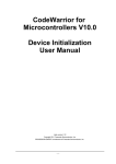
1
Purchase Agreement
P&E Microcomputer Systems, Inc. reserves the right to make changes without further notice to any
products herein to improve reliability, function, or design. P&E Microcomputer Systems, Inc. does not
assume any liability arising out of the application or use of any product or circuit described herein.
This software and accompanying documentation are protected by United States Copyright law and
also by International Treaty provisions. Any use of this software in violation of copyright law or the
terms of this agreement will be prosecuted.
All the software described in this document is copyrighted by P&E Microcomputer Systems, Inc.
Copyright notices have been included in the software.
P&E Microcomputer Systems authorizes you to make archival copies of the software and
documentation for the sole purpose of back-up and protecting your investment from loss. Under no
circumstances may you copy this software or documentation for the purpose of distribution to others.
Under no conditions may you remove the copyright notices from this software or documentation.
This software may be used by one person on as many computers as that person uses, provided that
the software is never used on two computers at the same time. P&E expects that group programming
projects making use of this software will purchase a copy of the software and documentation for each
user in the group. Contact P&E for volume discounts and site licensing agreements.
P&E Microcomputer Systems does not assume any liability for the use of this software beyond the
original purchase price of the software. In no event will P&E Microcomputer Systems be liable for
additional damages, including any lost profits, lost savings or other incidental or consequential
damages arising out of the use or inability to use these programs, even if P&E Microcomputer Systems
has been advised of the possibility of such damage.
By using this software, you accept the terms of this agreement.
© 2009 P&E Microcomputer Systems, Inc. “MS-DOS” and “Windows” are registered trademarks of
Microsoft Corporation. “Freescale” and “ColdFire” are registered trademarks of Freescale, Inc. “IBM”
and “PowerPC” are registered trademarks of IBM corporation.
P&E Microcomputer Systems, Inc.
98 Galen St.
Watertown, MA 02472
617-923-0053
http://www.pemicro.com
Manual version 1.02
1
2
INTRODUCTION ............................................................................................ 1
1.1
Overview ........................................................................................................ 1
1.2
Package Contents .......................................................................................... 1
1.3
Supported Devices ......................................................................................... 1
1.4
Recommended Materials On The Getting Started DVD-ROM ....................... 1
1.5
Handling Precautions ..................................................................................... 2
HARDWARE FEATURES............................................................................... 2
2.1
DEMOEM Base Board Features .................................................................... 2
2.2
On-Board Logic Analyzer ............................................................................... 7
2.3
On-Board Virtual USB Port............................................................................. 7
2.4
DEMOEM Daughter Card Features ............................................................... 8
2.5
DEMOEM Jumper/Connector Quick Reference............................................. 8
3
GETTING STARTED WITH THE DEMOEM................................................. 11
4
SYSTEM SETUP .......................................................................................... 11
5
6
7
4.1
Overview ...................................................................................................... 11
4.2
Operating System Requirements ................................................................ 12
4.3
Software Setup............................................................................................. 12
4.4
Quick Startup................................................................................................ 13
4.5
Hardware Setup ........................................................................................... 13
OPERATING MODES................................................................................... 16
5.1
Overview ...................................................................................................... 16
5.2
Debug Mode................................................................................................. 16
5.3
Run Mode..................................................................................................... 17
5.4
External BDM Mode ..................................................................................... 17
P&E EMBEDDED MULTILINK TOOLKIT PC APPLICATIONS .................... 17
6.1
Logic Analyzer Application ........................................................................... 17
6.2
Terminal Application..................................................................................... 18
6.3
DEMOEM Unsecure Application .................................................................. 19
6.4
Serial Grapher Application ........................................................................... 20
JUMPER SETTINGS .................................................................................... 24
DEMOEM User Manual
ii
8
9
10
iii
7.1
System Power...............................................................................................24
7.2
Virtual Serial Port ..........................................................................................25
7.3
Serial Port .....................................................................................................26
7.4
SPI Port ........................................................................................................26
7.5
EEPROM Enable ..........................................................................................27
7.6
LED Display Port ..........................................................................................27
7.7
IR Interface ...................................................................................................28
7.8
External Crystal Circuitry ..............................................................................29
7.9
P&E’s Input Capture Header ........................................................................29
7.10
LCD Module ..................................................................................................30
7.11
P&E Light Touch Switch Enable Header ......................................................30
7.12
Differential Analog Channel Inputs ...............................................................30
7.13
Touch Pads...................................................................................................32
7.14
QE8-Related Jumper Settings ......................................................................32
7.15
VBAT Header................................................................................................33
7.16
Piezo Buzzer.................................................................................................34
7.17
Optional Jumpers For Various VDD And VSS ..............................................34
DEMOEM CODE DEVELOPMENT SOFTWARE......................................... 34
8.1
Using CodeWarrior With The DEMOEM.......................................................34
8.2
Using P&E Software With The DEMOEM.....................................................35
TRANSITIONING TO YOUR OWN TARGET ............................................... 35
9.1
Hardware Solutions At A Glance ..................................................................36
9.2
Working With P&E’s USB Multilink ...............................................................37
9.3
Working With P&E’s Cyclone PRO ...............................................................38
TROUBLESHOOTING.................................................................................. 39
10.1
DEMOEM Is Undetected ..............................................................................39
10.2
CodeWarrior Installation Fails (WinDriver Error)...........................................40
DEMOEM User Manual
1
1.1
INTRODUCTION
Overview
The DEMOEM is a low cost development system supporting Freescale
MCF51EM256 and MCF51EM128 microcontrollers. It consists of a DEMOEM
Base Board and a DCF51EM256 Daughter Card. P&E’s Embedded Multilink
circuitry on the DEMOEM board allows the processor connected to the
DEMOEM to be debugged and programmed via USB from a PC. In addition,
the demo board can be powered using the USB bus.
1.2
Package Contents
The DEMOEM package includes the following items:
1.3
•
DEMOEM Base Board with a DCF51EM256 Daughter Card installed
•
Getting Started DVD - Getting started with the series of
microcontrollers
•
USB A-to-B Cable
•
Quick Start Guide
•
Freescale Warranty Card
Supported Devices
The DEMOEM supports the following devices:
1.4
•
MCF51EM256
•
MCF51EM128
Recommended Materials On The Getting Started DVD-ROM
•
DEMOEM User Manual
Freescale MCF51EM256 reference manual and datasheet
1
1.5
•
DEMOEM Base Board and Daughter Card schematic
•
P&E Embedded Multilink Toolkit applications
•
P&E Embedded Multilink driver installation guide and resources
Handling Precautions
Take care to handle the package contents, including the DEMOEM Base
Board and DCF51EM256 Daughter Card, in a manner such as to prevent
electrostatic discharge.
2
HARDWARE FEATURES
The DEMOEM is a demonstration and development system for Freescale’s
MCF51EM256 microcontrollers. Application development is quick and easy
using P&E’s Embedded Multilink circuitry and the included software tools and
examples. An optional BDM port is provided to allow the use of an external
BDM interface such as P&E’s Cyclone PRO automated programmer or USB
Multilink. The USB Multilink is functionally comparable to the DEMOEM’s
Embedded Multilink circuitry.
Note:
2.1
The DEMO board’s onboard Embedded Multilink circuitry is intended to
function with the onbaord processor and any daughter cards that may be
included. It cannot be used to communicate with other devices.
DEMOEM Base Board Features
•
On-board Logic Analyzer
•
On-board Virtual Serial Port
•
Four (4) asymmetrically positioned 13x2 male connectors for
interchangeable daughter cards
•
P&E’s Embedded Multilink circuitry populated on the underside
•
SCI signals connected to P&E’s Embedded Multilink through jumpers
Board:
•
2
Mother/daughter card approach. Daughter card contains only MCU
and power bypass caps:
DEMOEM User Manual
•
•
Connectors for MCF51EM256 100-pin LQFP (DCF51EM256)
•
PCB coloring:
•
Black-colored mother board
•
Red-colored daughter card
Freescale Form Factor Parameters must be followed
•
50-pin (2x25-pin) connector labeled MCU_PORT (J1) to bring out
some device signals
•
MCU_PORT (J1) has a (2.54 pitch, dual row) through-hole
Female connector: 2x25 Socket Header, Pass Thru, .1", Bottom
Entry, SMT
BDM interface:
•
Integrated P&E Embedded Multilink Circuitry
•
•
MDI interface features:
•
SCI signals from Embedded Multilink connected through
jumper to SCI1 or SCI3 pins of EM MCU
•
“Logic analyzer” inputs to timer channels of Embedded
Multilink to header pins
Embedded Multilink design populated on bottom of board
•
BDM Connector (6-pin Header) (not populated)
•
Jumpers (J39 and J40) to select programming the MCU daughter
card or the MC9S08QE8 on the DEMOEM
Power:
•
Power LED
•
Board power via the USB connection
•
On board Voltage Regulator with 3.3V output to MCU
•
Barrel style power connector (2.1 mm)
•
AAA battery holder for 2 batteries. (Alternate board power supply).
•
Power switch for all board power
DEMOEM User Manual
3
•
Layout for jumper from board VDD to MCU VDD pins, with layout for
an optional zero ohm resistor to permanently connect these signals.
•
Layout for jumper from MCU VDD to MCU VDDA and from MCU VSS
to MCU VSSA pins, with populated zero ohm resistor shorting jumper
pins.
•
Layout for jumper from MCU VDDA to MCU VREFH and from MCU
VSSA to MCU VREFL pins, with populated zero ohm resistor shorting
jumper pins
•
All power traces are minimum double width
•
Four test points for GND
•
Four test point for VDD
•
Voltage input jumpers
•
•
powered DEMO via on-board voltage regulator (3.3V)
•
powered DEMO via on-board USB BDM (3.3V)
•
powered DEMO via on-board battery (3.0V)
•
supply 3.3V power to the MCU_PORT header if the board is
powered though the on-board regulator or USB
Noise filter in the VDD to VDDA, VSS and VSSA connection in order
to improve ADC accuracy
MCU:
•
Reset switch with optional LED indicator.
•
IRQ Button
•
Crystal circuit for 32kHz to 16MHz crystal for XOSC2 input (not
populated)
•
4
•
Use circuit components recommended by crystal manufacturer
and MCU data sheet.
•
Footprint for jumpers to disable XTAL from MCU
•
0 ohm resistors in parallel with jumper footprints to connect XTAL
circuit
Jumpers to disable all the user I/O functions from additional circuitry
DEMOEM User Manual
LCD and UI:
•
3V LCD Glass
•
Jumpers (J25) to configure front and back plane selection
•
4 Buttons
•
4 LEDs
•
4 Touch cap pads (require software developed for touch sensing with
standard I/Os)
Independent RTC:
•
Coin-cell (CR2032) lithium battery holder with connection to
MCF51EMxx VBAT pin
•
Tamper button connected to TAMPER pin
•
32.768 kHz Crystal with its circuitry connected in EXTAL1 and XTAL1
pins
•
Optional crystal footprint on DCF51EM256 daughter card (not
populated)
•
Piezo buzzer for IRTC alarm
Analogue Signal Syntheses:
•
MC9S08QE8 (20-pin SOIC) with:
•
Three Potentiometers
•
6 PWM outputs with low-pass filters in order to generate 60/50 Hz
signals connected to Nucleus ADC inputs via jumpers
•
6 LEDs, one for each PWM output
•
1 LED connected to a GPIO
•
3 buttons
Serial Communication:
•
DEMOEM User Manual
IR interface (Tx and Rx). Connected with SCI1. (External circuitry
5
designed to use the internal PRACMP for Rx and considering higher
current capability in the Tx pin)
•
RS-232 circuitry with BD9 connector connected to SCI3 through
jumpers (whole circuit not populated)
•
Drive four 5V LEDs using MCF51EMxx PTE4, PTE5, PTA5, and
PTA6, jumper for disabling connection
•
EEPROM serial SPI1 memory for NVM data storage
•
Header pins for user connector or convenient monitoring of every
serial port
•
Specifications:
•
Board Size 6.0 x 4.5
•
Daughter Card Size 2.0 x 2.1
•
Power Input:
•
•
6
USB Cable: 5VDC, 500mA max
DC Power Jack: 2.1/5.5mm barrel connector, 6VDC Center
Positive
DEMOEM User Manual
Figure 2-1: DEMOEM Top Component Placement
2.2
On-Board Logic Analyzer
The DEMOEM board has a built-in 2-channel logic analyzer which may be
used to display captured data in real-time on a host PC. The logic analyzer
channels (IN0/IN1) are connected to the PTA5 and PTA6 signals on the
DEMOEM board by default via the J41 jumpers. The channels may be
connected to any of the processor pins via wire jumpers (not included).
The Logic Analyzer Utility, included in the P&E Embedded Multilink Toolkit on
the accompanying DVD-ROM, displays the logic analyzer signals on a PC.
2.3
On-Board Virtual USB Port
The DEMOEM board has a built-in virtual serial port which may be connected
to the EM processor’s SCI RXD/TXD. This allows certain PC applications to
be able to connect in a serial fashion to the microcontroller without the actual
use of serial port hardware.
The Terminal Window Utility, included in the P&E Embedded Multilink Toolkit
on the accompanying DVD-ROM, is a generic serial port utility which works
with the DEMOEM virtual serial port or actual serial port hardware.
DEMOEM User Manual
7
2.4
2.5
DEMOEM Daughter Card Features
•
Four (4) bottom-mounted asymmetrically positioned 13x2 female
connectors to mate with the DEMOEM Base Board
•
A top-mounted MCF51EM256 chip
DEMOEM Jumper/Connector Quick Reference
Default Jumper Settings
The following is a list of default jumper settings for DEMOEM board. The
settings listed indicate the “on” (or installed) position. More detailed
description of the jumper settings are available in Section 7 - JUMPER
SETTINGS.
Default Jumper Settings
JUMPERS
8
SETTINGS
DESCRIPTION
J3
2&3
Power Source
J4
1&2, 5&6
VDD_SELECT
J5
ALL OFF
SCI1
J6
ALL OFF
SCI3
J7
ALL OFF
Virtual Serial Rx Enable
J8
ALL OFF
Virtual Serial Tx Enable
J9
ALL OFF
SCI1/SCI3 Tx Select
J10
ALL OFF
SCI1/SCI3 Rx Select
J11
ALL OFF
SPI1
J12
ALL OFF
SPI2
J13
ALL OFF
SPI3
J14
ALL ON
EEPROM Enable
DEMOEM User Manual
Default Jumper Settings
DEMOEM User Manual
J15
ALL ON
Port E LED Enable
J16
ALL ON
Infrared Comm Enable
J17
ALL OFF
XOSC2 Enable
J18
ALL ON
P&E Logic Analyzer
J19
Not Populated
MCU_VSSA
J20
Not Populated
MCU_VREFL
J21
1&2
MCU_VDD
J22
Not Populated
MCU_VDDA
J23
Not Populated
MCU_VREFH
J24
1&2
MCU_PORT_VDD
J25
2&4, 3&5
LCD Plane Selection
J26
ALL ON
LCD Pin Connections
J27
ALL ON
LCD Pin Connections
J28
ALL ON
Touch Switches Enable
J29
ALL ON
DADMx to GND
J31
2&3
IRQ Pull-Up, Pull-Down
J32
1&2
IRQ Switch Enable
J33
ALL ON
Reset Switch, LED
Enable
J34
1&2
Tamper Switch Enable
J35
ALL ON
Touch-Pad Enable
9
Default Jumper Settings
10
J36
1&2
QE8 Vdd
J37
OFF
IRTC VBAT Supply
J38
ALL ON
QE8 PWM to ADC
J39
1&2
Debug Reset EM/QE
J40
1&2
Debug BKGD EM/QE
J41
ALL ON
PTA LED Enable
J42
1&2
PTB0 IR Capacitor
J43
1&2
PTB0 IR Enable
J44
1&2
Piezo Buzzer Enable
DEMOEM User Manual
MCU Port Connector Pinout
The following is the pinout for the MCU Port connector on the DEMOEM
board.
Figure 2-2: MCU Port Connector Pinout
3
GETTING STARTED WITH THE DEMOEM
The DEMOEM is a low-cost board targeting quick microcontroller evaluation.
Please refer to the DEMOEM Quick Start Guide and Labs for instructions on
how to install software, connect the DEMOEM to your PC, and run quick
demonstrations.
4
4.1
SYSTEM SETUP
Overview
P&E’s Embedded Multilink driver is required to operate the DEMOEM using a
PC. The Embedded Multilink driver should be installed with the CodeWarrior
DEMOEM User Manual
11
Development Studio software or from the DEMOEM Resources in the Getting
Started DVD-ROM before the PC is connected to the DEMOEM.
4.2
Operating System Requirements
The following are the resources required to run the CodeWarrior Development
Studio and the DEMOEM:
4.3
4.3.1
•
PC-compatible system running Windows 2000, Windows XP, or
Windows Vista
•
128MB of available system RAM, and 1GB of available hard disk
space
•
DVD-ROM drive for software installation
•
USB port
Software Setup
Installing CodeWarrior Development Studio
To install the CodeWarrior Development Studio, follow the instructions on the
DVD-ROM.
4.3.2
Installing P&E Resources
Use the DEMOEM Resources in the DVD-ROM to access and install P&E
resources for the DEMOEM. These materials are not required for operation.
The DEMOEM Resources in the Getting Started DVD-ROM contains the
following support materials:
12
•
DEMOEM Embedded Multilink hardware interface driver
•
DEMOEM User Manual (this document)
•
DEMOEM Base Board and Daughter Cards Schematics
•
DEMOEM Component Breakdown List
•
P&E Embedded Multilink Toolkit PC Applications
•
P&E Evaluation Software
•
Links to Freescale documentation, P&E Discussion Forums, and
DEMOEM FAQs.
DEMOEM User Manual
4.4
Quick Startup
Only a few steps are required to get the DEMOEM up and running. Please
reference the Quick Start Guide.
4.5
4.5.1
Hardware Setup
First-Time Connection
The DEMOEM may be connected to a PC through a USB port. Connection
steps are listed below in typical order:
1. Install the required software, as described in the previous section.
2. Make sure that jumpers J3 and J4 are configured per the default settings described in Section 2.5 - DEMOEM Jumper/Connector
Quick Reference.
3. Connect the DEMOEM Base Board to the PC via the USB cable.
4. The operating system will recognize P&E’s Embedded Multilink circuitry and P&E’s USB to Serial circuitry. Depending on the operating
system, you may see the “Found New Hardware Wizard” dialog to
assist you with software installation for “PEMicro USB Multilink (i0).”
On Windows XP (SP2), the following dialog will appear:
DEMOEM User Manual
13
Figure 4-1: Found New Hardware Wizard Dialog (1 of 4)
Select the “Install the software automatically (Recommended)” option
and click the “Next” button.
5. Windows will install the driver files to your system. At the end of the
installation, the following dialog box will appear:
Figure 4-2: Found New Hardware Wizard Dialog (2 of 4)
Click the “Finish” button to exit the current “Found New Hardware
Wizard”.
6. Depending on the operating system, you may see the “Found New
Hardware Wizard” dialog again to assist you with software installation
for “PEMicro USB Serial Port (i1).” On Windows XP (SP2), the following dialog will appear:
14
DEMOEM User Manual
Figure 4-3: Found New Hardware Wizard Dialog (3 of 4)
Select the “Install the software automatically (Recommended)” option
and click the “Next” button.
7. Windows will install the driver files to your system. At the end of the
installation, the following dialog box will appear:
DEMOEM User Manual
15
Figure 4-4: Found New Hardware Wizard Dialog (4 of 4)
Click the “Finish” button to exit the “Found New Hardware Wizard.”
If the DEMOEM hardware interface driver is now properly installed on your
system, the green USB LED (D1000) on the DEMOEM Base Board should be
illuminated. In addition, if you turn on the system power of the DEMOEM you
will see the red Power LED (D2) illuminate.
5
5.1
OPERATING MODES
Overview
The DEMOEM’s Embedded Multilink circuitry, featured hardware
components, and optional external BDM header make it a versatile
development tool. Below are some of the featured operating modes of the
DEMOEM.
5.2
Debug Mode
A host communicates with the DEMOEM through the Embedded Multilink
circuitry. Either the CodeWarrior Development Studio or P&E’s HCS08/CFV1
software tools will work with the DEMOEM. Please refer to Section 8 -
16
DEMOEM User Manual
DEMOEM CODE DEVELOPMENT SOFTWARE for more information.
5.3
Run Mode
The DEMOEM’s rich component list empowers it to perform a variety of tasks.
Once an application is developed, debugged, and programmed properly into
the EM internal flash memory, it can run with or without connecting to a host.
5.4
External BDM Mode
The DEMOEM has an optional BDM header for debugging and programming
the on-board EM device using an external BDM hardware tool, such as P&E’s
USB Multilink or Cyclone PRO. Please refer to Section 9 - TRANSITIONING
TO YOUR OWN TARGET for more information. A user can take advantage of
this mode to develop a target-specific EM system and compare it with the
DEMOEM when necessary.
6
P&E EMBEDDED MULTILINK TOOLKIT PC APPLICATIONS
P&E provides several Windows PC-based applications which work with the
DEMOEM board. These applications are collectively referred to as the P&E
Embedded Multilink Toolkit. The following applications are included in the
toolkit:
6.1
Logic Analyzer Application
The DEMOEM board has a built-in two-channel logic analyzer. This analyzer
allows the IN0 and IN1 signals to be captured by the PC and displayed for the
user. The IN0 and IN1 signals may be connected to any of the MCU signals
which the user would like to view. By default, they are connected to the PTA5
and PTA6 pins of the MCU by jumper J18. At the time of this release, the logic
analyzer runs at a capture rate of 10KHz.
DEMOEM User Manual
17
Figure 6-1: Logic Analyzer Application
This PC-based application is used to display the logic analyzer data on the
PC. The logic analyzer data is displayed in real-time and each waveform may
be paused, zoomed, and printed.
To start using this application, please plug in a USB cable into the DEMOEM
board. Once the USB and Power LEDs light up, indicating the proper
enumeration on the USB port, click on the Open DEMO and Graph Pins
button. The logic channel graphs should be reflecting data captured from the
IO pins connected to the IN0 and IN1 header pins on the DEMOEM
evaluation board.
This PC-based application is included on the DVD-ROM that accompanies
the DEMOEM, and may also be found at:
http://www.pemicro.com/fixedlinks/demotoolkit.cfm.
6.2
Terminal Application
This PC-based application acts as a standard serial port terminal application
on the PC. It works with standard serial ports as well as the virtual serial port
on the DEMOEM board. The application includes settings to adjust the COM
port number, baud rate, parity, and number of data bits. There is a button to
take a file on the PC and transmit it out of the serial port. There are also
delays which are automatically inserted into the transmission output to
prevent overruns. It is recommended that these defaults not be changed.
18
DEMOEM User Manual
Figure 6-2: Terminal Application
The terminal window may be set for full duplex or half duplex. In full duplex
mode, only received characters are displayed in the terminal window. In half
duplex mode, both transmitted and received characters are displayed.
To start using this application, please choose COM or virtual USB COM
settings from the drop down Port menu. This specifies the port on the
evaluation board that will be used for serial data transmission. Please make
sure that the jumpers on header J7 and J8 are set accordingly. Prior to
starting serial data capture, please specify the Baud, Parity and Bits settings
to reflect the parameters at which your serial communication interface is
operating. Once your port settings are configured, please plug a USB or DB9
serial cable into the evaluation board and click on the Open Serial Port button.
This PC-based application is included on the DVD-ROM that accompanies
the DEMOEM, and may also be found at:
http://www.pemicro.com/fixedlinks/demotoolkit.cfm.
6.3
DEMOEM Unsecure Application
This application allows secure CFV1 and HCS08 microcontrollers to be
unsecured. The Unsecure application will erase a secure device to make it
unsecure. This application works with the DEMOEM board as well as other
user hardware connected to the PC via the USB Multilink or Cyclone PRO
hardware interfaces.
DEMOEM User Manual
19
Figure 6-3: Unsecure Application
In order to unsecure a device with this application, please specify the
hardware interface that you are using. If your P&E Multilink or Cyclone PRO is
successfully detected, the name of a corresponding device will appear in the
Port text box. Please select HCS08 or CFV1 from the Select Architecture drop
down menu and press the Perform Unsecure button. The application will
finish unsecuring and erasing the device shortly thereafter.
This PC-based application is included on the DVD-ROM that accompanies
the DEMOEM, and may also be found at:
http://www.pemicro.com/fixedlinks/demotoolkit.cfm.
6.4
Serial Grapher Application
This PC-based application is a generalized version that may be used with
custom microcontroller code which transmits data in the correct format. The
serial graphing utility allows incoming data on the PC serial port (or one of
P&E’s virtual serial ports) to be automatically graphed in time or displayed as
a series of bar graphs. The virtual serial port exists on several of P&E’s
Embedded Multilink designs including the DEMOEM board.
To start using this application, please choose COM or virtual USB COM
settings from the drop-down Port menu. By doing so, you are specifying the
port on the evaluation board that will be used for transmitting captured
accelerometer data via a COM or USB serial port. Please make sure that
jumpers J7 and J8 are set accordingly. Prior to starting serial data capture,
please specify the Baud setting to reflect the parameter at which your serial
communication interface is operating. Once your port settings are configured,
please plug a USB or DB9 serial cable into the evaluation board and click on
the Open Serial Port and Start Demo buttons. The graphing of data can be
20
DEMOEM User Manual
paused and the scale of the X and Y axes can be changed via a tool bar
located in the top right corner of the Serial Grapher Application.
All data to be displayed must be in hexadecimal format. The data can be
accepted and displayed either as incoming byte values ($00-$FF) or word
values ($0000-$FFFF). The data format indicates whether the data is byte or
word data. The graphical components automatically size their range
depending upon the incoming data.
This PC-based application is included on the DVD-ROM that accompanies
the DEMOEM and may also be found at:
http://www.pemicro.com/fixedlinks/demotoolkit.cfm.
6.4.1
Visual Components
The Bar Graph has four separate bars A, B, C, and D. On each bar a
percentage value is displayed which indicates the current value relative to the
full range. A byte value of $7F (max is $FF) would show up as approximately
50% as would a word value of $7FFF (max is $FFFF). As can be seen in the
data formatting section, all four bars must be written at the same time. The
bars are shown here:
DEMOEM User Manual
21
Figure 6-4: Serial Grapher Bar Graph
The graphing component shows four waveforms, X, Y, Z, and W. The
magnitude axis either has a range of $00-$FF (if byte values are incoming on
the serial port) or $0000-$FFFF (if word values are incoming). Each new set
of values which comes through the serial port is added to the far right side of
the graph and the rest of the data values are moved to the left. The vertical
axis displays the incoming data as the magnitude of each waveform, and the
horizontal axis displays the number of samples. The graph has a limited size,
so older samples will eventually fall off the left part of the graph. As can be
seen in Data Format, each incoming data command affecting the graphing
component must have new data for all four waveforms. An example graph is
shown here:
22
DEMOEM User Manual
Figure 6-5: Serial Grapher Graphing Component
6.4.2
Data Format
The data format is broken into two sections depending upon whether the
incoming data is in byte format or word format.
6.4.2.1
Byte Formatted Data
There are two commands which may be accepted. Both commands must end
in the special characters #$0D and #$0A which are CR (carriage return) and
LF (line feed). The accepted commands are:
WnnZnnYnnXnn
The nn values are 00-FF and correspond in order to the data displayed on the
following graph lines: W, Z, Y, X.
AnnBnnCnnDnn
The nn values are 00-FF and correspond in order to the data displayed on the
following bar graphs lines: A, B, C, D.
DEMOEM User Manual
23
6.4.2.2
Word Formatted Data
There are three commands which may be accepted. All commands must end
in the special characters #$0D and #$0A which are CR (carriage return) and
LF (line feed). The accepted commands are:
nnnn,nnnn,nnnn,nnnn
The nnnn values are 0000-FFFF and correspond in order to the data
displayed on both the graph and bar graphs as follows: X/A, Y/B, Z/C, W/D.
nnnn:nnnn:nnnn:nnnn
The nnnn values are 0000-FFFF and correspond in order to the data
displayed the graphing component as follows: X, Y, Z, W.
nnnn=nnnn=nnnn=nnnn
The nnnn values are 0000-FFFF and correspond in order to the data
displayed on the bar graph component as follows: A, B, C, D.
7
7.1
7.1.1
JUMPER SETTINGS
System Power
J3 - Power Source Selection
The EM processor may obtain its power from the on-board regulator, USB
port, external battery, or through MCU_PORT J1. The on-board regulator
obtains its input from a 2.1mm barrel connector. The on-board regulator can
regulate the output to 3.3V. Power input is selected by using the J3, J4, and
J24 headers.
Select the USB port to supply microcontroller VDD. This is the default setting.
Figure 7-1: Power Source Selection Header (J3)
24
DEMOEM User Manual
7.1.2
J4 - VDD Selection
Figure 7-2: VDD_SELECT Option Header (J4)
7.1.3
J24 - MCU PORT
Select the MCU_PORT to supply microcontroller VDD. This setting also
allows power to be supplied to the target connected to the MCU_PORT. By
default this jumper is installed.
Figure 7-3: MCU_PORT Header (J24)
7.2
Virtual Serial Port
The DEMOEM board has a built-in virtual serial port which may be connected
to the EM processor’s SCI or SCI3 Rx and Tx. This allows certain PC
applications to be able to connect in a serial fashion to the microcontroller
without the actual use of serial port hardware. It can be enabled or disabled
by installing or removing the jumpers of J7 and J8.
Figure 7-4: TX_EN Header (J7)
DEMOEM User Manual
25
Figure 7-5: RX_EN Header (J8)
7.3
Serial Port
Headers J5 and J6 provide convenient access points for SCI1 and SCI3
signals, respectively. J9 allows selection of the SCI1 or SCI3 TxD signal.
Header J10 is used to select the SCI1 or SCI3 RxD signal.
Figure 7-6: TX_SEL Header (J9)
Figure 7-7: RX_SEL Header (J10)
Note:
7.4
The default connection is to the SCI3 signals.
SPI Port
The DEMOEM board provides three headers for convenient access to SPI
module signals: J11 for SPI1, J12 for SPI2, and J13 for SPI3. The signals are
arranged as below:
26
DEMOEM User Manual
Figure 7-8: SPI Port Header
7.5
EEPROM Enable
The DEMOEM includes a serial SPI memory for non-volatile data storage.
Header J14 configures control signals for the EEPROM IC (U4).
Figure 7-9: EEPROM Enable (J14)
7.6
LED Display Port
The DEMOEM has 4 LEDs connected to signals PTE4, PTE5, PTA5, and
PTA6 that may be driven by 5V. They can be enabled or disabled by installing
or removing the corresponding jumpers, J15 & J41, in the LED_EN header.
7.6.1
J15 - LED Display Enable Port Port 1 LED_ENABLE1
Enables port connections PTE5 and PTE4 to LED circuits. This is the default
setting.
Figure 7-10: LED Display Enable Header LED_EN (J15)
DEMOEM User Manual
27
7.6.2
J41 - LED Display Enable Port Port 2 LED_ENABLE2
Enables port connections PTA5 and PTA6 to LED circuits. This is the default
setting.
Figure 7-11: LED Display Enable Header LED_EN (J41)
7.7
7.7.1
IR Interface
J16 - IR_EN Header
The DEMOEM includes an infrared communications interface whose signals
are connected with SCI1 and are jumper enabled by J16.
Figure 7-12: IR_EN Header (J16)
7.7.2
J42 - PTB0 IR Capacitor
Connects a 0.1 uF bypass capacitor to PTB0.
Figure 7-13: PTB0 IR Capacitor (J42)
7.7.3
J43 - PTB0 IR Enable
Connects PTB0 to the IR circuitry.
28
DEMOEM User Manual
Figure 7-14: PTB0 IR Enable (J43)
7.8
External Crystal Circuitry
The DEMOEM design incorporates, but has not populated, a crystal circuit for
XOSC2. Jumper 17 enables the EXTAL2 and XTAL2 signal connections when
populated.
Figure 7-15: External Crystal Circuitry CLK2_EN (J17)
7.9
7.9.1
P&E’s Input Capture Header
J18 - P&E’s Logic Analyzer Inputs IN0/IN1
The logic analyzer inputs are marked on one side of the J18 jumper. The
inputs allow P&E’s PC-based logic analyzer application to display these
signals in real-time.
By installing both jumpers, the logic analyzer pins IN0 and IN1 will be
connected to PTA5 and PTA6 respectively.
By removing these jumpers IN0 and IN1 will be unconnected. The
user may connect these signals, via wires, to any other signals on the
DEMOEM User Manual
29
processor which they wish to view on the PC.
Figure 7-16: Jumper Settings for Input Signals to P&E’s Embedded Multilink, P&E
INPUT_EN (J18)
7.10
LCD Module
The DEMOEM brings all LCD signals to two 22x2 headers, J26 and J27. By
default all jumpers are installed.
Header 25 is used to demonstrate FP/BP selection.
Figure 7-17: LCD Module Header (J25)
By default, LCD0 controls BP0 and LCD4 controls FP0.
7.11
7.11.1
P&E Light Touch Switch Enable Header
J28 - Light Touch Switch Enable KEY_EN
Figure 7-18: Jumper Settings for Light Touch Switch Enable KEY_EN (J28)
Enables the corresponding switch. Each jumper may be individually
installed or removed. By default, all jumpers are installed to enable all
the switches.
7.12
Differential Analog Channel Inputs
The DEMOEM board brings DADM0, DADM1, and DADM2 signals to header
30
DEMOEM User Manual
29, which may be connected to GND by installing the jumpers. By default they
are connected to GND.
Figure 7-19: Differential Analog Channel Inputs Header DADMx (J29)
The DEMOEM board brings DADP0, DADP1, and DADP2 signals to header
38, which is shared with the LEDs for QE8.IRQ, RESET, and TAMPER
Buttons
7.12.1
J31 - IRQ Button
The DEMOEM board has an IRQ button enabled by jumper position 32. When
enabled it is connected to either a pullup or a pulldown resistor, determined by
jumper J31.
By default it is connected to a pulldown resistor.
Figure 7-20: IRQ Pull-Up/Pull-Down Enable (J31)
Figure 7-21: IRQ_EN (J32)
The DEMOEM board has a RESET button and LED enabled by Header J33.
DEMOEM User Manual
31
7.12.2
J33 - Reset Switch Enable and Reset LED Display Enable Jumper
RESET_EN
Enables the Reset Switch and the Reset LED Display. Each jumper
may be individually installed or removed. This is the default setting.
Figure 7-22: Reset Switch and Reset LED enable Jumper (J33)
7.12.3
J34 - Tamper Button Enable
The DEMOEM has a Tamper button enabled by jumper 34.
Figure 7-23: Tamper Button Enable Jumper (J34)
7.13
Touch Pads
The DEMOEM implements 4 touch pads, enabled by jumper J35.
Figure 7-24: Touch Pad TPx_EN Header (J35)
7.14
QE8-Related Jumper Settings
The DEMOEM incorporates a QE8 device, which obtains power from jumper
J36. Its 6 PWM channels are connected via jumper J38 to DEMOEM ADC
inputs. Its BKGD and Reset debugging signals are selected via jumpers J39
and J40. Please see the corresponding section for the header definition.
32
DEMOEM User Manual
Figure 7-25: QE8 Device Power QE_VDD (J36)
Figure 7-26: PWM to ADC Header (J38)
7.14.1
Debugging Signal Selection Headers
Figure 7-27: Reset Selection (J39)
Figure 7-28: BKGD Selection (J40)
7.15
VBAT Header
The DEMOEM provides a configurable connection from the coin-cell CR2032
battery to the IRTC supply pin, via jumper 37. If a jumper is installed, the cell
battery will provide power to the VBAT pin of the daughter card MCU.
DEMOEM User Manual
33
7.16
Piezo Buzzer
Jumper 44 Connects PTE6 to the piezo buzzer circuitry.
Figure 7-29: Piezo Buzzer BUZ_EN (J44)
7.17
Optional Jumpers For Various VDD And VSS
The DEMOEM provides 5 jumpers, J19 through J23, for different VDD and
VSS connections on the bottom of the board. By default, they are not
populated and are shorted correspondingly with zero-ohm resistors in parallel,
except J21 which is populated. The user may take off the zero-ohm resistor
and install a corresponding jumper.
8
DEMOEM CODE DEVELOPMENT SOFTWARE
The DEMOEM includes P&E’s Embedded Multilink circuitry, so no external
hardware BDM tool is needed to debug and program the DEMOEM. A user
only needs to connect the DEMOEM to their PC to start developing code for it.
The DEMOEM package comes with an evaluation edition of Freescale’s
CodeWarrior studio. In addition, P&E’s evaluation software for HCS08 and
ColdFire® V1 is available in the DEMOEM Resources section of the Getting
Started DVD, or online at www.pemicro.com. A user may use either
CodeWarrior or P&E software tools to develop code for the DEMOEM.
8.1
Using CodeWarrior With The DEMOEM
The CodeWarrior for Microcontrollers studio supports Freescale’s HCS08 and
ColdFire V1 devices. It offers C, C++, and assembly-level support, and
provides debugging capabilities based on P&E’s debug and programming
technologies.
A programming or debug session with the project-based CodeWarrior IDE
may be launched by double-clicking on the project name (the format is
projectname.mcp) from your file storage. The DEMOEM tutorials, FAQs, and
quick start guide are easy to follow and will allow you use pre-built templates
34
DEMOEM User Manual
to begin creating a new project in a short time.
8.2
Using P&E Software With The DEMOEM
P&E offers software tools for Freescale’s HCS08 and ColdFire V1 devices
that can be used to develop code for the DEMOEM board.
8.2.1
P&E Software Tools for HCS08 Microcontrollers
For Freescale’s HCS08 devices, P&E offers an integrated development
environment, which combines a command-line assembler, in-circuit debugger,
and flash memory programmer. The assembler includes features such as a
full string replacement macro, conditional assembly, include files, and more.
The debugger supports both assembly and C source-level debugging. The
programmer can program/reprogram both internal and external flash devices
in-circuit.
8.2.2
P&E’s Software Tools for ColdFire® V1 Microcontrollers
P&E offers an integrated development environment for Freescale’s ColdFire
V1 devices, which combines a GNU C compiler, in-circuit debugger, and flash
memory programmer. The debugger supports both assembly and C sourcelevel debugging. The programmer can program/reprogram both internal and
external flash devices in-circuit.
9
TRANSITIONING TO YOUR OWN TARGET
Once you have finished working with the DEMOEM and are ready to build
your own target, you will need a hardware tool to allow you to develop using
your own board. P&E’s USB Multilink and P&E’s Cyclone PRO offer two
effective solutions, depending on your needs. Both work with Freescale’s
CodeWarrior as well as P&E software, and both provide a seamless transition
to working with your own hardware.
The USB Multilink is a development tool that is functionally comparable to the
Embedded Multilink circuitry on the DEMOEM. It will enable you to debug
your code and program it onto your target. The Cyclone PRO is a more
versatile and robust development tool with advanced features and production
capabilities.
More information is available below to assist you in choosing the appropriate
development tool for your needs.
DEMOEM User Manual
35
9.1
Hardware Solutions At A Glance
The USB Multilink offers an affordable and compact solution for your
development needs, and allows debugging and programming to be
accomplished simply and efficiently. Those doing rapid development will find
the USB Multilink easy to use and fully capable of fast-paced debugging and
programming.
The Cyclone PRO is a more complete solution designed for both development
and production. The Cyclone PRO features automated power switching,
multiple communications interfaces (including USB, Ethernet, and Serial),
stand-alone programming functionality, and many other advanced
capabilities.
Below is an overview of the features and intended use of the USB Multilink
and Cyclone PRO.
9.1.1
9.1.2
USB Multilink Key Features
•
Direct user control of target’s execution
•
Programming and debugging capabilities
•
Read/write registers and memory values
•
Compact and lightweight
•
Communication via USB 2.0
•
Supported by P&E software and Freescale’s CodeWarrior
Cyclone PRO Key Features
Advanced programming and debugging capabilities, including:
36
•
PC-Controlled and User-Controlled Stand-Alone Operation
•
Interactive Programming via Host PC
•
In-Circuit Debugging, Programming, and Testing
•
Compatible with Freescale’s ColdFireV1, HCS08, RS08, and
HC(S)12(X) microcontroller families
•
Communication via USB, Serial, and Ethernet Ports
•
Multiple image storage
•
LCD screen menu interface
DEMOEM User Manual
•
9.2
Supported by P&E software and Freescale’s CodeWarrior
Working With P&E’s USB Multilink
Figure 9-1: P&E’s USB Multilink (USB-ML-12 shown)
9.2.1
Product Features & Implementation
P&E’s USB Multilink Interface (USB-ML-12) connects your target to your PC
and allows the PC access to the Background Debug Mode (BDM) on
Freescale’s ColdFireV1, HCS08, RS08, and HC(S)12(X) microcontrollers. It
connects between a USB port on a Windows 2000/XP/2003/Vista machine
and a standard 6-pin debug connector on the target.
By using the USB Multilink Interface, the user can take advantage of the
background debug mode to halt normal processor execution and use a PC to
control the processor. The user can then directly control the target’s
execution, read/write registers and memory values, debug code on the
processor, and program internal or external FLASH memory devices.The
USB Multilink enables you to debug, program, and test your code on your
board.
9.2.2
Software
The USB Multilink Interface works with Codewarrior as well as P&E’s in-circuit
debugger and flash programmer to allow debug and flash programming of the
target processor. P&E’s USB Multilink Development Packages come with the
USB Multilink Interface, as well as flash programming software, in-circuit
debugging software, Windows IDE, and register file editor.
DEMOEM User Manual
37
9.3
Working With P&E’s Cyclone PRO
Figure 9-2: P&E’s Cyclone PRO
9.3.1
Product Features & Implementation
P&E’s Cyclone PRO is an extremely flexible tool designed for debugging,
testing, and in-circuit flash programming of Freescale’s ColdFireV1, HC08,
HCS08, RS08, and HC(S)12(X) microcontrollers. The Cyclone PRO connects
your target to the PC via USB, Ethernet, or Serial Port and enables you to
debug your code, program, and test it on your board. After development is
complete the Cyclone PRO can be used as a production tool on your
manufacturing floor.
For production, the Cyclone PRO may be operated interactively via Windowsbased programming applications as well as under batch or .dll commands
from a PC. Once loaded with data by a PC it can be disconnected and
operated manually in a stand-alone mode via the LCD menu and control
buttons. The Cyclone PRO has over 3Mbytes of non-volatile memory, which
allows the on-board storage of multiple programming images. When
connected to a PC for programming or loading it can communicate via the
ethernet, USB, or serial interfaces.
9.3.2
Software
The Cyclone PRO comes with intuitive configuration software and interactive
programming software, as well as easy to use automated control software.
The Cyclone PRO also functions as a full-featured debug interface, and is
supported by Freescale’s CodeWarrior as well as development software from
P&E.
P&E’s Cyclone PRO is also available bundled with additional software as part
of various Development Packages. In addition to the Cyclone PRO, these
38
DEMOEM User Manual
Development Packages include in-circuit debugging software, flash
programming software, a Windows IDE, and register file editor.
10
10.1
TROUBLESHOOTING
DEMOEM Is Undetected
Q: The connection assistant indicates that my DEMOEM is undetected even
though I have connected the hardware to my USB port. What should I do?
A: The connection assistant, which displays in either Codewarrior or P&E’s
development software, is a dialog which allows the user to connect to the
DEMOEM hardware. If this dialog indicates that the DEMOEM hardware is
not connected to the PC, the first step is to make sure that the DEMOEM
hardware is connected to the PC via a USB 2.0 high-speed cable. If it is
connected, unplug and then plug in the USB cable on the DEMOEM board
and click refresh in the connection assistant. If the hardware still does not
show up, try the following remedies:
(A) Re-Enable the USB driver
If you connected the DEMOEM interface prior to the installation of P&E’s
Embedded Multilink drivers, Windows will not have been able to find the
appropriate driver and may have disabled the device. The DEMOEM board
shows up in Window’s device manager as a “P&E Multilink,” since it contains
P&E’s Embedded Multilink circuitry. If you unplug and then plug in the device,
Windows will automatically disable it even if you have installed the drivers. To
force windows to try to load the driver again, perform the following steps while
the DEMOEM interface is connected to the computer:
1. Open the Control Panel (Start Button->Settings->Control Panel)
2. Double Click the "System" Icon
3. Select the "Hardware" tab
4. Click the "Device Manager" Button
5. The "P&E Multilink" device will be shown with an exclamation mark
next to it. Double-click this device.
6. Click the "Reinstall Driver…" button and follow the dialog instructions
to have Windows automatically install the driver.
(B) Re-Install the USB driver
DEMOEM User Manual
39
If the Multilink device does not show up in the device manager, use the driver
installation utility located in the DEMOEM Resources on the DVD-ROM. After
driver installation, unplug the DEMOEM from the PC and reboot the PC.
When the reboot has completed, connect the interface to the PC with the USB
2.0 cable. Run the software again to see if the interface is now detected.
If you have an error attempting to install the drivers, please view the
installation troubleshooting FAQ on P&E’s website at:
http://www.pemicro.com/faqs/faq_view.cfm?id=89.
(C) Test for installation of the USB driver files
To test the driver installation, use the driver test utility in the DEMOEM
Resources of the DVD-ROM to make sure all files were properly installed.
This may give some indication of what the problem is.
(D) Using a USB Hub
The DEMOEM is a high-power USB device. If a USB Hub is used, it must be a
self-powered hub (i.e., with its own power supply). If the Hub is not selfpowered the DEMOEM will not work. In general, USB ports located directly on
the PC are high-power (self-powered) ports.
10.2
CodeWarrior Installation Fails (WinDriver Error)
Q: When I try to install the Codewarrior or P&E software, installation fails with
this message: “There are currently 2 open applications using WinDriver.
Please close all applications and press Retry. To reload WinDriver, press
Cancel and reboot.” How do I solve this?
A: Some software applications on your PC are connected to the WinDriver
system driver which manages P&E's USB connections. This system driver
needs to be disabled for the installation to continue. Directions to disable
Windriver are as follows:
In Windows Explorer, right-click on My Computer and select Properties from
the drop-down menu.
1. Select the Hardware tab.
2. Click on the Device Manager button.
3. Select the "System Devices" in the Device Manager window.
4. Expand the tree index (+) for System Devices.
5. At the bottom of the System Devices list you should see the Win-
40
DEMOEM User Manual
Driver item.
6. Right-click on WinDriver and select Disable from the drop-down
menu.
7. Click Yes/OK when the confirmation dialog appears.
WinDriver is now disabled and you should be able to complete the installation.
After the installation finishes, you should re-enable the WinDriver system
driver using the following steps:
In Windows Explorer, right-click on My Computer and select Properties from
the drop-down menu.
1. Select the Hardware tab.
2. Click on the Device Manager button.
3. Select the "System Devices" in the Device Manager window.
4. Expand the tree index (+) for System Devices.
5. At the bottom of the System Devices list, you should see a WinDriver
item.
6. Right-click on WinDriver and select Enable from the drop-down
menu.
Reboot your PC after the installation finishes.
If you are unable to disable the WinDriver system driver in the above fashion,
you can delete the file c:\windows\system32\windrvr6.sys and then reboot
your machine. You should then re-run the installer and complete the
procedure. Reboot your machine after the installation has finished.
DEMOEM User Manual
41
42
DEMOEM User Manual