1
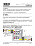
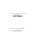
C L M - 6 11 C A M E R A L I N K M U LT I P L E X E R User’s Manual Document # 200686, Rev 0.1, 11/19/2010 (preliminary) Vivid Engineering 418 Boston Turnpike #104 • Shrewsbury, MA 01545 Phone 508.842.0165 • Fax 508.842.8930 Email [email protected] Web www.vividengineering.com Table of Contents 1. INTRODUCTION 1 1.1. Overview 1 1.2. Features 3 1.3. Functional Description 4 1.4. Camera Selection 1.4.1. Camera Select Switch 1.4.2. Baud Rate Switch 1.4.3. Serial Control 1.4.3.1. USB Support (Optional) 1.4.3.2. RS-232 Serial Port Communication 1.4.3.3. Camera Link Serial Communication 6 7 9 10 10 11 12 1.5. Typical Application 13 1.6. Specifications 14 INTERFACE 15 2. 2.1. Front Panel Connections 15 2.2. Rear Panel Connections 2.2.1. DB9 Connector Signals 16 17 2.3. Video Connector Signals 2.3.1. Cable Shield Grounding 18 18 3. MECHANICAL 21 3.1. Dimensions 21 3.2. External Power Supply 22 4. REVISION HISTORY 23 1. Introduction 1.1. Overview The CLM-611 Camera Link 1 Multiplexer interfaces up-to four Camera Link cameras of any configuration (base, medium, full, 80-bit) to one frame grabber using standard Camera Link cables. This capability supports applications requiring the ability to select between multiple cameras. The CLM-611 incorporates high-speed (85 MHz) interfaces and works with any Camera Link camera. The CLM-611 provides multiple camera selection methods including rear-panel switch settings, Camera Link interface signals (serial or camera control), and an external RS-232 port. An inexpensive optional adapter supports control of the CLM-611 via a PC USB port. Multiple CLM-611s may be cascaded to support more than four cameras. The CLM-611 Camera Link Multiplexer is housed in a sturdy, compact aluminum enclosure and is well suited for industrial and OEM applications. 1 The Camera Link interface standard enables the interoperability of cameras and frame grabbers, regardless of vendor. The Automated Imaging Association (AIA) sponsors the Camera Link program including the oversight Camera Link Committee, the self-certification program, and the product registry. The Camera Link specification may be downloaded from the AIA website, found at www.machinevisiononline.org Camera Link is a trademark of the Automated Imaging Association Windows is a trademark of Microsoft Corporation HyperTerminal is a trademark of Hilgraeve Inc. 1 Vivid Engineering Medium / Full Base FRAME GRABBER Camera Link Multiplexer Medium / Full CLM-611 Medium / Full Base Base CAMERA A CAMERA B 2 1.2. Features • Interfaces up-to four cameras to one frame grabber • Supports all Camera Link configurations (base, medium, full), including 80-bit • High-speed (85 MHz) design supports all Camera Link cameras • Multiple camera selection methods: - Camera Link interface serial messages - Camera Link interface Camera Control (CC) signals - Standard RS-232 port - Standard USB port (w/ optional adapter) - Fixed selection via switch settings • Passes all interface signals (video data, serial comm, camera control) • Minimal video data pass-through latency: 5 camera pixel clocks • Minimal control/communication pass-through latency: under 15 nS • May be cascaded to support greater than four cameras • LED camera select indicators • Sturdy, compact aluminum enclosure w/ mounting flange • Multi-nation power supply and RS-232 cable included • 3-year warrantee 3 1.3. Functional Description A block diagram of the CLM-611 is provided in Figure 1-1. The CLM-611 interfaces upto four base, medium, full, or 80-bit configuration Camera Link cameras to one frame grabber using standard Camera Link cables. This capability supports applications requiring the ability to select between multiple cameras. Two of the cameras, denoted A&B, connect to the front of the CLM-611 as does the frame grabber. The remaining two cameras, demoted C&D connect to the rear. The camera selection method is determined by the Camera Select switch located on the rear panel. The camera selection options are: • • • • Camera Link serial port messages Camera Link Camera Control signals (CC1/CC2 or CC3/CC4) External RS-232 (or USB w/ optional adapter) serial port messages Fixed selection (A,B,C, or D) When serial communication (Camera Link or RS-232/USB) is used to select the camera, the data rate is specified via the rear panel baud rate switch.. The baud switch enables the user to operate the CLM-611 at the same data rate as the camera, so camera and CLM-611 control messages can be combined on the same serial link. More details are provided in Section 1.4.3. The CLM-611 camera and frame grabber interfaces incorporate the connector, signals, pinout, and chipset in compliance with the Camera Link specification. The CLM-611 incorporates the “full” (i.e. dual cable) configuration signal set, consisting of video data, camera control, and serial communications. The CLM-611 also works with 80-bit, medium configuration and base configuration (single cable) configuration cameras. The CLM-611 incorporates high-speed (85 MHz) interfaces. The CLM-611 adds minimal delay (i.e. latency) to the video data path. This is an important criterion for time-critical applications. The latency through the CLM-611 is a fixed 5 pixel-clock delay. The pixel clock is established by the camera and can range from 20-85 MHz. Therefore, the CLM-611 fixed delay can range from 59 to 250 nS, depending on camera. The delay added by the CLM-611 for the camera control and serial communication signals is under 15 nS. LED camera select indicators are located next to the camera connectors to identify the current camera selection. Multiple CLM-611s may be cascaded to support more than four cameras. 4 The CLM-611 Camera Link Multiplexer is housed in a sturdy, compact aluminum enclosure. The CLM-611 is powered by an external multi-nation wall plug-in power supply which is included. Also included is an RS-232 serial cable. A Video Data Channel Channel Channel Link Link Link Receivers Receivers Receivers A Camera Control LVDS Xmtr A Serial Comm To Camera Link Cameras (4) B Camera Control B Serial Comm LVDS Xmtr Channel Channel Channel Link Link Link Receivers Receivers Receivers LVDS Xmtr C Camera Control LVDS Xmtr C Serial Comm Mux LVDS Rcvr Camera Control LVDS Rcvr LVDS Xmtr Channel Channel Channel Link Link Link Receivers Receivers Receivers Video Data Receivers Receivers LVDS Rcvr C Video Data Channel Channel Channel Link Link Link Transmitters Select Switches 1 LVDS Rcvr 2 0 Mux Control LVDS Xmtr 4 6 5 1 2 3 D Camera Control LVDS Xmtr D Serial Comm 4 6 5 RS-232 LVDS Rcvr LVDS Xmtr CLM-611 Camera Link Multiplexer Figure 1-1: CLM-611 Block Diagram 5 Serial Port To PC RS-232 Port (or USB via adapter) 7 D Video Data 3 7 0 Channel Channel Channel Link Link Link Receivers Receivers Receivers Serial Comm LVDS Xmtr To Camera Link Frame Grabber B Video Data LVDS Rcvr 1.4. Camera Selection The CLM-611 supports a variety of camera selection methods. The different methods are described in the following sections. The camera selection mode is determined by the camera select switch located on the rear panel. The rear panel also includes a baud rate switch for use with the serial control modes. The rear-panel switches are shown in Figure 1-2. CAMERA SELECT 0-A 4 - CC 1&2 1-B 5 - CC 3&4 2-C 6 - Serial 3-D 7 - RS-232 1 2 0 7 6 3 1 4 0 5 7 2 3 4 6 5 BAUD RATE 0 - 2400 4 - 38400 1 - 4800 5 - 57600 2 - 9600 6 - 115200 3 - 19200 7 - 230400 Figure 1-2: Rear-Panel Select Switches Note that camera selection changes are “hard” switches. The camera selection is performed immediately. As a precaution, care should be used to pause/halt the frame grabber while the switch is being made to avoid frame grabber malfunction. 6 1.4.1. Camera Select Switch The Camera select switch provides eight camera selection modes. The camera select modes are defined in Table 1-1. The selection modes are described in the following sections. Table 1-1: Camera Select Modes Camera Select Switch Mode 0 Camera A 1 Camera B 2 Camera C 3 Camera D 4 Camera Control CC1 & CC2 5 Camera Control CC3 & CC4 6 Camera Link serial link 7 RS-232 serial port (or USB) Switch positions 0-3 provide fixed camera A/B/C/D selection. Camera selection is fixed (static) and is unaffected by the camera control signal states or the serial control messages. Switch positions 4-5 enable camera selection based on the states of the Camera Control (CC) that are part of the Camera Link interface. Camera selection may be made by CC signals 1&2, or by 3&4. Camera Control signals 3&4 are often unused by the camera and are available for controlling the multiplexer. Switch position 4 selects the camera based on the states of CC1 & CC2 as shown in Table 1-2. Switch position 5 selects the camera based on the states of CC3 & CC4 as shown in Table 13. Note that the frame grabber must hold the CC lines in a steady (static) state. 7 Table 1-2: CC1/CC2 Mode (Switch = 4) CC2 CC1 Mode 0 0 Camera A 0 1 Camera B 1 0 Camera C 1 1 Camera D Table 1-3: CC3/CC4 Mode (Switch = 5) CC4 CC3 Mode 0 0 Camera A 0 1 Camera B 1 0 Camera C 1 1 Camera D 8 1.4.2. Baud Rate Switch The serial control modes operate at the data rate identified by the baud rate switch. The ability to select the baud rate is of particular use when the Camera Link serial communication link is being used to control both the camera and the CLM-611. The CLM-611 can be set to operate at the same data rate as the camera, enabling the transfer of control messages to the camera along with control messages to the CLM611. The baud rate switch settings are listed in Table 1-4. Table 1-4: Baud Rate Settings Camera Select Switch Position Select Mode 0 2400 1 4800 2 9600 3 19200 4 38400 5 57600 6 115200 7 230400 9 1.4.3. Serial Control The serial communication modes (Switch positions 6&7) enable camera selection via control messages over the Camera Link serial link or through the external serial port (RS-232 or USB with optional adapter). When the Camera Select switch is at position 6, the CLM-611 responds to serial messages sent over the serial link in the Camera Link interface. When the switch is in position 7, the CLM-611 responds to serial messages sent via the RS-232 port located on the rear panel (or USB port via optional adapter). The CLM-611 incorporates a simple, single-command, Command Line Interface (CLI) for controlling the CLM-611. The serial port protocol settings are conventional and are defined in Table 1-5. Note that the baud rate is determined by the Baud Rate switch. 9600 baud is a common rate for control applications. Table 1-5: Serial Port Settings Port Characteristic Setting Rate (bits per second) Per Baud Rate Switch Data Bits 8 Parity None Stop Bits 1 Flow Control None Note that when in the serial control modes, the CLM-611 will default select camera A following power up. Slight differences exist between the Camera Link serial link and the RS-232/USB port, which will be pointed out in the following sections. 1.4.3.1. USB Support (Optional) USB can be used, instead of RS-232, for the external serial port using an optional external USB to serial RS-232 adapter. This eliminates the problem with using newer desktop and laptop computers that do not incorporate a serial port. One side of the USB to serial adapter plugs into the PC USB port. The other side of 10 the adapter connects to the RS-232 serial cable included with the CLM-611. Once installed, the PC will create a new serial COM port that may be accessed using the PC in the same fashion as the standard RS-232 serial port. Driver software installation may be required. A USB to serial converter is available from Vivid Engineering for a modest cost. These converters are also available from computer supply retailers. 1.4.3.2. RS-232 Serial Port Communication CLM-611 camera selection is via the rear-panel RS-232 port when the camera control switch is in position 7. In this mode the CLM-611 is connected to a control computer RS-232 port (or USB port using optional adapter). The user can control the CLM-611 using communications software such as HyperTerminal which is included in the Windows operating systems. The RS-232 serial port incorporates a standard 9-pin D-Sub (DB9) connector. Connector information is provided in Section 2-2. A null modem cable is included for connecting the CLM-611 to a PC serial port (or USB adapter, if used). When in RS-232 mode, the CLM-611 will send the following message to the RS232 port upon power-up: CLM-611 Camera Link Multiplexer CLI Vivid Engineering Rev 1.0 Note that Camera A will be selected by default following power-up. The CLM-611 echoes-back all characters received via the RS-232 while in RS232 mode. CLM-611 camera selection is controlled via the ASCII CAM_MUX control message of the following form: CAM_MUX x<CR> Where “x” is the character A,B,C,D or ?, and “<CR>” is a carriage return (i.e. RETURN or ENTER on a PC keyboard). . The message must be exactly as shown with one space between “CAM_MUX” and the “A”, “B”, “C”, “D”, or 11 “?”. The message must be immediately followed by a RETURN (i.e. carriage return). The CLM-611 does not support the inclusion of additional spaces, backspace, delete, etc. When “A-D” are entered, the CLM-611 will immediately change selection to the corresponding camera. When “?” is entered, the CLM611 will respond by returning the current camera selection (A-D). The message is not case sensitive. Below are a few examples of valid camera selection command messages: CAM_MUX B cam_mux C Cam_Mux d The following message is an example of a camera selection query in which the CLM-611 returns the currently selected camera, “A”, “B”. “C”, or “D” on the following line: Cam_Mux ? A 1.4.3.3. Camera Link Serial Communication CLM-611 camera selection is controlled via the serial communication link in Camera Link interface when the camera control switch is in position 6. In this mode, the CLM-611 is controlled via a serial port in the frame grabber. Consult your frame grabber documentation for information about accessing the port. Controlling the CLM-611 via the Camera Link serial link is similar to RS-232 control described in the prior section, except the communication link is unidirectional. The CLM-611 receives the camera control message described, but does not return any messages to the frame grabber. The CLM-611 will not echo received characters, issue the startup message, or support camera query while in this mode. This restriction avoids potential communication conflicts between the camera and the CLM-611 and ensures that the camera control functions normally. 12 1.5. Typical Application A typical CLM-611 Camera Link Multiplexer application is shown in Figure 1-3. Four base, medium, full, or 80-bit cameras are connected to the multiplexer using standard Camera Link cables. Another standard cable pair is used to connect the multiplexer to the frame grabber. Any combination of base, medium and full configuration cameras may be used including high-speed (85 MHz) and 80-bit types. In this example the CLM-611 RS-232 port is unconnected. Camera selection is being made using either the Camera Link interface camera control signals (CC1/CC2 or CC3/CC4) or the Camera Link interface serial link. Note that camera selection changes are “hard” switches. The camera selection is performed immediately. As a precaution, care should be used to pause/halt the frame grabber while the switch is being made to avoid frame grabber malfunction. CLM-611 Camera Link Multiplexer Vivid Engineering Medium / Full Base FRAME GRABBER Camera Link Multiplexer Medium / Full Base CAMERA A CLM-611 Medium / Full Base CAMERA B Camera Link Frame Grabber Camera Link Cameras Standard Camera Link Cables Figure 1-3: CLM-611 Typical Application 13 1.6. Specifications Table 1-6: CLM-611 Specifications Feature Specification Video Interfaces Camera Link Spec “full” configuration + 80-bit modes Video Connectors 26-pin MDR type Frequency Range 20 - 85 MHz Latency Video path: 5 camera pixel clock cycles Control & communication: 15ns max Serial Port Interface RS-232 Serial Port Connector Male 9-pin D-Sub (DB9) Serial Port Cable 3 meter DB9 female - DB9 female null modem cable Chipset National Semiconductor DS90CR287 / 288A Power Supply Universal wall style w/ outlet plug set Power Jack 2.1 x 5.5 mm, center-positive Power Requirements 5-7 VDC, 400 mA (typical) Cabinet Dimensions 6.14” (L) x 2.10” (H) x 7.02” (D) Weight 28 oz Operating Temperature Range 0 to 50° C Storage Temperature Range -25 to 75° C Relative Humidity 0 to 90%, non-condensing 14 2. Interface 2.1. Front Panel Connections The CLM-611 Camera Link Multiplexer front panel is shown in Figure 2-1. The front panel contains six 26-pin MDR video connectors; two for camera A, two for camera B, and two for the frame grabber. The MDR-26 connector is a 3M device as specified in the Camera Link Spec. Figure 2-2 identifies the MDR-26 pin positions. Vivid Engineering Camera Link Multiplexer Medium / Full Medium / Full Base Medium / Full Base Base FRAME GRABBER CLM-611 CAMERA A CAMERA B Figure 2-1: CLM-611 Front Panel pin 13 pin 1 pin 26 pin 14 Figure 2-2: MDR-26 Connector Pin Positions 15 2.2. Rear Panel Connections The CLM-611 Camera Link Multiplexer rear panel is shown in Figure 2-3. The rear panel contains two 26-pin MDR video connectors for connecting to camera C, two 26-pin MDR video connectors for connecting to camera D, the RS-232 port connector, two select switches, a camera selection indicator, and a DC power jack. The MDR-26 connectors are as described in Section 2.1. The RS-232 serial port connector is a standard 9-pin male D-Sub type (DB9). Figure 2-4 identifies the DB9 pin positions. The Camera Select and Baud Rate select switches are 8-position rotary style. The switches are recessed to avoid inadvertent changes. A small screwdriver is suggested for changing switch positions. The four LEDs identify the selected camera. The DC power jack accepts 5-7 volts DC. Polarity is center-positive. 1 2 0 7 Medium / Full SEL Medium / Full Base Base CAMERA C 6 Figure 2-3: CLM-611 Rear Panel pin 5 pin 6 pin 9 16 1 4 0 5 7 2 3 4 6 5 BAUD RS-232 CAMERA D pin 1 3 A B C D CAM 5-12 VDC Figure 2-4: DB9 Connector Pin Positions 2.2.1. DB9 Connector Signals The DB9 connector signal assignments are compliant with the RS-232 serial interface standard. Table 2-1 identifies the DB9 signal assignments. Table 2-1: DB9 Connector RS-232 Signal Name DB9 Pin# Signal Direction Notes Received Line Signal Detect 1 N/A tied to pins 4 & 6 Received Data 2 PC → CLM-611 Transmitted Data 3 CLM-611 → PC Data Terminal Ready 4 N/A tied to pins 1 & 6 Signal Ground (common) 5 N/A tied to digital ground DCE Ready 6 N/A tied to pins 1 & 4 Request To Send 7 N/A tied to pin 8 Clear To Send 8 N/A tied to pin 7 Ring Indicator 9 N/A no connection “PC” = Control PC 17 2.3. Video Connector Signals The MDR-26 video connector signal assignments comply with the Camera Link “full” configuration, providing compatibility with all Camera Link cameras and frame grabbers (base, medium, full, 80-bit). The camera connector signal assignments correspond to the frame grabber interface defined in the Camera Link Specification. Conversely, the frame grabber connector assignments are as defined for the camera interface in the Camera Link Specification. This arrangement provides compatibility with standard Camera Link cables. Tables 2-2 and 2-3 identify the signal assignments for the CLM-611 “Base” and “Medium/Full” MDR-26 video connectors, respectively. 2.3.1. Cable Shield Grounding Camera and frame grabber cable “outer” shields are connected to the CLM-611 aluminum case. Case and endplate contacting surfaces are unpainted, providing a Faraday cage to shield internal circuitry. The case is isolated from the CLM-611 circuitry and the cable “inner” shields, avoiding possible safety concerns. The frame grabber cable “inner” shield connects to circuit digital ground, maintaining signal reference levels between the CLM-611 and the frame grabber. 18 Table 2-2: MDR-26 “Base” Connector Assignments Camera Link Signal Name Camera Connector Pin # (frame grabber pinout) Frame Grabber Connectors Pin # (camera pinout) Signal Direction Inner shield 1 1 N/A Inner shield 14 14 N/A X0- 25 2 CAM → FG X0+ 12 15 CAM → FG X1- 24 3 CAM → FG X1+ 11 16 CAM → FG X2- 23 4 CAM → FG X2+ 10 17 CAM → FG Xclk- 22 5 CAM → FG Xclk+ 9 18 CAM → FG X3- 21 6 CAM → FG X3+ 8 19 CAM → FG SerTC+ 20 7 FG → CAM SerTC- 7 20 FG → CAM SerTFG- 19 8 CAM → FG SerTFG+ 6 21 CAM → FG CC1- 18 9 FG → CAM CC1+ 5 22 FG → CAM CC2+ 17 10 FG → CAM CC2- 4 23 FG → CAM CC3- 16 11 FG → CAM CC3+ 3 24 FG → CAM CC4+ 15 12 FG → CAM CC4- 2 25 FG → CAM Inner shield 13 13 N/A Inner shield 26 26 N/A “FG” = Frame Grabber, “CAM” = Camera 19 Table 2-2: MDR-26 “Medium/Full” Connector Assignments Camera Link Signal Name Camera Connector Pin # (frame grabber pinout) Frame Grabber Connectors Pin # (camera pinout) Signal Direction Inner shield 1 1 N/A Inner shield 14 14 N/A Y0- 25 2 CAM → FG Y0+ 12 15 CAM → FG Y1- 24 3 CAM → FG Y1+ 11 16 CAM → FG Y2- 23 4 CAM → FG Y2+ 10 17 CAM → FG Yclk- 22 5 CAM → FG Yclk+ 9 18 CAM → FG Y3- 21 6 CAM → FG Y3+ 8 19 CAM → FG 100 Ω 20 7 N/A terminated 7 20 N/A Z0- 19 8 CAM → FG Z0+ 6 21 CAM → FG Z1- 18 9 CAM → FG Z1+ 5 22 CAM → FG Z2- 17 10 CAM → FG Z2+ 4 23 CAM → FG Zclk- 16 11 CAM → FG Zclk+ 3 24 CAM → FG Z3- 15 12 CAM → FG Z3+ 2 25 CAM → FG Inner shield 13 13 N/A Inner shield 26 26 N/A “FG” = Frame Grabber, “CAM” = Camera 20 3. Mechanical 3.1. Dimensions The CLM-611 Camera Link Video splitter cabinet dimensions are shown in Figure 3-1. The CLM-611 is housed in a sturdy aluminum enclosure. The body is extruded aluminum, with detachable front and rear endplates. The enclosure incorporates a mounting flange. The flange contains four predrilled holes (0.15” diameter) for convenient equipment mounting. A mounting footprint drawing is provided in Figure 3-2. fla ng es ) Medium / Full CLM-611 Medium / Full Base Base Base CAMERA A CAMERA B 7. 02 "( FRAME GRABBER in cl ud in g m 2.10 Medium / Full Camera Link Multiplexer ou nt in g Vivid Engineering 6.14" Figure 3-1: CLM-611 Cabinet Dimensions 21 Mounting Holes (4): 0.15" dia 6.60" 7.02" (Rear) (Front ) 5.60 6.14 Figure 3-2: Mounting Footprint Drawing 3.2. External Power Supply The CLM-611 is powered by 5-7 VDC and incorporates a 2.1 x 5.5 mm DC power jack that accepts a standard barrel-style power plug. Power plug polarity is center-positive. The CLM-611 includes a multi-nation wall-mount power supply that handles a wide power range (90-264 VAC, 47-63 Hz) and comes with a set of outlet plugs suitable for most countries (US, Europe, UK, etc). The CLM-611 may also be purchased without a power supply. The CLM-611 is protected by an internal resetable fuse. 22 4. Revision History Table 5-1: CLM-611 User’s Manual Revision History Document ID # Date 200686-1.0 11/19/2010 Changes Preliminary release of manual 23