1
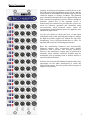
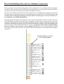
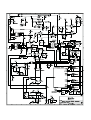
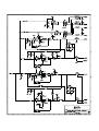
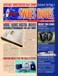
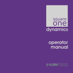
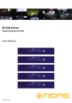
DN1248
OPERATORS MANUAL
Version 2
Klark Teknik Group,
Klark Teknik Building,
Walter Nash Road,
Kidderminster.
Worcestershire.
DY11 7HJ.
England.
Tel:+44 (0) 1562 741515
Fax:+44 (0) 1562 745371
Email: [email protected]
Website: www.klarkteknik.com
Walter Nash Road, Kidderminster, Worcestershire. DY11 7HJ. England
Tel: (44) (0) 1562 741515. Fax: (44) (0) 1562 745371
Company Registration No: 2414018
abc d abc
SI GN A L P R O CE SSI N G BY D E FI N I T I ON
BETTER BY DESIGN
DESIGNED FOR APURE PERFORMANCE
DECLARATION OF CONFORMITY
We, Klark Teknik Group (UK) Plc
of,
Klark Teknik Building, Walter Nash Road, Kidderminster, Worcestershire, DY11 7HJ
Declare that a sample of the following product:Product Type Number
Product Description
Nominal Voltage (s)
DN1248
115V AC
230V AC
Current
130mA
260mA
Freq
50/60Hz
to which this declaration refers, is in conformity with the following directives and/or standards:Directive(s)
Test Standard(s)
Generic Standard Using EN55103 Limits and Methods
Class B Conducted Emissions Pavi
CLass B Radiated Emissions Pavi
Fast Transient Bursts at 2Kv
Static Discharge at 4Kv
Electrical Stress Test
Signed:............................
EN50081/1
EN55103
EN55103
EN61000-4-4
EN61000-4-2
EN60204
Date: 10th December, 1999
Name: David Hoare
Authority: Technical Director, Klark Teknik Group (UK) Plc
Attention!
Where applicable, the attention of the specifier, purchaser, installer or user is drawn to special limitations of use
which must be observed when these products are taken into service to maintain compliance with the above
directives. Details of these special measures and limitations to use are available on request and are available
in product manuals.
A Subsidiary of Telex communications, Inc.
Contents
Thank you for using a Klark Teknik product
After you have unpacked
Introduction
Installation and Connection
Basic operation
Rear panel blanking plate and user mutliple connector
Mic channel
Headphone amp
Applications
Appendices
Specifications
Schematics
Page 1
Page 2
Page 3
Page 4
Page 5
Page 8
Page 9
Page 10
Page 12
Page 13
Page 14
.
Thank
You For Using This Klark Teknik Product
To obtain maximum performance from this precision electronic product, please study these
instructions carefully. Installation and operating the mic splitter is not complicated, but the
flexibility provided by its operating features merits familiarisation with its controls and connections.
This unit has been prepared to comply with the power supply requirements that exist in your
location.
Precautions
Do not install this unit in a location subjected to excessive heat, dust or mechanical vibration.
Voltage Selection and Power Connection
Connection is made by means of an IEC standard power socket. The rear panel text indicates the
voltage range required for satisfactory operation of the unit.
Before connecting this unit to the mains supply, ensure the fuse fitted is the correct type and rating
is as indicated on the rear panel, adjacent to the fuse holder.
Safety Warning
This unit is fitted with 3-pin power socket: For safety reasons the earth lead should not be
disconnected. Signal ground is referenced internally to chassis via a resistor capacitor network
which provides earth loop immunity.
To prevent shock or fire hazard, do not expose the unit to rain or moisture. To avoid electrical shock
do not remove covers. Refer servicing to qualified personnel only.
Attention!
Cables:
This product should only be used with high quality, screened twisted pair audio cables, terminated
with metal bodied 3-pin XLR connectors. The cable should be connected to pin 1. Any other cable
type or configuration for the audio signals may result in degraded performance due to
electromagnetic interference.
Electric Fields:
Should this product be used in an electromagnetic field that is amplitude modulated by an audio
frequency signal (20Hz to 20kHz), the signal to noise ratio may be degraded. Degradation of up to
60dB at a frequency corresponding to the modulation signal may be experienced under extreme
conditions (3V/m, 90% modulation).
1
After You Have Unpacked The Unit
Save all the packing materials - they will prove valuable should it become necessary to transport or
ship this product.
Please inspect this unit carefully for any signs of damage incurred during transportation. It has
undergone stringent quality control inspection and tests prior to packing and left the factory in
perfect condition.
If, however, the unit shows any signs of damage, notify the transportation company without delay.
Only you, the consignee, may institute a claim against the carrier for damage during transportation.
If necessary, contact your supplier or as a last resort, your Klark Teknik importing agent, who will
fully co-operate under such circumstances.
This
Side Up
L abc
2
Introduction
The DN1248 active microphone splitter brings the legendary sound and reliability of Klark Teknik to
this application for the first time. Housed in a rugged 3U rack enclosure, the DN1248 offers a cost and
space-effective method of providing up to forty-eight outputs from twelve sources.
Key Features
!
Midas Heritage Mic pre amp.
!
Inter-unit linkable headphone bus with individual and multiple solo feature.
!
-15dB pad, +30dB boost, earth lift and phantom power switches on all channels.
!
Internal power supply with factory option of backup PSU.
!
Five year international factory warranty.
The Klark Teknik DN1248 is an extremely high performance, 12-channel active mic splitter housed in a
3U, rack mounting case with an integral switch mode power supply that can automatically adapt to
mains voltages in the range 100 to 240 Volts (50 to 60Hz). A dual PSU is available as a factory fitted
option. Applications include splitting on-stage mic and DI box feeds to service monitor and FOH
consoles as well as to facilitate the multitrack recording or broadcasting of live events.
Each microphone input feeds a superbly specified mic preamp based on the circuitry used in the
acclaimed MIDAS Heritage live sound console. There are four balanced outputs per channel, two
transformer isolated and two electronically-balanced.
All the audio connections are on balanced XLRs (wired pin 2 hot) featuring gold plated connectors. The
mic input and three of the four outputs (two transformer and one electronically balanced) are mounted
on the front panel for easy access. The remaining output (electronically balanced) is located on the rear
panel. Signal Present and Clip LEDs are provided for each channel and a solo system allows any
channel or combination of channels to be monitored via the integral headphone amplifier. Two gain
switches (+30dB and -15dB) may be used individually or in combination to optimise the preamplifier
gain. Standard 48 volt phantom powering is individually switchable on each channel. Each mic input is
also fitted with a ground lift switch.
WARNING
48V phantom disabled if ground lift switch selected.
3
Installation And Connection
The Klark Teknik DN1248 is designed for standard 19" rack mounting and occupies 3U of rack space.
Avoid mounting the unit directly above or below power amplifiers or power supplies that radiate
excessive magnetic fields or heat. Ensure that the ventilation apertures on either side of the unit are not
blocked or obstructed.
This unit must be earthed. If ground loop problems are encountered, the ground lift switches on the
microphone inputs may be used. It is also permissible to disconnect the cable screen at one end or other
of the output cables, though the signal input cable screen must be connected at both ends to ensure the
phantom powering operates correctly.
The mains fuse should be rated T0.5L250V .
Outputs 1 and 4 are electronically balanced on conventionally wired XLRs (pin 1 screen, pin 2 hot and
pin 3 return) with a nominal operating level of +4dBu and a maximum output capability of 21dBu.
Transformer coupled outputs 2 and 3 have a maximum signal capability of +18dB. For unbalanced use,
pin 3 of any output XLR may be grounded at the destination end of the cable.
The source impedance of the electronically balanced outputs is 50W while the transformer balanced
outputs have a source impedance of 70W. Both are designed to feed a minimum load of 600W.
4
Basic Operation
Connect all capacitor microphones and DI boxes to the
DN1248 before applying phantom power. Ensure that the
sound system level is turned down at this stage to prevent
switch-on thumps or acoustic feedback. The phantom
power should be switched off for any channel being used
with a dynamic microphone or passive DI box, though no
problems should arise if the phantom power is
inadvertently left switched on, providing the sources are
wired for balanced operation and connected using
conventionally wired balanced cables. Under no
circumstances should phantom power be applied to any
unbalanced input source.
Use the solo facility to check the level of each input
individually and set the gain and pad buttons to achieve
the highest possible signal level without the clip LED
illuminating. Leave sufficient headroom to allow for
unplanned increases in level during performance.
Both the transformer balanced and electronically
balanced outputs offer exceptional audio quality
combined with excellent line driving capability.
However, the transformer outputs may be preferred in
situations where absolute electrical isolation must be
maintained, such as running feeds to mobile studios or
outside broadcast facilities.
In theory, the electronically balanced outputs remove any
opportunity for the audio transformers to colour the
sound, but in practice, the sonic quality of the two types of
outputs is very similar.
5
Out 3 Transformer balanced XLR output.
Out 2 Transformer balanced XLR output.
Out 1 Electronically balanced XLR output.
Input Balanced XLR for microphone level signals.
Out 4 See rear panel
Note:
If either of the transformer balanced outputs ( 2 and 3) is shorted
out, the signal level on the other output may be adversely affected.
The electronically balanced outputs (1 and 4) will remain
unaffected.
Signal Present LED (Green)
An input signal in excess of -25dBu will cause the signal present LED to illuminate.
Signal Clip LED (Red)
An input signal in excess of +21dBu will cause the signal Clip LED to illuminate. The Clip LED
illuminates approximately 0.5dB below the actual clip level.
Solo
Pressing the electronically latching Solo button permits any channel to be monitored in isolation via the
headphone socket on the front of the unit. Each Solo button has an integral status LED and features a
dual mode of operation. When pressed briefly, the solo function will latch on electronically, whereas if
the button is pressed and held, the solo is active only for as long as the button is held down. Pressing the
button again will exit solo mode. Multiple channels may be solo’d. When multiple units are linked, the
solo system permits phones monitoring from any of the linked units.
48V
Applies 48 volt phantom power to the channel's microphone input.
+30dB
Switches in 30dB of mic pre-amp gain.
-15dB
Switches in a 15dB attenuator pad. (Note that both switches may be used together when a gain of 15dB
is required.)
Lift
Isolates the input signal ground. Note: Switching in the ground lift disables phantom power operation.
The Lift switch has an integral red status LED.
6
Channels 1 to 12
Out 4
Electronically balanced XLR output located on the
rear panel. All four outputs produce nominally the
same signal level.
Blanking plate
Dimensions of the plate: 158mm x 88mm
Internal dimensions:140mm x 70mm
Solo Bus Connectors
These are standard 3-pin male and female XLR sockets
enabling the solo systems of two or more DN1248s to
be linked by means of standard microphone cables.
When linked, the units act as a single unit for solo
monitoring purposes with the solo’d output being
available on the phones outputs of any linked units
Mains Inlet
Standard non-switched IEC mains connector. A
suitable cable is provided.
7
Rear Panel Blanking Plate and User Multipole Connections
The rear panel has a removable blanking plate which is designed for users to fit their choice of multipole
connectors. The circuit board for each for the twelve channels has a row of spring-leaf terminals along its
rear edge to allow users to terminate cables from the mutipole connectors.
The top cover should be removed from the unit to gain access to the blanking plate and the circuit board
terminals. Please ensure that all screws are retained and used to re-attach the cover and blanking plate. Any
warranty claims resulting from damage to the unit will be void if all of the screws are not used to resecure both the cover and the blanking plate.
The input and all four outputs are brought out to the circuit board terminals; to make a connection insert a
small flat-bladed screwdriver into the upper rectangular slot and using a levering motion, move the
screwdriver away from the circuit board - this action will open the contacts in the lower opening in the
connector so that the bare ends of a wire can be inserted. Moving the screwdriver in the other direction will
close the contacts, which will then hold the wire securely. Any warranty claims will be void if the damage
has been caused by excessive force to these multipole connectors. It is recommended that screened
twisted pair cable is used to make the connections between the individual circuit boards and the multipole
connectors.
Cold (XLR pin 3)
Hot (XLR pin 2)
OUT 1 OUT 2 OUT 3
Insert flat bladed-screw driver
here to open multipole
Ground (XLR pin 1)
Cold (XLR pin 3)
Hot (XLR pin 2)
Ground (XLR pin 1)
Cold (XLR pin 3)
Hot (XLR pin 2)
Ground (XLR pin 1)
Hot (XLR pin 2)
IN
Cold (XLR pin 3)
Cold (XLR pin 3)
Hot (XLR pin 2)
OUT 4
Ground (XLR pin 1)
Ground (XLR pin 1)
Mic Channel
The mic input is based around the same circuitry as used in the Midas Heritage live sound console and
features exceptionally low noise and distortion combined with a generous level of headroom. The mic
preamp gain may be adjusted by using the -15dB pad and +30dB boost switches either singly or in
combination. With neither selected, the signal path is unity gain. The gain range is adequate to
accommodate most microphones, keyboards, DI boxes, backline preamp outputs and active
guitar/basses. Passive guitars require a high impedance load and should be connected via a suitable
active DI box, such as the Klark Teknik LBB100 or DN1414.
9
Headphone Amp
Illuminated Logo
The DN1248 has no mains power switch. When power
is connected, the logo at the front right of the panel will
illuminate.
Phones Level
Sets the level of the headphone output used for Solo
monitoring.
Meter
Seven segment LED meter monitors the level of any
soloed signal in the range -40 (Sig) to 0dB. The
metering may be used in conjunction with the input gain
switches and the solo buttons to optimise the input gain
settings.
Phones
Standard quarter inch TRS jack to accept
conventionally wired stereo headphones. Any soloed
channel or channels will appear at the headphone output
under control of the Phones Volume control.
Solo Bus Operation
Pressing the electronically latching Solo
button permits any channel to be monitored
in isolation via the headphone socket on the
front of the unit. Each Solo button has an
integral status LED and features a dual mode
of operation. When pressed briefly, the solo
function will latch on electronically, whereas
if the button is pressed and held, the solo is
active only for as long as the button is held
down. A channel which has been
electronically latched can be cleared by
briefly pressing in the same manner. The
electronic latching function allows multiple
channels to be switched onto the Solo bus.
The Solo bus external linking facility allows
solo’d channels to be monitored using the
headphone amp on any of the connected
units. Note: The Solo bus bargraph on each
connected unit only displays the signal level
for that unit, which has the advantage of
making it easier to isolate level or connection
problems. Multiple units are connected Solo
Out to Solo In as shown left.
10
Applications
In a live recording situation, the DN1248 may be used either to split the stage mic signals at source or to
take feeds from the group outputs of a live sound console. It is also able to accommodate feeds from
backline preamp outputs, active instruments, keyboards and so on. Because there are four outputs per
channel, it is possible to interpose the unit between an instrument and its backline amplification while
still providing up to three feeds for mixing, monitoring or recording. A number of examples are
illustrated below.
Example 1 Shows an outside broadcast application where the DN1248 supplies feeds to both the FOH
live sound console and a monitor console as well as to two outside broadcast/recording trucks.
Normally the transformer balanced outputs (2 and 3) would be used to feed the OB trucks.
Example 2 Shows a simple live recording situation where the stage mic feeds are split to serve the FOH
live sound console, a monitor console and an on-site recording console. It is recommended that one of
the transformer balanced outputs is used to feed the recording console, especially if the grounding
scheme is outside the control of the PAoperator.
11
Example 3 Shows a live recording application where the DN1248 is used to provide isolated feeds from
the group outputs of the FOH live sound console.
12
Appendices
Architect’s and Engineer’s Specification
The Mic Splitter shall provide 12 discrete audio channels in a standard 3U 19" rack mount chassis. Each
channel shall have a microphone preamplifier, two transformer-isolated outputs, and two electronically
balanced outputs with two paralleled connectors. Both transformer - isolated outputs and one
electronically balanced output will be mounted on the front panel, the remaining electronically
balanced output will be mounted on the back panel.
Each channel shall also provide separate +30dB boost and -15 dB pad switches, switchable +48V
phantom power, an earth lift function and a soloing facility.
The Mic Splitter shall have a headphone amp to allow the monitoring of soloed audio channels. The
headphone amplifier shall have a ¼ -inch jack socket for the headphones, a rotary level control for the
headphones output and a seven-segment LED bargraph for monitoring the soloed signal level.
Each Mic Splitter shall meet or exceed the following performance specifications:
Electronically Balanced Outputs
Distortion
Frequency response
< 0.01% (1kHz @ +4dBu)
+0/-0.5dB (20Hz to 20 kHz)
Transformer Balanced Outputs
Distortion
Frequency response
<0.01% (1kHz @ +4dBu)
+0/-1.0dB (20Hz to 20kHz)
The audio connections for each of the twelve audio channels shall be via 3-pin XLR style connectors
one female connector for the input and four male connectors for the outputs.
The unit shall be capable of operating from a 90 to 250V, 50 to 60Hz AC power source. The unit should
have the option of dual redundant power supplies.
The Mic Splitter shall be the Klark Teknik model DN1248 and no alternative option is available.
13
Specifications
Inputs
Input impedance
CMRR
Equivalent input noise
Connectors
Signal present level
Signal clip level
> 2kW
> -100dB @ 100Hz to 10kHz
< - 100dBu @ unity gain
3 pin male XLR
> - 25dBu
> + 21dBu
Outputs
Electronically balanced
Source impedance
Min Load
Max level
Connectors
50W
600W
+ 21dBu @ 1kHz
3 pin female XLR
Transformer balanced & isolated
Source impedance
Min Load
Max level
Connectors
70W
600W (-3dB level loss into 200W )
+ 18dBu @ 1kHz
3 pin female XLR
Performance
Electronically balanced
Frequency response
Distortion
+ 0 / - 0.5dB 20Hz to 20kHz
< 0.01 % @ 1kHz +4dB
Transformer balanced & isolated
Frequency response
Distortion
+ 0 / -3.0dB 20Hz to 20kHz
< 0.05 % @ 1kHz +4dB
Power Requirements
90 to 250V a.c @ 50/60Hz @ < 75VA
3 pin IEC connector.
Dimensions
Width
Height
Depth
483 mm (19 inches)
132 mm (5.2 inches)
300 mm (12 inches)
Weights
Nett
Shipping
7.4 kg
8.4 kg
14
Klark Teknik reserve the right to alter these specifications without prior notice.
Schematic Drawings
DN1248
Mic Splitter Headphones
Mic Splitter Channel Schematic 1
Mic Splitter Channel Schematic 2
Mic Splitter Channel Schematic 3