1
37527
LS-5 Series
Circuit Breaker Control
User Manual
Software Version 1.xxxx
Manual 37527
Manual 37527
LS-5 Series - Circuit Breaker Control
WARNING
Read this entire manual and all other publications pertaining to the work to be performed before installing, operating, or servicing this equipment. Practice all plant and safety instructions and precautions.
Failure to follow instructions can cause personal injury and/or property damage.
The engine, turbine, or other type of prime mover should be equipped with an overspeed (overtemperature, or overpressure, where applicable) shutdown device(s), that operates totally independently of the
prime mover control device(s) to protect against runaway or damage to the engine, turbine, or other
type of prime mover with possible personal injury or loss of life should the mechanical-hydraulic governor(s) or electric control(s), the actuator(s), fuel control(s), the driving mechanism(s), the linkage(s),
or the controlled device(s) fail.
Any unauthorized modifications to or use of this equipment outside its specified mechanical, electrical,
or other operating limits may cause personal injury and/or property damage, including damage to the
equipment. Any such unauthorized modifications: (i) constitute "misuse" and/or "negligence" within
the meaning of the product warranty thereby excluding warranty coverage for any resulting damage,
and (ii) invalidate product certifications or listings.
CAUTION
To prevent damage to a control system that uses an alternator or battery-charging device, make sure
the charging device is turned off before disconnecting the battery from the system.
Electronic controls contain static-sensitive parts. Observe the following precautions to prevent damage to these parts.
•
Discharge body static before handling the control (with power to the control turned off, contact a
grounded surface and maintain contact while handling the control).
•
Avoid all plastic, vinyl, and Styrofoam (except antistatic versions) around printed circuit boards.
•
Do not touch the components or conductors on a printed circuit board with your hands or with
conductive devices.
OUT-OF-DATE PUBLICATION
This publication may have been revised or updated since this copy was produced. To verify that you
have the latest revision, be sure to check the Woodward website:
http://www.woodward.com/pubs/current.pdf
The revision level is shown at the bottom of the front cover after the publication number. The latest
version of most publications is available at:
http://www.woodward.com/publications
If your publication is not there, please contact your customer service representative to get the latest
copy.
Important definitions
WARNING
Indicates a potentially hazardous situation that, if not avoided, could result in death or serious injury.
CAUTION
Indicates a potentially hazardous situation that, if not avoided, could result in damage to equipment.
NOTE
Provides other helpful information that does not fall under the warning or caution categories.
Woodward reserves the right to update any portion of this publication at any time. Information provided by Woodward is believed to be
correct and reliable. However, Woodward assumes no responsibility unless otherwise expressly undertaken.
© Woodward
All Rights Reserved.
Page 2/275
© Woodward
Manual 37527
LS-5 Series - Circuit Breaker Control
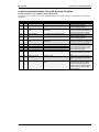
Revision History
Rev. Date
NEW 11-02-28
Editor Changes
TE
Release
Content
CHAPTER 1. GENERAL INFORMATION ..................................................................................... 10
Document Overview ............................................................................................................................... 10
CHAPTER 2. INSTALLATION .................................................................................................... 11
Electrostatic Discharge Awareness ....................................................................................................... 11
Marine Usage (Pending) ........................................................................................................................ 12
Application ................................................................................................................................... 12
Housing Types ....................................................................................................................................... 13
Plastic Housing ............................................................................................................................ 14
Sheet Metal Housing.................................................................................................................... 18
Wiring Diagrams ..................................................................................................................................... 19
Connections ........................................................................................................................................... 20
Power Supply ......................................................................................................................................... 21
Voltage Measuring ................................................................................................................................. 22
Voltage Measuring: System A ..................................................................................................... 22
Voltage Measuring: System B ..................................................................................................... 28
Current Measuring ................................................................................................................................. 34
System A Current......................................................................................................................... 34
Power Measuring ................................................................................................................................... 36
Power Factor Definition .......................................................................................................................... 36
Discrete Inputs ....................................................................................................................................... 38
Discrete Inputs: Signal Polarity .................................................................................................... 38
Discrete Inputs: Operation Logic ................................................................................................. 39
Relay Outputs (LogicsManager) ............................................................................................................ 40
Interfaces................................................................................................................................................ 42
RS-485 Serial Interface................................................................................................................ 42
Service Port (RS-232) .................................................................................................................. 42
CAN Bus Interface ....................................................................................................................... 43
Bus Shielding ............................................................................................................................... 45
DPC - Direct Configuration Cable ................................................................................................ 46
CHAPTER 3. CONFIGURATION ................................................................................................ 47
Configuration Via Front Panel ................................................................................................................ 47
Configuration Via PC .............................................................................................................................. 48
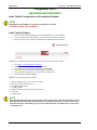
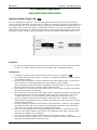
Install ToolKit Configuration and Visualization Software ............................................................. 48
Install ToolKit Software ................................................................................................................ 48
Install ToolKit Configuration Files ................................................................................................ 49
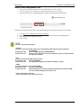
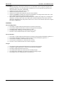
Starting ToolKit Software ............................................................................................................. 50
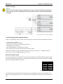
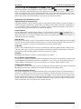
Configure ToolKit Software .......................................................................................................... 51
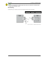
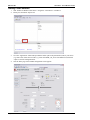
Connect ToolKit and the LS-5 Unit .............................................................................................. 52
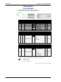
View LS-5 Data with ToolKit ........................................................................................................ 54
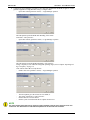
Configure the LS-5 with ToolKit ................................................................................................... 55
© Woodward
Page 3/275
Manual 37527
LS-5 Series - Circuit Breaker Control
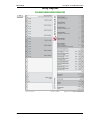
Parameters ............................................................................................................................................ 56
Language / Clock Configuration .................................................................................................. 56
Display Configuration .................................................................................................................. 58
Enter Password ........................................................................................................................... 59
System Management................................................................................................................... 60
System Management: Password System ................................................................................... 61
Configuration ............................................................................................................................... 62
CHAPTER 4. OPERATION ...................................................................................................... 118
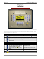
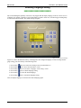
Screen Structure .................................................................................................................................. 121
Navigation ............................................................................................................................................ 122
Alarm List ................................................................................................................................... 122
Parameter .................................................................................................................................. 122
Main Menu ................................................................................................................................. 124
Display Messages ................................................................................................................................ 129
Status Messages ....................................................................................................................... 129
Alarm Messages ........................................................................................................................ 130
Restoring Language Setting ................................................................................................................ 132
LS-51x (ToolKit) ................................................................................................................................... 133
Special ToolKit Screens ............................................................................................................ 134
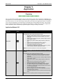
CHAPTER 5. APPLICATION ................................................................................................... 136
Overview .............................................................................................................................................. 136
Application Modes LS-5 ............................................................................................................ 136
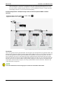
Application Modes easYgen-3400/3500 Interacting With LS-5 ................................................. 138
Correlation Application Modes easYgen3500/3400 And LS-5 .................................................. 143
LS-5 Standalone Application ............................................................................................................... 144
Application Mode: Single LS5 |
........................................................................................ 144
LS-5 Series & easYgen-3400/500 Applications .................................................................................. 145
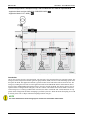
General ...................................................................................................................................... 145
The LS-5 Runs As A Slave Unit (Mode “L-MCB”
; Mode “L-GGB”
) ......................... 146
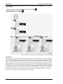
The LS-5 runs as independent unit (Mode “LS5”
)............................................................ 155
CHAPTER 6. INTERFACE ....................................................................................................... 179
Interfaces Overview ............................................................................................................................. 179
CAN Interface ............................................................................................................................ 180
Serial Interfaces......................................................................................................................... 181
Protocols Overview .............................................................................................................................. 182
CANopen ................................................................................................................................... 182
Modbus ...................................................................................................................................... 184
CHAPTER 7. TECHNICAL DATA ............................................................................................. 187
Environmental Data ............................................................................................................................. 190
Accuracy .............................................................................................................................................. 191
APPENDIX A. USEFUL INFORMATION ..................................................................................... 192
Connecting 24 V Relays ...................................................................................................................... 192
APPENDIX B. MISCELLANEOUS ............................................................................................ 194
Alarm Classes ...................................................................................................................................... 194
Page 4/275
© Woodward
Manual 37527
LS-5 Series - Circuit Breaker Control
APPENDIX C. LOGICSMANAGER ........................................................................................... 195
Logical Symbols ................................................................................................................................... 196
Logical Outputs .................................................................................................................................... 197
Logical Outputs: Internal Flags .................................................................................................. 197
Logical Outputs: LS-5 Flags ...................................................................................................... 197
Logical Outputs: Internal Functions ........................................................................................... 198
Logical Outputs: Relay Outputs ................................................................................................. 199
Logical Command Variables ................................................................................................................ 200
Logical Command Variables: Group 00: Flags Condition 1....................................................... 201
Logical Command Variables: Group 01: Alarm System ............................................................ 202
Logical Command Variables: Group 02: Systems Condition..................................................... 203
Logical Command Variables: Group 04: Applications Condition ............................................... 204
Logical Command Variables: Group 05: Device Related Alarms .............................................. 205
Logical Command Variables: Group 06: System B Related Alarms ......................................... 205
Logical Command Variables: Group 07: System A Related Alarms ......................................... 205
Logical Command Variables: Group 08: System Related Alarms ............................................. 205
Logical Command Variables: Group 09: Discrete Inputs........................................................... 206
Logical Command Variables: Group 11: Clock and Timer ........................................................ 206
Logical Command Variables: Group 13: Discrete Outputs ........................................................ 206
Logical Command Variables: Group 24: Flags condition 2 ....................................................... 207
Logical Command Variables: Group 26: Flags of LS5 (33 to 48) .............................................. 207
Logical Command Variables: Group 27: Flags of LS5 (49 to 64) .............................................. 209
Logical Command Variables: Group 28: LS5 system conditions .............................................. 210
Logical Command Variables: Group 29: Commands of EG (1 to 16) ....................................... 210
Logical Command Variables: Group 30: Commands of EG (17 to 32) ..................................... 212
Factory Setting ..................................................................................................................................... 214
APPENDIX D. DATA PROTOCOLS .......................................................................................... 218
Modbus ...................................................................................................................................... 218
CAN Bus .................................................................................................................................... 242
APPENDIX E. EVENT HISTORY .............................................................................................. 255
Resetting the Event History ....................................................................................................... 255
APPENDIX F. PARAMETER LIST ............................................................................................ 257
Introduction........................................................................................................................................... 257
Parameter List Columns ............................................................................................................ 257
Parameter............................................................................................................................................. 258
APPENDIX G. SERVICE OPTIONS .......................................................................................... 270
Product Service Options ...................................................................................................................... 270
Returning Equipment For Repair ......................................................................................................... 270
Packing A Control ...................................................................................................................... 271
Return Authorization Number RAN ............................................................................................ 271
Replacement Parts ............................................................................................................................... 271
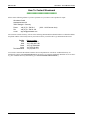
How To Contact Woodward ................................................................................................................. 272
Engineering Services ........................................................................................................................... 273
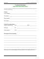
Technical Assistance ........................................................................................................................... 274
© Woodward
Page 5/275
Manual 37527
LS-5 Series - Circuit Breaker Control
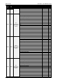
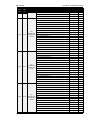
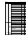
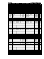
Figures and Tables
Figures
Figure 2-1: Housing - panel-board cutout ................................................................................................................................. 14
Figure 2-2: Plastic housing LS-521 – dimensions..................................................................................................................... 15
Figure 2-3: Plastic housing - drill plan ...................................................................................................................................... 17
Figure 2-4: Sheet metal housing LS-511 – dimensions............................................................................................................. 18
Figure 2-5: Sheet metal housing - drill plan .............................................................................................................................. 18
Figure 2-6: LS-5 Series – wiring diagram ................................................................................................................................. 19
Figure 2-7: Power supply .......................................................................................................................................................... 21
Figure 2-8: Power supply - crank waveform at maximum load ................................................................................................ 21
Figure 2-9: Voltage measuring – system A ............................................................................................................................... 22
Figure 2-10: Voltage measuring – system A windings, 3Ph 4W .............................................................................................. 23
Figure 2-11: Voltage measuring – system A measuring inputs, 3Ph 4W .................................................................................. 23
Figure 2-12: Voltage measuring – system A windings, 3Ph 3W .............................................................................................. 24
Figure 2-13: Voltage measuring – system A measuring inputs, 3Ph 3W .................................................................................. 24
Figure 2-14: Voltage measuring – system A windings, 1Ph 3W .............................................................................................. 25
Figure 2-15: Voltage measuring – system A measuring inputs, 1Ph 3W .................................................................................. 25
Figure 2-16: Voltage measuring – system A windings, 1Ph 2W (phase-neutral)...................................................................... 26
Figure 2-17: Voltage measuring – system A measuring inputs, 1Ph 2W (phase-neutral) ......................................................... 26
Figure 2-18: Voltage measuring – system A windings, 1Ph 2W (phase-phase)........................................................................ 27
Figure 2-19: Voltage measuring – system A measuring inputs, 1Ph 2W (phase-phase) ........................................................... 27
Figure 2-20: Voltage measuring – system B ............................................................................................................................. 28
Figure 2-21: Voltage measuring – system B PT windings, 3Ph 4W ......................................................................................... 29
Figure 2-22: Voltage measuring – system B measuring inputs, 3Ph 4W .................................................................................. 29
Figure 2-23: Voltage measuring – system B PT windings, 3Ph 3W ......................................................................................... 30
Figure 2-24: Voltage measuring – system B measuring inputs, 3Ph 3W .................................................................................. 30
Figure 2-25: Voltage measuring – system B PT windings, 1Ph 3W ......................................................................................... 31
Figure 2-26: Voltage measuring - mains system B measuring inputs, 1Ph 3W ........................................................................ 31
Figure 2-27: Voltage measuring – system B PT windings, 1Ph 2W (phase-neutral) ................................................................ 32
Figure 2-28: Voltage measuring – system B measuring inputs, 1Ph 2W (phase-neutral) ......................................................... 32
Figure 2-29: Voltage measuring – system B PT windings, 1Ph 2W (phase-phase) .................................................................. 33
Figure 2-30: Voltage measuring – system B measuring inputs, 1Ph 2W (phase-phase) ........................................................... 33
Figure 2-31: Current measuring – System A............................................................................................................................. 34
Figure 2-32: Current measuring – system A, L1 L2 L3 ............................................................................................................ 35
Figure 2-33: Current measuring – system A, phase Lx ............................................................................................................. 35
Figure 2-34: Power measuring - direction of power ................................................................................................................. 36
Figure 2-35: Discrete inputs - alarm/control input - positive signal .......................................................................................... 38
Figure 2-36: Discrete inputs - alarm/control input - negative signal ......................................................................................... 38
Figure 2-37: Discrete inputs - alarm/control inputs - operation logic ....................................................................................... 39
Figure 2-38: Relay outputs........................................................................................................................................................ 40
Figure 2-39: RS-485 - connection for half-duplex operation .................................................................................................... 42
Figure 2-40: RS-232 interface - overview................................................................................................................................. 42
Figure 2-41: Interfaces - CAN bus - termination ...................................................................................................................... 44
Figure 2-42: Interfaces – shielding (external RC element) ....................................................................................................... 45
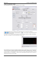
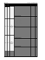
Figure 3-1: ToolKit - visualization screen ................................................................................................................................ 54
Figure 3-2: ToolKit - analog value trending screen .................................................................................................................. 54
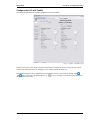
Figure 3-3: ToolKit - configuration screen ............................................................................................................................... 55
Figure 3-4: Monitoring - phase shift ......................................................................................................................................... 84
Figure 3-5: Interfaces - Principle of RPDO mapping .............................................................................................................. 107
Figure 3-6: Interfaces - Principle of TPDO mapping .............................................................................................................. 108
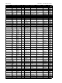
Figure 4-1: Front panel and display ........................................................................................................................................ 118
Figure 4-2: Screen structure .................................................................................................................................................... 121
Figure 4-3: Front panel and display ........................................................................................................................................ 132
Figure 4-4: LS-51x – front panel ............................................................................................................................................ 133
Figure 4-5: ToolKit screen – states easYgen........................................................................................................................... 134
Figure 4-6: ToolKit screen – states LS-5 ................................................................................................................................ 135
Figure 5-1: Application mode – Single LS5 ........................................................................................................................... 144
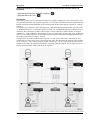
Figure 5-2: Single or multiple easYgen with one external operated MCB.............................................................................. 146
Figure 5-3: Multiple easYgen with one GGB and one external operated MCB ...................................................................... 148
Figure 5-4: Multiple easYgen with one external operated GGB in isolated operation ............................................................ 150
Figure 5-5: Multiple easYgen with one external operated GGB and one external operated MCB.......................................... 152
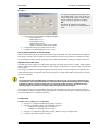
Figure 5-6: Example ToolKit: Configure AMF start segments by clicking on the segment number ...................................... 158
Page 6/275
© Woodward
Manual 37527
LS-5 Series - Circuit Breaker Control
Figure 5-7: LogicsManager system - easYgen information transport to LS-5 ........................................................................ 159
Figure 5-8: LogicsManager system – LS-5 information transport to LS-5 and easYgen ........................................................ 160
Figure 5-9: Application – H-Configuration with two easYgen and two incoming mains and tie-breaker .............................. 161
Figure 5-10: Application – Multiple Mains/Generator with two easYgen and two incoming mains and different tie-breaker 168
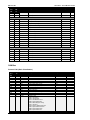
Figure 6-1: Interface ovierview ............................................................................................................................................... 179
Figure 6-2: CAN interface 1 ................................................................................................................................................... 180
Figure 6-3: RS-232 interface ................................................................................................................................................... 181
Figure 6-4: RS-485 interface ................................................................................................................................................... 181
Figure 6-5: Visualization configurations................................................................................................................................. 185
Figure 7-1: Interference suppressing circuit - connection ....................................................................................................... 192
Figure 7-2: LogicsManager - function overview .................................................................................................................... 195
Figure 7-3: LogicsManager - display in ToolKit .................................................................................................................... 196
Figure 7-4: LogicsManager - display on LCD screen ............................................................................................................. 196
© Woodward
Page 7/275
Manual 37527
LS-5 Series - Circuit Breaker Control
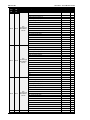
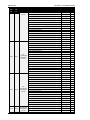
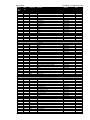
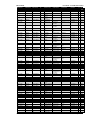
Tables
Table 1-1: Manual - overview ................................................................................................................................................... 10
Table 2-1: Plastic housing - panel cutout .................................................................................................................................. 14
Table 2-2: Conversion chart - wire size .................................................................................................................................... 20
Table 2-3: Power supply - terminal assignment ........................................................................................................................ 21
Table 2-4: Voltage measuring - terminal assignment – system A voltage ................................................................................ 22
Table 2-5: Voltage measuring - terminal assignment – system A, 3Ph 4W .............................................................................. 23
Table 2-6: Voltage measuring - terminal assignment – system A, 3Ph 3W .............................................................................. 24
Table 2-7: Voltage measuring - terminal assignment – system A, 1Ph 3W .............................................................................. 25
Table 2-8: Voltage measuring - terminal assignment – system A, 1Ph 2W (phase-neutral) ..................................................... 26
Table 2-9: Voltage measuring - terminal assignment – system A, 1Ph 2W (phase-phase) ....................................................... 27
Table 2-10: Voltage measuring - terminal assignment – system B voltage .............................................................................. 28
Table 2-11: Voltage measuring - terminal assignment – system B, 3Ph 4W ............................................................................ 29
Table 2-12: Voltage measuring - terminal assignment – system B, 3Ph 3W ............................................................................ 30
Table 2-13: Voltage measuring - terminal assignment – system B, 1Ph 3W ............................................................................ 31
Table 2-14: Voltage measuring - terminal assignment – system B, 1Ph 2W (phase-neutral) ................................................... 32
Table 2-15: Voltage measuring - terminal assignment – system B, 1Ph 2W (phase-phase) ..................................................... 33
Table 2-16: Current measuring - terminal assignment – system A current ............................................................................... 34
Table 2-17: Current measuring - terminal assignment – system A, L1 L2 L3 .......................................................................... 35
Table 2-18: Current measuring - terminal assignment – system A, phase Lx ........................................................................... 35
Table 2-19: Power measuring - terminal assignment ................................................................................................................ 36
Table 2-20: Discrete input - terminal assignment ..................................................................................................................... 38
Table 2-21: Relay outputs - terminal assignment ...................................................................................................................... 40
Table 2-22: RS-485 interface - pin assignment ......................................................................................................................... 42
Table 2-23: RS-232 interface (DPC) - pin assignment.............................................................................................................. 42
Table 2-24: CAN bus - pin assignment ..................................................................................................................................... 43
Table 2-25: Maximum CAN bus length .................................................................................................................................... 44
Table 2-26: Bus shielding ......................................................................................................................................................... 45
Table 3-1: Daylight saving time - configuration example ......................................................................................................... 58
Table 3-2: Daylight saving time - examplary dates................................................................................................................... 58
Table 3-3: Calculation of the phase angle deviation ................................................................................................................. 69
Table 3-4: Discrete inputs - parameter IDs ............................................................................................................................... 74
Table 3-5: Relay outputs - assignment ...................................................................................................................................... 75
Table 3-6: Discrete outputs - parameter IDs ............................................................................................................................. 75
Table 3-7: Internal flags - parameter IDs ................................................................................................................................ 113
Table 3-8: LS5 flags - parameter IDs ...................................................................................................................................... 113
Table 3-9: LED flags - parameter IDs ..................................................................................................................................... 114
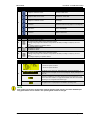
Table 4-1: Measuring values ................................................................................................................................................... 120
Table 4-2: Message IDs for discrete inputs ............................................................................................................................. 131
Table 4-3: Icons – states easYgen ........................................................................................................................................... 134
Table 4-4: Icons – states LS-5................................................................................................................................................. 135
Table 6-1: Transfer syntax for data type UNSIGNEDn .......................................................................................................... 183
Table 6-2: Transfer syntax for data type INTEGERn ............................................................................................................. 183
Table 6-3: Address range ........................................................................................................................................................ 184
Table 6-4: Address range block read ...................................................................................................................................... 185
Table 6-5: Address calculation ............................................................................................................................................... 186
Table 6-6: Data types .............................................................................................................................................................. 186
Table 7-1: Interference suppressing circuit for relays ............................................................................................................. 193
Table 7-2: LogicsManager - command overview ................................................................................................................... 195
Table 7-3: LogicsManager - logical symbols.......................................................................................................................... 196
Table 7-4: Relay outputs - terminal assignment ...................................................................................................................... 199
Table 7-5: Load share message - example .............................................................................................................................. 251
Table 7-6: Load share line - max. length (32 participants) ..................................................................................................... 251
Table 7-7: Load share line - max. length (48 participants) ..................................................................................................... 252
Table 7-8: Event history - event list ........................................................................................................................................ 255
Page 8/275
© Woodward
Manual 37527
LS-5 Series - Circuit Breaker Control
Glossary And List Of Abbreviations
CB
CL
CT
DI
DO
ECU
FMI
GCB
I
IOP
LDSS
MCB
MOP
MPU
N.C.
N.O.
OC
P
P/N
PF
PF
PID
PLC
PT
Q
S
S/N
SPN
V
© Woodward
Circuit Breaker
Code Level
Current Transformer
Discrete Input
Discrete (Relay) Output
Engine Control Unit
Failure Mode Indicator
Generator Circuit Breaker
Current
Isolated Operation in Parallel
Load-Dependent Start/Stop operation
Mains Circuit Breaker
Mains Operation in Parallel
Magnetic Pickup Unit
Normally Closed (break) contact
Normally Open (make) contact
Occurrence Count
Real power
Part Number
Power Factor
Power factor
Proportional Integral Derivative controller
Programmable Logic Control
Potential (Voltage) Transformer
Reactive power
Apparent power
Serial Number
Suspect Parameter Number
Voltage
Page 9/275
Manual 37527
LS-5 Series - Circuit Breaker Control
Chapter 1.
General Information
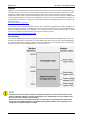
Document Overview
≡≡≡≡≡≡≡≡≡≡≡≡≡≡≡≡≡≡≡≡≡≡≡≡≡
This manual describes the LS-5 Series circuit breaker control.
Type
LS-5
LS-5 Series – User Manual
easYgen-3400/3500 – User Manual
this manual
English
German
37527
37528
-
Table 1-1: Manual - overview
Intended Use The unit must only be operated in the manner described by this manual. The prerequisite for a
proper and safe operation of the product is correct transportation, storage, and installation as well as careful operation and maintenance.
NOTE
This manual has been developed for a unit fitted with all available options. Inputs/outputs, functions,
configuration screens, and other details described, which do not exist on your unit, may be ignored.
The present manual has been prepared to enable the installation and commissioning of the unit. Due to
the large variety of parameter settings, it is not possible to cover every combination. The manual is
therefore only a guide. In case of incorrect entries or a total loss of functions, the default settings may
be taken from the Parameter List which can be found in the appendix or from ToolKit and the respective *.SID file.
Page 10/275
© Woodward
Manual 37527
LS-5 Series - Circuit Breaker Control
Chapter 2.
Installation
Electrostatic Discharge Awareness
≡≡≡≡≡≡≡≡≡≡≡≡≡≡≡≡≡≡≡≡≡≡≡≡≡
All electronic equipment is static-sensitive, some components more than others. To protect these components
from static damage, you must take special precautions to minimize or eliminate electrostatic discharges.
Follow these precautions when working with or near the control.
1.
Before doing maintenance on the electronic control, discharge the static electricity on your body to ground
by touching and holding a grounded metal object (pipes, cabinets, equipment, etc.).
2.
Avoid the build-up of static electricity on your body by not wearing clothing made of synthetic materials.
Wear cotton or cotton-blend materials as much as possible because these do not store static electric
charges as easily as synthetics.
3.
Keep plastic, vinyl, and Styrofoam materials (such as plastic or Styrofoam cups, cigarette packages, cellophane wrappers, vinyl books or folders, plastic bottles, etc.) away from the control, modules, and work
area as much as possible.
4.
Opening the control cover may void the unit warranty.
Do not remove the printed circuit board (PCB) from the control cabinet unless absolutely necessary. If you
must remove the PCB from the control cabinet, follow these precautions:
• Ensure that the device is completely voltage-free (all connectors have to be disconnected).
• Do not touch any part of the PCB except the edges.
• Do not touch the electrical conductors, connectors, or components with conductive devices or with
bare hands.
• When replacing a PCB, keep the new PCB in the plastic antistatic protective bag it comes in until you
are ready to install it. Immediately after removing the old PCB from the control cabinet, place it in the
antistatic protective bag.
CAUTION
To prevent damage to electronic components caused by improper handling, read and observe the precautions in Woodward manual 82715, Guide for Handling and Protection of Electronic Controls, Printed
Circuit Boards, and Modules.
© Woodward
Page 11/275
Manual 37527
LS-5 Series - Circuit Breaker Control
Marine Usage (Pending)
≡≡≡≡≡≡≡≡≡≡≡≡≡≡≡≡≡≡≡≡≡≡≡≡≡
CAUTION
The following notes are very important for marine usage of the LS-5 circuit breaker control and have to
be followed.
Application
The LS-5 Series has no internally isolated power supply.
For marine applications an EMI filter (i.e. SCHAFFNER - FN 2070-3-06) must be connected ahead of the power
supply input.
To meet the functional safety requirements of the application, the rules of marine classification independent protective devices must be applied.
Page 12/275
© Woodward
Manual 37527
LS-5 Series - Circuit Breaker Control
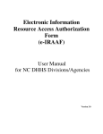
Housing Types
≡≡≡≡≡≡≡≡≡≡≡≡≡≡≡≡≡≡≡≡≡≡≡≡≡
The controls of the LS-5 Series are available with two different housing types.
LS-511 - Sheet metal housing. Back panel mounting.
© Woodward
LS-521 - Plastic housing with LCD display. Front
panel mounting.
Page 13/275
Manual 37527
LS-5 Series - Circuit Breaker Control
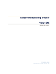
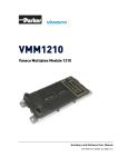
Plastic Housing
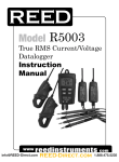
Panel Cutout
Figure 2-1: Housing - panel-board cutout
Measure
H
h
h'
W
w
w'
Description
Height
Width
Depth
Total
Panel cutout
Housing dimension
Total
Panel cutout
Housing dimension
Total
171 mm
138 mm
136 mm
219 mm
186 mm
184 mm
61 mm
Tolerance
--+ 1.0 mm
--+ 1.1 mm
---
Table 2-1: Plastic housing - panel cutout
The maximum permissible corner radius is 3.5 mm.
Refer to Figure 2-3 on page 17 for a cutout drawing.
Page 14/275
© Woodward
Manual 37527
LS-5 Series - Circuit Breaker Control
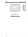
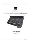
Dimensions
Figure 2-2: Plastic housing LS-521 – dimensions
© Woodward
Page 15/275
Manual 37527
LS-5 Series - Circuit Breaker Control
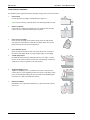
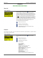
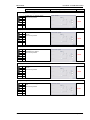
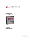
Clamp Fastener Installation
For installation into a panel door with the fastening clamps, please proceed as follows:
1.
Panel cutout
Cut out the panel according to the dimensions in Figure 2-1.
Note: It is not necessary to drill the holes if the fastening clamps are used.
2.
Remove terminals
Loosen the wire connection terminal screws on the back of the unit and
remove the wire connection terminal strip if required.
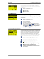
3.
Insert screws in clamps
Insert the four clamping screws into the clamp inserts from the shown
side (opposite of the nut insert) until they are almost flush. Do not completely insert the screws into the clamp inserts.
4.
Insert unit into cutout
Insert the unit into the panel cutout. Verify that the unit fits correctly in
the cutout. If the panel cutout is not big enough, enlarge it accordingly.
5.
Attach clamp inserts
Re-install the clamp inserts by tilting the insert to a 45° angle. (1) Insert
the nose of the insert into the slot on the side of the housing. (2) Raise the
clamp insert so that it is parallel to the control panel.
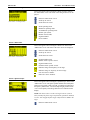
6.
Tighten clamping screws
Tighten the clamping screws (1) until the control unit is secured to the
control panel (2). Over tightening of these screws may result in the clamp
inserts or the housing breaking. Do not exceed the recommended tightening torque of 0.1 Nm (0.9 pound-force inches).
7.
Reattach terminals
Reattach the wire connection terminal strip (1) and secure them with the
side screws.
Page 16/275
© Woodward
Manual 37527
LS-5 Series - Circuit Breaker Control
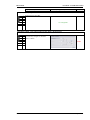
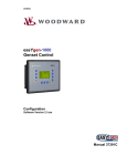
Screw Kit Installation
In order to enhance the protection of the front to IP 65, it is possible to fasten the unit with a screw kit instead of
the clamp fastener hardware.
Proceed as follows to install the unit using the screw kit:
1.
Cut out the panel and drill the holes according to the dimensions in Figure 2-3.
2.
Insert the unit into the panel cutout. Verify that the unit fits correctly in the cutout. If the panel cutout is
not big enough, enlarge it accordingly.
3.
Insert the screws and tighten to 0.6 Nm (5.3 pound inches) of torque. Tighten the screws with a crosswise pattern to ensure even pressure distribution.
NOTE
If the thickness of the panel sheet exceeds 2.5 mm, be sure to use screws with a length of the panel
sheet thickness + 4 mm.
Figure 2-3: Plastic housing - drill plan
© Woodward
Page 17/275
Manual 37527
LS-5 Series - Circuit Breaker Control
Sheet Metal Housing
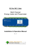
Dimensions
Figure 2-4: Sheet metal housing LS-511 – dimensions
Installation
The unit is to be mounted to the switch cabinet back using four screws with a maximum diameter of 6 mm. Drill
the holes according to the dimensions in Figure 2-5 (dimensions shown in mm).
Figure 2-5: Sheet metal housing - drill plan
Page 18/275
© Woodward
Manual 37527
LS-5 Series - Circuit Breaker Control
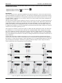
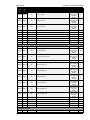
Wiring Diagrams
≡≡≡≡≡≡≡≡≡≡≡≡≡≡≡≡≡≡≡≡≡≡≡≡≡
Figure 2-6: LS-5 Series – wiring diagram
© Woodward
Page 19/275
Manual 37527
LS-5 Series - Circuit Breaker Control
Connections
≡≡≡≡≡≡≡≡≡≡≡≡≡≡≡≡≡≡≡≡≡≡≡≡≡
WARNING
All technical data and ratings indicated in this chapter are not definite! Only the values indicated in
Chapter 7: Technical Data on page 187 are valid!
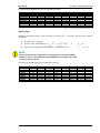
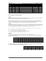
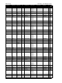
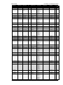
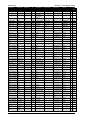
The following chart may be used to convert square millimeters [mm²] to AWG and vice versa:
AWG
30
28
26
24
22
mm²
0.05
0.08
0.14
0.25
0.34
AWG
21
20
18
17
16
mm²
0.38
0.5
0.75
1.0
1.5
AWG
14
12
10
8
6
mm²
2.5
4
6
10
16
AWG
4
2
1
1/0
2/0
mm²
25
35
50
55
70
AWG
3/0
4/0
300MCM
350MCM
500MCM
mm²
95
120
150
185
240
AWG
600MCM
750MCM
1000MCM
mm²
300
400
500
Table 2-2: Conversion chart - wire size
Page 20/275
© Woodward
Manual 37527
LS-5 Series - Circuit Breaker Control
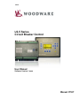
Power Supply
≡≡≡≡≡≡≡≡≡≡≡≡≡≡≡≡≡≡≡≡≡≡≡≡≡
WARNING – Protective Earth / Function Earth
Protective Earth (PE) / Function Earth must be connected to the unit to avoid the risk of electric shock.
The conductor providing the connection must have a wire larger than or equal to 2.5 mm² (14 AWG).
The connection must be performed properly.
• LS-52x: This function earth connection will be made using the screw-plug-terminal 55.
• LS-51x: The function earth terminal 55 is not connected on the LS-51x with sheet metal housing. The
protective earth connection at the sheet metal housing must be used instead (refer to Figure 2-5 on
page 18).
Figure 2-7: Power supply
Figure
A
B
C
Terminal
55
53
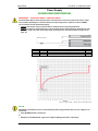
54
Description
Function earth (LS-52x models only)
12/24Vdc (8 to 40.0 Vdc)
0 Vdc
Amax
2.5 mm²
2.5 mm²
2.5 mm²
Table 2-3: Power supply - terminal assignment
Figure 2-8: Power supply - crank waveform at maximum load
NOTE
Woodward recommends to use one of the following slow-acting protective devices in the supply line to
terminal 53:
• Fuse NEOZED D01 6A or equivalent
or
• Miniature Circuit Breaker 6A / Type C (for example: ABB type: S271C6 or equivalent)
© Woodward
Page 21/275
Manual 37527
LS-5 Series - Circuit Breaker Control
Voltage Measuring
≡≡≡≡≡≡≡≡≡≡≡≡≡≡≡≡≡≡≡≡≡≡≡≡≡
NOTE
DO NOT use both sets of voltage measuring inputs. The control unit will not measure voltage correctly
if the 120 V and 480 V inputs are utilized simultaneously.
NOTE
Woodward recommends protecting the voltage measuring inputs with slow-acting fuses rated for 2 to
6 A.
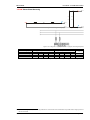
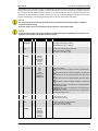
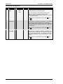
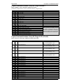
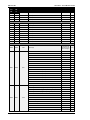
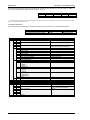
Voltage Measuring: System A
Figure 2-9: Voltage measuring – system A
Figure
A
B
C
D
E
F
G
H
Terminal
14
15
16
17
18
19
20
21
Description
System A Voltage L1
System A Voltage L2
System A Voltage L3
System A Voltage N
120 Vac
480 Vac
120 Vac
480 Vac
120 Vac
480 Vac
120 Vac
480 Vac
Amax
2.5 mm²
2.5 mm²
2.5 mm²
2.5 mm²
2.5 mm²
2.5 mm²
2.5 mm²
2.5 mm²
Table 2-4: Voltage measuring - terminal assignment – system A voltage
NOTE
If parameter 1800 ("SyA. PT sec. rated voltage", refer to Chapter 3: Configuration is configured with a
value between 50 and 130 V, the 120 V input terminals must be used for proper measurement.
If parameter 1800 ("SyA. PT sec. rated voltage", refer to Chapter 3: Configuration is configured with a
value between 131 and 480 V, the 480 V input terminals must be used for proper measurement.
Page 22/275
© Woodward
Manual 37527
LS-5 Series - Circuit Breaker Control
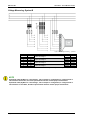
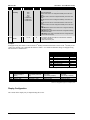
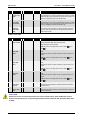
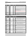
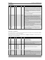
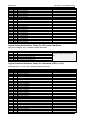
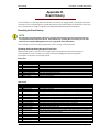
Voltage Measuring: System A, Parameter Setting '3Ph 4W' (3-phase, 4-wire)
A
L1
A
A1
A2
A2
A5
A6
N
C2
C6
C1
B1
B5
B2
C2
B
C
A
B1
C1
L2
B
C
N
L3
L3
A6
N
C2
C
A2
N
C2
B6
B5
C5
A1
C5
C1
C6
L1
A
C6
A2
L2
N
L1
A5
N B6
C5
B2
A1
L1
A1
B2
B1
A5
C1
B
L2
N
A6
C
B
B6
B5
B2
B1
L2
L3
L3
N
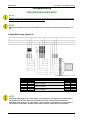
Figure 2-10: Voltage measuring – system A windings, 3Ph 4W
Figure 2-11: Voltage measuring – system A measuring inputs, 3Ph 4W
3Ph 4W
Rated voltage (range)
Measuring range (max.)
Figure
Terminal
Phase
Wiring terminals
[1] 120 V (50 to 130 Veff.)
[5] 480 V (131 to 480 Veff.)
[1] 0 to 150 Vac
[5] 0 to 600 Vac
A
C
E
G
B
D
F
H
14
16
18
20
15
17
19
21
L1
L2
L3
N
L1
L2
L3
N
Note
1
Table 2-5: Voltage measuring - terminal assignment – system A, 3Ph 4W
1
For different voltage systems, different wiring terminals have to be used. Incorrect measurements are possible if both voltage systems use
the same N terminal.
© Woodward
Page 23/275
Manual 37527
LS-5 Series - Circuit Breaker Control
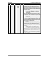
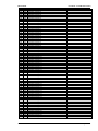
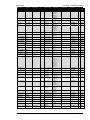
Voltage Measuring: System A, Parameter Setting '3Ph 3W' (3-phase, 3-wire)
A
L1
L1
A
C6
A1
C5
C2
A2
A1
C1
A2
C2
A5
C1
C
B
B2
B1
L2
L3
C
A6
B
B6
B5
B2
B1
L2
L3
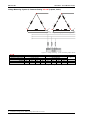
Figure 2-12: Voltage measuring – system A windings, 3Ph 3W
Figure 2-13: Voltage measuring – system A measuring inputs, 3Ph 3W
3Ph 3W
Rated voltage (range)
Measuring range (max.)
Figure
Terminal
Phase
Wiring terminals
[1] 120 V (50 to 130 Veff.)
[5] 480 V (131 to 480 Veff.)
[1] 0 to 150 Vac
[5] 0 to 600 Vac
A
C
E
G
B
D
F
H
14
16
18
20
15
17
19
21
L1
L2
L3
--L1
L2
L3
---
Note
2
Table 2-6: Voltage measuring - terminal assignment – system A, 3Ph 3W
2
For different voltage systems, different wiring terminals have to be used.
Page 24/275
© Woodward
Manual 37527
LS-5 Series - Circuit Breaker Control
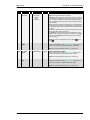
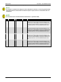
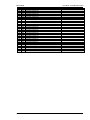
Voltage Measuring: System A, Parameter Setting '1Ph 3W' (1-phase, 3-wire)
A
B5
B1
C2
B6
A1
A5
A2
A6
C6
B2
C1
L1
B6
N
C5
B5
B2
B1
C2
A
C
A1
A2
N
A5
A6
C1
L3
N
C6
C
C5
L3
N
L1
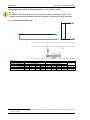
Figure 2-14: Voltage measuring – system A windings, 1Ph 3W
Figure 2-15: Voltage measuring – system A measuring inputs, 1Ph 3W
1Ph 3W
Rated voltage (range)
Measuring range (max.)
Figure
Terminal
Phase
Wiring terminals
[1] 120 V (50 to 130 Veff.)
[5] 480 V (131 to 480 Veff.)
[1] 0 to 150 Vac
[5] 0 to 600 Vac
A
C
E
G
B
D
F
H
14
16
18
20
15
17
19
21
L1
N
L3
N
L1
N
L3
N
Note
3
Table 2-7: Voltage measuring - terminal assignment – system A, 1Ph 3W
3
For different voltage systems, different wiring terminals have to be used. Incorrect measurements are possible if both voltage systems use
the same N terminal.
© Woodward
Page 25/275
Manual 37527
LS-5 Series - Circuit Breaker Control
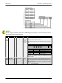
Voltage Measuring: System A, Parameter Setting '1Ph 2W' (1-phase, 2-wire)
NOTE
The 1-phase, 2-wire measurement may be performed phase-neutral or phase-phase. Please note to
configure and wire the LS-5 consistently. Refer to the Chapter 3: Configuration for more information.
'1Ph 2W' Phase-Neutral Measuring
A
A
N
A1
A2
A5
A6
A1
B5
A2
B6
L1
N
L1
N
N
Figure 2-16: Voltage measuring – system A windings, 1Ph 2W (phase-neutral)
Figure 2-17: Voltage measuring – system A measuring inputs, 1Ph 2W (phase-neutral)
1Ph 2W
Rated voltage (range)
Measuring range (max.)
Figure
Terminal
Phase
Wiring terminals
[1] 120 V (50 to 130 Veff.)
[5] 480 V (131 to 480 Veff.)
[1] 0 to 150 Vac
[5] 0 to 600 Vac
A
C
E
G
B
D
F
H
14
16
18
20
15
17
19
21
L1
N
N
N
L1
N
N
N
Note
4
Table 2-8: Voltage measuring - terminal assignment – system A, 1Ph 2W (phase-neutral)
4
For different voltage systems, different wiring terminals have to be used. Incorrect measurements are possible if both voltage systems use
the same N terminal.
Page 26/275
© Woodward
Manual 37527
LS-5 Series - Circuit Breaker Control
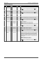
'1Ph 2W' Phase-Phase Measuring
A
A
B
A1
A2
A5
A6
A1
B5
A2
B6
L1
L2
L1
B
L2
Figure 2-18: Voltage measuring – system A windings, 1Ph 2W (phase-phase)
Figure 2-19: Voltage measuring – system A measuring inputs, 1Ph 2W (phase-phase)
1Ph 2W
Rated voltage (range)
Measuring range (max.)
Figure
Terminal
Phase
Wiring terminals
[1] 120 V (50 to 130 Veff.)
[5] 480 V (131 to 480 Veff.)
[1] 0 to 150 Vac
[5] 0 to 600 Vac
A
C
E
G
B
D
F
H
14
16
18
20
15
17
19
21
L1
L2
----L1
L2
-----
Note
5
Table 2-9: Voltage measuring - terminal assignment – system A, 1Ph 2W (phase-phase)
5
For different voltage systems, different wiring terminals have to be used. Incorrect measurements are possible if both voltage systems use
the same N terminal.
© Woodward
Page 27/275
Manual 37527
LS-5 Series - Circuit Breaker Control
Voltage Measuring: System B
Figure 2-20: Voltage measuring – system B
Figure
A
B
C
D
E
F
G
H
Terminal
22
23
24
25
26
27
28
29
Description
System B Voltage L1
System B Voltage L2
System B Voltage L3
System B Voltage N
120 Vac
480 Vac
120 Vac
480 Vac
120 Vac
480 Vac
120 Vac
480 Vac
Amax
2.5 mm²
2.5 mm²
2.5 mm²
2.5 mm²
2.5 mm²
2.5 mm²
2.5 mm²
2.5 mm²
Table 2-10: Voltage measuring - terminal assignment – system B voltage
NOTE
If parameter 1803 ("SyB PT sec. rated voltage", refer to Chapter 3: Configuration) is configured with a
value between 50 and 130 V, the 120 V input terminals must be used for proper measurement.
If parameter 1803 ("SyB PT sec. rated voltage", refer to Chapter 3: Configuration) is configured with a
value between 131 and 480 V, the 480 V input terminals must be used for proper measurement.
Page 28/275
© Woodward
Manual 37527
LS-5 Series - Circuit Breaker Control
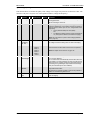
Voltage Measuring: System B, Parameter Setting '3Ph 4W' (3-phase, 4-wire)
A
L1
A
A1
A2
A2
A5
A6
N
C2
C6
B1
B5
B2
C2
B
C
A
B1
C1
L2
B
C
N
L3
L3
A2
A6
N
C2
C
A2
N
C2
B6
B5
C5
A1
C5
C1
C6
L1
A
C6
A5
L2
N
L1
A1
N B6
C5
B2
C1
L1
A1
B2
B1
A5
C1
B
L2
N
A6
C
B
B6
B5
B2
B1
L2
L3
L3
N
Figure 2-21: Voltage measuring – system B PT windings, 3Ph 4W
Figure 2-22: Voltage measuring – system B measuring inputs, 3Ph 4W
3Ph 4W
Rated voltage (range)
Measuring range (max.)
Figure
Terminal
Phase
Wiring terminals
[1] 120 V (50 to 130 Veff.)
[5] 480 V (131 to 480 Veff.)
[1] 0 to 150 Vac
[5] 0 to 600 Vac
A
C
E
G
B
D
F
H
22
24
26
28
23
25
27
29
L1
L2
L3
N
L1
L2
L3
N
Note
6
Table 2-11: Voltage measuring - terminal assignment – system B, 3Ph 4W
6
For different voltage systems, different wiring terminals have to be used. Incorrect measurements are possible if both voltage systems use
the same N terminal.
© Woodward
Page 29/275
Manual 37527
LS-5 Series - Circuit Breaker Control
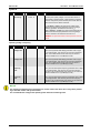
Voltage Measuring: System B, Parameter Setting '3Ph 3W' (3-phase, 3-wire)
A
L1
L1
A
C6
A1
C5
C2
A2
A1
C1
A2
C2
A5
C1
C
B
B2
B1
L2
L3
C
A6
B
B6
B5
B2
B1
L2
L3
Figure 2-23: Voltage measuring – system B PT windings, 3Ph 3W
Figure 2-24: Voltage measuring – system B measuring inputs, 3Ph 3W
3Ph 3W
Rated voltage (range)
Measuring range (max.)
Figure
Terminal
Phase
Wiring terminals
[1] 120 V (50 to 130 Veff.)
[5] 480 V (131 to 480 Veff.)
[1] 0 to 150 Vac
[5] 0 to 600 Vac
A
C
E
G
B
D
F
H
22
24
26
28
23
25
27
29
L1
L2
L3
--L1
L2
L3
---
Note
7
Table 2-12: Voltage measuring - terminal assignment – system B, 3Ph 3W
7
For different voltage systems, different wiring terminals have to be used.
Page 30/275
© Woodward
Manual 37527
LS-5 Series - Circuit Breaker Control
Voltage Measuring: System B, Parameter Setting '1Ph 3W' (1-phase, 3-wire)
A
B5
B1
C2
B6
A1
A5
A2
A6
C6
B2
C1
L1
B6
N
C5
B5
B2
B1
C2
A
C
A1
A2
N
A5
A6
C1
L3
N
C6
C
C5
L3
N
L1
Figure 2-25: Voltage measuring – system B PT windings, 1Ph 3W
Figure 2-26: Voltage measuring - mains system B measuring inputs, 1Ph 3W
1Ph 3W
Rated voltage (range)
Measuring range (max.)
Figure
Terminal
Phase
Wiring terminals
[1] 120 V (50 to 130 Veff.)
[5] 480 V (131 to 480 Veff.)
[1] 0 to 150 Vac
[5] 0 to 600 Vac
A
C
E
G
B
D
F
H
22
24
26
28
23
25
27
29
L1
N
L3
N
L1
N
L3
N
Note
8
Table 2-13: Voltage measuring - terminal assignment – system B, 1Ph 3W
8
For different voltage systems, different wiring terminals have to be used. Incorrect measurements are possible if both voltage systems use
the same N terminal.
© Woodward
Page 31/275
Manual 37527
LS-5 Series - Circuit Breaker Control
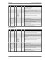
Voltage Measuring: System B, Parameter Setting '1Ph 2W' (1-phase, 2-wire)
NOTE
The 1-phase, 2-wire measurement may be performed phase-neutral or phase-phase. Please note to
configure and wire the LS-5 consistently. Refer to the Chapter 3: Configuration for more information.
'1Ph 2W' Phase-Neutral Measuring
A
A
N
A1
A2
A5
A6
A1
B5
A2
B6
L1
N
L1
N
N
Figure 2-27: Voltage measuring – system B PT windings, 1Ph 2W (phase-neutral)
Figure 2-28: Voltage measuring – system B measuring inputs, 1Ph 2W (phase-neutral)
1Ph 2W
Rated voltage (range)
Measuring range (max.)
Figure
Terminal
Phase
Wiring terminals
[1] 120 V (50 to 130 Veff.)
[5] 480 V (131 to 480 Veff.)
[1] 0 to 150 Vac
[5] 0 to 600 Vac
A
C
E
G
B
D
F
H
22
24
26
28
23
25
27
29
L1
N
N
N
L1
N
N
N
Note
9
Table 2-14: Voltage measuring - terminal assignment – system B, 1Ph 2W (phase-neutral)
9
For different voltage systems, different wiring terminals have to be used. Incorrect measurements are possible if both voltage systems use
the same N terminal.
Page 32/275
© Woodward
Manual 37527
LS-5 Series - Circuit Breaker Control
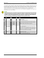
'1Ph 2W' Phase-Phase Measuring
A
A
B
A1
A2
A5
A6
A1
B5
A2
B6
L1
L2
L1
B
L2
Figure 2-29: Voltage measuring – system B PT windings, 1Ph 2W (phase-phase)
Figure 2-30: Voltage measuring – system B measuring inputs, 1Ph 2W (phase-phase)
1Ph 2W
Rated voltage (range)
Measuring range (max.)
Figure
Terminal
Phase
Wiring terminals
[1] 120 V (50 to 130 Veff.)
[5] 480 V (131 to 480 Veff.)
[1] 0 to 150 Vac
[5] 0 to 600 Vac
A
C
E
G
B
D
F
H
22
24
26
28
23
25
27
29
L1
L2
----L1
L2
-----
Note
10
Table 2-15: Voltage measuring - terminal assignment – system B, 1Ph 2W (phase-phase)
10 For different voltage systems, different wiring terminals have to be used. Incorrect measurements are possible if both voltage systems use
the same N terminal.
© Woodward
Page 33/275
Manual 37527
LS-5 Series - Circuit Breaker Control
Current Measuring
≡≡≡≡≡≡≡≡≡≡≡≡≡≡≡≡≡≡≡≡≡≡≡≡≡
CAUTION
Before disconnecting the device, ensure that the current transformers/CT are short-circuited.
System A Current
NOTE
Generally, one line of the current transformers secondary is to be grounded close to the CT.
Figure 2-31: Current measuring – System A
Figure
A
B
C
D
E
F
Terminal
7
4
6
4
5
4
Description
System A Current L3
System A Current L3 (GND)
System A Current L2
System A Current L2 (GND)
System A Current L1
System A Current L1 (GND)
Amax
2.5 mm²
2.5 mm²
2.5 mm²
2.5 mm²
2.5 mm²
2.5 mm²
Table 2-16: Current measuring - terminal assignment – system A current
Page 34/275
© Woodward
Manual 37527
LS-5 Series - Circuit Breaker Control
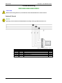
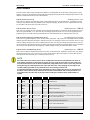
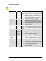
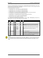
Current Measuring: System A, Parameter Setting 'L1 L2 L3'
Figure 2-32: Current measuring – system A, L1 L2 L3
L1 L2 L3
Terminal
Phase
4
s1 (k) L1
5
s2 (l) L1
Wiring terminals
4
6
s1 (k) L2
s2 (l) L2
4
s1 (k) L3
7
s2 (l) L3
Notes
Table 2-17: Current measuring - terminal assignment – system A, L1 L2 L3
Current Measuring: System A, Parameter Setting 'Phase L1', 'Phase L2' & 'Phase L3'
Phase L1
Phase L2
Phase L3
Figure 2-33: Current measuring – system A, phase Lx
Phase L1
Wiring terminals
Notes
Terminal
Phase
4
s1 (k) L1
5
s2 (l) L1
4
---
6
---
4
---
7
---
Terminal
Phase
4
---
5
---
4
s1 (k) L2
6
s2 (l) L2
4
---
7
---
Terminal
Phase
Phase L1 and L3
Terminal
Phase
4
---
5
---
4
---
6
---
4
s1 (k) L3
7
s2 (l) L3
4
s1 (k) L1
5
s2 (l) L1
4
---
6
---
4
s1 (k) L3
7
s2 (l) L3
Phase L2
Phase L3
11
Table 2-18: Current measuring - terminal assignment – system A, phase Lx
11 This is valid if the generator voltage measurement is configured to 1Ph 3W (refer to
Voltage Measuring: System A, Parameter Setting '1Ph 3W' (1-phase, 3-wire) on page 20).
© Woodward
Page 35/275
Manual 37527
LS-5 Series - Circuit Breaker Control
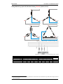
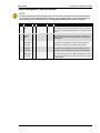
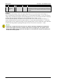
Power Measuring
≡≡≡≡≡≡≡≡≡≡≡≡≡≡≡≡≡≡≡≡≡≡≡≡≡
If the unit's current transformers are wired according to the diagram shown, the following values are displayed.
Parameter
Positive real power
Inductive (cos φ)
Description
Power flow from System B
to System A
Inductive power flow from
System B to System A
Sign displayed
+ Positive
+ Positive
Figure 2-34: Power measuring - direction of power
Figure
A
B
Terminal
5
4
Description
System A Current L1
System A Current GND
Amax
2.5 mm²
2.5 mm²
Table 2-19: Power measuring - terminal assignment
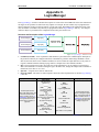
Power Factor Definition
≡≡≡≡≡≡≡≡≡≡≡≡≡≡≡≡≡≡≡≡≡≡≡≡≡
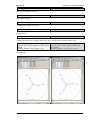
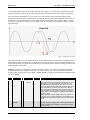
The phasor diagram is used from the System B view. Power factor is defined as follows.
Power Factor is defined as a ratio of the real power to apparent power. In a purely resistive circuit, the voltage
and current waveforms are instep resulting in a ratio or power factor of 1.00 (often referred to as unity). In an inductive circuit the current lags behind the voltage waveform resulting in usable power (real power) and unusable
power (reactive power). This results in a positive ratio or lagging power factor (i.e. 0.85lagging). In a capacitive
circuit the current waveform leads the voltage waveform resulting in usable power (real power) and unusable
power (reactive power). This results in a negative ratio or a leading power factor (i.e. 0.85leading).
Inductive: Electrical load whose current waveform
lags the voltage waveform thus having a lagging power factor. Some inductive loads such as electric motors
have a large startup current requirement resulting in
lagging power factors.
Capacitive: Electrical load whose current waveform
leads the voltage waveform thus having a leading
power factor. Some capacitive loads such as capacitor
banks or buried cable result in leading power factors.
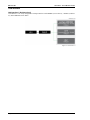
Different power factor displays at the unit:
i0.91 (inductive)
Page 36/275
c0.93 (capacitive)
© Woodward
Manual 37527
lg.91 (lagging)
LS-5 Series - Circuit Breaker Control
ld.93 (leading)
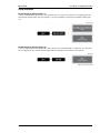
Reactive power display at the unit:
70 kvar (positive)
-60 kvar (negative)
Output at the interface:
+ (positive)
- (negative)
In relation to the voltage, the current is
lagging
leading
The generator is
over excited
under excited
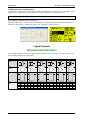
Control: If the control unit is equipped with a power factor controller while in parallel with the utility:
A voltage lower "-" signal is output as long as the
measured value is "more inductive" than the reference
setpoint
Example: measured = i0.91; setpoint = i0.95
A voltage raise "+" signal is output as long as the
measured value is "more capacitive" than the reference setpoint
Example: measured = c0.91; setpoint = c0.95
Phasor diagram:
inductive
© Woodward
capacitive
Page 37/275
Manual 37527
LS-5 Series - Circuit Breaker Control
Discrete Inputs
≡≡≡≡≡≡≡≡≡≡≡≡≡≡≡≡≡≡≡≡≡≡≡≡≡
Discrete Inputs: Signal Polarity
The discrete inputs are electrically isolated which permits the polarity of the connections to be either positive or
negative.
NOTE
All discrete inputs must use the same polarity, either positive or negative signals, due to the common
ground.
Discrete Inputs: Positive Polarity Signal
Figure 2-35: Discrete inputs - alarm/control input - positive signal
Discrete Inputs: Negative Polarity Signal
Figure 2-36: Discrete inputs - alarm/control input - negative signal
Terminal
Com.
Term.
A
43
GND
common
ground
B
44
Description
Discrete input [DI 01]
Amax
Lock monitoring *1
2.5 mm²
*1
45
Discrete input [DI 02]
Remote acknowledge
46
Discrete input [DI 03]
Enable decoupling *1
2.5 mm²
2.5 mm²
47
Discrete input [DI 04]
2.5 mm²
48
Discrete input [DI 05]
49
Discrete input [DI 06]
50
Discrete input [DI 07]
Immediate open CB A *1
Reply: Isolation switch is
open *1
Open CB A
(with unloading) *1
Enable to close CB A *1
51
Discrete input [DI 08]
Reply: CB A is open
2.5 mm²
2.5 mm²
2.5 mm²
2.5 mm²
Table 2-20: Discrete input - terminal assignment
*1 = default value / configurable via LogicsManager
Page 38/275
© Woodward
Manual 37527
LS-5 Series - Circuit Breaker Control
Discrete Inputs: Operation Logic
Discrete inputs may be configured to normally open (N.O.) or normally closed (N.C.) states. In the state N.O., no
potential is present during normal operation; if an alarm is issued or control operation is performed, the input is
energized. In the state N.C., a potential is continuously present during normal operation; if an alarm is issued or
control operation is performed, the input is de-energized.
The N.O. or N.C. contacts may be connected to the signal terminal as well as to the ground terminal of the discrete input. See previous chapter Discrete Inputs: Signal on page 38 for details.
Figure 2-37: Discrete inputs - alarm/control inputs - operation logic
© Woodward
Page 39/275
Manual 37527
LS-5 Series - Circuit Breaker Control
Relay Outputs
(LogicsManager)
≡≡≡≡≡≡≡≡≡≡≡≡≡≡≡≡≡≡≡≡≡≡≡≡≡
Figure 2-38: Relay outputs
Terminal
Description
A
C
Form A, N.O. make contact
30
31
Relay output [R 01]
Fixed to
“Ready for operation”
32
33
Relay output [R 02]
Preconfigured to “Horn”
34
35
Relay output [R 03]
36
37
Relay output [R 04]
Terminal
Amax
Preconfigured to
“System B not OK”
Preconfigured to
“System A not OK”
N.O.
2.5 mm²
SW
2.5 mm²
SW
2.5 mm²
SW
2.5 mm²
Description
Amax
A
B
C
Form C, N.O. make contact, N.C.
38
39
40
Relay output [R 05]
Terminal
Description
A
Form A, N.O. make contact
C
Type
Type
Fixed to
“Open CB A”
SW
2.5 mm²
Amax
Type
Fixed to “Close CB A”
in [CB A: Two relay]
mode
41
42
Relay output [R 06]
otherwise
N.O.
2.5 mm²
Preconfigured to
“All alarm classes”
LogicsManager.using the function LogicsManager it is possible to freely program the relays
SW
N.O.
All application modes
Switchable via software
Normally open (make) contact
Table 2-21: Relay outputs - terminal assignment
Page 40/275
© Woodward
Manual 37527
LS-5 Series - Circuit Breaker Control
CAUTION
The discrete output "Ready for operation OFF" must be integrated into the alarm chain to make sure
that if this relay falls off and an appropriate action can be taken.
NOTE
Refer to Appendix A: Connecting 24 V Relays on page 192 for interference suppressing circuits when
connecting 24 V relays.
© Woodward
Page 41/275
Manual 37527
LS-5 Series - Circuit Breaker Control
Interfaces
≡≡≡≡≡≡≡≡≡≡≡≡≡≡≡≡≡≡≡≡≡≡≡≡≡
RS-485 Serial Interface
Terminal
58
59
Description
RS-485-B (TxD-)
RS-485-A (TxD+)
Amax
2.5 mm²
2.5 mm²
Table 2-22: RS-485 interface - pin assignment
RS-485 Half-Duplex
Figure 2-39: RS-485 - connection for half-duplex operation
Service Port (RS-232)
The optional Woodward Direct Configuration Cable (DPC) must be connected to the Service Port. The DPC
adapter has a single RS-232 interface which is used for the configuration setup of the LS-5 Series. (refer to “DPC
- Direct Configuration Cable” on page 46)
Figure 2-40: RS-232 interface - overview
Terminal
1
2
3
4
5
6
7
8
9
Description
not connected
RxD (receive data)
TxD (transmit data)
not connected
GND (system ground)
not connected
RTS (request to send)
CTS (clear to send)
not connected
Amax
N/A
N/A
N/A
N/A
N/A
N/A
N/A
N/A
N/A
Table 2-23: RS-232 interface (DPC) - pin assignment
Page 42/275
© Woodward
Manual 37527
LS-5 Series - Circuit Breaker Control
CAN Bus Interface
Terminal
56
57
Description
CAN-L
CAN-H
Amax
2.5 mm²
2.5 mm²
Table 2-24: CAN bus - pin assignment
© Woodward
Page 43/275
Manual 37527
LS-5 Series - Circuit Breaker Control
CAN Bus Topology
NOTE
Please note that the CAN bus must be terminated with a resistor, which corresponds to the impedance
of the cable (e.g. 120 Ohms, 1/4 W) at both ends. The termination resistor is connected between CAN-H
and CAN-L.
Figure 2-41: Interfaces - CAN bus - termination
Troubleshooting Possible CAN Bus Problems
If data is not transmitting on the CAN bus, check the following for common CAN bus communication problems:
• A T-structure bus is utilized
• CAN-L and CAN-H are interchanged
• Not all devices on the bus are using identical Baud rates
• Terminating resistor(s) missing
• The configured baud rate is too high for bus length
• The CAN bus cable is routed in close proximity with power cables
Woodward recommends the use of shielded, twisted-pair cables for the CAN bus (i.e.: Lappkabel Unitronic
LIYCY (TP) 2×2×0.25, UNITRONIC-Bus LD 2×2×0.22).
Maximum CAN Bus Length
The maximum length of the communication bus wiring is dependent on the configured Baud rate. Refer to Table
2-25 for the maximum bus length (Source: CANopen; Holger Zeltwanger (Hrsg.); 2001 VDE VERLAG GMBH,
Berlin und Offenbach; ISBN 3-8007-2448-0).
Baud rate
1000 kbit/s
800 kbit/s
500 kbit/s
250 kbit/s
125 kbit/s
50 kbit/s
20 kbit/s
Max. length
25 m
50 m
100 m
250 m
500 m
1000 m
2500 m
Table 2-25: Maximum CAN bus length
The maximum specified length for the communication bus wiring might not be achieved if poor quality wire is
utilized, there is high contact resistance, or other conditions exist. Reducing the baud rate may overcome these issues.
Page 44/275
© Woodward
Manual 37527
LS-5 Series - Circuit Breaker Control
NOTE
When you are using 20 kbit/s or 50 kbit/s together with Toolkit, we recommend to set Parameter 9921
“Transfer rate fast message” to 0,30 s.
Bus Shielding
The table below gives a detailed overview how the different interfaces needs to be shielded.
Device
LS-5 Series
Interface
CAN bus
Shielding
External RC element
Table 2-26: Bus shielding
Figure 2-42: Interfaces – shielding (external RC element)
© Woodward
Page 45/275
Manual 37527
LS-5 Series - Circuit Breaker Control
DPC - Direct Configuration Cable
The LS-5 provides a Service Port for connecting a computer via the DPC (direct configuration cable). The configuration interface is the RJ45 socket on the side of the LS-5 housing.
NOTE
The connection cable delivered with the DPC must be used between DPC and LS-5 to ensure proper
functionality of the LS-5. An extension or utilization of different cable types for the connection between
LS-5 and DPC may result a malfunction of the LS-5. This may possibly result in damage to components
of the system. If an extension of the data connection line is required, only the serial cable (RS-232) between DPC and laptop/PC may be extended. It is recommended to use an industry standard cable for
this.
NOTE
For a continuous operation with the direct configuration cable DPC (e.g. remote control of the LS-5), it
is required to use at least revision F (P/N 5417-557 Rev. F) of the DPC. When using a DPC of an earlier
revision, problems may occur in continuous operation. It is recommended to use an industry standard
serial (RS-232) cable to connect the DPC with the laptop/PC for continuous operation. The shield connector (6.3mm tab connector) at the DPC of revision F (P/N 5417-557 Rev. F) and above must be connected to ground.
Page 46/275
© Woodward
Manual 37527
LS-5 Series - Circuit Breaker Control
Chapter 3.
Configuration
Configuration Via Front Panel
≡≡≡≡≡≡≡≡≡≡≡≡≡≡≡≡≡≡≡≡≡≡≡≡≡
Operation of the unit via the front panel is explained in “Chapter 4: Operation”. This chapter will familiarize you
with the unit, the meanings/functions of the buttons, and the display.
© Woodward
Page 47/275
Manual 37527
LS-5 Series - Circuit Breaker Control
Configuration Via PC
≡≡≡≡≡≡≡≡≡≡≡≡≡≡≡≡≡≡≡≡≡≡≡≡≡
Install ToolKit Configuration and Visualization Software
NOTE
Woodward’s ToolKit software is required to configure the unit via PC.
ToolKit Version 3.5.3 or higher
Install ToolKit Software
1.
2.
3.
Please insert the enclosed Product CD in the CD-ROM drive of your computer
The CD is going to start automatically (autostart function needs to be activated)
Please go to the section “Software” and follow the instructions described there
Alternatively ToolKit can be downloaded from our Website. Please proceed as follows:
1.
2.
3.
4.
5.
6.
Go to http://www.woodward.com/software
Select ToolKit in the list and click the “Go” button
Click “More Info” to get further information about ToolKit
Choose the preferred software version and click “Download”
Now you need to login with your e-mail address or register first
The download will start immediatly
Minimum system requirements for ToolKit:
•
•
•
•
•
•
•
Microsoft Windows® 7, Vista, XP (32- & 64-bit)
Microsoft .NET Framework Ver. 3.5
600 MHz Pentium® CPU
96 MB of RAM
Minimum 800 by 600 pixel screen with 256 colors
Serial Port
CD-ROM drive
NOTE
Microsoft .NET Framework 3.5 must be installed on your computer to be able to install ToolKit. If not already installed, Microsoft .NET Framework 3.5 will be installed automatically. You must be connected
to the internet for this. Alternatively you can use the .NET Framework 3.5 installer which can be found
on the Product CD.
Page 48/275
© Woodward
Manual 37527
LS-5 Series - Circuit Breaker Control
Install ToolKit Configuration Files
1.
2.
3.
Please insert the enclosed Product CD in the CD-ROM drive of your computer
The CD is going to start automatically (autostart function needs to be activated)
Please go to the section “Configuration Files” and follow the instructions described there
Alternatively ToolKit configuration files can be downloaded from our Website. Please proceed as follows:
1.
2.
3.
4.
Go to http://www.woodward.com/software/configfiles/
Please insert the part number (P/N) and revision of your device into the corresponding fields
Select ToolKit in the application type list
Click “Search”
NOTE
ToolKit is using the following files:
*.WTOOL
1
2
File name composition: [P/N1]* -[Revision]_[Language ID]_[P/N2]* -[Revision]_[# of visualized
gens].WTOOL
Example file name:
8440-1234-NEW_US_5418-1234-NEW.WTOOL
Content of the file:
Display screens and pages for online configuration, which are associated with
the respective *.SID file
*.SID
2
File name composition: [P/N2]* -[Revision].SID
Example file name:
5418-1234-NEW.SID
Content of the file:
All display and configuration parameters available in ToolKit
*.WSET
File name composition: [user defined].WSET
Example file name:
easYgen_settings.WSET
Content of the file:
Default settings of the ToolKit configuration parameters provided by the SID
file or user-defined settings read out of the unit.
1
* P/N1 = Part number of the unit
2
* P/N2 = Part number of the software in the unit
© Woodward
Page 49/275
Manual 37527
LS-5 Series - Circuit Breaker Control
Starting ToolKit Software
1.
2.
Start ToolKit via Windows Start menu -> Programs ->Woodward -> ToolKit 3.x
Please press the button “Open Tool”
3.
Go to the “Application” folder and open then the folder equal to the part number (P/N) of your device
(e.g. 8440-1234). Select the wtool file (e.g. 8440-1234-NEW_US_5418-1234-NEW.wtool) and click
“Open” to start the configuration file
Now the home page of the ToolKit configuration screen appears
4.
Page 50/275
© Woodward
Manual 37527
LS-5 Series - Circuit Breaker Control
Configure ToolKit Software
1.
Start the configuration by using the toolbar. Please go to Tools -> Options
2.
The options window will be displayed
a
b
3.
a. Adjust the default locations of the configuration files
b. The displayed language can be selected here
The changes become effective after clicking “OK”
NOTE
Please use the ToolKit online help for further information.
© Woodward
Page 51/275
Manual 37527
LS-5 Series - Circuit Breaker Control
Connect ToolKit and the LS-5 Unit
For configuration of the unit via ToolKit please proceed as follows:
1.
2.
3.
4.
5.
6.
Connect the null modem communications cable between your laptop/PC and the DPC cable. Plug the
null modem cable into the RS-232 serial port of the DPC cable and the other side to a serial COM port
of the laptop/PC. If the laptop/PC does not have a serial port to connect the null modem cable to, use a
USB to serial adapter. Now connect the DPC cable to the LS-5.
Open ToolKit via Windows Start menu -> Programs -> Woodward -> ToolKit 3.x
From the main ToolKit window, click File then select “Open Tool”..., or click the Open Tool icon
on the tool bar.
Locate and select the desired tool file (*.WTOOL) in the ToolKit data file directory and click Open.
From the main ToolKit window, click Device then click “Connect”, or select the Connect icon
on
the toolbar.
The connect dialog window will open if the option is enabled.
a
b
7.
8.
a. Select the COM port that is connected to the communication cable.
b. Click the “Connect” button.
The identifier of the device that ToolKit is connected to, will display in the status bar.
If the Communications window opens, select “ToolConfigurator” under Tool Device and close the
Communications window.
9. If the device is security enabled, the Login dialog will appear.
10. Now you are able to edit the LS-5 parameters in the main window. Any changes made are written to the
control memory automatically.
Page 52/275
© Woodward
Manual 37527
LS-5 Series - Circuit Breaker Control
SID Files for Using ToolKit on the CAN Bus With Other CANopen Devices
If a PC with ToolKit is connected to the LS-5 via a CAN bus with other external CANopen devices (like a Phoenix Contact I/O expansion board, for example), it may happen that ToolKit cannot establish a connection with the
LS-5 because it looks for a SID file for such an external device, which does not exist.
A special *.sid file can be created in this case. Contact Woodward for support or create a *.sid file with the following content:
<?xml version="1.0" encoding="utf-8"?>
<ServiceInterfaceDefinition xmlns:xsi="http://www.w3.org/2001/XMLSchema-instance" Identifier="[add the
required device application name here]" Specification="EmptyFile">
</ServiceInterfaceDefinition>
The file name must be the same as the Identifier plus the extension *.sid. The file must be stored to the configured SID file directory.
NOTE
Depending on the computer used and the installed operation system, problems with the communication via an infrared connection may occur.
NOTE
If your computer is equipped with a Bluetooth interface please deactivate it temporarily in the Windows
system control menu in the case that ToolKit is freezing building up a connection.
NOTE
It is also possible to connect to the unit via CAN bus. If a suitable CAN adapter is used, this may be selected in the Connect window. We recommend to use the IXXAT USB-to-CAN converter using the VCI
V3 driver.
Be sure to configure the correct baud rate and timeout in the Properties dialog of the Connect window.
The Password for CAN Interface 1 (parameter 10402 on page 59) must be entered before being able to
edit the parameters.
© Woodward
Page 53/275
Manual 37527
LS-5 Series - Circuit Breaker Control
View LS-5 Data with ToolKit
The following figure shows an example visualization screen of ToolKit:
Figure 3-1: ToolKit - visualization screen
Navigation through the various visualization and configuration screens is performed by clicking on
the
and
icons, by selecting a navigation button (e.g.
), or by selecting a screen from the drop-down
list to the right of the arrow icons.
It is possible to view a trend chart of up to eight values with the trending tool utility of ToolKit. The following
figure shows a trending screen of the measured battery voltage value:
Figure 3-2: ToolKit - analog value trending screen
Each visualization screen provides for trending of monitored values by right-clicking on a value and selecting the
"Add to trend" function. Trending is initiated by clicking on the Start button. Clicking the Export… button will
save the trend data to a Comma Separated Values (CSV) file for viewing, editing or printing with office software,
like Microsoft Excel, etc. The Properties… button is used to define high and low limits of the scale, sample rate,
displayed time span and color of the graph.
Page 54/275
© Woodward
Manual 37527
LS-5 Series - Circuit Breaker Control
Configure the LS-5 with ToolKit
The following figure shows an example configuration screen of ToolKit:
Figure 3-3: ToolKit - configuration screen
Entering a new value or selecting a value from a defined list will change the value in a field. The new value is
written to the controller memory by changing to a new field or pressing the Enter key.
Navigation through the various configuration and visualization screens is performed by clicking on the
and
icons, by selecting a navigation button (e.g.
), or by selecting a screen from the drop-down list to
the right of the arrow icons.
© Woodward
Page 55/275
Manual 37527
LS-5 Series - Circuit Breaker Control
Parameters
≡≡≡≡≡≡≡≡≡≡≡≡≡≡≡≡≡≡≡≡≡≡≡≡≡
To all parameters are assigned unique “Parameter Identification Numbers (ID)”. The parameter identification
number may be used to reference individual parameters listed in this manual. This parameter identification number is also displayed in the ToolKit configuration screens next to the respective parameter.
Language / Clock Configuration
The following parameters are used to set the unit language, the current date and time, and the daylight saving
time feature.
NOTE
If an Asian language is configured, some parameter screens may be displayed with an empty space at
the bottom of the parameter list, which may be interpreted as an end of the list, although more parameters exist and are displayed when scrolling down.
ID
Parameter
CL
Setting range
Default
Description
1700
Language
0
Deutsch /
English /
Chinese /
Português /
Japanese /
Russky /
Türkçe /
Español /
Français /
Italiano /
Polski /
Englisch
The desired language for the unit display text is configured here.
1710
Hour
0
0 to 23 h
0
The hour of the clock time is set here. Example:
0: 0th hour of the day (midnight).
23: 23rd hour of the day (11 pm).
1709
Minute
0
0 to 59 min
-
The minute of the clock time is set here. Example:
0: 0th minute of the hour.
59: 59th minute of the hour.
1708
Second
0
0 to 59 s
-
The second of the clock time is set here. Example:
0: 0th second of the minute.
59: 59th second of the minute.
1698
Transfer time
to clock
0
Yes / No
No
Yes: Adjusted time will be transfered to the unit.
No: Adjusted time will be not transfered to the unit.
NOTE: This parameter may only be configured using ToolKit.
1711
Day
0
1 to 31
-
The day of the date is set here. Example:
1: 1st day of the month.
31: 31st day of the month.
1712
Month
0
1 to 12
-
The month of the date is set here. Example:
1: 1st month of the year.
12: 12th month of the year.
1713
Year
0
0 to 99
-
The year of the date is set here. Example:
0: Year 2000.
99: Year 2099.
1699
Transfer date
to clock
0
Yes / No
No
Yes: Adjusted date will be transfered to the unit.
No: Adjusted date will be not transfered to the unit.
NOTE: This parameter may only be configured using ToolKit.
Page 56/275
© Woodward
Manual 37527
LS-5 Series - Circuit Breaker Control
The daylight saving time feature enables to automatically adjust the real-time clock to local daylight saving time
(DST) provisions. If daylight saving time is enabled, the real-time clock will automatically be advanced by one
hour when the configured DST begin date and time is reached and falls back again by one hour when the configured DST end date and time is reached. If the unit is used in the southern hemisphere, the DST function will be
inverted automatically, if the DST begin month is later in the year than the DST end month.
NOTE
Do not change the time manually during the hour of the automatic time change if DST is enabled to
avoid a wrong time setting.
Events or alarms, which occur during this hour might have a wrong time stamp.
NOTE
The following parameters will only be displayed, if Daylight saving time (parameter 4591) has been configured to “On” and the enter button has been pressed.
ID
Parameter
CL
Setting range
Default
Description
4591
Daylight
saving time
2
On / Off
Off
4594
DST begin
time
2
0 to 23 h
2
4598
DST begin
weekday
2
Sunday /
Monday /
Tuesday /
Wednesday /
Thursday /
Friday /
Saturday
Sunday
4592
DST begin
nth weekday
2
1st /
2nd /
3rd /
4th /
Last /
LastButOne /
LastButTwo /
LastButThree
Last
4593
DST begin
month
2
1 to 12
3
The month for the DST begin date is configured here. Example:
1: 1st month of the year.
12: 12th month of the year.
4597
DST end
time
2
0 to 23
3
The real-time clock will fall back by one hour when this time is
reached on the DST end date. Example:
0: 0th hour of the day (midnight).
23: 23rd hour of the day (11 pm).
4599
DST end
weekday
2
Sunday /
Monday /
Tuesday /
Wednesday /
Thursday /
Friday /
Saturday
Sunday
© Woodward
Enables the daylight saving time.
On: Daylight saving time is enabled.
Off: Daylight saving time is disabled.
The real-time clock will be advanced by one hour when this time is
reached on the DST begin date. Example:
0: 0th hour of the day (midnight).
23: 23rd hour of the day (11 pm).
The weekday for the DST begin date is configured here.
The order number of the weekday for the DST begin date is configured here. Example:
1st: DST starts on the 1st configured weekday of the DST begin
month.
2nd: DST starts on the 2nd configured weekday of the DST begin
month.
3rd: DST starts on the 3rd configured weekday of the DST begin
month.
4th: DST starts on the 4th configured weekday of the DST begin
month.
Last: DST starts on the last configured weekday of the DST begin
month.
LastButOne: DST starts on the last but one configured weekday
of the DST begin month.
LastButTwo: DST starts on the last but two configured weekday
of the DST begin month.
LastButThree: DST starts on the last but three configured weekday of the DST begin month.
The weekday for the DST end date is configured here.
Page 57/275
Manual 37527
ID
Parameter
LS-5 Series - Circuit Breaker Control
CL
Setting range
Default
4595
DST end nth
weekday
2
1st /
2nd /
3rd /
4th /
Last /
LastButOne /
LastButTwo /
LastButThree
Last
4596
DST end
month
2
1 to 12
10
Description
The order number of the weekday for the DST end date is configured here. Example:
1st: DST ends on the 1st configured weekday of the DST end
month.
2nd: DST ends on the 2nd configured weekday of the DST end
month.
3rd: DST ends on the 3rd configured weekday of the DST end
month.
4th: DST ends on the 4th configured weekday of the DST end
month.
Last: DST ends on the last configured weekday of the DST end
month.
LastButOne: DST ends on the last but one configured weekday
of the DST end month.
LastButTwo: DST ends on the last but two configured weekday
of the DST end month.
LastButThree: DST ends on the last but three configured weekday of the DST end month.
The month for the DST end date is configured here. Example:
1: 1st month of the year.
12: 12th month of the year.
Example:
If daylight saving time starts at 2:00 am on the 2nd Sunday in March and ends at 2:00 am on the 1st Sunday in November, the unit has to be configured like shown in Table 3-1 to enable an automatic change to daylight saving
time and back to standard time.
ID
4591
4594
4598
4592
4593
4597
4599
4595
4596
Parameter
Daylight saving time
DST begin time
DST begin weekday
DST begin nth weekday
DST begin month
DST end time
DST end weekday
DST end sunday
DST end month
Setting
On
2
Sunday
2nd
3
2
Sunday
1st
11
Table 3-1: Daylight saving time - configuration example
Year
2008
2009
2010
USA, Canada
DST Begins 2 a.m.
(Second Sunday in
March)
March 9, 2008
March 8, 2009
March 14, 2010
DST Ends 3 a.m.
(First Sunday in November)
November 2, 2008
November 1, 2009
November 7, 2010
European Union
DST Begins 1 a.m.
UTC=GMT
(Last Sunday in March)
March 30, 2008
March 29, 2009
March 28, 2010
DST Ends 2 a.m.
UTC=GMT
(Last Sunday in October)
October 26, 2008
October 25, 2009
October 31, 2010
Table 3-2: Daylight saving time - examplary dates
Display Configuration
The contrast of the display may be adjusted using this screen.
Page 58/275
© Woodward
Manual 37527
LS-5 Series - Circuit Breaker Control
Enter Password
The LS-5 Series utilizes a password protected multi-level configuration access hierarchy. This permits varying
degrees of access to the parameters being granted by assigning unique passwords to designated personnel. A distinction is made between the access levels as follows:
Code level CL0 (User Level)
Standard password = none
This code level permits for monitoring of the system and limited access to the parameters. Configuration of the
control is not permitted. Only the parameters for setting the language, the date, the time, and the horn reset time
are accessible. The unit powers up in this code level.
Code level CL1 (Service Level)
Standard password = "0 0 0 1"
This code level entitles the user to change selected non-critical parameters, such as setting the parameters accessible in CL0 plus Bar/PSI, °C/°F. The user may also change the password for level CL1. Access granted by this
password expires two hours after the password has been entered and the user is returned to the CL0 level.
Code level CL2 (Temporary Commissioning Level)
No standard password available
This code level grants temporary access to most of the parameters. The password is calculated from the random
number generated when the password is initially accessed. It is designed to grant a user one-time access to a parameter without having to give him a reusable password. The user may also change the password for level CL1.
Access granted by this password expires two hours after the password has been entered and the user is returned to
the CL0 level. The password for the temporary commissioning level may be obtained from the vendor.
Code level CL3 (Commissioning Level)
Standard password = "0 0 0 3"
This code level grants complete and total access to most of the parameters. In addition, the user may also change
the passwords for levels CL1, CL2 and CL3. Access granted by this password expires two hours after the password has been entered and the user is returned to the CL0 level.
NOTE
Once the code level is entered, access to the configuration menus will be permitted for two hours or
until another password is entered into the control. If a user needs to exit a code level then code level,
CL0 should be entered. This will block unauthorized configuration of the control. A user may return to
CL0 by allowing the entered password to expire after two hours or by changing any one digit on the
random number generated on the password screen and entering it into the unit.
It is possible to disable expiration of the password by entering "0000" after the CL1 or CL3 password
has been entered. Access to the entered code level will remain enabled until another password is entered. Otherwise, the code level would expire when loading the standard values (default 0000) via
ToolKit.
ID
Parameter
CL
Setting range
Default
Description
10400 Password
display
0
0 to 9999
Random
number
The password for configuring the control via the front panel must
be entered here.
10405 Code level
display
0
Info
-
This value displays the code level, which is currently enabled for
access via the front panel display.
10402 Password
CAN 1
0
0000 to 9999
Random
number
The password for configuring the control via the CAN interface #1
must be entered here.
10407 Code level
CAN 1
0
Info
-
This value displays the code level, which is currently enabled for
access via the CAN interface #1.
10401 Password
serial 1
0
0000 to 9999
Random
number
The password for configuring the control via RS-232 serial interface #1 must be entered here.
10406 Code level
serial 1
0
Info
-
This value displays the code level, which is currently enabled for
access via RS-232 serial interface #1.
10430 Password
serial 2
0
0000 to 9999
Random
number
The password for configuring the control via RS-485 serial interface #1 must be entered here.
10420 Code level
serial 2
0
Info
-
This value displays the code level, which is currently enabled for
access via RS-485 serial interface #1.
© Woodward
Page 59/275
Manual 37527
LS-5 Series - Circuit Breaker Control
System Management
ID
1702
Parameter
Device
number
CL
Setting range
Default
2
33 to 64
33
Description
A unique address is assigned to the control though this parameter. This unique address permits the controller to be correctly identified on the CAN bus. The address assigned to the controller may
only be used once. All other bus addresses are calculated on the
number entered in this parameter.
NOTE: No access in the application modes L-MCB
GGB
.
and L-
NOTE: The unit must be restarted after changing the device number to ensure proper operation.
4556
Configure
display
backlight
2
Key actv. /
Off /
On
4557
Time until
backlight
shutdow
2
1 to 999 min
Key actv. Key actv.: The display backlight will be dimmed, if no soft key is
pressed for the time configured in parameter ID 4557.
Off: The display backlight is always disabled.
On: The display backlight is always enabled.
120 min
If no soft key has been pressed for the time configured here, the
display backlight will be dimmed.
NOTE: This parameter is only effective, if parameter ID 4556 is
configured to Key actv..
12978 Lock keypad
2
LogicsManager
FALSE
10417 Factory
default
settings
0
Yes / No
No
Lock keypad
As long as the conditions of the LogicsManager have been fulfilled:
True:
•
The buttons "MAN" and "AUTO" are locked.
•
The softkey "OPEN"/"CLOSE" are locked.
•
Acknowledge of alarms is blocked.
•
All parameters with the exception of display relevant parameters are not accessable.
False: Full access depending on code level.
Yes: The following three parameters are visible and restoring the
configured parameters to factory default values is enabled.
No: The following three parameters are invisible and restoring the
configured parameters to factory default values is not enabled.
NOTE: The following parameters will only be displayed, if Factory
default settings (parameter ID 10417) has been configured to
“Yes” and the enter button has been pressed.
Set factory
default
values
0
Yes / No
No
Yes: All parameters, which the enabled access code grants privileges to, will be restored to factory default values.
No: All parameters will remain as currently configured.
10500 Start bootloader
2
23130 to 23130
42405
The bootloader is utilized for uploading application software only.
The proper enable code must be entered while the control is in
access code level CL3 or higher to perform this function.
1701
ATTENTION: This function is used for uploading application software and may only be used by authorized Woodward technicians!
1706
Clear eventlog
Page 60/275
2
Yes / No
No
Yes: The event history will be cleared.
No: The event history will not be cleared.
© Woodward
Manual 37527
LS-5 Series - Circuit Breaker Control
System Management: Password System
NOTE
The following passwords grant varying levels of access to the parameters. Each individual password
can be used to access the appropriate configuration level through multiple access methods and communication protocols (via the front panel, via serial RS-232/485 interface, and via the CAN bus).
ID
Parameter
CL
Setting range
Default
10415 Basic code
level
1
0000 to 9999
-
Password: Service Level (CL1)
The password for the code level "Service" is defined in this parameter. Refer to the Enter Password section on page 59 for default
values.
10413 Commissioning code
level
3
0000 to 9999
-
Password: Commission (CL3)
The password for the code level "Commission" is defined in this
parameter. Refer to the Enter Password section on page 59 for
default values.
10414 Temp. commissioning
code level
3
0000 to 9999
-
Password: Temporary Commission (CL2)
The algorithm for calculating the password for the code level
"Temporary Commissioning" is defined in this parameter.
10412 Temp. supercomm.
level code
5
0000 to 9999
-
Password: Temporary Supercommissioning (CL4)
The algorithm for calculating the password for the code level
"Temporary Supercommissioning" is defined in this parameter.
10411 Supercommissioning
level code
5
0000 to 9999
-
Password: Supercommissioning" (CL5)
The password for the code level "Supercommissioning" is defined
in this parameter. Refer to the Enter Password section on page 59
for default values.
© Woodward
Description
Page 61/275
Manual 37527
LS-5 Series - Circuit Breaker Control
Configuration
The configuration screen is accessed pressing the Configuration softkey in the parameter screen. The following
sub-menus are available to configure the unit:
•
•
•
•
•
•
Application configuration
Monitoring configuration
Measurement configuration
Interfaces configuration
LogicsManager configuration
Counters configuration
NOTE
This controller is available in two different hardware version with either 1A [../1] or 5A [../5] current
transformer inputs. Both versions are discussed in this manual. The setpoints for specific parameters
will differ depending upon the hardware version.
NOTE
It is absolutely essential that correct rated values to be entered when configuring the controller, as
many measurement and monitoring functions refer to these values.
Page 62/275
© Woodward
Manual 37527
LS-5 Series - Circuit Breaker Control
Application Configuration
Application Mode LS-5 Configuration
ID
Parameter
CL
Setting range
Default
8840
Application
mode LS5
1
Single LS5 /
LS5 /
L-MCB /
L-GGB
LS5
Description
The unit can be configured to four different application modes. Refer to the Chapter 4: Operation for additional information.
Single LS5
gle LS-5 unit.
: In this application mode, there is only one sin-
LS5
: This is the application mode for multiple LS-5 units operation. In this mode a PLC can control the LS-5 units.
L-MCB
: In this application mode, the easYgen is controlling
the MCB via the LS-5. The operation mode is fixed to automatic.
L-GGB
: In this application mode, the easYgen is controlling
the GGB via the LS-5. The operation mode is fixed to automatic.
NOTE: In the application modes L-MCB
and L-GGB
some parameters are fixed to the corresponding parameters in the
easYgen.
NOTE: In the L-MCB
and L-GGB
mode some parameters are preconfigured to fixed values. In this modes you can´t
access these parameters via front panel or ToolKit. For this reason you have check thefollowing parameters if you change the
application mode from L-MCB
or L-GGB
to LS5
or
Single LS5
mode.
Device number (1702)
Node-ID CAN bus 1 (8950)
Startup in mode (8827)
Isolation switch (8815)
Segment number System A
(8810)
Segment number System B
(8811)
Mains connection (8814)
Open CBA in manual (8828)
Max. phase angle (8821)
Variable system (8816)
Synchonization mode (5728)
Mains power measurement
(8813)
Dead bus closure (8801)
Connect A dead to B dead
(8802)
Connect A dead to B alive
(8803)
Connect A alive to B dead
(8804)
Connect synchronous mains
(8820)
Delay time phi max. (8822)
The following parameters (LogicsManager) are hidden and have
no impact in the application modes L-MCB
and L-GGB
.
LM: Enable close CBA
(12945)
LM: Open CBA immediately
(12944)
LM: Open CBA unload
(12943)
LM: Operation mode AUTO
(12510)
LM: Open CBA in MAN
(12957)
LM: Close CBA in MAN
(12958)
12950 Isol.sw open
© Woodward
2
LogicsManager
LM: Enable close CBA
(24.34)
LM: Open CBA immediately
(24.33)
LM: Open CBA unload
(24.32)
LM: Operation mode MAN
(12520)
LM: Open CBA in MAN
(24.46, 11435)
LM: Close CBA in MAN
(24.47, 11436)
LM 24.39 Isolation switch is open
As long as the conditions of the LogicsManager have been fulfilled, the LS-5 assumes an open isolation switch (else a closed
isolation switch).
Page 63/275
Manual 37527
LS-5 Series - Circuit Breaker Control
NOTE
Please refer to chapter Application on page 136 for details.
Page 64/275
© Woodward
Manual 37527
LS-5 Series - Circuit Breaker Control
Breakers Configuration
Configure CBA
ID
Parameter
CL
Setting range
Default
Description
8800
CBA control
2
1 Relay /
2 Relays
2 Relays
1 Relay: A MCB is operated and if necessary monitored. Relay
[R5] (38/39/40) is used and fixed to this function.
2 Relays: A MCB is operated and if necessary monitored. Relay
[R5] (38/39/40) is used for the open function, relay [R6] (41/42) to
close it. The opening and closing is carried out with the pulse method.
3417
CBA time
pulse
2
0.10 to 0.50 s
0.50 s
Pulse duration to close the CBA
The time of the pulse output may be adjusted to the breaker being
utilized.
5715
Closing time
CBA
2
40 to 300 ms
80 ms
Inherent delay of CBA for synchronization
The inherent closing time of the CBA corresponds to the lead-time
of the close command. The close command will be issued independent of the differential frequency at the entered time before the
synchronous point.
3407
CBA auto
unlock
2
Yes / No
No
Switch unblocking CBA
This is used for special circuit breakers to put the breaker into a
defined initial state or to enable closing at all.
Yes: Before every close-pulse, an open-pulse is issued for e.g. 1
second (depends on settings of parameter 5718). A CB close
pulse is enabled only after the open pulse is issued.
No: The CB close pulse is enabled without being preceded by a
CB open pulse.
5718
CBA open
time pulse
2
0.10 to 9.90 s
1.00 s
CBA open time pulse
This time defines the length of the CBA open time pulse, if the automatic switch unblocking CBA is activated.
8828
Open CBA in
manual
2
Immediate /
With unl.
Immediate
Open CBA in manual
Immediate: If there is an open command in manual mode, the
CBA will open immediately.
With unl.: If there is an open command in manual mode, the CBA
will open with unloading. If there is a further open command while
unloading (via LM or button) the CBA opens immediately.
NOTE: With the exception of the application mode Single LS5
, unloading is skipped, if no closed GCB in the relevant segments is detected.
NOTE: No access in the application modes L-MCB
GGB
.
8820
Connect
synchronous
mains
2
Yes / No
No
and L-
Connect synchronous mains
No: Closing the CBA in case of synchronous mains (System A
and System B are mains connected) is not allowed.
Yes: Closing the CBA in case of synchronous mains is possible if
•
System A and System B are detected as mains connected and
•
The angle is in the configuration window of parameter
8821 for at least the time configured in parameter 8822.
NOTE: If no closed GCB in the relevant segment is detected, unloading will be canceled and the breaker will be opend immediately (even if the command “Open CBA with unloading” is active).
NOTE: No access in the application modes L-MCB
GGB
.
8821
Max phase
angle
2
0 to 20 °
20 °
Maximum admissible angle between both voltage systems in case
of connecting synchronous mains.
NOTE: No access in the application modes L-MCB
GGB
.
© Woodward
and L-
and L-
Page 65/275
Manual 37527
LS-5 Series - Circuit Breaker Control
ID
Parameter
CL
Setting range
Default
8822
Delay time
phi max
2
0 to 99 s
1s
Description
Defines the time how long the phase angle (parameter 8821) between both voltage systems needs to be below the configured
maximum permissible angle before connecting synchronous
mains.
NOTE: No access in the application modes L-MCB
GGB
.
12957 Open CBA in
MAN
2
LogicsManager
-
and L-
Open CBA in manual
Once the conditions of the LogicsManager have been fulfilled the
LS-5 opens the CBA immediately or with unloading (according to
parameter 8828), if no other LS-5 with higher priority likes to do
the same.
NOTE: If a close or open command is active but is blocked by
another device with higher priority the display shows “CBA request”.
NOTE: Only in operation mode MANUAL.
NOTE: No access in the application modes L-MCB
GGB
.
12958 Close CBA in
MAN
2
LogicsManager
-
and L-
Close CBA in manual
Once the conditions of the LogicsManager have been fulfilled the
LS5 closes the CBA, if no other LS5 with higher priority likes to do
the same. (Provided the conditions for dead bus closure or synchronization are true.)
NOTE: If a close or open command is active but is blocked by
another device with higher priority the display shows “CBA request”.
NOTE: Only in operation mode MANUAL.
NOTE: No access in the application modes L-MCB
GGB
.
12943 Open CBA
unload
2
LogicsManager
(09.06 &
1) &1
and L-
Open CBA with unloading
Once the conditions of the LogicsManager have been fulfilled the
LS-5 opens the CBA with unloading, if no other LS-5 with higher
priority likes to do the same.
NOTE: If a close or open command is active but is blocked by
another device with higher priority the display shows “CBA request”.
NOTE: Only in operation mode AUTOMATIC.
NOTE: No access in the application modes L-MCB
GGB
.
12944 Open CBA
immed.
2
LogicsManager
(09.04 &
1) &1
and L-
Open CBA immediately
Once the conditions of the LogicsManager have been fulfilled the
LS-5 opens the CBA immediately.
NOTE: Only in operation mode AUTOMATIC.
NOTE: No access in the application modes L-MCB
GGB
.
Page 66/275
and L-
© Woodward
Manual 37527
ID
Parameter
12945 Enable close
CBA
LS-5 Series - Circuit Breaker Control
CL
Setting range
2
LogicsManager
Default
Description
(09.07 & Enable close CBA
!08.07) & Once the conditions of the LogicsManager have been fulfilled the
!07.05
LS-5 closes the CBA, if no other LS5 with higher priority likes to
do the same. (Provided the conditions for dead bus closure or
synchronization are true.)
NOTE: If a close or open command is active but is blocked by
another device with higher priority the display shows “CBA request”.
NOTE: Only in operation mode AUTOMATIC.
NOTE: No access in the application modes L-MCB
GGB
.
© Woodward
and L-
Page 67/275
Manual 37527
LS-5 Series - Circuit Breaker Control
Synchronization CBA
ID
Parameter
CL
Setting range
Default
Description
5730
Synchronization CBA
2
Slip freq / Ph.
match
Slip freq
Slip frequency: The LS-5 instructs the frequency controller (e.g.
easYgen) to adjust the frequency in a way, that the frequency of
the variable system is marginal greater than the target. When the
synchronizing conditions are reached, a close command will be
issued. The slipping frequency is positive to avoid reverse power.
Phase matching: The LS-5 instructs the frequency controller (e.g.
easYgen) to adjust the phase angle of the variable system to that
of the target, in view of turning the phase difference to zero.
5711
Pos. freq.
differential
CBA
2
0.02 to 0.49 Hz
0.18 Hz
Positive frequency differential CBA
The prerequisite for a connect command being issued for the CBA
is that the differential frequency is below the configured differential
frequency. This value specifies the upper frequency (positive value corresponds to positive slip system B frequency is higher than
the system A frequency).
5712
Neg. freq.
differential
CBA
2
-0.49 to 0.00 Hz
-0.18 Hz
Negative frequency differential CBA
The prerequisite for a connect command being issued for the CBA
is that the differential frequency is above the configured differential frequency. This value specifies the lower frequency limit
(negative value corresponds to negative slip system B frequency
is less than the system A frequency).
5710
Voltage differential CBA
2
0.50 to 20.00 %
5.00 %
The maximum permissible voltage differential for closing CBA is
configured here. If the difference between system A and system B
voltage does not exceed the value configured here and the system voltages are within the operating voltage windows (parameters 5800/5801/5810/5811 on page 90), the "Command: CBA
close" may be issued.
8825
Phase angle
compensation
2
On / Off
Off
On: If a transformer is located between systems A and B and if
the transformer has a vector group with a phase angle deviation,
then “On” should be configured in this parameter.
Off: If a transformer is not located between systems A and B or if
the transformer has a vector group without a phase angle deviation, then “Off” should be configured in this parameter.
NOTE: This parameter defines if the parameter 8824 is valid or
not.
WARNING: Ensure this parameter is configured correctly to prevent erroneous synchronization settings. Incorrect wiring of the
system cannot be compensated for with this parameter.
8824
Phase angle
compensation
2
-180 to 180 °
0°
This parameter compensates phase angle deviations, which can
be caused by transformers (e.g. a delta to wye transformer) located within the electrical system. Ensure the following parameters are configured correctly to prevent erroneous synchronization
settings. Incorrect wiring of the system cannot be compensated for
with this parameter.
Please act as follows: If a transformer is not located between
systems A and B or if the transformer has a vector group without a
phase angle deviation, then a phase angle deviation of 0° should
be configured in this parameter.
NOTE: Further information can be found in chapter
“Commissioning Note” on page 69.
WARNING: Ensure this parameter is configured correctly to prevent erroneous synchronization settings. Incorrect wiring of the
system cannot be compensated for with this parameter.
Page 68/275
© Woodward
Manual 37527
LS-5 Series - Circuit Breaker Control
Commissioning Note
a) Interconnection of the mains voltage possible
With a phase angle deviation of 0 ° and sytem B not energized and system A energized, close the CBA. This will
result in system A and system B being at the same voltage potential. The phase angle deviation will now be displayed on the LS-5 screen (synchronization angle phi). Enter the displayed value into this parameter.
CAUTION
The correct setting must be validated in every control unit with a differential voltage measurement.
b) Interconnection of the mains voltage not possible
but the vector group of the transformer is known
The vector group of the transformer is known and states the phase angle deviation in multiplies of 30°. Out of the
vector group the phase angle deviation can be calculated as an angle from 0° to 360°. For this value the voltage
of the low voltage side is behind the voltage of the high voltage side phase angle deviation α! When calculating the resulting value, the low voltage side of the transformer always lags behind the high voltage
side (phase angle deviation α).
The phase difference is to be calculated as follows:
α < 180 °
α > 180 °
High voltage side = System [A]
α
-360 ° + α
High voltage side = System [B]
-α
360 ° - α
Table 3-3: Calculation of the phase angle deviation
© Woodward
Page 69/275
Manual 37527
LS-5 Series - Circuit Breaker Control
Phase Matching
ID
Parameter
CL
Setting range
Default
Description
5713
Max. positive
phase angle
CBA
2
0.0 to 60.0 °
7.0 °
Max. permissible positive phase angle CBA
The prerequisite for a connect command being issued for the CBA
is that the leading phase angle between system B and system A is
below the configured maximum permissible angle
5714
Max. negative phase
angle CBA
2
-60.0 to 00.0 °
-7.0 °
Max. permissible negative phase angle CBA
The prerequisite for a connect command being issued for the CBA
is that the lagging phase angle between system B and system A is
above the configured minimum permissible angle
5717
Phase
matching
CBA dwell
time
2
0.0 to 60.0 s
3.0 s
Phase matching dwell time of CBA
This is the minimum time that the system A/B voltage, frequency,
and phase angle must be within the configured limits before the
breaker will be closed.
CL
Setting range
Default
2
On / Off
Off
Deadbus Closure CBA
ID
8801
Parameter
Dead bus
closure CBA
Description
On: Dead bus closure possible according to the conditions defined by parameters 8802, 8803, 8804 and 5820.
Off: No dead bus closure possible.
NOTE: No access in the application modes L-MCB
GGB
.
8802
Connect A
dead to B
dead
2
On / Off
Off
On: Dead bus closure of system A dead to system B dead is allowed.
Off: Dead bus closure of system A dead to system B dead is not
allowed.
NOTE: No access in the application modes L-MCB
GGB
.
8803
Connect A
dead to B
alive
2
On / Off
Off
Connect A
alive to B
dead
2
On / Off
Off
and L-
On: Dead bus closure of system A dead to system B alive is allowed.
Off: Dead bus closure of system A dead to system B alive is not
allowed.
NOTE: No access in the application modes L-MCB
GGB
.
8804
and L-
and L-
On: Dead bus closure of system A alive to system B dead is allowed.
Off: Dead bus closure of system A alive to system B dead is not
allowed.
NOTE: No access in the application modes L-MCB
GGB
.
and L-
8805
Dead bus
closure delay time
2
0.0 to 20.0 s
5.0 s
To detect a dead bus condition of a system, the system voltage
must below the value defined by parameter 5820 for at least the
time defined here.
5820
Dead bus detection max.
volt.
2
0 to 30 %
10 %
If system A/B voltage falls below this percentage of system A/B
rated voltage for the time defined by parameter 8805, a dead bus
condition is detected.
CAUTION
A dead bus closure can also be performed in the case of a mains failure. If the deadbus bus closure
should not be performed, the corresponding parameters must be switched “Off” (parameter 8802, 8803
or 8804).
Page 70/275
© Woodward
Manual 37527
LS-5 Series - Circuit Breaker Control
Synchronization Configuration
ID
5728
Parameter
Synchronization mode
CL
Setting range
Default
2
Off /
Permissive /
Check /
Run /
Ctrl by LM
Run
Description
Off: The synchronization is disabled; the frequency and voltage
adaptation for synchronization is not active.
Permissive: The unit acts as a synch check device. The unit will
not issue speed or voltage bias commands to achieve synchronization, but if synchronization conditions are matched (frequency,
phase, voltage and phase angle), the control will issue a breaker
close command.
Check: Used for checking a synchronizer prior to commissioning.
The control actively synchronizes generator(s) by issuing speed
and voltage bias commands, but does not issue a breaker closure
command.
Run: Normal operating mode. The control actively synchronizes
and issues breaker closure commands.
Ctrl. by LM: The synchronization mode is controlled by Logics
Manager (12907, 12906 and 12908). If more than one LogicsManager are true, PERMISSIVE has the highest priority, RUN has
the lowest priority.
NOTE: No access in the application modes L-MCB
GGB
.
12907 Syn. mode
PERM.
2
LogicsManager
(0 & 1) &
1
and L-
Synchronization mode PERMISSIVE
As long as the conditions of the LogicsManager have been fulfilled, the LS-5 works in synchronization mode “Permissive”.
NOTE: Only valid if parameter 5728 is set to “Ctrl by LM”.
12906 Syn. mode
CHECK
2
LogicsManager
(0 & 1) &
1
Synchronization mode CHECK
As long as the conditions of the LogicsManager have been fulfilled, the LS-5 works in synchronization mode “Check”.
NOTE: Only valid if parameter 5728 is set to “Ctrl by LM”.
12908 Syn. mode
RUN
2
LogicsManager
(0 & 1) &
1
Synchronization mode RUN
As long as the conditions of the LogicsManager have been fulfilled, the LS-5 works in synchronization mode “RUN”.
NOTE: Only valid if parameter 5728 is set to “Ctrl by LM”.
© Woodward
Page 71/275
Manual 37527
LS-5 Series - Circuit Breaker Control
Segment Configuration
ID
8810
8811
Parameter
CL
Setting range
Default
Segment
number Sy.A
2
1 to 64
1
Segment
number Sy.B
2
Description
Segment number for system A.
NOTE: No access in the application modes L-MCB
GGB
.
1 to 64
1
Segment number for system B.
NOTE: No access in the application modes L-MCB
GGB
.
8812
Segment
number isol.
Switch
2
1 to 64
1
8813
Mains pow.
measurem.
2
Valid / Invalid
Invalid
Mains
connection
2
None /
System A /
System B /
Isol.swi.
None
Valid: The measured power is used for mains real power control.
Invalid: The measured power is not used for power control.
Isol. switch
2
None /
System A /
System B
None
Variable
system
2
System A /
System B
and L-
None: No isolation switch at system A or system B.
System A: Isolation switch is at system A.
System B: Isolation switch is at system B.
NOTE: No access in the application modes L-MCB
GGB
.
8816
and L-
None: No system is wired to mains directly. It can not be used for
mains failure detection.
System A: System A is wired to mains directly.
System B: System B is wired to mains directly.
Isol. Switch: The system of the isolation switch is wired to mains.
NOTE: No access in the application modes L-MCB
GGB
.
8815
and L-
Segment number isolation switch (if available).
NOTE: No access in the application modes L-MCB
GGB
.
8814
and L-
and L-
System A One of the systems must be defined as a variable system. A variable system is defined as a system that can change in frequency
and voltage due to the easYgen control unit. In normal applications this is the frequency/voltage that is situated opposite the
mains voltage of the MCB. The opposite side of the CB is therefore either constant (mains voltage) or a controlled stable (bus
coupler) system.
System A: Variable system is system A.
System B: Variable system is system B.
NOTE: No access in the application modes L-MCB
GGB
.
Page 72/275
and L-
© Woodward
Manual 37527
LS-5 Series - Circuit Breaker Control
Inputs / Outputs Configuration
Discrete Inputs Configuration
NOTE
Please refer to chapter Discrete Inputs on page 38 for details.
ID
Parameter
CL
Setting range
Default
Description
1400
DI {x} Text
T
4 to 16 character
text
See parameter
list
Message text
If the discrete input is enabled with alarm class, this text is displayed on the control unit screen. The event history will store this
text message as well. The text may have 4 through 16 characters.
NOTE: This parameter may only be configured using ToolKit.
NOTE: If the DI is used as control input with the alarm class "Control", you may enter here its function (e.g. external acknowledgement) for a better overview within the configuration.
1201
DI {x} Operation
2
N.O. / N.C.
N.O.
1200
DI {x} Delay
2
0.08 to 650.00 s
DI 01/04
0.20 s
1202
DI {x} Alarm
class
2
Class A /
Class B /
Class C /
Class D /
Class E /
Class F /
Control
Control
The discrete inputs may be operated by a normally open (N.O.) or
normally closed (N.C.) contact. The idle circuit current input can
be used to monitor for a wire break. A positive or negative voltage
polarity referred to the reference point of the DI may be applied.
N.O.: The discrete input is analyzed as "enabled" by energizing
the input (normally open).
N.C.: The discrete input is analyzed as "enabled" by de-energizing
the input (normally closed).
A delay time in seconds can be assigned to each alarm or control
input. The discrete input must be enabled without interruption for
the delay time before the unit reacts. If the discrete input is used
Other DIs within the LogicsManager this delay is taken into account as well.
0.50 s
An alarm class may be assigned to the discrete input. The alarm
class is executed when the discrete input is enabled.
If "control" has been configured, there will be no entry in the event
history and a function out of the LogicsManager (description at
page 195) can be assigned to the discrete input.
NOTE: See chapter "Alarm Classes" on page 194.
1203
DI {x} Monitoring
lockable
2
Yes / No
No
Yes: Monitoring for fault conditions is only performed if Lock Monitoring Status 24.40 is false.
No: Monitoring for this fault condition is continuously enabled regardless of Lock Monitoring Status 24.40.
1204
DI {x} Self
acknowledge
2
Yes / No
No
Yes: The control automatically clears the alarm if the fault condition is no longer detected.
No: The control does not automatically reset the alarm when the
fault condition is no longer detected. The alarm must be acknowledged and reset by manually pressing the appropriate buttons or
by activating the LogicsManager output "External acknowledgement" (via a discrete input or via an interface).
If the DI is configured with the alarm class "Control", self acknowledgement is always active.
© Woodward
Page 73/275
Manual 37527
LS-5 Series - Circuit Breaker Control
The preceding parameters are used to configure the discrete inputs 1 through 7. The parameter IDs refer to DI 1.
Refer to Table 3-4 for the parameter IDs of the parameters DI 2 through DI 7.
Text
Operation
Delay
Alarm class
Monitoring lockable
Self acknowledged
DI 2
1410
1221
1220
1222
1223
1224
DI 3
1420
1241
1240
1242
1243
1244
DI 4
1430
1261
1260
1262
1263
1264
DI 5
1440
1281
1280
1282
1283
1284
DI 6
1450
1301
1300
1302
1303
1304
DI 7
1460
1321
1320
1322
1323
1324
Table 3-4: Discrete inputs - parameter IDs
NOTE
DI 8 is always used for the circuit breaker replies and cannot be configured.
Page 74/275
© Woodward
Manual 37527
LS-5 Series - Circuit Breaker Control
Discrete Outputs Configuration (LogicsManager)
The discrete outputs are controlled via the LogicsManager.
Please note the description of the LogicsManager starting on page 195.
Relay
Term.
Number
Internal relay outputs
[R1]
30/31
LogicsManager; combinated with 'Ready for operation OFF'
[R2]
32/33
LogicsManager; pre-assigned with 'Centralized alarm (horn)'
[R3]
34/35
LogicsManager; pre-assigned with 'System B not OK'
[R4]
36/37
LogicsManager; pre-assigned with 'System A not OK'
[R5]
38/39/40
Fixed to 'Open CBA'
[R6]
41/42
Fixed to 'Close CBA' if CBA is controlled by 2 relays otherwise LogicsManager pre-assigned with 'All
Alarm classes'
Table 3-5: Relay outputs - assignment
ID
Parameter
12580 Ready for
op. Off
CL
Setting range
Default
2
LogicsManager
-
Description
The "Ready for operation OFF" relay is energized by default if the
power supply exceeds 8 V. Once the conditions of the LogicsManager have been fulfilled, the relay will be de-energized. This LogicsManager output may be configured with additional conditions,
which may signal a PLC an "out of operation" condition by deenergizing the relay on terminals 30/31, like "alarm D" or no
"AUTO mode" present. The LogicsManager and its default settings are explained on page 195 in Appendix C: "LogicsManager".
CAUTION: The discrete output "Ready for operation OFF" must
be wired in series with an emergency function. We recommend to
signal this fault independently from the unit if the availability of the
plant is important.
12110 Relay {x}
2
LogicsManager
-
Once the conditions of the LogicsManager have been fulfilled, the
relay will be energized. The LogicsManager and its default settings are explained on page 195 in Appendix C: "LogicsManager".
Above parameter ID 12110 refers to Relay 2. Refer to Table 3-6 for the parameter IDs of the parameters for Relay 3 to Relay 6.
Parameter ID
R1
12580
R2
12110
R3
12310
R4
12320
R5
12130
R6
12140
Table 3-6: Discrete outputs - parameter IDs
© Woodward
Page 75/275
Manual 37527
LS-5 Series - Circuit Breaker Control
Automatic Run Configuration
ID
Parameter
CL
Setting range
Default
8827
Startup in
mode
2
AUTO /
MAN /
Last
AUTO
Description
If the controller is powered down, the unit will start in the following
configured mode when it is powered up again.
AUTO: The unit starts in the AUTOMATIC operating mode.
MAN: The unit starts in the MANUAL operating mode.
Last: The unit starts in the last operating mode the control was in
prior to being de-energized.
NOTE: No access in the application modes L-MCB
GGB
.
12510 Operat.
mode AUTO
2
LogicsManager
-
Once the conditions of the LogicsManager have been fulfilled the
unit will change into operating mode AUTOMATIC. If AUTOMATIC
mode is selected via the LogicsManager it is not possible to
change operating modes via the front panel. The LogicsManager
and its default settings are explained on page 195 in Appendix C:
"LogicsManager".
NOTE: No access in the application modes L-MCB
GGB
.
12520 Operat.
mode MAN
2
LogicsManager
-
and L-
Once the conditions of the LogicsManager have been fulfilled the
unit will change into operating mode MANUAL. If MANUAL mode
is selected via the LogicsManager it is not possible to change operating modes via the front panel. The LogicsManager and its default settings are explained on page 195 in Appendix C: "LogicsManager".
NOTE: No access in the application modes L-MCB
GGB
.
Page 76/275
and L-
and L-
© Woodward
Manual 37527
LS-5 Series - Circuit Breaker Control
Monitoring Configuration
System A
ID
1771
Parameter
SyA. voltage
monitoring
CL
Setting range
Default
Description
2
Phase - phase /
Phase - neutral
Phase phase
The unit can either monitor the wye voltages (phase-neutral) or
the delta voltages (phase-phase). The monitoring of the wye voltage is above all necessary to avoid earth-faults in a compensated
or isolated network resulting in the tripping of the voltage protection.
Phase – phase: The phase-phase voltage will be measured and
all subsequent parameters concerning voltage monitoring "System
A" are referred to this value (VL-L).
Phase – neutral: The phase-neutral voltage will be measured and
all subsequent parameters concerning voltage monitoring "System
A" are referred to this value (VL-N).
WARNING: This parameter influences the protective functions.
2801
Mains settling time
2
0 to 9999 s
20 s
To end the emergency operation, the monitored mains must be
within the configured operating parameters without interruption for
the minimum period of time set with this parameter without interruption. This parameter permits delaying the switching of the load
from the generator to the mains. The display indicates "Mains
settling" during this time.
Operating Voltage / Frequency
ID
Parameter
CL
Setting range
Default
Description
5810
Upper
voltage limit
2
100 to 150 %
110 %
The maximum permissible positive deviation of the system A voltage from the system A rated voltage (parameter 1768 on page
99) is configured here. This value may be used as a voltage limit
switch. The conditional state of this switch may be used as a
command variable for the LogicsManager (02.09).
5814
Hysteresis
upper volt.
limit
2
0 to 50 %
2%
If the system A voltage has exceeded the limit configured in parameter 5810, the voltage must fall below the limit and the value
configured here, to be considered as being within the operating
limits again.
5811
Lower
voltage limit
2
50 to 100 %
90 %
The maximum permissible negative deviation of the system A voltage from the system A rated voltage (parameter 1768 on page
99) is configured here. This value may be used as a voltage limit
switch. The conditional state of this switch may be used as a
command variable for the LogicsManager (02.09).
5815
Hysteresis
lower volt.
limit
2
0 to 50 %
2%
If the system A voltage has fallen below the limit configured in parameter 5811, the voltage must exceed the limit and the value
configured here, to be considered as being within the operating
limits again.
5812
Upper
frequency
limit
2
100 to 150 %
110 %
The maximum permissible positive deviation of the system A frequency from the rated system frequency (parameter 1750 on page
99) is configured here. This value may be used as a frequency
limit switch. The conditional state of this switch may be used as a
command variable for the LogicsManager (02.10).
5816
Hysteresis
upper freq.
limit
2
0 to 50 %
0.5 %
If the system A frequency has exceeded the limit configured in parameter 5812, the frequency must fall below the limit and the value configured here, to be considered as being within the operating
limits again.
5813
Lower
frequency
limit
2
0 to 100 %
90 %
The maximum permissible negative deviation of the system A frequency from the rated system frequency (parameter 1750 on page
99) is configured here. This value may be used as a frequency
limit switch. The conditional state of this switch may be used as a
command variable for the LogicsManager (02.10).
© Woodward
Page 77/275
Manual 37527
LS-5 Series - Circuit Breaker Control
ID
Parameter
CL
Setting range
Default
5817
Hysteresis
lower freq.
limit
2
0 to 50 %
0.5 %
Description
If the system A frequency has fallen below the limit configured in
parameter 5813, the frequency must exceed the limit and the value configured here, to be considered as being within the operating
limits again.
Example:
If the system A rated voltage is 400 V, the upper voltage limit is 110 % (of the system A rated voltage, i.e.
440 V), and the hysteresis for the upper voltage limit is 5 % (of the mains rated voltage, i.e. 20 V), the system A
voltage will be considered as being out of the operating limits as soon as it exceeds 440 V and will be considered
as being within the operating limits again as soon as it falls below 420 V (440 V – 20 V).
If the rated system frequency is 50 Hz, the lower frequency limit is 90 % (of the rated system frequency, i.e.
45 Hz), and the hysteresis for the lower frequency limit is 5 % (of the rated system frequency, i.e. 2.5 Hz), the
mains frequency will be considered as being out of the operating limits as soon as it falls below 45 Hz and will be
considered as being within the operating limits again as soon as it exceeds 47.5 Hz (45 Hz + 2.5 Hz).
NOTE
If system A is configured and wired for mains, the system A operating voltage/frequency parameters
can be used to trigger mains failure conditions and activate an emergency run. The system A values
must be within these ranges to synchronize the CBA. It is recommended to configure the operating limits within the monitoring limits.
Page 78/275
© Woodward
Manual 37527
LS-5 Series - Circuit Breaker Control
System A (SyA.) Decoupling
The system A decoupling function is intended for use in a mains parallel operation and monitors a series of subordinate mains protection thresholds. If a threshold is exceeded, the LS5 initiates a breaker opening and separates
the system B from the mains at the defined breaker.
The following thresholds are monitored:
• Overfrequency level 1 (refer to page 80 for detailed information)
• Overfrequency level 2 (refer to page 80 for detailed information)
• Underfrequency level 1 (refer to page 81 for detailed information)
• Underfrequency level 2 (refer to page 81 for detailed information)
• Overvoltage level 1 if parameterized for decoupling (refer to page 82 for detailed information)
• Overvoltage level 2 (refer to page 82 for detailed information)
• Undervoltage level 1 if parameterized (refer to page 83 for detailed information)
• Undervoltage level 2 (refer to page 83 for detailed information)
• Phase shift or df/dt (refer to page 84 for detailed information)
• Voltage increase if parameterized for decoupling
If one of these protective functions is triggered, the display indicates "SyA. decoupling" (the logical command variable "07.25" will be enabled) and the active level 2 alarm.
ID
Parameter
12942 Enable
SyA dec.
CL
Setting range
Default
2
LogicsManager
-
Description
If LogicsManager 24.31 is true, decoupling is “On”.
3058
Change of
frequency
2
Off / Ph. Shift /
df/dt
Ph. shift
Off: Change of frequency is not monitored.
Ph. Shift: Change of frequency is monitored on phase shift.
df/dt (ROCOF): Change of frequency is monitored on df/dt.
3111
Alarm class
2
Class A /
Class B /
Class C /
Class D /
Class E /
Class F
Class B
Each limit may be assigned an independent alarm class that specifies what action should be taken when the limit is surpassed.
Yes / No
No
3112
Self
acknowledge
2
NOTE: See chapter "Alarm Classes" on page 194.
Yes: The control automatically clears the alarm if the fault condition is no longer detected.
No: The control does not automatically reset the alarm when the
fault condition is no longer detected. The alarm must be acknowledged and reset by manually pressing the appropriate buttons or
by activating the LogicsManager output "External acknowledgement" (via a discrete input or via an interface).
NOTE
The decoupling function is optimized on the relay output "CBA open". In case of using a free relay output in conjunction with the command variable 07.25 an additional delay time of up to 20ms is to consider.
© Woodward
Page 79/275
Manual 37527
LS-5 Series - Circuit Breaker Control
Overfrequency (Levels 1 & 2) ANSI# 81O
There are two overfrequency alarm levels available in the control. Both alarms are definite time alarms and are illustrated in the figure below. The figure diagrams a frequency trend and the associated pickup times and length of
the alarms. Monitoring of the frequency is accomplished in two steps.
If this protective function is triggered, the display indicates "SyA. overfreq. 1" or
"SyA. overfreq. 2" and the logical command variable "07.06" or "07.07" will be enabled.
ID
Parameter
CL
Setting range
Default
Description
2850
2856
Monitoring
(Limit 1 /
Limit 2)
2
On / Off
On
On: Overfrequency monitoring is carried out according to the following parameters. Monitoring is performed at two levels. Both
values may be configured independent from each other (prerequisite: limit 1 < Level 2 limit).
Off: Monitoring is disabled for limit 1 and/or Level 2 limit.
2854
2860
Limit
(Limit 1 /
Limit 2)
2
100.0 to 140.0 %
100.4 %
102.0 %
The percentage values that are to be monitored for each threshold
limit are defined here. If this value is reached or exceeded for at
least the delay time without interruption, the action specified by
the alarm class is initiated.
NOTE: This value refers to the System rated frequency (parameter 1750 on page 99).
2855
2861
Delay
(Limit 1 /
Limit 2)
2
0.02 to 99.99 s
0.06 s
If the monitored system A frequency value exceeds the threshold
value for the delay time configured here, an alarm will be issued. If
the monitored mains frequency falls below the threshold (minus
the hysteresis) before the delay expires the time will be reset.
2851
2857
Alarm Class
(Limit 1 /
Limit 2)
2
Class A /
Class B /
Class C /
Class D /
Class E /
Class F
Class A
Class B
Each limit may be assigned an independent alarm class that specifies what action should be taken when the limit is surpassed.
2852
2858
Self
acknowledge
(Limit 1 /
Limit 2)
2
Yes / No
Yes
Yes: The control automatically clears the alarm if the fault condition is no longer detected.
No: The control does not automatically reset the alarm when the
fault condition is no longer detected. The alarm must be acknowledged and reset by manually pressing the appropriate buttons or
by activating the LogicsManager output "External acknowledgement" (via a discrete input or via an interface).
2853
2859
Monitoring
lockable
(Limit 1 /
Limit 2)
2
Yes / No
No
Yes: Monitoring for fault conditions is only performed if Lock Monitoring Status 24.40 is false.
No: Monitoring for this fault condition is continuously enabled regardless of Lock Monitoring Status 24.40.
NOTE: See chapter "Alarm Classes" on page 194.
NOTE
The system A overfrequency Level 2 limit configuration parameters are located below the SyA. decoupling function menu on the display.
Page 80/275
© Woodward
Manual 37527
LS-5 Series - Circuit Breaker Control
Underfrequency (Levels 1 & 2) ANSI# 81U
There are two underfrequency alarm levels available in the control. Both alarms are definite time alarms and are
illustrated in the figure below. The figure diagrams a frequency trend and the associated pickup times and length
of the alarms. Monitoring of the frequency is performed in two steps.
If this protective function is triggered, the display indicates "SyA. underfreq. 1" or
"SyA. underfreq. 2" and the logical command variable "07.08" or "07.09" will be enabled.
ID
Parameter
CL
Setting range
Default
Description
2900
2906
Monitoring
(Limit 1 /
Limit 2)
2
On / Off
On
On: Underfrequency monitoring is carried out according to the following parameters. Monitoring is performed at two levels. Both
values may be configured independent from each other (prerequisite: Level 1 > Level 2).
Off: Monitoring is disabled for limit 1 and/or Level 2 limit.
2904
2910
Limit
(Limit 1 /
Limit 2)
2
50.0 to 140.0 %
99.6 %
98.0 %
The percentage values that are to be monitored for each threshold
limit are defined here. If this value is reached or exceeded for at
least the delay time without interruption, the action specified by
the alarm class is initiated.
NOTE: This value refers to the System rated frequency (parameter 1750 on page 99).
2905
2911
Delay
(Limit 1 /
Limit 2)
2
0.02 to 99.99 s
1.50 s
0.06 s
If the monitored system A frequency value exceeds the threshold
value for the delay time configured here, an alarm will be issued. If
the monitored system A frequency falls below the threshold (minus the hysteresis) before the delay expires the time will be reset.
2901
2907
Alarm Class
(Limit 1 /
Limit 2)
2
Class A /
Class B /
Class C /
Class D /
Class E /
Class F
Class A
Class B
Each limit may be assigned an independent alarm class that specifies what action should be taken when the limit is surpassed.
2902
2908
Self
acknowledge
(Limit 1 /
Limit 2)
2
Yes / No
Yes
Yes: The control automatically clears the alarm if the fault condition is no longer detected.
No: The control does not automatically reset the alarm when the
fault condition is no longer detected. The alarm must be acknowledged and reset by manually pressing the appropriate buttons or
by activating the LogicsManager output "External acknowledgement" (via a discrete input or via an interface).
2903
2909
Monitoring
lockable
(Limit 1 /
Limit 2)
2
Yes / No
No
Yes: Monitoring for fault conditions is only performed if Lock Monitoring Status 24.40 is false.
No: Monitoring for this fault condition is continuously enabled regardless of Lock Monitoring Status 24.40.
NOTE: See chapter "Alarm Classes" on page 194.
NOTE
The system A underfrequency Level 2 limit configuration parameters are located below the SyA. decoupling function menu on the display.
© Woodward
Page 81/275
Manual 37527
LS-5 Series - Circuit Breaker Control
Overvoltage (Levels 1 & 2) ANSI# 59
Voltage is monitored depending on parameter "System A voltage measuring" (parameter 1851 on page 100).
There are two overvoltage alarm levels available in the control. Both alarms are definite time alarms and are illustrated in the figure below. The figure diagrams a frequency trend and the associated pickup times and length of
the alarms. Monitoring of the voltage is done in two steps.
If this protective function is triggered, the display indicates "SyA. overvoltage 1" or
"SyA. overvoltage 2" and the logical command variable "07.10" or "07.11" will be enabled.
ID
Parameter
CL
Setting range
Default
Description
2950
2956
Monitoring
(Limit 1 /
Limit 2)
2
On / Off
On
On: Overvoltage monitoring is carried out according to the following parameters. Monitoring is performed at two levels. Both values
may be configured independent from each other (prerequisite: limit 1 < Level 2 limit).
Off: Monitoring is disabled for limit 1 and/or Level 2 limit.
2954
2960
Limit
(Limit 1 /
Limit 2)
2
50.0 to 130.0 %
108.0 %
110.0 %
The percentage values that are to be monitored for each threshold
limit are defined here. If this value is reached or exceeded for at
least the delay time without interruption, the action specified by
the alarm class is initiated.
NOTE: This value refers to the System A rated voltage (parameter
1766 on page 99).
2955
2961
Delay
(Limit 1 /
Limit 2)
2
0.02 to 99.99 s
1.50 s
0.06 s
If the monitored system A voltage exceeds the threshold value for
the delay time configured here, an alarm will be issued. If the monitored mains voltage falls below the threshold (minus the hysteresis) before the delay expires the time will be reset.
2951
2957
Alarm Class
(Limit 1 /
Limit 2)
2
Class A /
Class B /
Class C /
Class D /
Class E /
Class F
Class B
Each limit may be assigned an independent alarm class that specifies what action should be taken when the limit is surpassed.
2952
2958
Self
acknowledge
(Limit 1 /
Limit 2)
2
Yes / No
Yes
Yes: The control automatically clears the alarm if the fault condition is no longer detected.
No: The control does not automatically reset the alarm when the
fault condition is no longer detected. The alarm must be acknowledged and reset by manually pressing the appropriate buttons or
by activating the LogicsManager output "External acknowledgement" (via a discrete input or via an interface).
2953
2959
Monitoring
lockable
(Limit 1 /
Limit 2)
2
Yes / No
No
Yes: Monitoring for fault conditions is only performed if Lock Monitoring Status 24.40 is false.
No: Monitoring for this fault condition is continuously enabled regardless of Lock Monitoring Status 24.40.
8845
SyA. decoupling
2
On / Off
Off
System A decoupling by overvoltage level 1
On: Tripping of system A overvoltage level 1 causes decoupling
Off: Tripping of system A overvoltage level 1 don’t causes decoupling.
NOTE: See chapter "Alarm Classes" on page 194.
NOTE
The system A overvoltage Level 2 limit configuration parameters are located below the SyA. decoupling function menu on the display.
Page 82/275
© Woodward
Manual 37527
LS-5 Series - Circuit Breaker Control
Undervoltage (Levels 1 & 2) ANSI# 27
Voltage is monitored depending on parameter "System A voltage measuring" (parameter 1851 on page 100).
There are two undervoltage alarm levels available in the control. Both alarms are definite time alarms and are illustrated in the figure below. The figure diagrams a frequency trend and the associated pickup times and length of
the alarms. Monitoring of the voltage is done in two steps.
If this protective function is triggered, the display indicates "SyA. undervoltage 1" or
"SyA. undervoltage 2" and the logical command variable "07.12" or "07.13" will be enabled.
ID
Parameter
CL
Setting range
Default
3000
3006
Monitoring
(Limit 1 /
Limit 2)
2
On / Off
On
3004
3010
Limit
(Limit 1 /
Limit 2)
2
50.0 to 130.0 %
92.0 %
90.0 %
Description
On: Undervoltage monitoring is carried out according to the following parameters. Monitoring is performed at two levels. Both
values may be con¬figured independent from each other (prerequisite: Level 1 limit < Level 2 limit).
Off: Monitoring is disabled for Level 1 limit and/or Level 2 limit.
The percentage values that are to be monitored for each threshold
limit are defined here. If this value is reached or fallen below for at
least the delay time without interruption, the action specified by
the alarm class is initiated.
NOTE: This value refers to the System A rated voltage (parameter
1766 on page 99).
3005
3011
Delay
(Limit 1 /
Limit 2)
2
0.02 to 99.99 s
1.50 s
0.06 s
If the monitored system A voltage falls below the threshold value
for the delay time configured here, an alarm will be issued. If the
monitored mains voltage exceeds the threshold (plus the hysteresis) again before the delay expires the time will be reset.
3001
3007
Alarm Class
(Limit 1 /
Limit 2)
2
Class A /
Class B /
Class C /
Class D /
Class E /
Class F
Class A
Class B
Each limit may be assigned an independent alarm class that specifies what action should be taken when the limit is surpassed.
3002
3008
Self
acknowledge
(Limit 1 /
Limit 2)
2
Yes / No
Yes
Yes: The control automatically clears the alarm if the fault condition is no longer detected.
No: The control does not automatically reset the alarm when the
fault condition is no longer detected. The alarm must be acknowledged and reset by manually pressing the appropriate buttons or
by activating the LogicsManager output "External acknowledgement" (via a discrete input or via an interface).
3003
3009
Monitoring
lockable
(Limit 1 /
Limit 2)
2
Yes / No
No
Yes: Monitoring for fault conditions is only performed if Lock Monitoring Status 24.40 is false.
No: Monitoring for this fault condition is continuously enabled regardless of Lock Monitoring Status 24.40.
8844
SyA. decoupling
2
On / Off
Off
System A decoupling by undervoltage level 1
On: Tripping of system A undervoltage level 1 causes decoupling.
Off: Tripping of system A undervoltage level 1 don’t causes decoupling.
NOTE: See chapter "Alarm Classes" on page 194.
NOTE
The System A undervoltage Level 2 limit configuration parameters are located below the SyA. decoupling function menu on the display.
© Woodward
Page 83/275
Manual 37527
LS-5 Series - Circuit Breaker Control
Phase Shift
A vector/phase shift is defined as the sudden variation of the voltage curve which may be caused by a major generator load change. It usually occurs, if the utility opens the MCB, which causes a load change for the genset.
The LS-5 measures the duration of a cycle, where a new measurement is started with each voltage passing
through zero. The measured cycle duration will be compared with an internal quartz-calibrated reference time to
determine the cycle duration difference of the voltage signal. A vector/phase shift as shown in Figure 3-4 causes
a premature or delayed zero passage. The determined cycle duration difference corresponds with the occurring
phase shift angle.
Figure 3-4: Monitoring - phase shift
The monitoring may be carried out three-phased or one/three-phased. Different limits may be configured for onephase and three-phase monitoring. The vector/phase shift monitor can also be used as an additional method to decouple from the mains. Vector/phase shift monitoring is only enabled after the monitored voltage exceeds 50% of
the PT secondary rated voltage.
Function: "Voltage cycle duration not within the permissible range" - The voltage cycle duration exceeds the
configured limit value for the phase/vector shift. The result is, that the power circuit breaker that disconnects
from the mains, is opened, the message "SyA. phase shift" is displayed, and the logical command variable
"07.14" is enabled.
ID
Parameter
CL
Setting range
3053
Monitoring
2
1/3-phase /
3-phase
3054
Limit
1-phase
2
3 to 30 °
Page 84/275
Default
Description
1/3-phase 1/3-phase: During single-phase voltage phase/vector shift monitoring, tripping occurs if the phase/vector shift exceeds the configured threshold value (parameter 3054) in at least one of the
three phases. Note: If a phase/vector shift occurs in one or two
phases, the single-phase threshold value (parameter 3054) is taken into consideration; if a phase/vector shift occurs in all three
phases, the three-phase threshold value (parameter 3055) is taken into consideration. Single phase monitoring is very sensitive
and may lead to nuisance tripping if the selected phase angle settings are too small.
3-phase: During three-phase voltage phase/vector shift monitoring, tripping occurs only if the phase/vector shift exceeds the specified threshold value (parameter 3055) in all three phases within
2 cycles.
20 °
If the electrical angle of the system A voltage shifts more than this
configured value in any single phase, an alarm with the class configured in parameter 3051 is initiated. The decoupling procedure
will open the CBA.
© Woodward
Manual 37527
ID
Parameter
LS-5 Series - Circuit Breaker Control
CL
Setting range
Default
Description
3055
Limit
3-phase
2
3 to 30 °
8°
If the electrical angle of the system A voltage shifts more than this
configured value in all three phases, an alarm with the class configured in parameter 3051 is initiated. The decoupling procedure
will open the CBA.
3051
Alarm class
2
Class A /
Class B /
Class C /
Class D /
Class E /
Class F
Class B
Each limit may be assigned an independent alarm class that specifies what action should be taken when the limit is surpassed.
NOTE: See chapter "Alarm Classes" on page 194.
3052
Self
acknowledge
2
Yes / No
Yes
Yes: The control automatically clears the alarm if the fault condition is no longer detected.
No: The control does not automatically reset the alarm when the
fault condition is no longer detected. The alarm must be acknowledged and reset by manually pressing the appropriate buttons or
by activating the LogicsManager output "External acknowledgement" (via a discrete input or via an interface).
3056
Monitoring
lockable
2
Yes / No
No
Yes: Monitoring for fault conditions is only performed if Lock Monitoring Status 24.40 is false.
No: Monitoring for this fault condition is continuously enabled regardless of Lock Monitoring Status 24.40.
NOTE
The system A. phase shift configuration parameters are located below the system A decoupling function menu on the display.
© Woodward
Page 85/275
Manual 37527
LS-5 Series - Circuit Breaker Control
Df/Dt (ROCOF) ANSI# 81RL
Function: "df/dt (ROCOF = Rate Of Change Of Frequency) is not within permissible limits" df/dt (ROCOF)
monitoring measures the stability of the frequency. The frequency of a source will vary due to changing loads
and other effects. The rate of these frequency changes due to the load variances is relatively high compared to
those of a large network. The control unit calculates the unit of measure per unit of time. The df/dt is measured
over 4 sine waves to ensure that it is differentiated from a phase shift. This results in a minimum response time of
approximately 100ms (at 50 Hz).
ID
Parameter
CL
Setting range
Default
Description
3104
Limit
2
0.1 to 9.9 Hz/s
2.6 Hz/s
The df/dt threshold is defined here. If this value is reached or exceeded for at least the delay time without interruption, an alarm
with the class configured in parameter 3105 is initiated. The decoupling procedure will open the CBA.
3105
Delay
2
0.10 to 2.00 s
0.10 s
If the monitored rate of df/dt exceeds the threshold value for the
delay time configured here, an alarm will be issued. If the monitored df/dt exceeds the threshold (plus the hysteresis) again before the delay expires the time will be reset.
3101
Alarm class
2
Class A /
Class B /
Class C /
Class D /
Class E /
Class F
Class B
Each limit may be assigned an independent alarm class that specifies what action should be taken when the limit is surpassed.
NOTE: See chapter "Alarm Classes" on page 194.
3102
Self
acknowledge
2
Yes / No
No
Yes: The control automatically clears the alarm if the fault condition is no longer detected.
No: The control does not automatically reset the alarm when the
fault condition is no longer detected. The alarm must be acknowledged and reset by manually pressing the appropriate buttons or
by activating the LogicsManager output "External acknowledgement" (via a discrete input or via an interface).
3103
Monitoring
lockable
2
Yes / No
No
Yes: Monitoring for fault conditions is only performed if Lock Monitoring Status 24.40 is false.
No: Monitoring for this fault condition is continuously enabled regardless of Lock Monitoring Status 24.40.
Page 86/275
© Woodward
Manual 37527
LS-5 Series - Circuit Breaker Control
System A (SyA.) Phase Rotation
CAUTION
Please ensure during installation that all voltages applied to this unit are wired correctly to both sides
of the circuit breaker. Failure to do so may result in damage to the control unit and/or generation
equipment due to closing the breaker asynchronous or with mismatched phase rotations and phase rotation monitoring enabled at all connected components (generator, breakers, cable, busbars, etc.).
This function may block a connection of systems with wrong phases systems only under the following
conditions:
•
The voltages being measured are wired correctly with respect to the phase rotation at the
measuring points (i.e. the voltage transformer in front and behind the circuit breaker).
•
The measuring voltages are wired without angular phase shift or interruption from the measuring point to the control unit.
•
The measuring voltages are wired to the correct terminals of the control unit.
•
The configured alarm class is of class C or D (breaker relevant alarm).
Correct phase rotation of the phase voltages ensures that damage will not occur during a breaker closure. The voltage phase rotation alarm checks the phase rotation of the voltages and the configured phase rotation to ensure
they are identical. The directions of rotation are differentiated as "clockwise" and "counter clockwise". With a
clockwise field the direction of rotation is "L1-L2-L3"; with a counter clockwise field the direction of rotation is
"L1-L3-L2". If the control is configured for a clockwise rotation and the voltages into the unit are calculated as
counterclockwise the alarm will be initiated. The direction of configured rotation being monitored by the control
unit is displayed on the screen.
If this protective function is triggered, the display indicates "SyA.phase rotation" and the logical command variable "07.05" will be enabled.
NOTE
This monitoring function is only enabled if system A voltage measuring (parameter 1853) is configured
to "3Ph 4W" or "3Ph 3W" and the measured voltage exceeds 50 % of the rated voltage (parameter 1768)
or if Mains voltage measuring (parameter 1853) is configured to "1Ph 2W" (in this case, the phase rotation is not evaluated, but defined by the 1Ph2W phase rotation (parameter 1859)).
ID
Parameter
CL
Setting range
Default
Description
3970
Monitoring
2
On / Off
On
On: Phase rotation monitoring is carried out according to the following parameters.
Off: No monitoring is carried out.
3974
SyA. Phase
rotation
2
CW / CCW
CW
CW: The three-phase measured mains voltage is rotating CW
(clock-wise; that means the voltage rotates in L1-L2-L3 direction;
standard setting).
CCW: The three-phase measured mains voltage is rotating CCW
(counter clock-wise; that means the voltage rotates in L1-L3-L2 direction).
3971
Alarm class
2
Class A /
Class B /
Class C /
Class D /
Class E /
Class F
Class B
Each limit may be assigned an independent alarm class that specifies what action should be taken when the limit is surpassed.
NOTE: See chapter "Alarm Classes" on page 194.
3972
Self
acknowledge
2
Yes / No
No
Yes: The control automatically clears the alarm if the fault condition is no longer detected.
No: The control does not automatically reset the alarm when the
fault condition is no longer detected. The alarm must be acknowledged and reset by manually pressing the appropriate buttons or
by activating the LogicsManager output "External acknowledgement" (via a discrete input or via an interface).
3973
Monitoring
lockable
2
Yes / No
No
Yes: Monitoring for fault conditions is only performed if Lock Monitoring Status 24.40 is false.
No: Monitoring for this fault condition is continuously enabled regardless of Lock Monitoring Status 24.40.
© Woodward
Page 87/275
Manual 37527
LS-5 Series - Circuit Breaker Control
System A (SyA.) Voltage Asymmetry
Voltage asymmetry is determined by calculating the negative sequence component of a three phase system. This
value is derived from the three delta voltages. The threshold is defined as the percentage of that value relative to
the nominal delta voltage. The protective function is triggered if this percentage value is exceeded. If this protective function is triggered, the display indicates "SyA. volt. asymmetry" and the logical command variable
"06.18" will be enabled.
NOTE
This monitoring function is only enabled if Generator voltage measuring (parameter 1851) is configured
to "3Ph 4W" or "3Ph 3W".
ID
Parameter
CL
Setting range
Default
Description
3921
Monitoring
2
On / Off
On
On: Voltage asymmetry monitoring is carried out according to the
following parameters.
Off: No monitoring is carried out.
3924
Limit
2
0.5 to 99.9 %
10.0 %
The percentage values that are to be monitored for each threshold
limit are defined here. If this value is reached or exceeded for at
least the delay time without interruption, the action specified by
the alarm class is initiated.
NOTE: This value refers to system A rated voltage (parameter
1766 on page 99).
3925
Delay
2
00.02 to 99.99 s
05.00 s
If the monitored system A voltage asymmetry exceeds the threshold value for the delay time configured here, an alarm will be issued. If the monitored system A voltage asymmetry falls below the
threshold (minus the hysteresis) before the delay expires the time
will be reset.
3922
Alarm class
2
Class A /
Class B /
Class C /
Class D /
Class E /
Class F /
Control
Class B
Each limit may be assigned an independent alarm class that specifies what action should be taken when the limit is surpassed.
NOTE: See chapter "Alarm Classes" on page 194.
3923
Self
acknowledge
2
Yes / No
Yes
Yes: The control automatically clears the alarm if the fault condition is no longer detected.
No: The control does not automatically reset the alarm when the
fault condition is no longer detected. The alarm must be acknowledged and reset by manually pressing the appropriate buttons or
by activating the LogicsManager output "External acknowledgement" (via a discrete input or via an interface).
3926
Monitoring
lockable
2
On / Off
On
Yes: Monitoring for fault conditions is only performed if Lock Monitoring Status 24.40 is false.
No: Monitoring for this fault condition is continuously enabled regardless of Lock Monitoring Status 24.40.
Page 88/275
© Woodward
Manual 37527
LS-5 Series - Circuit Breaker Control
System A (SyA.) Voltage Increase
This function allows to monitor the quality of the voltage over a longer time period. It is realized as a filter. The
function is only active if system A is in the operation window (voltage and frequency).
ID
Parameter
CL
Setting range
Default
8806
Monitoring
2
On / Off
Off
8807
Limit
2
100 to 150 %
110 %
Description
On: Voltage increase monitoring is carried out according to the
following parameters.
Off: No monitoring is carried out.
The percentage value (related to SyB rated voltage) that is to be
monitored is defined here. If the voltage of at least one phase exceeds this value, an alarm “SyA. volt. Incr.” is tripped after a time
T depending:
•
On the parameter Response Time (8839)
and
•
The difference between this limit and the measured value. (the higher the difference, the faster the tripping.)
NOTE: This value refers to system A rated voltage (parameter
1766 on page 99).
8808
SyA
decoupling
volt. incr.
2
Yes / No
No
8831
Alarm class
2
Class A /
Class B /
Class C /
Class D /
Class E /
Class F /
Control
Class B
Yes: Voltage increase monitoring does cause a decoupling.
No: Voltage increase monitoring does not cause a decoupling.
Each limit may be assigned an independent alarm class that specifies what action should be taken when the limit is surpassed.
NOTE: See chapter "Alarm Classes" on page 194.
8832
Self
acknowledge
2
Yes / No
Yes
Yes: The control automatically clears the alarm if the fault condition is no longer detected.
No: The control does not automatically reset the alarm when the
fault condition is no longer detected. The alarm must be acknowledged and reset by manually pressing the appropriate buttons or
by activating the LogicsManager output "External acknowledgement" (via a discrete input or via an interface).
8833
Monitoring
lockable
2
Yes / No
No
Yes: Monitoring for fault conditions is only performed if Lock Monitoring Status 24.40 is false.
No: Monitoring for this fault condition is continuously enabled regardless of Lock Monitoring Status 24.40.
8839
Response
time
2
1 to 650 s
128 s
Configures the response time of the filter. The higher the time, the
slower the tripping.
© Woodward
Page 89/275
Manual 37527
LS-5 Series - Circuit Breaker Control
System B
ID
1770
Parameter
SyB. Voltage
monitoring
CL
Setting range
Default
Description
2
Ph – Ph /
Phase - N
Ph – Ph
The unit can either monitor the phase-neutral (wye) voltages or
the phase-phase (delta) voltages. If the controller is used in a
compensated or isolated network, voltage protection monitoring
should be configured as phase-neutral to prevent earth-faults resulting in tripping of the voltage protections.
Ph – Ph (Phase – phase): The phase-phase voltage will be
measured and all subsequent parameters concerning voltage
monitoring "generator" are referred to this value (VL-L).
Phase – N (Phase – neutral): The phase-neutral voltage will be
measured and all subsequent parameters concerning voltage
monitoring "System B" are referred to this value (VL-N).
WARNING: This parameter defines how the protective functions
operate.
Operating Voltage / Frequency
ID
Parameter
CL
Setting range
Default
Description
5800
Upper
voltage limit
2
100 to 150 %
110 %
The maximum permissible positive deviation of the system B voltage from the system B rated voltage (parameter 1768 on page
99) is configured here. This value may be used as a voltage limit
switch. The conditional state of this switch may be used as a
command variable for the LogicsManager (02.03).
5801
Lower
voltage limit
2
50 to 100 %
90 %
The maximum permissible negative deviation of the system B voltage from the system B rated voltage (parameter 1768 on page
99) is configured here. This value may be used as a voltage limit
switch. The conditional state of this switch may be used as a
command variable for the LogicsManager (02.03).
5802
Upper
frequency
limit
2
100.0 to 150.0 %
105.0 %
The maximum permissible positive deviation of the system B frequency from the rated system frequency (parameter 1750 on page
99) is configured here. This value may be used as a frequency
limit switch. The conditional state of this switch may be used as a
command variable for the LogicsManager (02.04).
5803
Lower
frequency
limit
2
50.0 to 100.0 %
95.0 %
The maximum permissible negative deviation of the system B frequency from the rated system frequency (parameter 1750 on page
99) is configured here. This value may be used as a frequency
limit switch. The conditional state of this switch may be used as a
command variable for the LogicsManager (02.04).
NOTE
The operating voltage/frequency parameters are used to check if the values are in range when performing a dead bus closure and synchronization.
It is recommended to configure the operating limits within the monitoring limits.
Page 90/275
© Woodward
Manual 37527
LS-5 Series - Circuit Breaker Control
System B (SyB.) Phase Rotation
CAUTION
Ensure that the control unit is properly connected to phase voltages on both sides of the circuit breaker(s) during installation. Failure to do so may result in damage to the control unit and/or generation
equipment due to the breaker closing asynchronously or with mismatched phase rotations. Also ensure that phase rotation monitoring is enabled at all connected components (generator, breakers, cable, busbars, etc.).
This function will block a connection of systems with mismatched phases only under the following
conditions:
•
The voltages being measured are wired correctly with respect to the phase rotation at the measuring points (i.e. the potential transformers in on both sides of the circuit breaker)
•
The voltages being measured are wired so that angular phase shifts or any interruptions from the
measuring point to the control unit do not exist
•
The voltages being measured are wired to the correct terminals of the control.
•
The configured alarm class is of class C or D (breaker relevant alarm).
Correct phase rotation of the phase voltages ensures that damage will not occur during a breaker closure. The voltage phase rotation alarm checks the phase rotation of the measured voltages and the configured phase rotation to
ensure they are identical. The directions of rotation are differentiated as "clockwise" and "counter clockwise".
With a clockwise field the direction of rotation is "L1-L2-L3"; with a counter clockwise field the direction of rotation is "L1-L3-L2". If the control is configured for a clockwise rotation and the measured voltages are monitored as counterclockwise, the alarm will be initiated. The direction of configured rotation being monitored by the
control unit is displayed on the screen.
If this protective function is triggered, the display indicates "SyB.phase rotation" and the logical command variable "06.21" will be enabled.
NOTE
This monitoring function is only enabled if system B voltage measuring (parameter 1851) is configured
to "3Ph 4W" or "3Ph 3W" and the measured voltage exceeds 50 % of the rated voltage (parameter 1766)
or if Generator voltage measuring (parameter 1851) is configured to "1Ph 2W" (in this case, the phase
rotation is not evaluated, but defined by the 1Ph2W phase rotation (parameter 1859)).
ID
Parameter
CL
Setting range
Default
Description
3950
Monitoring
2
On / Off
Off
On: Phase rotation monitoring is carried out according to the following parameters.
Off: No monitoring is carried out.
3954
SyB phase
rotation
2
CW / CCW
CW
CW: The three-phase measured system B voltage is rotating CW
(clock-wise; that means the voltage rotates in L1-L2-L3 direction;
standard setting).
CCW: The three-phase measured system B voltage is rotating
CCW (counter clock-wise; that means the voltage rotates in L1L3-L2 direction).
3951
Alarm class
2
Class A /
Class B /
Class C /
Class D /
Class E /
Class F
Class F
Each limit may be assigned an independent alarm class that specifies what action should be taken when the limit is surpassed.
NOTE: See chapter "Alarm Classes" on page 194.
3952
Self
acknowledge
2
Yes / No
No
Yes: The control automatically clears the alarm if the fault condition is no longer detected.
No: The control does not automatically reset the alarm when the
fault condition is no longer detected. The alarm must be acknowledged and reset by manually pressing the appropriate buttons or
by activating the LogicsManager output "External acknowledgement" (via a discrete input or via an interface).
3953
Monitoring
lockable
2
Yes / No
No
Yes: Monitoring for fault conditions is only performed if Lock Monitoring Status 24.40 is false.
No: Monitoring for this fault condition is continuously enabled regardless of Lock Monitoring Status 24.40.
© Woodward
Page 91/275
Manual 37527
LS-5 Series - Circuit Breaker Control
Breakers
CBA
Circuit breaker monitoring contains two alarms: A breaker reclose alarm and a breaker open alarm.
Reclose Alarm: If the control initiates a close of the breaker and the breaker fails to close after the configured
number of attempts the monitoring CBA alarm will be initiated.
(Refer to parameter "CBA maximum attempts of closure", parameter 3419 on page 92).
If this protective function is triggered, the display indicates "CBA fail to close" and the logical command
variable "08.07" will be enabled.
Breaker Open Alarm: If the control is attempting to open the circuit breaker and it fails to see that the CBA is
open within the configured time in seconds after issuing the breaker open command then the monitoring CBA
alarm will be initiated.
(Refer to parameter "CBA open monitoring", parameter 3421 on page 92).
If this protective function is triggered, the display indicates "CBA fail to open" and the logical command
variable "08.08" will be enabled.
ID
Parameter
CL
Setting range
Default
Description
2620
CBA
monitoring
2
On / Off
On
On: Monitoring of the CBA is carried out according to the following
parameters.
Off: Monitoring is disabled.
2621
CBA alarm
class
2
Class A /
Class B
Class B
Each limit may be assigned an independent alarm class that specifies what action should be taken when the limit is surpassed.
NOTE: See chapter "Alarm Classes" on page 194.
3419
CBA
maximum
attempts of
closure
2
1 to 10
5
The maximum number of breaker closing attempts is configured in
this parameter (relay output "Command: close CBA"). When the
breaker reaches the configured number of attempts, an "CBA
fail to close" alarm is issued. The counter for the closure attempts will be reset as soon as the "Reply CBA" is de-energized
for at least 5 seconds to signal a closed CBA.
3421
CBA open
monitoring
2
0.10 to 5.00 s
2.00 s
If the "Reply CBA" is not detected as energized once this timer
expires, an "CBA fail to open" alarm is issued. This timer initiates as soon as the "open breaker" sequence begins. The alarm
configured in parameter 2621 is issued.
2622
CBA
monitoring
lockable
2
Yes / No
No
Yes: Monitoring for fault conditions is only performed if Lock Monitoring Status 24.40 is false.
No: Monitoring for this fault condition is continuously enabled regardless of Lock Monitoring Status 24.40.
Page 92/275
© Woodward
Manual 37527
LS-5 Series - Circuit Breaker Control
Synchronization CBA
ID
Parameter
CL
Setting range
Default
Description
3070
Monitoring
2
On / Off
On
On: Monitoring of the CBA synchronization is carried out according to the following parameters.
Off: Monitoring is disabled.
3073
Delay
2
3 to 999 s
60 s
If it was not possible to synchronize the CBA within the time configured here, an alarm will be issued. The message "CBA syn.
timeout" is issued and the logical command variable "08.31" will
be enabled.
3071
Alarm class
2
Class A /
Class B /
Class C /
Class D /
Class E /
Class F
Class B
Each limit may be assigned an independent alarm class that specifies what action should be taken when the limit is surpassed.
NOTE: See chapter "Alarm Classes" on page 194.
3072
Self
acknowledge
2
Yes / No
No
Yes: The control automatically clears the alarm if the fault condition is no longer detected.
No: The control does not automatically reset the alarm when the
fault condition is no longer detected. The alarm must be acknowledged and reset by manually pressing the appropriate buttons or
by activating the LogicsManager output "External acknowledgement" (via a discrete input or via an interface).
3075
Monitoring
lockable
2
Yes / No
No
Yes: Monitoring for fault conditions is only performed if Lock Monitoring Status 24.40 is false.
No: Monitoring for this fault condition is continuously enabled regardless of Lock Monitoring Status 24.40.
CBA Unload Mismatch
ID
Parameter
CL
Setting range
Default
Description
8819
Unload trip
level CBA
2
0.5 to 99.9 %
3.0 %
8835
Delay
2
1 to 999 s
30 s
If the monitored System A power does not fall below the limit configured in parameter 8819 before the time configured here expires,
a "CBA open" command will be issued together with an alarm
“CBA unload mismatch” and the logical command variable "08.36"
will be enabled.
8836
Alarm class
2
Class A /
Class B /
Class C /
Class D /
Class E /
Class F /
Control
Class B
Each limit may be assigned an independent alarm class that specifies what action should be taken when the limit is surpassed.
This value refers to the System A rated active power (parameter
1752 on page 99. If the monitored power of system A falls below
this value, a "CBA open" command will be issued.
NOTE: See chapter "Alarm Classes" on page 194.
8837
Self
acknowledge
2
Yes / No
No
Yes: The control automatically clears the alarm if the fault condition is no longer detected.
No: The control does not automatically reset the alarm when the
fault condition is no longer detected. The alarm must be acknowledged and reset by manually pressing the appropriate buttons or
by activating the LogicsManager output "External acknowledgement" (via a discrete input or via an interface).
8846
Monitoring
lockable
2
Yes / No
No
Yes: Monitoring for fault conditions is only performed if Lock Monitoring Status 24.40 is false.
No: Monitoring for this fault condition is continuously enabled regardless of Lock Monitoring Status 24.40.
© Woodward
Page 93/275
Manual 37527
LS-5 Series - Circuit Breaker Control
System A (SyA.) / System B (SyB.) Phase Rotation
Correct phase rotation of the phase voltages ensures that damage will not occur during a breaker closure. The voltage phase rotation alarm checks, if the phase rotation of the measured voltage systems are identical. If the control detects different phase rotations of system A and system B, the alarm will be initiated and a breaker synchronization is inhibited. However, this alarm will not prevent a dead busbar closure, i.e. a dead bus start.
If this protective function is triggered, the display indicates "Ph.rotation mismatch" and the logical command variable "08.33" will be enabled.
NOTE
This monitoring function is only enabled if system A voltage measuring (parameter 1851) and system B
voltage measuring (parameter 1853) are configured to "3Ph 4W" or "3Ph 3W" and the measured voltage
exceeds 50 % of the rated voltage (parameter 1766) or if Generator voltage measuring (parameter 1851)
and Mains voltage measuring (parameter 1853) are configured to "1Ph 2W" (in this case, the phase rotation is not evaluated, but defined by the 1Ph2W phase rotation (parameter 1859)).
ID
Parameter
CL
Setting range
Default
Description
2940
Monitoring
2
On / Off
On
On: Phase rotation monitoring is carried out according to the following parameters
Off: No monitoring is carried out.
2941
Alarm class
2
Class A /
Class B /
Class C /
Class D /
Class E /
Class F
Class B
Each limit may be assigned an independent alarm class that specifies what action should be taken when the limit is surpassed.
NOTE: See chapter "Alarm Classes" on page 194.
2942
Self
acknowledge
2
Yes / No
Yes
Yes: The control automatically clears the alarm if the fault condition is no longer detected.
No: The control does not automatically reset the alarm when the
fault condition is no longer detected. The alarm must be acknowledged and reset by manually pressing the appropriate buttons or
by activating the LogicsManager output "External acknowledgement" (via a discrete input or via an interface).
2945
Monitoring
lockable
2
Yes / No
No
Yes: Monitoring for fault conditions is only performed if Lock Monitoring Status 24.40 is false.
No: Monitoring for this fault condition is continuously enabled regardless of Lock Monitoring Status 24.40.
Page 94/275
© Woodward
Manual 37527
LS-5 Series - Circuit Breaker Control
Miscellaneous
ID
Parameter
CL
Setting range
Default
1756
Time until
horn reset
0
0 to 1,000 s
180 s
Description
After each alarm of alarm class B through F occurs, the alarm
LED flashes and the horn (command variable 01.12) is enabled.
After the delay time 'time until horn reset' has expired, the flashing
LED changes into a steady light and the horn (command variable
01.12) is disabled. The alarm LED flashes until the alarm has
been acknowledged either via the push button, the LogicsManager, or the interface.
NOTE: If this parameter is configured to 0, the horn will remain active until it will be acknowledged.
12490 Ext.
acknowledge
2
LogicsManager
(DI 02 &
1) & 1
It is possible to acknowledge all alarms simultaneously from remote, e.g. with a discrete input. The logical output of the LogicsManager has to become TRUE twice. The first time is for acknowledging the horn, the second for all alarm messages. The
On-delay time is the minimum time the input signals have to be
"1". The Off-delay time is the time how long the input conditions
have to be "0" before the next high signal is accepted. Once the
conditions of the LogicsManager have been fulfilled the alarms will
be acknowledged.
NOTE: The first high signal into the discrete input acknowledges
the command variable 01.12 (horn). The second high signal acknowledges all inactive alarm messages.
The LogicsManager and its default settings are explained on page
195 in Appendix C: "LogicsManager".
12959 Lock Monitoring
2
LogicsManager
(DI 01 &
1) & 1
Lock Monitoring
As long as the conditions of the LogicsManager have been fulfilled, all monitoring functions which are configured “Monitoring
lockable” to “Yes” are locked.
CAN Interface 1 Configuration
The CANopen interface 1 is monitored. If the interface does not receive a Receive Process Data Object (RPDO)
before the delay expires, an alarm will be initiated.
If this protective function is triggered, the display indicates "CANopen interface 1" and the logical command variable "08.18" will be enabled.
ID
Parameter
CL
Setting range
Default
3150
Monitoring
2
On / Off
Off
3154
Delay
2
0.01 to 650.00 s
0.20 s
The maximum receiving break is configured with this parameter. If
the interface does not receive an RPDO within this time, the action
specified by the alarm class is initiated. The delay timer is reinitialized after every message is received.
3151
Alarm class
2
Class A /
Class B /
Class C /
Class D /
Class E /
Class F /
Control
Class B
Each limit may be assigned an independent alarm class that specifies what action should be taken when the limit is surpassed.
Yes / No
Yes
3152
Self
acknowledge
© Woodward
2
Description
On: CANopen interface 1 monitoring is carried out according to
the following parameters.
Off: Monitoring is disabled.
NOTE: See chapter "Alarm Classes" on page 194.
Yes: The control automatically clears the alarm if the fault condition is no longer detected.
No: The control does not automatically reset the alarm when the
fault condition is no longer detected. The alarm must be acknowledged and reset by manually pressing the appropriate buttons or
by activating the LogicsManager output "External acknowledgement" (via a discrete input or via an interface).
Page 95/275
Manual 37527
LS-5 Series - Circuit Breaker Control
ID
Parameter
CL
Setting range
Default
3153
Monitoring
lockable
2
Yes / No
No
Description
Yes: Monitoring for fault conditions is only performed if Lock Monitoring Status 24.40 is false.
No: Monitoring for this fault condition is continuously enabled regardless of Lock Monitoring Status 24.40.
Battery Overvoltage (Levels 1 & 2)
There are two battery overvoltage alarm levels available in the control. Both alarms are definite time alarms and
are illustrated in the figure below. The figure diagrams a frequency trend and the associated pickup times and
length of the alarms. Monitoring of the voltage is done in two steps.
If this protective function is triggered, the display indicates "Bat. overvoltage 1" or
"Bat. overvoltage 2" and the logical command variable "08.01" or "08.02" will be enabled.
ID
Parameter
CL
Setting range
Default
3450
3456
Monitoring
(Limit 1 /
Limit 2)
2
On / Off
On
On: Overvoltage monitoring of the battery voltage is carried out
according to the following parameters. Both values may be configured independent from each other (prerequisite: Level 1 > Level
2).
Off: Monitoring is disabled for Level 1 limit and/or Level 2 limit.
3454
3460
Limit
(Limit 1 /
Limit 2)
2
8.0 to 42.0 V
32.0 V
35.0 V
The threshold values that are to be monitored are defined here. If
the monitored battery voltage reaches or exceeds this value for at
least the delay time without interruption, the action specified by
the alarm class is initiated.
3455
3461
Delay
(Limit 1 /
Limit 2)
2
0.02 to 99.99 s
5.00 s
1.00 s
If the monitored battery voltage exceeds the threshold value for
the delay time configured here, an alarm will be issued. If the monitored battery voltage falls below the threshold (minus the hysteresis) before the delay expires the time will be reset.
3451
3457
Alarm Class
(Limit 1 /
Limit 2)
2
Class A /
Class B /
Class C /
Class D /
Class E /
Class F /
Control
Class B
Each limit may be assigned an independent alarm class that specifies what action should be taken when the limit is surpassed.
3452
3458
Self
acknowledge
(Limit 1 /
Limit 2)
2
Yes / No
No
Yes: The control automatically clears the alarm if the fault condition is no longer detected.
No: The control does not automatically reset the alarm when the
fault condition is no longer detected. The alarm must be acknowledged and reset by manually pressing the appropriate buttons or
by activating the LogicsManager output "External acknowledgement" (via a discrete input or via an interface).
3453
3459
Monitoring
lockable
(Limit 1 /
Limit 2)
2
Yes / No
No
Yes: Monitoring for fault conditions is only performed if Lock Monitoring Status 24.40 is false.
No: Monitoring for this fault condition is continuously enabled regardless of Lock Monitoring Status 24.40.
Page 96/275
Description
NOTE: See chapter "Alarm Classes" on page 194.
© Woodward
Manual 37527
LS-5 Series - Circuit Breaker Control
Battery Undervoltage (Levels 1 & 2)
There are two battery undervoltage alarm levels available in the control. Both alarms are definite time alarms and
are illustrated in the figure below. The figure diagrams a frequency trend and the associated pickup times and
length of the alarms. Monitoring of the voltage is done in two steps.
If this protective function is triggered, the display indicates "Bat. undervoltage 1" or
"Bat. undervoltage 2" and the logical command variable "08.03" or "08.04" will be enabled.
ID
Parameter
CL
Setting range
Default
Description
3500
3506
Monitoring
(Limit 1 /
Limit 2)
2
On / Off
On
On: Undervoltage monitoring of the battery voltage is carried out
according to the following parameters. Both values may be configured independent from each other (prerequisite: Level 1 > Level
2).
Off: Monitoring is disabled for Level 1 limit and/or Level 2 limit.
3504
3510
Limit
(Limit 1 /
Limit 2)
2
8.0 to 42.0 V
24.0 V
20.0 V
The threshold values that are to be monitored are defined here. If
the monitored battery voltage reaches or falls below this value for
at least the delay time without interruption, the action specified by
the alarm class is initiated.
NOTE: The default monitoring limit for battery undervoltage is 24
Vdc after 60 seconds. This is because in normal operation the
terminal voltage is approximately 26 Vdc (alternator charged battery).
3505
3511
Delay
(Limit 1 /
Limit 2)
2
0.02 to 99.99 s
60.00 s
10.00 s
If the battery voltage falls below the threshold value for the delay
time configured here, an alarm will be issued. If the battery voltage
exceeds the threshold (plus the hysteresis) again before the delay
expires the time will be reset.
3501
3507
Alarm Class
(Limit 1 /
Limit 2)
2
Class A /
Class B /
Class C /
Class D /
Class E /
Class F /
Control
Class B
Each limit may be assigned an independent alarm class that specifies what action should be taken when the limit is surpassed.
3502
3508
Self
acknowledge
(Limit 1 /
Limit 2)
2
Yes / No
No
Yes: The control automatically clears the alarm if the fault condition is no longer detected.
No: The control does not automatically reset the alarm when the
fault condition is no longer detected. The alarm must be acknowledged and reset by manually pressing the appropriate buttons or
by activating the LogicsManager output "External acknowledgement" (via a discrete input or via an interface).
3503
3509
Monitoring
lockable
(Limit 1 /
Limit 2)
2
Yes / No
No
Yes: Monitoring for fault conditions is only performed if Lock Monitoring Status 24.40 is false.
No: Monitoring for this fault condition is continuously enabled regardless of Lock Monitoring Status 24.40.
© Woodward
NOTE: See chapter "Alarm Classes" on page 194.
Page 97/275
Manual 37527
LS-5 Series - Circuit Breaker Control
Multi-Unit Missing Members
The multi-unit missing members monitoring function checks whether all participating units are available (sending
data on the CAN bus).
If the number of available units is less than the number of members configured in parameter 4063 for at least the
delay time (refer to below note), the display indicates "Missing members" and the logical command variable
"08.17" will be enabled.
NOTE
After energizing the unit, a delay is started, which allows a possible "Missing members" alarm to become active. This delay depends on the Node-ID of the unit (parameter 8950 on page 104) and the
transfer rate of a load share / LS-5 fast message (parameter 9921 on page 104) and may last for approx.
140 seconds for a high Node-ID (e.g. 127). This delay serves for detecting the Master of a CAN bus
connection. Approximately two minutes after energizing the unit, the alarm delay will be set to a fix
time, which depends on the setting of parameter 9921 on page 104 (Transfer rate LS fast message) and
is in the range between 3 to 9 seconds.
ID
Parameter
CL
Setting range
Default
4060
Monitoring
2
On / Off
Off
Description
On: Multi-unit missing members monitoring is carried out.
Off: Monitoring is disabled.
NOTE: This parameter only applies to application mode
4063
Number of
LS5 communicating
2
2 to 64
2
4061
Alarm class
2
Class A /
Class B /
Class C /
Class D /
Class E /
Class F
Class B
Yes / No
No
4062
Self
acknowledge
Page 98/275
2
.
The number of participating LS-5 units is configured here.
Each limit may be assigned an independent alarm class that specifies what action should be taken when the limit is surpassed.
NOTE: See chapter "Alarm Classes" on page 194.
Yes: The control automatically clears the alarm if the fault condition is no longer detected.
No: The control does not automatically reset the alarm when the
fault condition is no longer detected. The alarm must be acknowledged and reset by manually pressing the appropriate buttons or
by activating the LogicsManager output "External acknowledgement" (via a discrete input or via an interface).
© Woodward
Manual 37527
LS-5 Series - Circuit Breaker Control
Measurement Configuration
ID
Parameter
CL
Setting range
Default
Description
1750
System rated
frequency
2
50 Hz / 60 Hz
50 Hz
The rated frequency of the system is used as a reference figure
for all frequency related functions, which use a percentage value,
like frequency monitoring, breaker operation windows or the Analog Manager.
1766
SyA. rated
voltage
2
50 to 650,000 V
400 V
The sytem A potential transformer primary voltage is entered in
this parameter. The system A rated voltage is used as a reference
figure for all system A voltage related functions, which use a percentage value, like sytem A voltage monitoring, breaker operation
windows or the Analog Manager.
1768
SyB. rated
voltage
2
50 to 650,000 V
400 V
The system A potential transformer primary voltage is entered in
this parameter. The system A rated voltage is used as a reference
figure for all system A voltage related functions, which use a percentage value, like system A voltage monitoring, breaker operation windows or the Analog Manager.
1752
SyA. rated
active power
[kW]
2
0.5 to 99,999.9
200.00
This value specifies the system A real power rating, which is used
as a reference figure for related functions.
1758
SyA. rated
react. pwr.
[kvar]
2
0.5 to 99999.9
200.00
This value specifies the system A reactive power rating, which is
used as a reference figure for related functions.
1754
SyA. rated
current
2
1 to 32,000 A
300 A
This value specifies the system A rated current, which is used as
a reference figure for related functions.
1858
1Ph2W
voltage
measuring
2
Phase - phase /
Phase - neutral
Phase phase
Phase – phase: The unit is configured for measuring phasephase voltages if 1Ph 2W measuring is selected.
Phase – neutral: The unit is configured for measuring phaseneutral voltages if 1Ph 2W measuring is selected.
NOTE: Please refer to the comments on measuring principles in
the Chapter 1: Installation.
1859
1Ph2W
phase
rotation
2
CW / CCW
CW
CW: A clockwise rotation field is supposed for 1Ph 2W measuring.
CCW: A counter-clockwise rotation field is supposed for 1Ph 2W
measuring.
NOTE: The measurement of phase rotation with 1Ph2W is not
possible. For this reason montitoring phase rotation mismatch is
working with this supposed phase rotation.
NOTE: Please refer to the comments on measuring principles in
the Chapter 1: Installation.
© Woodward
Page 99/275
Manual 37527
ID
1851
Parameter
SyA. voltage
measuring
LS-5 Series - Circuit Breaker Control
CL
Setting range
Default
Description
2
3Ph 4W /
3Ph 3W /
1Ph 2W /
1Ph 3W /
3Ph 4W OD
3Ph 4W
3Ph 4W: Measurement is performed Line-Neutral (WYE connected system) and Line-Line (Delta connected system). The protection depends on the setting of parameter 1771 on page 77.
Phase voltages and the neutral must be connected for proper calculation. Measurement, display and protection are adjusted according to the rules for WYE connected systems. Monitoring refers
to the following voltages:
•
VL12, VL23, and VL31 (parameter 1771 configured to
"Phase-phase")
•
VL1N, VL2N, and VL3N (parameter 1771 configured to
"Phase-neutral")
3Ph 3W: Measurement is performed Line-Line (Delta connected
system). Phase voltages must be connected for proper calculation. Measurement, display and protection are adjusted according
to the rules for Delta connected systems. Monitoring refers to the
following voltages:
•
VL12, VL23, VL31
1Ph 2W: Measurement is performed Line-Neutral (WYE connected system) if parameter 1858 is configured to "Phase - neutral" and Line-Line (Delta connected system) if parameter 1858 is
configured to "Phase - phase". Measurement, display and protection are adjusted according to the rules for phase-phase systems.
Monitoring refers to the following voltages:
•
VL1N, VL12
1Ph 3W: Measurement is performed Line-Neutral (WYE connected system) and Line-Line (Delta connected system). The protection depends on the setting of parameter 1771 on page 77.
Measurement, display, and protection are adjusted according to
the rules for single-phase systems. Monitoring refers to the following voltages:
•
VL1N, VL3N (parameter 1771 configured to "Phasephase")
•
VL13 (parameter 1771 configured to "Phase-neutral")
NOTE: If this parameter is configured to 1Ph 3W, the system A
rated voltages (parameter 1766) must be entered as Line-Line
(Delta).
NOTE: Please refer to the comments on measuring principles in
the Chapter 1: Installation.
1850
SyA. current
measuring
Page 100/275
L1 L2 L3 /
Phase L1
Phase L2
Phase L3
L1 L2 L3
L1 L2 L3: All three phases are monitored. Measurement, display
and protection are adjusted according to the rules for 3-phase
measurement. Monitoring refers to the following currents:
•
IL1, IL2, IL3
Phase L{1/2/3}: Only one phase is monitored. Measurement, display and protection are adjusted according to the rules for singlephase measurement. Monitoring refers to the selected phase.
© Woodward
Manual 37527
ID
1853
Parameter
SyB. voltage
measuring
LS-5 Series - Circuit Breaker Control
CL
Setting range
Default
Description
3Ph 4W /
3Ph 3W /
1Ph 2W /
1Ph 3W
3Ph 4W
3Ph 4W: Measurement is performed Line-Neutral (WYE connected system) and Line-Line (Delta connected system). The protection depends on the setting of parameter 1770 on page 90.
Phase voltages and the neutral must be connected for proper calculation. Measurement, display and protection are adjusted according to the rules for WYE connected systems. Monitoring refers
to the following voltages:
•
VL12, VL23, and VL31 (parameter 1770 configured to
"Phase-phase")
•
VL1N, VL2N and VL3N (parameter 1770 configured to
"Phase-neutral")
3Ph 3W: Measurement is performed Line-Line (Delta connected
system). Phase voltages must be connected for proper calculation. Measurement, display and protection are adjusted according
to the rules for Delta connected systems. Monitoring refers to the
following voltages:
•
VL12, VL23, VL31
1Ph 2W: Measurement is performed Line-Neutral (WYE connected system) if parameter 1858 is configured to "Phase - neutral" and Line-Line (Delta connected system) if parameter 1858 is
configured to "Phase - phase". Measurement, display and protection are adjusted according to the rules for phase-phase systems.
Monitoring refers to the following voltages:
•
VL1N, VL12
1Ph 3W: Measurement is performed Line-Neutral (WYE connected system) and Line-Line (Delta connected system). The protection depends on the setting of parameter 1770 on page 90.
Measurement, display, and protection are adjusted according to
the rules for single-phase systems. Monitoring refers to the following voltages:
•
VL1N, VL3N (parameter 1770 configured to "Phasephase")
•
VL13 (parameter 1770 configured to "Phase-neutral")
NOTE: If this parameter is configured to 1Ph 3W, the system B
rated voltages (parameter 1768) must be entered as Line-Line
(Delta).
NOTE: Please refer to the comments on measuring principles in
the Chapter 1: Installation.
© Woodward
Page 101/275
Manual 37527
LS-5 Series - Circuit Breaker Control
Transformer Configuration
NOTE
This controller is available in two different hardware version with either 1A [../1] or 5A [../5] current
transformer inputs. Both versions are discussed in this manual. The setpoints for specific parameters
will differ depending upon the hardware version, indicated on the data plate.
• [1]
LS-5xx-1 = Current transformer with ../1 A rated current
• [5]
LS-5xx-5 = Current transformer with ../5 A rated current
ID
Parameter
CL
Setting range
Default
1801
SyA. PT
prim. rated
voltage
2
50 to 650,000 V
400 V
Description
Some applications may require the use of potential transformers
to facilitate measuring the voltages. The rating of the primary side
of the potential transformer must be entered into this parameter.
If the application does not require potential transformers at sytem
A (i.e. the voltage is 480 V or less), then this voltage will be entered into this parameter.
1800
SyA. PT sec.
rated voltage
2
50 to 480 V
400 V
Some applications may require the use of potential transformers
to facilitate measuring the voltages. The rating of the secondary
side of the potential transformer must be entered into this parameter.
If the application does not require potential transformers at system
A (i.e. the voltage is 480 V or less), then this voltage will be entered into this parameter.
•
•
Rated voltage: 100 Vac (this parameter configured between 50 and 130 V)
- System A voltage: Terminals 14/16/18/20
Rated voltage: 400 Vac (this parameter configured between 131 and 480 V)
- System A voltage: Terminals 15/17/19/21
WARNING: Only connect the measured voltage to either the
100 Vac or the 400 Vac inputs. Do not connect both sets of inputs
to the measured system.
NOTE: The control is equipped with dual voltage measuring inputs. The voltage range of these measurement inputs is dependent upon input terminals are used (see below). This value refers
to the secondary voltages of the potential transformers, which are
directly connected to the control.
1806
SyA. CT
prim. rated
current
2
1 to 32,000 A/x
500 A/x
The input of the current transformer ratio is necessary for the indication and control of the actual monitored value. The current
transformers ratio should be selected so that at least 60% of the
secondary current rating can be measured when the monitored
system is at 100% of operating capacity (i.e. at 100% of system
capacity a 5 A CT should output 3 A). If the current transformers
are sized so that the percentage of the output is lower, the loss of
resolution may cause inaccuracies in the monitoring and control
functions and affect the functionality of the control.
NOTE: This screen only applies to controls equipped with 5 A CT
inputs. This will not be displayed in the controller screen of a unit
equipped with 1 A CT inputs.
1804
SyB. PT
prim. rated
voltage
2
50 to 650,000 V
400 V
Some applications may require the use of potential transformers
to facilitate measuring the voltages to be monitored. The rating of
the primary side of the potential transformer must be entered into
this parameter.
If the application does not require potential transformers (i.e. the
measured voltage is 480 V or less), then this voltage will be entered into this parameter.
Page 102/275
© Woodward
Manual 37527
ID
1803
Parameter
SyB. PT sec.
rated voltage
LS-5 Series - Circuit Breaker Control
CL
Setting range
Default
2
50 to 480 V
400 V
Description
Some applications may require the use of potential transformers
to facilitate measuring the mains voltages. The rating of the secondary side of the potential transformer must be entered into this
parameter.
If the application does not require potential transformers (i.e. the
measured voltage is 480 V or less), then the this voltage will be
entered into this parameter.
•
•
Rated voltage: 120 Vac (this parameter configured between 50 and 130 V)
- System B voltage: Terminals 22/24/26/28
Rated voltage: 480 Vac (this parameter configured between 131 and 480 V)
- System B Voltage: Terminals 23/25/27/29
WARNING: Only connect the measured voltage to either the
100 Vac or the 400 Vac inputs. Do not connect both sets of inputs
to the measured system.
NOTE: The control is equipped with dual voltage measuring inputs. The voltage range of these measurement inputs is dependent upon input terminals are used (see below). This value refers
to the secondary voltages of the potential transformers, which are
directly connected to the control.
© Woodward
Page 103/275
Manual 37527
LS-5 Series - Circuit Breaker Control
Interfaces Configuration
ID
8051
Parameter
Toolkit
interface
CL
Setting range
Default
Description
2
Serial 1 / Serial 2
Serial 1
Serial 1: Toolkit is working at Serial #1 interface (RS-232)
Serial 2: Toolkit is working at Serial #2 interface (RS-485)
CAN Interface Configuration
NOTE
The CAN bus is a field bus and subject to various disturbances. Therefore, it cannot be guaranteed that
every request will be answered. We recommend to repeat a request, which is not answered within reasonable time.
ID
Parameter
CL
Setting range
Default
Description
The interface, which is used for transmitting the LS-5 data and easYgen load share data is configured here.
9923
Comm. LS5
<-> gen.
device
2
CAN #1 / Off
CAN #1
9921
Transfer rate
fast message
2
0.10 to 0.30 s
0.10 s
9920
Comm. LS5
<-> gen.
CAN-ID
2
2xx Hex /
3xx Hex /
4xx Hex /
5xx Hex
5xx Hex
The first digit of the CAN ID or the range (i.e. 2xx means 200
through 2FF) is configured here. The last two digits will be assigned by the control with the settings from the device number
(parameter 1702 on page 60).
The transfer rate defines the time delay between two fast CAN
messages.
In case of CAN systems with a high bus load (e.g. long distance
between the units with low baud rate), a shorter transfer rate
(higher time setting) helps to reduce the bus load.
CAN Interface 1 Configuration
ID
Parameter
CL
Setting range
Default
Description
3156
Baudrate
2
20 kBaud /
50 kBaud /
100 kBaud /
125 kBaud /
250 kBaud /
500 kBaud /
800 kBaud /
1,000 kBaud
250
kBaud
This parameter defines the used Baud rate. Please note, that all
participants on the CAN bus must use the same Baud rate.
8950
Node-ID
CAN bus 1
2
1 to 127 (dec)
33
A number that is unique to the control must be set in this parameter so that this control unit can be correctly identified on the CAN
bus. This address number may only be used once on the CAN
bus. All additional addresses are calculated based on this unique
device number.
NOTE: We recommend to take the same number as the device
number. If there are no easYgen´s at the bus, we recommend
configuring the Node-IDs for units, which participate, as low as
possible to facilitate establishing of communication.
NOTE: No access in the application modes L-MCB
GGB
.
Page 104/275
and L-
© Woodward
Manual 37527
LS-5 Series - Circuit Breaker Control
ID
Parameter
CL
Setting range
Default
Description
8993
CANopen
Master
2
Default Master /
On /
Off
Default
Master
One bus participant must take over the network management and
put the other participants into "operational" mode. The LS-5 is
able to perform this task.
Default Master: The unit starts up in "operational" mode and
sends a "Start_Remote_node" message after a short delay (the
delay is the Node ID (parameter 8950) in seconds, i.e. if the Node
ID is configured to 2, the message will be sent after 2 seconds). If
more than one easYgen is configured to Default Master, the unit
with the lower Node ID will take over control. Therefore, the CAN
bus devices, which are intended to act as Default Master should
be assigned a low Node ID. No other device on the CAN bus (except the easYgens) may operate as Master).
On: The unit is the CANopen Master and automatically changes
into operational mode and transmits data.
Off: The unit is a CANopen Slave. An external Master must
change into operational mode.
NOTE: If CANopen Master (parameter 8993) is configured to
"Off", the Master controller (for example a PLC) must send a
"Start_Remote_node" message to initiate the load share message
transmission of the easYgen. If no "Start_Remote_node" message
would be sent, the complete system would not be operational.
9120
Producer
heartbeat
time
2
0 to 65,500 ms
9100
COB-ID
SYNC
Message
2
1 to FFFFFFFF
hex
2,000 ms Independent from the CANopen Master configuration, the unit
transmits a heartbeat message with this configured heartbeat
cycle time. If the producer heartbeat time is equal 0, the heartbeat
will only be sent as response to a remote frame request. The time
configured here will be rounded up to the next 20 ms step.
80 hex
This parameter defines whether the unit generates the SYNC
message or not.
Complies with CANopen specification: object 1005, subindex 0; defines the COB ID of
the synchronization object (SYNC). The structure of this object is shown in the following
tables:
UNSIGNED 32
Bits
11 bit ID
Bit number
31 (MSB)
30
29
28-11
10-0 (LSB)
8940
Producer
SYNCMessage time
2
0 to 65,000 ms
9101
COB-ID
TIME
Message
2
1 to FFFFFFFF
hex
20 ms
30
0/1
29
X
Value
X
0
1
X
0
X
28-11
000000000000000000
LSB
10-0
11 bit
Identifier
Meaning
N/A
Unit does not generate SYNC message
Unit generates SYNC message
N/A
Always
Bits 10-0 of SYNC COB ID
This is the cycle time of the SYNC message. If the unit is configured for this function (parameter 9100) it will send the SYNC
message with this interval. The time configured here will be
rounded up to the next 10 ms step.
C000010 This parameter defines whether the unit generates the TIME mes0 hex
sage or not.
Complies with CANopen specification: object 1012, subindex 0; defines the COB ID of
the time object (TIME). The structure of this object is shown in the following tables:
UNSIGNED 32
Bits
11 bit ID
Bit number
31 (MSB)
30
29
28-11
10-0 (LSB)
© Woodward
MSB
31
X
MSB
31
X
Value
X
0
1
X
0
X
30
0/1
29
X
28-11
000000000000000000
LSB
10-0
11 bit
Identifier
Meaning
N/A
Unit does not generate TIME message
Unit generates TIME message
N/A
Always
Bits 10-0 of SYNC COB ID
Page 105/275
Manual 37527
LS-5 Series - Circuit Breaker Control
Additional Server SDOs (Service Data Objects)
NOTE
The CAN bus is a field bus and subject to various disturbances. Therefore, it cannot be guaranteed that
every request will be answered. We recommend to repeat a request, which is not answered within reasonable time.
NOTE
The first Node ID is the standard Node ID of CAN interface 1 (parameter 8950).
ID
Parameter
CL
Setting range
Default
33040 2. Node ID
2
0 to 127 (dec)
0
In a multi-master application, each Master needs its own identifier
(Node ID) from the unit in order to send remote signals (i.e. remote start, stop, or acknowledge) to the unit. The additional SDO
channel will be made available by configuring this Node ID to a
value different than zero. This is the additional CAN ID for the
PLC.
33041 3. Node ID
2
0 to 127 (dec)
0
In a multi-master application, each Master needs its own identifier
(Node ID) from the unit in order to send remote signals (i.e. remote start, stop, or acknowledge) to the unit. The additional SDO
channel will be made available by configuring this Node ID to a
value different than zero. This is the additional CAN ID for the
PLC.
33042 4. Node ID
2
0 to 127 (dec)
0
In a multi-master application, each Master needs its own identifier
(Node ID) from the unit in order to send remote signals (i.e. remote start, stop, or acknowledge) to the unit. The additional SDO
channel will be made available by configuring this Node ID to a
value different than zero. This is the additional CAN ID for the
PLC.
33043 5. Node ID
2
0 to 127 (dec)
0
In a multi-master application, each Master needs its own identifier
(Node ID) from the unit in order to send remote signals (i.e. remote start, stop, or acknowledge) to the unit. The additional SDO
channel will be made available by configuring this Node ID to a
value different than zero. This is the additional CAN ID for the
PLC.
Page 106/275
Description
© Woodward
Manual 37527
LS-5 Series - Circuit Breaker Control
Receive PDO 1 (Process Data Object)
Figure 3-5: Interfaces - Principle of RPDO mapping
NOTE
Do not configure an RPDO or TPDO with a COB-ID higher than 580 (hex) or lower than 180 (hex). These
IDs are reserved for internal purposes.
ID
9300
Parameter
COB-ID
CL
Setting range
2
1 to FFFFFFFF
hex
Default
Description
80000000 This parameter contains the communication parameters for the
hex
PDOs, the device is able to receive.
Complies with CANopen specification: object 1400 (for RPDO 1, 1401 for RPDO 2 and
1402 for TPDO 3), subindex 1. The structure of this object is shown in the following
tables:
UNSIGNED 32
Bits
11 bit ID
Bit number
31 (MSB)
30
29
28-11
10-0 (LSB)
MSB
31
0/1
Value
0
1
X
X
0
X
30
X
29
X
28-11
000000000000000000
LSB
10-0
11 bit
Identifier
Meaning
PDO exists / is valid
PDO does not exist / is not valid
N/A
N/A
Always
Bits 10-0 of COB ID
PDO valid / not valid allows selecting, which PDOs are used in the
operational state.
9121
Event timer
2
0 to 65,500 ms
2,000 ms This parameter configures the time, from which this PDO is
marked as "not existing". The time configured here will be rounded
up to the next 5 ms step. Received messages are processed by
the control unit every 20 ms. Messages, which are sent faster, will
be discarded. We recommend to configure ten times the cycle
time of the received data here.
Complies with CANopen specification: object 1400 (for TPDO 1, 1401 for TPDO 2 and
1402 for TPDO 3), subindex 5
© Woodward
Page 107/275
Manual 37527
LS-5 Series - Circuit Breaker Control
Transmit PDO {x} (Process Data Objects)
Figure 3-6: Interfaces - Principle of TPDO mapping
NOTE
Do not configure an RPDO or TPDO with a COB-ID higher than 580 (hex) or lower than 180 (hex). These
IDs are reserved for internal purposes.
ID
9600
9610
9620
Parameter
COB-ID
CL
Setting range
2
1 to FFFFFFFF
hex
Default
Description
181 hex This parameter contains the communication parameters for the
80000000 PDOs, the device is able to transmit.
hex
80000000 Complies with CANopen specification: object 1400 (for RPDO 1, 1401 for RPDO 2 and
1402 for TPDO 3), subindex 1. The structure of this object is shown in the following
hex
tables:
UNSIGNED 32
Bits
11 bit ID
Bit number
31 (MSB)
30
29
28-11
10-0 (LSB)
MSB
31
0/1
Value
0
1
X
X
0
X
30
X
29
X
28-11
000000000000000000
LSB
10-0
11 bit
Identifier
Meaning
PDO exists / is valid
PDO does not exist / is not valid
N/A
N/A
Always
Bits 10-0 of COB ID
PDO valid / not valid allows selecting, which PDOs are used in the
operational state.
8962
8963
8964
Selected
data protocol
Page 108/275
2
0 to 65,535
5301
0
0
A data protocol may be selected by entering the data protocol ID
here. If 0 is configured here, the message assembled by the mapping parameters is used. If an unknown data protocol ID is configured here, a failure is indicated by the CAN status bits. Possible
data protocol IDs are:
•
5301: Data telegram
© Woodward
Manual 37527
LS-5 Series - Circuit Breaker Control
ID
Parameter
CL
Setting range
Default
9602
9612
9622
Transmission type
2
0 to 255
255
Description
This parameter contains the communication parameters for the
PDOs the unit is able to transmit. It defines whether the unit
broadcasts all data automatically (value 254 or 255) or only upon
request with the configured address of the COB ID SYNC message (parameter 9100).
Complies with CANopen specification: object 1800 (for TPDO 1, 1801 for TPDO 2 and
1802 for TPDO 3), subindex 2. The description of the transmission type is shown in the
following table:
Transmission
type
0
1-240
241-251
252
253
254
255
PDO Transmissions
Cyclic
Acyclic
X
-
-
-
AynAsynchronous
chronous
Will not be sent
X
Will not be sent
Will not be sent
Will not be sent
X
X
RTR only
-
-
A value between 1 and 240 means that the PDO is transferred synchronously and cyclically. The
transmission type indicating the number of SYNC, which are necessary to trigger PDO transmissions. Receive PDOs are always triggered by the following SYNC upon reception of data independent of the transmission types 0 to 240. For TPDOs, transmission type 254 and 255 means,
the application event is the event timer.
9604
9614
9624
Event timer
2
0 to 65,500 ms
20 ms
This parameter contains the communication parameters for the
PDOs the unit is able to transmit. The broadcast cycle for the
transmitted data is configured here. The time configured here will
be rounded up to the next 5 ms step.
Complies with CANopen specification: object 1800 (for TPDO 1, 1801 for TPDO 2 and
1802 for TPDO 3), subindex 5
9609
9619
9629
Number of
mapped
objects
2
0 to 4
0
This parameter contains the mapping for the PDOs the unit is able
to transmit. This number is also the number of the application variables, which shall be transmitted with the corresponding PDO.
Complies with CANopen specification: object 1A00 (for TPDO 1, 1A01 for TPDO 2 and
1A02 for TPDO 3), subindex 0
9605
9615
9625
1. Mapped
object
2
0 to 65535
0
This parameter contains the information about the mapped application variables. These entries describe the PDO contents by their
index. The sub-index is always 1. The length is determined automatically.
Complies with CANopen specification: object 1A00 (for TPDO 1, 1A01 for TPDO 2 and
1A02 for TPDO 3), subindex 1
9606
9616
9626
2. Mapped
object
2
0 to 65535
0
This parameter contains the information about the mapped application variables. These entries describe the PDO contents by their
index. The sub-index is always 1. The length is determined automatically.
Complies with CANopen specification: object 1A00 (for TPDO 1, 1A01 for TPDO 2 and
1A02 for TPDO 3), subindex 2
9607
9617
9627
3. Mapped
object
2
0 to 65535
0
This parameter contains the information about the mapped application variables. These entries describe the PDO contents by their
index. The sub-index is always 1. The length is determined automatically.
Complies with CANopen specification: object 1A00 (for TPDO 1, 1A01 for TPDO 2 and
1A02 for TPDO 3), subindex 3
9608
9618
9628
4. Mapped
object
2
0 to 65535
0
This parameter contains the information about the mapped application variables. These entries describe the PDO contents by their
index. The sub-index is always 1. The length is determined automatically.
Complies with CANopen specification: object 1A00 (for TPDO 1, 1A01 for TPDO 2 and
1A02 for TPDO 3), subindex 4
© Woodward
Page 109/275
Manual 37527
LS-5 Series - Circuit Breaker Control
NOTE
CANopen allows to send 8 byte of data with each Transmit PDO. These may be defined separately if no
pre-defined data protocol is used.
All data protocol parameters with a parameter ID may be sent as an object with a CANopen Transmit
PDO.
In this case, the data length will be taken from the data byte column (refer to the Data Protocols section
in the Interface Manual 37430):
• 1,2 UNSIGNED16 or SIGNED16
• 3,4 UNSIGNED16 or SIGNED16
• 5,6 UNSIGNED16 or SIGNED16
• 1,2,3,4
UNSIGNED32 or SIGNED32
• 3,4,5,6
UNSIGNED32 or SIGNED32
• etc.
The object ID is identical with the parameter ID when configuring via front panel or ToolKit.
Page 110/275
© Woodward
Manual 37527
LS-5 Series - Circuit Breaker Control
RS-232 Interface Configuration (Serial 1)
ID
Parameter
CL
Setting range
Default
Description
3163
Baudrate
2
2.4 kBd /
4.8 kBd /
9.6 kBd /
14.4 kBd /
19.2 kBd /
38.4 kBd /
56 kBd /
115 kBd
19.2 kBd
This parameter defines the baud rate for communications. Please
note, that all participants on the bus must use the same baud rate.
3161
Parity
2
No / Even / Odd
No
3162
Stop bits
2
One / Two
One
3185
Modbus
slave ID
2
0 to 255
33
The Modbus device address, which is used to identify the device
via Modbus, is entered here. If "0" is configured here, the Modbus
is disabled.
3186
Reply delay
time
2
0.00 to 1.00 s
0.00 s
This is the minimum delay time between a request from the Modbus master and the sent response of the slave. This time is also
required if an external interface converter to RS-485 is used for
example.
The used parity of the interface is set here.
The number of stop bits is set here.
RS-485 Interface Configuration (Serial 2)
ID
Parameter
CL
Setting range
Default
Description
3170
Baudrate
2
2.4 kBd /
4.8 kBd /
9.6 kBd /
14.4 kBd /
19.2 kBd /
38.4 kBd /
56 kBd /
115 kBd
19.2 kBd
This parameter defines the baud rate for communications. Please
note, that all participants on the bus must use the same baud rate.
3171
Parity
2
No / Even / Odd
No
3172
Stop bits
2
One / Two
One
3188
Modbus
slave ID
2
0 to 255
33
The Modbus device address, which is used to identify the device
via Modbus, is entered here. If "0" is configured here, the Modbus
is disabled.
3189
Reply delay
time
2
0.00 to 2.55 s
0.00 s
This is the minimum delay time between a request from the Modbus master and the sent response of the slave. This time is required in halfduplex mode.
© Woodward
The used parity of the interface is set here.
The number of stop bits is set here.
Page 111/275
Manual 37527
LS-5 Series - Circuit Breaker Control
Modbus Protocol 5300 Multiple
ID
Parameter
CL
Setting range
Default
3181
Power [W]
exponent
10^x
2
2 to 5
3
3182
3183
Voltage [V]
exponent
10^x
Current [A]
exponent
10^x
Page 112/275
Description
This setting adjusts the format of the 16 bit power values in the
data telegram.
Example power measurement:
The measurement range is 0…250 kW
Momentarily measurement value = 198.5 kW (198.500 W)
2
-1 to 2
0
Setting
Meaning
2
Calculation
Transfer value
(16Bit,
max.32767)
Possible
Display
Format
102
1985
198.5 kW
3
103
198
198 k
4
104
9
N/A
5
105
1
NA
This setting adjusts the format of the 16 bit voltage values in the
data telegram.
Example voltage measurement:
The measurement range is 0…480 V
Momentarily measurement value = 477.8 V
2
-1 to 0
0
Seti
ng
Meaning
-1
Calculation
Transfer value
(16Bit,
max.32767)
Possible
Display
Format
10-1
4778
47.8 V
0
100
477
477 V
1
101
47
N/A
102
4
N/A
This setting adjusts the format of the 16 bit current values in the
data telegram.
Example current measurement:
The measurement range is 0…500 A
Momentarily measurement value = 345.4 A
Seti
ng
Meaning
-1
0
Calculation
Transfer value
(16Bit,
max.32767)
Possible
Display
Format
10-1
3454
345.4 A
100
345
345A
© Woodward
Manual 37527
LS-5 Series - Circuit Breaker Control
LogicsManager Configuration
Internal Flags Configuration
Internal flags within the LogicsManager logical outputs may be programmed and used for multiple functions. For
conditions and explanation of programming please refer to page 195 in chapter "LogicsManager").
ID
Parameter
yyyyy Flag {x}
CL
Setting range
Default
Description
2
LogicsManager
(0 & 1)
&1
Internal flags: Flag {x} [x = 1 to 16]
The flags may be used as auxiliary flags for complex combinations
by using the logical output of these flags as command variable for
other logical outputs.
Flag {x}
Parameter ID yyyyy
Flag {x}
Parameter ID yyyyy
Flag 1
12230
Flag 9
12910
Flag 2
12240
Flag 10
12911
Flag 3
12250
Flag 11
12912
Flag 4
12260
Flag 12
12913
Flag 5
12270
Flag 13
12914
Flag 6
12280
Flag 14
12915
Flag 7
12290
Flag 15
12916
Flag 8
12300
Flag 16
12917
Table 3-7: Internal flags - parameter IDs
LS5 Flags Configuration
Each LS-5 has five special flags (“Flag 1 LS5” to “Flag 5 LS5”) which can be defined via LogicsManager. They
are transmitted via CAN bus. These flags (26.01 to 27.80) are received by the other LS-5 and easYgen devices
and can be used as inputs for the LogicsManager.
ID
Parameter
xxxxx Flag {x} LS5
CL
Setting range
Default
Description
2
LogicsManager
(0 & 1)
&1
LS5 flags: Flag {x} LS5 [x = 1 to 5]
The flags may be used as auxiliary flags for complex combinations
by using the logical output of these flags as command variable for
other logical outputs.
Flag {x} LS5
Parameter ID xxxxx
Flag 1
LS5
12952
Flag 2
LS5
12953
Flag 3
LS5
12954
Flag 4
LS5
12955
Flag 5
LS5
12956
Table 3-8: LS5 flags - parameter IDs
© Woodward
Page 113/275
Manual 37527
LS-5 Series - Circuit Breaker Control
LED Configuration
Each LS-5 has eight LED flags (“LED 1” to “LED 8”) which can be defined via LogicsManager. LED (internal)
flags (24.51 to 24.58) within the LogicsManager logical outputs may be programmed and used for multiple functions. For conditions and explanation of programming please refer to page 195 in chapter "LogicsManager").
ID
Parameter
xxxxx LED{x}
CL
Setting range
Default
2
LogicsManager
-
Description
LED flags: LED {x} [x = 1 to 8]
LS-51x
The flags are used to control the LED states. The default values
are defined on the provided paper strip.
LS-52x
The flags may be used as auxiliary flags for complex combinations
by using the logical output of these flags as command variable for
other logical outputs.
LED {x}
Parameter ID xxxxx
LED 1
12962
LED 2
12963
LED 3
12964
LED 4
12965
LED 5
12966
LED 6
12967
LED 7
12968
LED 8
12969
Table 3-9: LED flags - parameter IDs
NOTE
The LED configuration is used in the LS-51x to control the LEDs. In the LS-52x version the LED flags
can be used as additional internal flags.
Page 114/275
© Woodward
Manual 37527
LS-5 Series - Circuit Breaker Control
Set Timers
Daily Time Setpoint
Utilizing the LogicsManager it is possible to establish specific times of the day that functions (i.e. generator exerciser) can be enabled. The two daily time setpoints are activated each day at the configured time. Using the LogicsManager these setpoints may be configured individually or combined to create a time range.
ID
Parameter
CL
Setting range
Default
Description
1652
1657
Timer {x}:
Hour
2
0 to 23 h
8h
17 h
Timer: Daily time setpoint {x} [x = 1/2]: hour
Enter the hour of the daily time setpoint here. Example:
0: 0th hour of the day (midnight).
23: 23rd hour of the day (11pm).
1651
1656
Timer {x}:
Minute
2
0 to 59 min
0 min
Timer: Daily time setpoint {x} [x = 1/2]: minute
Enter the minute of the daily time setpoint here. Example:
0: 0th minute of the hour.
59: 59th minute of the hour.
1650
1655
Timer {x}:
Second
2
0 to 59 s
0s
Timer: Daily time setpoint {x} [x = 1/2]: second
Enter the second of the daily time setpoint here. Example
0: 0th second of the minute.
59: 59th second of the minute.
Active Time Setpoint
Utilizing the LogicsManager it is possible to establish specific days (or hours, minutes, seconds) that functions
(i.e. generator exerciser) can be enabled. The active switching point is activated only on a specified day (or hour,
minute, second). The set points may be configured individually or combined via the LogicsManager. You may
configure monthly, daily, hourly, minutely, or even secondly time setpoints depending on how you combine the
setpoints in the LogicsManager.
ID
Parameter
CL
Setting range
Default
1663
Active day
2
1 to 31
1
Timer: Active time setpoint: day
Enter the day of the active switch point here. Example:
01: 1st day of the month.
31: 31st day of the month.
The active time setpoint is enabled during the indicated day from
0:00:00 hours to 23:59:59 hours.
1662
Active hour
2
0 to 23 h
12 h
Timer: Active time setpoint: hour
Enter the hour of the active switch point here. Example:
0: 0th hour of the day.
23: 23rd hour of the day.
The active time setpoint is enabled every day during the indicated
hour from minute 0 to minute 59.
1661
Active
minute
2
0 to 59 min
0 min
Timer: Active time setpoint: minute
Enter the minute of the active switch point here. Example:
0: 0th minute of the hour.
59: 59th minute of the hour.
The active time setpoint is enabled every hour during the indicated
minute from second 0 to second 59.
1660
Active
second
2
0 to 59 s
0s
© Woodward
Description
Timer: Active time setpoint: second
Enter the second of the active switch point here. Example:
0: 0th second of the minute.
59: 59th second the minute.
The active time setpoint is enabled every minute during the indicated second.
Page 115/275
Manual 37527
LS-5 Series - Circuit Breaker Control
Weekly Time Setpoint
Utilizing the LogicsManager it is possible to establish specific days of the week that functions (i.e. generator exerciser) can be enabled. The weekly time setpoint is enabled during the indicated day from 0:00:00 hours to
23:59:59 hours.
ID
Parameter
CL
Setting range
Default
Description
1670
Monday
active
2
Yes / No
Yes
Timer: Weekly time setpoints Monday: days
Please enter the days of the weekly workdays:
Yes: The switch point is enabled every Monday
No: The switch point is disabled every Monday
1671
Tuesday
active
2
Yes / No
Yes
Timer: Weekly time setpoints Tuesday: days
Please enter the days of the weekly workdays:
Yes: The switch point is enabled every Tuesday
No: The switch point is disabled every Tuesday
1672
Wednesday
active
2
Yes / No
Yes
Timer: Weekly time setpoints Wednesday: days
Please enter the days of the weekly workdays:
Yes: The switch point is enabled every Wednesday
No: The switch point is disabled every Wednesday
1673
Thursday
active
2
Yes / No
Yes
Timer: Weekly time setpoints Thursday: days
Please enter the days of the weekly workdays:
Yes: The switch point is enabled every Thursday
No: The switch point is disabled every Thursday
1674
Friday
active
2
Yes / No
Yes
Timer: Weekly time setpoints Friday: days
Please enter the days of the weekly workdays:
Yes: The switch point is enabled every Friday
No: The switch point is disabled every Friday
1675
Saturday
active
2
Yes / No
No
Timer: Weekly time setpoints Saturday: days
Please enter the days of the weekly workdays:
Yes: The switch point is enabled every Saturday
No: The switch point is disabled every Saturday
1676
Sunday
active
2
Yes / No
No
Timer: Weekly time setpoints Sunday: days
Please enter the days of the weekly workdays:
Yes: The switch point is enabled every Sunday
No: The switch point is disabled every Sunday
Page 116/275
© Woodward
Manual 37527
LS-5 Series - Circuit Breaker Control
Counters Configuration
CB Close Counter
ID
Parameter
CL
Setting range
Default
Description
2541
Counter
value
present
2
0 to 65,535
0
Setpoint value for CBA close counter
This parameter defines the number of times the control unit registers a CBA closure. The number entered here will overwrite the
current displayed value after confirming with parameter 2542 on
page 117.
2542
CBA set
number of
closures
2
Yes / No
No
Set CBA close counter
Yes: The current value of the CBA close counter is overwritten
with the value configured in "Set point value for start counter". After the counter has been (re)set, this parameter changes back to
"No" automatically.
No: The value of this counter is not changed.
© Woodward
Page 117/275
Manual 37527
LS-5 Series - Circuit Breaker Control
Chapter 4.
Operation
Figure 4-1: Front panel and display
Figure 4-1 illustrates the front panel/display of the LS-52x with push buttons, LEDs and LCD display. A short
description of the front panel is given below.
A
No
Button
1
2
3
B
No
Function Main Screen
Function Other Screens
Change into MANUAL operating mode. The LED indicates that the operation mode is active. When
MANUAL is selected, the breaker control is performed manually via the push button
(No. 5). If the controller is configured to operation mode L-MCB or L-GGB (parameter ID 8840) the button has no function.
Change into AUTOMATIC operating mode. The LED indicates that the operation mode is active. When
AUTOMATIC is selected, the control unit manages all breaker control functions. These functions are performed in accordance with how the control is configured.
Perform lamp test.
Button
4
5
Function Main Screen
Toggle between delta/wye voltage display. The index of the "V" symbol indicates whether delta or
wye voltage is displayed and which phases are displayed. See table Table 4-1 on page 120
AUTOMATIC operating mode – No function.
MANUAL operating mode –
Open / Close
Breaker.
Function Other Screens
The push button has only a function if a graphic
icon is assigened (No. 12).
The push button has only a function if a graphic
icon is assigened (No. 12).
The push button has only a function if a graphic
icon is assigened (No. 12).
6
No function.
7
The LED indicates that alarm messages are active / present in the control unit.
Page 118/275
© Woodward
Manual 37527
C
No
Button
LS-5 Series - Circuit Breaker Control
Function Main Screen
Function Other Screens
Display the “Alarm list” screen.
Scroll up / Raise value
Display the “Main menu” screen.
Scroll down / Lower value
Display the “Parameter” screen.
Scroll right
No function.
Scroll left / Enter menu (if graphic icon is assigned)
Reset “Horn”.
Enter / Acknowledge
No function.
Return to last screen
8
D
No
Button
9
10
11
Main Screen
No
Function Main Screen
Function Other Screens
The LED indicates three states:
Off: Voltage is below dead bus limit (parameter ID 5820).
Blinking: Voltage higher than dead bus limit (parameter ID 5820) but voltage or frequency are not in
range.
On: Voltage / frequency in operation window.
The LED indicates two states:
Off: Breaker is opened.
On: Breaker is closed.
The LED indicates three states:
Off: Voltage is below dead bus limit (parameter ID 5820).
Blinking: Voltage higher than dead bus limit (parameter ID 5820) but voltage or frequency are not in
range.
On: Voltage / frequency in operation window.
Display
Function
A: Shows the System A values.
B: Shows the System B values.
12
This display section shows the “Status Messages” and “Alarm Messages”. A
detailed list of the messages can be found in paragraph “Display Messages” on
page 129.
The voltage display softkey changes the type of voltage display. The amount of
information available from the system depends on how the measuring is configured in the control. Table 4-1 on page 120 illustrates what values are available
depending on the configured measurement type.
This graphic icon is only displayed in the MANUAL operating mode.
NOTE
If the control unit has been configured for external operating mode selection, the AUTO and MAN operating push buttons have no function. The operating mode cannot be changed.
© Woodward
Page 119/275
Manual 37527
LS-5 Series - Circuit Breaker Control
Measuring point
Scroll display
Soft Press
key
System A / System B
Symbol of'
the displayed voltage
Displayed at
parameter setting
3Ph
4W
3Ph
3W
1Ph
2W
---
yes
0× (6×)
Delta
L1-L2
yes
1×
Delta
L2-L3
yes
yes Yes
*1
yes ---
2×
Delta
L3-L1
yes
yes
3×
Wye
L1-N
yes
---
4×
Wye
L2-N
yes
---
5×
Wye
L3-N
yes
---
---
1Ph
3W
---
Yes yes
*1
-------
yes
Table 4-1: Measuring values
*1 (depends on setting of parameter 1858)
Page 120/275
© Woodward
Manual 37527
LS-5 Series - Circuit Breaker Control
Screen Structure
≡≡≡≡≡≡≡≡≡≡≡≡≡≡≡≡≡≡≡≡≡≡≡≡≡
The following figure shows the screen structure of the LS-52x control device.
Figure 4-2: Screen structure
© Woodward
Page 121/275
Manual 37527
LS-5 Series - Circuit Breaker Control
Navigation
≡≡≡≡≡≡≡≡≡≡≡≡≡≡≡≡≡≡≡≡≡≡≡≡≡
Alarm List
Screen "Alarm list"
This screen appears after pressing the softkey in the main screen.
All alarm messages, which have not been acknowledged and
cleared, are displayed. Each alarm is displayed with the alarm message and the date and time of the alarm occurred in the format mondd hh:mm:ss.ss. Please note, that self-acknowledging alarm messages get a new timestamp when initializing the unit (switching on).
The
symbol indicates that this alarm condition is still present. A
maximum of 16 alarm messages can be displayed. If 16 alarm messages are already displayed and further alarm messages occur, these
will not be displayed before displayed alarm messages are acknowledged and thus deleted from the list.
Return to the main screen.
Scroll up to next alarm message.
Scroll down to next alarm message.
Acknowledge alarm. (can be only performed if alarm
condition is not present)
Parameter
The following section shows only some selected screens which have special functions or operation features
which extend the standard operation.
Screen "Parameter"
This screen appears after pressing the
screen.
softkey in the main
Return to the main screen.
Scroll up to next menu item.
Scroll down to next menu item.
Enter menu item.
Password display
Displays the code level.
Configuration
Display the configuration menu screen.
Language / clock configuration
Display the language / clock configuration.
Display configuration
Display the display configuration.
Enter password
Display the password entry screen.
System management
Display the system management configuration screen.
Page 122/275
© Woodward
Manual 37527
LS-5 Series - Circuit Breaker Control
Screen "Display configuration"
This screen appears after selecting the "Display configuration"
menu in the "Parameter" screen. The contrast of the display may be
configured here.
Return to the "Parameter" screen.
Increase contrast.
Decrease contrast.
Screen "Enter password"
This screen appears after selecting the "Enter password" menu in
the "Parameter" screen. Only the password may be entered using
this screen. The code levels are only displayed depending on the entered password.
Return to the "Parameter" screen.
Scroll up one parameter.
Scroll down one parameter.
Select the parameter to be configured with this button.
Change the parameter using the
softkeys. Navigate in
the screen using the
softkeys. Confirm the change
with the
softkey or exit parameter configuration without
any changes using the
softkey.
Screen "LogicsManager configuration"
This screen appears after selecting "Configuration/LogicsManager
configuration/Internal flags configuration/Flag 1" menu in the "Parameter" screen. Some parameters are configured via the LogicsManager (refer to Chapter: Configuration). A typical LogicsManager screen is shown in the following. You may configure a
logical operation using various command variables, signs, logical
operators, and delay times to achieve the desired logical output.
Return to the "Internal flags configuration" screen.
Scroll up one command variable within section.
Scroll down one command variable within section.
Navigate to next command variable section.
By pressing this softkey character you get to a help
screen, which displays the logical operators of the LogicsManager.
Toggle between the configurable elements.
Confirm the configured option of the selected LogicsManager parameter.
© Woodward
Page 123/275
Manual 37527
LS-5 Series - Circuit Breaker Control
Main Menu
The following section shows only some selected screens which have special functions or operation features
which extend the standard operation.
Screen "Main Menu"
This screen appears after pressing the
screen.
softkey in the main
Return to the main screen.
Scroll up to next menu item.
Scroll down to next menu item.
Enter menu item.
Application mode LS5
Displays the current LS5 application mode.
Measured Values
Display the measured values screen.
States easYgen
Display the easYgen states screen.
States LS5
Display the LS5 states screen.
Synchroscope
Display the synchroscope screen.
Counters
Display the counters screen.
Diagnostic
Display the diagonstic screen.
Screen "System A"
This screen appears after selecting the "System A" menu in the
"Measured values" screen. All measured system A values are displayed in this screen.
Return to "Measured values" screen.
Scroll down display screen to additional system A values.
Scroll up display screen to main system A values.
Reset the maximum value display.
V ....... Voltage
A ....... Current
kW .... Real power
Kvar . Reactive power
Hz ..... Frequency
Lg ..... Lagging
Ld ..... Leading
Page 124/275
© Woodward
Manual 37527
LS-5 Series - Circuit Breaker Control
Screen "System angles"
This screen appears after selecting the "System angles" menu in the
"Measured values" screen. All measured system angle values are
displayed in this screen.
NOTE: The shown values are the real sytem angles between system
A and system B without phase angle compensation
(parameter ID 8824).
Return to "Measured values" screen.
Screen "Analog inputs"
This screen appears after selecting the "Analog inputs” menu in the
"Measured values" screen. All measured battery voltagr is displayed in this screen.
Return to "Measured values" screen.
Screen "Discrete inputs/outputs"
This screen appears after selecting the "Discrete inputs/outputs"
menu in the "Measured values" screen. Discrete input and discrete
output status are displayed.
Return to "Measured Values" screen.
Status display of the discrete inputs and discrete outputs.
(Note: The configured logic for the discrete input
"N.O./N.C." will determine how the LS-5 reacts to the state
of the discrete input. If the respective DI is configured to
N.O, the unit reacts on the energized state (
); if it is configured to N.C., it reacts on the de-energized state
(
).
Discrete input:
energized
de-energized
Discrete output:
relay activated
relay de-activated
© Woodward
Page 125/275
Manual 37527
LS-5 Series - Circuit Breaker Control
Screen "States easYgen"
This screen appears after selecting the "States easYgen" menu in
the "Main menu" screen. The states of the easYgen devices are displayed.
(Four screens – 32 easYgen states)
Return to "Main menu" screen.
Scroll up one screen.
Scroll down one screen.
STOP operating mode.
MANUAL operating mode.
AUTOMATIC operating mode.
Breaker open (GCB).
Breaker closed (GCB).
Segment number.
Device number.
Screen "States LS5"
This screen appears after selecting the "States LS5" menu in the
"Main menu" screen. The states of the LS-5 devices are displayed.
(Four screens – 32 LS-5 states)
Return to "Main menu" screen.
Scroll up one screen.
Scroll down one screen.
Segment numbers and
Breaker switch: opened / closed.
Segment numbers and
Isolation switch: opened / closed.
Indicates voltage and frequency are in range.
Indicates voltage or frequency are not in range.
Own LS-5 device number.
Other LS-5 device numbers.
Screen "Synchroscope"
This screen appears after selecting the "Synchroscope" menu in the
"Main menu" screen. The square symbol indicates the actual phase
angle between system A and system B. A complete left position of
the square symbol means -180° and complete right position means
+180°. The frequency and voltage differences are indicated in the
display.
NOTE: The shown value is not the real angle between system A
and system B if the phase angle compensation (parameter ID 8824)
is active. The configured phase angle compensation is added to the
angle.
Return to "Main menu" screen.
Page 126/275
© Woodward
Manual 37527
LS-5 Series - Circuit Breaker Control
Screen "LogicsManager conditions"
This screen appears after selecting the "LogicsManager conditions"
menu in the "Diagnostic" screen. You are able to display the conditions of all LogicsManager command variables, which are located
in their respective groups.
Return to "Diagnostic" screen.
Command variables of group 1 (ex.):
Scroll up one group / command variable.
Scroll down one group / command variable.
Select the highlighted command variable group and display
the state of the command variables in this group.
Status display of the command variables:
The command variables is TRUE
The command variables is FALSE
© Woodward
Page 127/275
Manual 37527
LS-5 Series - Circuit Breaker Control
Screen "Version"
This screen appears after selecting the "Version" menu in the "Diagnostic" screen. This screen displays the serial number of the unit
and the firm- and software P/N, version, and revision.
Return to "Diagnostic" screen.
Scroll down display screen.
Scroll up display screen.
Screen "Event History"
This screen appears after selecting the "Event History" menu in the
"Diagnostic" screen. A date/time stamp is added to each entry. Additional characters (+ and -) indicate the state of the event. The "+"
character indicates a condition that is still active. If the condition is
no longer present anymore, it will be displayed again, but with a "-"
indication.
Return to "Diagnostic" screen.
Scroll up one event.
Scroll down one event.
Screen "CAN interface 1 state"
CAN interface 1 state:
This screen appears after selecting "CAN interface 1 state" in the
"Diagnostic/Miscellaneous" screen.
Return to "Miscellaneous" screen.
Status display of the respective bits:
The respective bit is enabled
The respective bit is disabled
Can bus 1 state:
• Bit 1 a TPDO has incorrect mapping parameters
• Bit 3 a TPDO has more than 8 bytes
CAN 1 monitoring (active state):
• Bit {x} RPDO{x} is not received at the moment
CAN 1 monitoring (latched state):
• Bit {x} RPDO{x} has not been received
Page 128/275
© Woodward
Manual 37527
LS-5 Series - Circuit Breaker Control
Display Messages
≡≡≡≡≡≡≡≡≡≡≡≡≡≡≡≡≡≡≡≡≡≡≡≡≡
Status Messages
Message text and ID
Meaning
Mains settling Mains settling time is active
ID 13205 When the control unit detects that a mains (system A) fault is in range again the mains settling
CBA dead bus close
ID 13210
CBA open
ID 13257
Synchronization CBA
ID 13260
Unloading SyA.
ID 13264
Synch. PERMISSIVE
ID 13265
Synch. CHECK
ID 13266
Synch. OFF
ID 13267
Syn. mains close CBA
ID 13279
timer begins counting down. The mains (system A) is assumed as stable after the expiration of
this timer. If the timer is running a synchronization of CBA is not possible.
Dead bus closing of the CBA
The CBA is closing with at least on system is dead.
The CBA is being opened
An CBA open command has been issued.
The CBA will be synchronized
The control tries to synchronize the CBA.
The CBA will open with unloading
The LS-5 wants to open the CBA with unloading and is waiting until the power reaches the value defined by parameter 8819.
Synchronization mode Permissive (twinckling)
Synchronization mode is set to Permissive (parameter 5728)
Synchronization mode Check (twinckling)
Synchronization mode is set to Check (parameter 5728)
Synchronization mode Off (twinckling)
Synchronization mode is set to Off (parameter 5728)
Synchronous mains close CBA
The LS-5 has detected that System A and System B are connected to mains and is
closing the CBA according to parameters 8820, 8821 and 8822.
CBA request CBA request
ID 13280 There is a command to open or close the CBA, but the execution is already blocked
by the priority of a breaker command off another LS-5/GCB or the LS-5 is still arbitrating the priority.
© Woodward
Page 129/275
Manual 37527
LS-5 Series - Circuit Breaker Control
Alarm Messages
Message text and ID
Meaning
Bat. overvoltage 1 Battery overvoltage, limit value 1
ID 10007 The battery voltage has exceeded the limit value 1 for battery overvoltage for at least the configured time and did not fall below the value of the hysteresis.
Bat. overvoltage 2 Battery overvoltage, limit value 2
ID 10008 The battery voltage has exceeded the limit value 2 for battery overvoltage for at least the configured time and did not fall below the value of the hysteresis.
Bat. undervoltage 1 Battery undervoltage, limit value 1
ID 10005 The battery voltage has fallen below the limit value 1 for battery undervoltage for at least the
configured time and has not exceeded the value of the hysteresis.
Bat. undervoltage 2 Battery undervoltage, limit value 2
ID 10006 The battery voltage has fallen below the limit value 2 for battery undervoltage for at least the
CANopen Interface 1
ID 10087
EEPROM failure
ID 1714
SyB. phase rotation
ID 3955
SyA. decoupling
ID 3114
configured time and has not exceeded the value of the hysteresis.
Interface alarm CANopen on CAN bus 1
No Receive Process Data Object ( RPDO) is received within the configured time.
The EEPROM checksum is corrupted
The EEPROM check at startup has resulted a defective EEPROM.
System B rotating field
The system A rotating field does not correspond with the configured direction.
System A decoupling is initiated
One or more monitoring function(s) considered for the system A decoupling functionality has
triggered.
SyA. overfreq. 1 System A overfrequency, limit value 1
ID 2862 The system A frequency has exceeded the limit value 1 for system A overfrequency for at least
the configured time and did not fall below the value of the hysteresis.
SyA. overfreq. 2 System A overfrequency, limit value 2
ID 2863 The system A frequency has exceeded the limit value 2 for system A overfrequency for at least
the configured time and did not fall below the value of the hysteresis. Triggering this monitoring
function causes the mains decoupling function to trigger.
SyA. overvoltage 1 System A overvoltage, limit value 1
ID 2962 The system A voltage has exceeded the limit value 1 for system A overvoltage for at least the
configured time and did not fall below the value of the hysteresis.
SyA. overvoltage 2 System A overvoltage, limit value 2
ID 2963 The system A voltage has exceeded the limit value 2 for system A overvoltage for at least the
configured time and did not fall below the value of the hysteresis. Triggering this monitoring
function causes the mains decoupling function to trigger.
SyA. phase shift System A phase shift
ID 3057 A system A phase shift, which has exceeded the configured limit, has occurred. Triggering this
monitoring function causes the system A decoupling function to trigger.
SyA. underfreq. 1 System A underfrequency, limit value 1
ID 2912 The system A frequency has fallen below the limit value 1 for system A underfrequency for at
least the configured time and has not exceeded the value of the hysteresis.
SyA underfreq. 2 System A underfrequency, limit value 2
ID 2913 The system A frequency has fallen below the limit value 2 for system A underfrequency for at
least the configured time and has not exceeded the value of the hysteresis. Triggering this
monitoring function causes the mains decoupling function to trigger.
SyA. undervoltage 1 System A undervoltage, limit value 1
ID 3012 The system A voltage has fallen below the limit value 1 for system A undervoltage for at least
the configured time and has not exceeded the value of the hysteresis.
SyA. undervoltage 2 System A undervoltage, limit value 2
ID 3013 The system A voltage has fallen below the limit value 2 for system A undervoltage for at least
the configured time and has not exceeded the value of the hysteresis. Triggering this monitoring function causes the mains decoupling function to trigger.
CBA fail to close CBA failed to close
ID 2623 The LS-5 has attempted to close the CBA the configured maximum number of attempts and
failed. The LS-5 will continue to attempt to close the CBA as long as the conditions for closing
the CBA are fulfilled.
CBA fail to open Failed CBA open
ID 2624 The LS-5 is still receiving the reply CBA closed after the CBA open monitoring timer has expired.
CBA syn. timeout CBA synchronization time exceeded
ID 3074 The LS-5 has failed to synchronize the CBA within the configured synchronization time.
Missing LS5 Missing LS-5 members detected
ID 4064 The LS-5 has detected that the number of available units at CAN does not correspond with the
configured application mode.
SyA. phase rotation System A rotating field
ID 3975 The system A rotating field does not correspond with the configured direction.
Page 130/275
© Woodward
Manual 37527
Message text and ID
Ph.rotation mismatch
ID 2944
SyA. df/dt
ID 3106
SyA. volt. asymmetry
ID 3928
SyA. volt. incr.
ID 8834
CBA unload mismatch
ID 8838
LS-5 Series - Circuit Breaker Control
Meaning
System A/System B phase rotation different
System A or System B has different rotating fields. A CB closure is blocked.
System A df/dt (ROCOF)
A system A df/dt, which has exceeded the configured limit, has occurred. Triggering this monitoring function causes the system A decoupling function to trigger.
System A voltage asymmetry
For at least the delay time without interruption.
System A voltage increase
The limit for voltage increase is reached or exceeded.
CBA unloading mismatch
While unloading CBA the defined limit of load is not reached in the defined time.
Discrete
input #
Message ID
1
2
3
4
5
6
7
8
10600 10601 10602 10603 10604 10605 10607 10608
Table 4-2: Message IDs for discrete inputs
© Woodward
Page 131/275
Manual 37527
LS-5 Series - Circuit Breaker Control
Restoring Language Setting
≡≡≡≡≡≡≡≡≡≡≡≡≡≡≡≡≡≡≡≡≡≡≡≡≡
Due to the multilingual capability of the unit, it may happen that the display language of the LS-5 Series is set to
a language, the operator is unable to read or understand, by mistake. In this case, the following proceeding helps
to restore the desired language. The default setting is English.
Figure 4-3: Front panel and display
Figure 4-3 refers to the different softkeys, which appear in the configured language. In order to change the language setting, press the softkeys in the following order:
1.
2.
3.
4.
5.
6.
Press softkey
Press softkey
Press softkey
Press softkey
Press softkey
Press softkey
until you return to the starting screen (as indicated above)
once to access the "Parameter" screen
twice to access the "Language / clock config." screen
twice to edit the language setting
to select the desired language
once to commit the language setting
Now, the display language is restored to the desired language again.
Page 132/275
© Woodward
Manual 37527
LS-5 Series - Circuit Breaker Control
LS-51x (ToolKit)
≡≡≡≡≡≡≡≡≡≡≡≡≡≡≡≡≡≡≡≡≡≡≡≡≡
Figure 4-4: LS-51x – front panel
Figure 4-4 illustrates the front panel of the LS-51x with “Lamp Test” push button, LEDs and DPC connector. A
short description of the back panel is given below.
Element
Function
Perform lamp test.
DPC connector for optional DPC cable.
The LED indicates “CPU OK”.
The LEDs 1 to 8 indicate the LogicManger states of parameter 12962 to 12969.
© Woodward
Page 133/275
Manual 37527
LS-5 Series - Circuit Breaker Control
Special ToolKit Screens
States easYgen
Figure 4-5: ToolKit screen – states easYgen
The states of the easYgen devices are displayed.
STOP operating mode.
MANUAL operating mode.
AUTOMATIC operating mode.
Breaker open.
Breaker closed.
Table 4-3: Icons – states easYgen
Page 134/275
© Woodward
Manual 37527
LS-5 Series - Circuit Breaker Control
States LS-5
Figure 4-6: ToolKit screen – states LS-5
The states of the LS-5 devices are displayed.
Voltage is below dead bus limit.
Voltage higher than dead bus limit but not in range.
Voltage and frequency in operation window.
Breaker switch open
Breaker switch closed
Isolation switch open
Isolation switch closed
Table 4-4: Icons – states LS-5
© Woodward
Page 135/275
Manual 37527
LS-5 Series - Circuit Breaker Control
Chapter 5.
Application
Overview
≡≡≡≡≡≡≡≡≡≡≡≡≡≡≡≡≡≡≡≡≡≡≡≡≡
The LS-5 unit interacts together with the easYgen-3400/3500 in a system. This system allows establishing various applications. To make the handling for that wide range of applications easier, different preconfigured application modes in the LS-5 as well in the easYgen-3400/3500 are provided. These application modes are created because some preconfigurations are automatically fixed through the according application modes. The following
chapter explains the differentiation of the application modes and there settings. Not all possible configurations
can be explained in detail, but shall help to guide through the settings according to the mode.
Application Modes LS-5
Application Mode
LS-511/521
Single LS5
Application
Symbol
Function
Independent synch check relay mode.
This application mode provides the following functions:
•
Handling of CBA (dead bus closure, synchronization, open) intitiated by the corresponding command variables or by manual
commands.
•
Measuring and monitoring of system A values (voltage, frequency,
phase rotation, current).
•
Measuring of system B values (voltage, frequency, phase rotation).
•
Measuring of active and reactive power on system A.
•
Measuring of phase angle system A to system B.
•
No easYgen is expected on the CAN bus.
•
Interacting as an independent synchronizer for a PLC by communication interface (CANopen, Modbus RTU slave).
NOTE: The LS-5 acts as if there is no other LS-5 in the system.
Open LS-5 system, in conjunction with easYgen-3400/3500, individually configurable.
LS5
This application mode provides the following functions:
•
Handling of CBA (dead bus closure, synchronization, open) intitiated by the corresponding command variables or by manual
commands.
•
Measuring and monitoring of system A values (voltage, frequency,
phase rotation, current).
•
Measuring of system B values (voltage, frequency, phase rotation).
•
Measuring of active and reactive power on system A.
•
Measuring of phase angle system A to system B.
•
The system allows here up to 32 easYgen and up to 16 LS-5.
•
Recognition of segments within the easYgen / LS-5 system.
•
The decision for closing and opening the breaker comes from the
LS-5 itself (LogicsManager).
•
Dead bus arbitration with other easYgen and LS-5.
•
Mains decoupling function in the LS-5 configurable, for LS-5 connected with system A at mains.
•
Complicated applications require an external close and open logic
(PLC).
NOTE: The LS-5 is expecting at least one easYgen device in the system.
Page 136/275
© Woodward
Manual 37527
LS-5 Series - Circuit Breaker Control
LS-5 as MCB control in conjunction with easYgen-3400/3500 in a fixed application.
L-MCB
This application mode provides the following functions:
•
Handling of a MCB (dead bus closure, synchronization, open) intitiated by the easYgen.
•
The operating mode MANUAL in the LS-5 is not supported.
•
Measuring and monitoring of system A values, (mains voltage,
mains frequency, mains phase rotation, mains current), transferred
to easYgen.
•
Measuring of system B values, (voltage, frequency, phase rotation), transferred to easYgen.
•
Measuring of mains active and mains reactive power on system A.
•
The decision for closing and opening the breaker comes exclusively from the easYgen-3400/3500 as MCB close and open command.
•
Mains decoupling function in the LS-5 configurable.
•
No PLC for close and open command required.
•
Automatic configuration of the relevant parameters.
NOTE: The LS-5 is expecting at least one easYgen device in the system.
LS-5 as GGB control in conjunction with easYgen-3400/3500 in a fixed application.
L-GGB
This application mode provides the following functions:
•
Handling of a GGB (dead bus closure, synchronization, open) intitiated by the easYgen.
•
The operating mode MANUAL in the LS-5 is not supported.
•
Measuring and monitoring of system A values (load voltage, load
frequency, load phase rotation).
•
Measuring of system B values (generator busbar voltage, frequency, -phase rotation).
•
The decision for closing and opening the breaker comes exclusively from the easYgen-3400/3500 as GGB close and open command.
•
No PLC for close and open command required.
•
Automatic configuration of the relevant parameters.
NOTE: The LS-5 is expecting at least one easYgen device in the system.
© Woodward
Page 137/275
Manual 37527
LS-5 Series - Circuit Breaker Control
Application Modes easYgen-3400/3500 Interacting With LS-5
Application Mode
easYgen-3400/3500
Application
Symbol
Function
One or more easYgen in conjunction with an open LS-5 system, individually
configurable for different application. Multiple isolated and/or mains parallel
operation. (max. 16 LS-5).
GCB/LS5
This application mode provides the following functions:
•
Handling of the GCB (dead bus closure, synchronization, open) intitiated by start command in AUTO or individually in MAN mode.
•
Measuring and monitoring of generator values (voltage, frequency,
phase rotation, current and power).
•
Measuring of generator busbar values (voltage, frequency).
•
Indicating of mains values (voltage, frequency) sent from “Mains”LS-5 with the smallest ID in the own segment (configurable by parameter 4103).
•
Indicating the sum of active and reactive power sent from all
“Mains”-LS-5 in the own segment.
•
Regulating Import/Export power with the sum of active and reactive power sent from all “Mains”-LS-5 in the own segment.
•
The easYgen recognizes through the LS-5 system the active segment number.
•
Digital input 8 is occupied for feedback GCB.
•
Relay output 6 is occupied for close command GCB.
•
Connection to mains (MCB is closed) is recognized over the LS-5
system, if one or more “Mains”-LS-5 are available.
•
Minimum 1 LS-5 is expected on the CAN 3 bus.
•
The close and open commands for the single LS-5 breakers are
usually not generated in the easYgen.
•
Run-up synchronization, acting on the GCB, is possible.
•
Mains voltage and current is usually not connected at the easYgen.
Page 138/275
© Woodward
Manual 37527
LS-5 Series - Circuit Breaker Control
One or more easYgen in conjunction with one LS-5 unit, acting on the MCB
in a fixed application. Multiple isolated and/or mains parallel operation. The
same handling as in the GCB/MCB mode, but the MCB is operated through
the LS5.
GCB/L-MCB
This application mode provides the following functions:
•
LS5 is configured to “L-MCB”
mode.
•
Handling of the GCB (dead bus closure, synchronization, open) intitiated by start command in AUTO or individually in MAN mode.
•
Handling of the MCB (dead bus closure, synchronization, open) in
AUTO and MANUAL according to the rules of the GCB/MCB
mode.
•
The Breaker Transition mode parameter 3411 is considered.
•
Measuring and monitoring of generator values (voltage, frequency,
phase rotation, current and power)
•
Measuring of generator busbar values (voltage, frequency)
•
Indicating of mains values (voltage, frequency, phase angle) sent
from the LS5. (Configurable by parameter 4103)
•
Indicating of active and reactive power at the interchange point
sent from LS5.
•
Regulating Import/Export power with active and reactive power
sent from LS5.
•
Discrete input 8 is occupied for feedback GCB
•
Relay output 6 is occupied for close command GCB
•
Connection to mains (MCB is closed) is recognized over the LS5.
•
The LS5 is expected on the CAN3 bus.
•
The close and open commands for the LS5 are generated in the
easYgen.
•
Run-up synchronization, acting on the GCB, is possible.
•
Mains voltage and current is usually not connected at the easYgen.
© Woodward
Page 139/275
Manual 37527
LS-5 Series - Circuit Breaker Control
One or more easYgen, one generator group breaker (GGB) in conjunction
with one LS-5 unit, acting on the MCB in a fixed application. Multiple isolated
and/or mains parallel operation. The same handling as in the
GCB/GGB/MCB mode, but the MCB is operated through the LS5.
GCB/GGB/L-MCB
Page 140/275
This application mode provides the following functions:
•
LS-5 is configured to “L-MCB”
mode.
•
Handling of the GCB (dead bus closure, synchronization, open) intitiated by start command in AUTO or individually in MAN mode.
•
Handling of the GGB (dead bus closure, synchronization, open) intitiated by start command in AUTO or individually in MAN mode.
•
Handling of the MCB (dead bus closure, synchronization, open) in
AUTO and MANUAL according to the rules of the GCB/GGB/MCB
mode.
•
The Breaker Transition mode parameter 3411 is considered.
•
Measuring and monitoring of generator values (voltage, frequency,
phase rotation, current and power).
•
Measuring of generator busbar values (voltage, frequency).
•
Measuring and monitoring of load busbar values (voltage, frequency, phase rotation, current and power)
NOTE: This measurement is executed with the easYgen own
“mains” measurement connected at the load busbar.
•
Indicating of mains values (voltage, frequency, phase angle) sent
from the LS-5 (configurable by parameter 4103).
•
Indicating of active and reactive power at the interchange point
sent from LS-5.
•
Regulating Import/Export power with active and reactive power
sent from LS-5.
•
Discrete input 8 is occupied for feedback GCB.
•
Discrete input 9 is occupied for feedback GGB.
•
Relay output 6 is occupied for close command GCB.
•
Relay output 10 is occupied for close command GGB.
•
Relay output 11 is occupied for open command GGB.
•
Connection to mains (MCB is closed) is recognized over the LS-5.
•
The LS-5 is expected on the CAN 3 bus.
•
The close and open commands for the LS-5 are generated in the
easYgen.
•
Run-up synchronization, acting on the GCB or GCB/GGB, is possible.
© Woodward
Manual 37527
LS-5 Series - Circuit Breaker Control
One or more easYgen with one LS-5 unit, acting on the GGB in a fixed application. Only isolated operation. The same handling as in the GCB/GGB
mode without mains parallel operation, but the GGB is operated through the
LS5.
GCB/L-GGB
•
•
•
•
•
•
•
•
•
•
© Woodward
LS-5 is configured to “L-GGB”
mode.
Handling of the GCB (dead bus closure, synchronization, open) intitiated by start command in AUTO or individually in MAN mode.
Handling of the GGB (dead bus closure, synchronization, open) intitiated by start command in AUTO or individually in MAN mode
according to the rules of the GCB/GGB mode.
Measuring and monitoring of generator values (voltage, frequency,
phase rotation, current and power).
Measuring of generator busbar values (voltage, frequency).
Discrete input 8 is occupied for feedback GCB.
Relay output 6 is occupied for close command GCB.
The LS-5 is expected on the CAN 3 bus.
The close and open commands for the LS-5 are generated in the
easYgen.
Run-up synchronization, acting on the GCB or GCB/GGB, is possible.
Page 141/275
Manual 37527
LS-5 Series - Circuit Breaker Control
One or more easYgen with one LS-5 unit, acting on the GGB and another
LS-5 unit, acting on the MCB in a fixed application. Multiple isolated and/or
mains parallel operation. The same handling as in the GCB/GGB/MCB
mode, but the GGB and MCB is operated through the LS-5.
GCB/L-GGB/L-MCB
This application mode provides the following functions:
•
One LS-5 is configured to “L-MCB”
mode.
•
Other LS-5 is configured to “L-GGB”
mode.
•
Handling of the GCB (dead bus closure, synchronization, open) intitiated by start command in AUTO or individually in MAN mode.
•
Handling of the GGB (dead bus closure, synchronization, open) intitiated by start command in AUTO or individually in MAN mode
according to the rule of the GCB/GGB/MCB mode.
•
Handling of the MCB (dead bus closure, synchronization, open) in
AUTO and MANUAL according to the rules of the GCB/GGB/MCB
mode.
•
The Breaker Transition mode parameter 3411 is considered.
•
Measuring and monitoring of generator values (voltage, frequency,
phase rotation, current and power).
•
Measuring of generator busbar values (voltage, frequency)
•
Indicating of mains values (voltage, frequency, phase angle) sent
from the LS-5 (configurable by parameter 4103).
•
Indicating of active and reactive power at the interchange point
sent from LS-5.
•
Regulating Import/Export power with active and reactive power
sent from LS-5.
•
Discrete input 8 is occupied for feedback GCB.
•
Relay output 6 is occupied for close command GCB.
•
Connection to mains (MCB is closed) is recognized over the LS-5
system.
•
Both LS-5 are expected on the CAN 3 bus.
•
The close and open commands for the both LS-5 are generated in
the easYgen.
• Run-up synchronization, acting on the GCB or GCB/GGB, is possible.
Page 142/275
© Woodward
Manual 37527
LS-5 Series - Circuit Breaker Control
Correlation Application Modes easYgen3500/3400 And LS-5
Application Mode
LS-511/521
LS-511/521
LS-511/521
+
easYgen-3400/3500
Application Mode
easYgen-3400/3500
Application
Symbol
Single LS5
n/a
n/a
LS5 (up to 16 unit)
GCB/LS5
L-MCB (max. 1 unit)
L-GGB (max. 1 unit)
L-GGB (max. 1 unit)
L-MCB (max. 1 unit)
© Woodward
Application
Symbol
GCB/L-MCB
GCB/GGB/L-MCB
GCB/L-GGB
GCB/L-GGB/L-MCB
Page 143/275
Manual 37527
LS-5 Series - Circuit Breaker Control
LS-5 Standalone Application
≡≡≡≡≡≡≡≡≡≡≡≡≡≡≡≡≡≡≡≡≡≡≡≡≡
Application Mode: Single LS5 |
The LS-5, configured as „Single LS5“, runs as an independent unit and does not expect any other unit on the
CAN bus. The idea of this mode is to use the LS-5 as a simple sync check relay controlled by discrete inputs or to
run it together with a PLC as a synchronizer. Therefore the PLC gets all information about all measurement values (voltages, current, power, phase angle) by communication interface to run a close loop synchronizing. Additionally the LS-5 can be taken as a measurement transformer for displaying and monitoring values. The decoupling functions (voltage, frequency, change of frequency) can also be used when a mains parallel situation exists.
Figure 5-1: Application mode – Single LS5
Installation
1.
2.
If a mains decoupling function is desired, the system A measurement is to connect on the mains busbar.
The PLC acts as master and has to monitor the functionality of the communication interface.
Configuration
1.
2.
3.
4.
5.
6.
7.
8.
9.
Configure the application mode (parameter 8840) of the LS-5 device to “Single LS5 |
”.
For configure the measurement navigate to “Parameter>Configuration>Measurement config.” and enter
your individually settings.
If a phase angle compensation is required, sometimes needed when tapping voltages over power transformer, navigate to “Configuration>Application config>Breakers config.>Configure
CBA>Synchronization CBA>Phase angle compensation”. This setting must be executed very carefully
and must be double checked by a voltmeter over the particular breaker.
If the control for close and open the breaker shall be done by discrete inputs, the default setting according to the wiring diagram is recommended.
If the control for close and open the breaker shall be done by communication interface, the register with
the remote control bits is used. (LM Command variables 04.44 to 04.59, Bit1 to Bit 16). See chapter
“Communication interface” for more information how to address the according data register.
The close command is released by the LM equation “Enable close CBA”. Navigate to “Configuration>Application config>Breakers config.>Configure CBA>Enable close CBA”. Enter here your arguments for closing the breaker.
The open command is activated by the LM equation “Open CBA immed.”. Enter here your arguments
for opening the breaker. The open command executed through the LM equation “Open CBA unload”
makes only sense, if the PLC can influence the unloading of the breaker.
In case of a required manual operation by push buttons acting on DI, the two LM “Open CBA in manual” and “Close CBA in manual” can be used for. The configuration “Open CBA in manual” (Immediate>With unl.) should be set to “Immediate”.
The LS-5 can be adjusted for different kind of breaker closure. Refer there for to “Configuration>Application config.>Configure CBA”. Whereby the configuration “Dead bus closure CBA” on/off
is generally releasing any kind of dead busbar closure.
Page 144/275
© Woodward
Manual 37527
LS-5 Series - Circuit Breaker Control
LS-5 Series & easYgen-3400/500 Applications
≡≡≡≡≡≡≡≡≡≡≡≡≡≡≡≡≡≡≡≡≡≡≡≡≡
General
In comparison to the mode “Single LS5” are all following modes part of the overall system of LS-5 and easYgen3400/3500 controls. The information between the units must be exchanged over CAN bus. The easYgen provides
therefore the CAN 3 bus connection.
There are two types of LS-5 existing within the different application modes:
1.
The LS-5 runs as a slave unit (Mode “L-MCB”
; Mode “L-GGB”
). In these modes the LS-5
is guided by the easYgen and takes over directly the close and open commands coming from the easYgen(s). In this case no external logic is needed to decide, when the breaker is to open or to close. The
operating mode MANUAL in the LS-5 is not supported. The manual control is provided by the easYgen(s). The isolation switch input of the LS-5 is ignored. The LS-5 sends measuring values and flags to
the CAN connected easYgen(s), which are needed for the according application mode. The application
modes including LS-5 configured to L-MCB
and L-GGB
are fixed and can not be varied except from the amount of generators, feeding on the generator busbar (max. 32). Other tie-breakers are
not allowed. The configuration for LS-5 and easYgen is restricted to make the configuration easier. The
application mode determines the fixed segment numbers for system A and B.The LogicsManager for
close and open commands are faded out.
2.
The LS-5 runs as an independent unit (Mode “LS5”
). The closing and opening of the breaker is
controlled through the LogicsManager equation “Open CBA unload”; “Open CBA immed.” and “Enable close CBA“. The close and open commands are configured with LogicsManager command variables.
This can be discrete inputs, remote control bits or CB control bits coming from the easYgen(s). In dependence on the complexity of the system according external program logics are required. The operating
mode MANUAL in the LS-5 is supported and shall give the operator the possibility to force a close or
open of the breaker by hand. The display model offers therefore an operating mode button and a softkey
to close and open the breaker. The Mode “LS5”
opens a wide range of applications and requires
more effort to configure the whole easYgen – LS-5 system. The configuration of segments is an important consumption that the system runs. This will be explained more in detail in the following chapters.
© Woodward
Page 145/275
Manual 37527
LS-5 Series - Circuit Breaker Control
The LS-5 Runs As A Slave Unit (Mode “L-MCB”
; Mode “L-GGB”
)
The easYgen and LS-5 offers application modes, which allow an easier setup of the easYgen – LS-5 system. The
applications are predefined and allow no variety, except the amount of easYgen-3000 driven generators (up to
32). Check your application, whether it adapts to the here introduced applications.
Predefined Application 1: Single Or Multiple easYgen With One External Operated MCB
- Application Mode easYgen-3400/3500: GCB/L-MCB |
- Application Mode LS-5: L-MCB |
Figure 5-2: Single or multiple easYgen with one external operated MCB
Introduction
One or more gensets feed on a load busbar. The easYgen(s) close and open their own generator breaker. The
LS-5 at the interchange point closes and opens the MCB. All breakers are connected to the same segment; the generator busbar is equal to the load busbar. The easYgen(s) running the same tasks as in the application mode
GCB/MCB with the differentiation, that instead of a direct MCB handling now the LS-5 is taking over that part.
The decision when to close or open the MCB is coming from the easYgen(s) via CAN bus. The manual control
on the MCB is restricted on the easYgen(s). If a run-up synchronization is desired, only the mode
“with GCB” is supported. In this arrangement the mains decoupling is provided by the LS-5. When the mains decoupling over GCB is desired, please refer to chapter “Mains Decoupling Function easYgen”.
Page 146/275
© Woodward
Manual 37527
LS-5 Series - Circuit Breaker Control
Installation
LS-5:
1.
2.
3.
4.
5.
The system A voltage and current measurement is connected to the mains.
The system B voltage measurement is connected to the busbar.
The MCB breaker feedback is connected to the LS-5 only.
The MCB breaker command(s) are connected to the LS-5 only.
The LS-5 CAN is connected to the CAN 3 of the easYgen(s).
easYgen:
1. The generator voltage and current measurement is connected to the generator.
2. The busbar voltage measurement is connected to the busbar.
3. The mains voltage measurement is not used.
4. The GCB breaker feedback is connected to the according easYgen.
5. The GCB breaker command(s) are connected to the the according easYgen.
6. The easYgen CAN 3 is connected to the CAN of the LS-5.
Configuration
LS-5:
1.
2.
3.
4.
5.
Configure the application mode (parameter 8840) of the LS-5 device to “L-MCB |
”.
Configure the measurement system A and B.
If a phase angle compensation is required, sometimes needed when tapping voltages over power transformer, navigate to “Configuration>Application config>Breakers config.>Configure
CBA>Synchronization CBA>Phase angle compensation”. This setting must be executed very carefully
and must be double checked by a voltmeter over the particular breaker.
Configure the breaker close and/or open relay(s) according to your MCB.
Check the synchronization setting, like phase angle, frequency window and voltage.
easYgen:
1. Configure the application mode (parameter 3444) of each easYgen device to “GCB/L-MCB |
”.
2. Configure the measurement for generator and busbar according to the chapter “Configuration” on page
47.
3. The mains measurement is not used in this application mode. A couple of settings should be configured
as follows. Switch off the following parameters:
- “Mains decoupling” (parameter 3110)
- “Change of frequency” (parameter 3058)
- “Overfrequency level 1” (parameter 2850)
- “Underfrequency level 1” (parameter 2900)
- “Overfrequency level 2” (parameter 2856)
- “Underfrequency level 2” (parameter 2906)
- “Overvoltage level 1” (parameter 2950)
- “Undervoltage level 1” (parameter 3000)
- “Overvoltage level 2” (parameter 2956)
- “Undervoltage level 2” (parameter 3006)
- “Mains voltage increase” (parameter 8806)
4. If a phase angle compensation over the GCB is required, sometimes needed when tapping voltages over
power transformer, navigate to “Parameter>Configuration>Configure Application>Configure Breakers>Configure GCB>Phase angle compensation GCB “On/Off”. This setting must be executed very
carefully and must be double checked by a voltmeter over the particular breaker.
5. For displaying the mains values coming from LS-5 on the main screen, navigate to parameter “Show
mains data” parameter 4103 and switch to “LS5”.
6. Each easYgen device provides in this arrangement four control bits for sending information to the LS-5.
Therefor navigate to “Parameter>Configuration>Configure LogicsManager>Configure LS5”. These bits
can be used as command variables in the LS-5. So it is imaginable to take the bit 3 for initiate alarms acknowledge in the LS-5 or to release the mains decoupling.
© Woodward
Page 147/275
Manual 37527
LS-5 Series - Circuit Breaker Control
Predefined Application 2: Multiple easYgen with one GGB and one external operated MCB
- Application Mode easYgen-3400/3500: GCB/GGB/L-MCB |
- Application Mode LS-5: L-MCB |
Figure 5-3: Multiple easYgen with one GGB and one external operated MCB
Introduction
One or more gensets feed on a generator busbar. The easYgen(s) close and open their own generator breaker. The
easYgen(s) close and open the common generator group breaker (GGB). The LS-5 at the interchange point closes
and opens the MCB. This application includes a generator busbar and a load busbar and one mains income. The
easYgen(s) running the same tasks as in the application mode GCB/GGB/MCB with the differentiation, that instead of a direct MCB handling through the easYgen, the LS-5 controls the MCB. The decision when to close or
open the MCB is coming from the easYgen(s) over the CAN bus. The manual control on the MCB is restricted
on the easYgen(s). If a run-up synchronization is desired, the modes “withGCB” and “with GCB/GGB” are supported. In this arrangement the mains decoupling is provided by the LS-5. When the mains decoupling over GCB
is desired, please refer to chapter “Mains Decoupling Function easYgen”.
NOTE
The mains measurement of the easYgen(s) are used for the load busbar measurement.
Page 148/275
© Woodward
Manual 37527
LS-5 Series - Circuit Breaker Control
Installation
LS-5:
1.
2.
3.
4.
5.
The system A voltage and current measurement is connected to the mains.
The system B voltage measurement is connected to the load busbar.
The MCB breaker feedback is connected to the LS-5 only.
The MCB breaker command(s) are connected to the LS-5 only.
The LS-5 CAN is connected to the CAN 3 of the easYgen(s).
easYgen:
1. The generator voltage and current measurement is connected to the generator.
2. The busbar voltage measurement is connected to the generator busbar.
3. The mains voltage measurement is connected to the load busbar.
4. The GGB breaker feedback is connected to all easYgens.
5. The GGB breaker command(s) are connected to all easYgens.
6. The GCB breaker feedback is connected to the according easYgen.
7. The GCB breaker command(s) are connected to the the according easYgen.
8. The easYgen CAN 3 is connected to the CAN of the LS-5.
Configuration
LS-5:
1.
2.
3.
4.
5.
Configure the application mode (parameter 8840) of the LS-5 device to “L-MCB |
”.
Configure the measurement system A and B.
If a phase angle compensation is required, sometimes needed when tapping voltages over power transformer, navigate to “Configuration>Application config>Breakers config.>Configure
CBA>Synchronization CBA>Phase angle compensation”. This setting must be executed very carefully
and must be double checked by a voltmeter over the particular breaker.
Configure the breaker close and/or open relay(s) according to your MCB.
Check the synchronization setting, like phase angle, frequency window and voltage.
easYgen:
1. Configure the application mode (parameter 3444) of each easYgen device to “GCB/GGB/L-MCB |
”.
2. Configure the measurement for generator and busbar according to chapter “Configuration” on page 47.
3. Configure the mains measurement of the easYgen according to chapter “Configuration” on page 47, but
in relation to the load busbar voltage. The mains measurement of the easYgen is only taken for synchronization GGB, operating range consideration and phase rotation check. All other easYgen mains measurement functions are not used. A couple of settings should be configured as follows. Switch off the
following parameters:
- “Mains decoupling” (parameter 3110)
- “Change of frequency” (parameter 3058)
- “Overfrequency level 1” (parameter 2850)
- “Underfrequency level 1” (parameter 2900)
- “Overfrequency level 2” (parameter 2856)
- “Underfrequency level 2” (parameter 2906)
- “Overvoltage level 1” (parameter 2950)
- “Undervoltage level 1” (parameter 3000)
- “Overvoltage level 2” (parameter 2956)
- “Undervoltage level 2” (parameter 3006)
- “Mains voltage increase” (parameter 8806)
4. If a phase angle compensation over the GCB is required, sometimes needed when tapping voltages over
power transformer, navigate to “Parameter>Configuration>Configure Application>Configure Breakers>Configure GCB>Phase angle compensation GCB ““On/Off”. This setting must be executed very
carefully and must be double checked by a voltmeter over the particular breaker.
5. If a phase angle compensation over the GGB is required, navigate to MCB phase angle compensation in
ToolKit. This setting must be executed very carefully and must be double checked by a voltmeter over
the particular breaker.
6. For displaying the mains values coming from LS-5 on the main screen, navigate to parameter “Show
mains data” parameter 4103 and switch to “LS5”.
© Woodward
Page 149/275
Manual 37527
7.
LS-5 Series - Circuit Breaker Control
Each easYgen device provides in this arrangement four control bits for sending information to the LS-5.
Therefore navigate to “Parameter>Configuration>Configure LogicsManager>Configure LS5”. These
bits can be used as command variables in the LS-5. So it is imaginable to take bit 3 to initiate an alarm
acknowledge in the LS-5 or to release the mains decoupling.
Predefined Application 3: Multiple easYgen with one external operated GGB in isolated
operation
- Application Mode easYgen-3400/3500: GCB/L-GGB |
- Application Mode LS-5: L-GGB |
Figure 5-4: Multiple easYgen with one external operated GGB in isolated operation
Introduction
One or more gensets feed on a generator busbar. The easYgen(s) close and open their own generator breaker. The
easYgens close and open the common generator group breaker (GGB). The LS-5 over the GGB closes and opens
the GGB. This application includes a generator busbar and a load busbar. The mains is not present. The easYgen(s) running the same tasks as in the application mode GCB/GGB with the differentiation that only isolated
operation is allowed and instead of a direct GGB handling through the easYgen, the LS-5 controls the GGB. The
decision when to close or open the GGB is coming from the easYgen(s) over the CAN bus. The manual control
on the GGB is restricted on the easYgen(s). If a run-up synchronization is desired, the modes “withGCB” and
“with GCB/GGB” are supported.
NOTE
The mains measurement of the easYgen(s) are used for the load busbar measurement.
Page 150/275
© Woodward
Manual 37527
LS-5 Series - Circuit Breaker Control
Installation
LS-5:
1.
2.
3.
4.
5.
The system A voltage measurement is connected to the load busbar.
The system B voltage measurement is connected to the generator busbar.
The GGB breaker feedback is connected to the LS-5 only.
The GGB breaker command(s) are connected to the LS-5 only.
The LS-5 CAN is connected to the CAN 3 of the easYgen(s).
easYgen:
1. The generator voltage and current measurement is connected to the generator.
2. The busbar voltage measurement is connected to the busbar.
3. The mains voltage measurement is not used.
4. The GCB breaker feedback is connected to the according easYgen.
5. The GCB breaker command(s) are connected to the the according easYgen.
6. The easYgen CAN 3 is connected to the CAN of the LS-5.
Configuration
LS-5:
1.
2.
3.
Configure the application mode (parameter 8840) of the LS-5 device to “L-GGB |
Configure the measurement system A and B.
Configure the breaker close and/or open relay(s) according to your GGB.
”.
easYgen:
1. Configure the application mode (parameter 3444) of each easYgen device to “GCB/L-GGB |
”.
2. Configure the measurement for generator and busbar according to chapter “Configuration” on page 47.
3. The mains measurement is not used in this application mode. A couple of settings should be configured
as follows. Switch off the following parameters:
- “Mains decoupling” (parameter 3110)
- “Change of frequency” (parameter 3058)
- “Overfrequency level 1” (parameter 2850)
- “Underfrequency level 1” (parameter 2900)
- “Overfrequency level 2” (parameter 2856)
- “Underfrequency level 2” (parameter 2906)
- “Overvoltage level 1” (parameter 2950)
- “Undervoltage level 1” (parameter 3000)
- “Overvoltage level 2” (parameter 2956)
- “Undervoltage level 2” (parameter 3006)
- “Mains voltage increase” (parameter 8806)
4. If a phase angle compensation over the GCB is required, sometimes needed when tapping voltages over
power transformer, navigate to “Parameter>Configuration>Configure Application>Configure Breakers>Configure GCB>Phase angle compensation GCB” “On/Off”. This setting must be executed very
carefully and must be double checked by a voltmeter over the particular breaker.
5. For removing the mains values from the main screen, navigate to parameter “Show mains data” parameter 4103 and switch to “No”.
6. Each easYgen device provides in this arrangement four control bits for sending information to the LS-5.
Therefor navigate to “Parameter>Configuration>Configure LogicsManager>Configure LS5. These bits
can be used as command variables in the LS-5, like alarm acknowledge in the LS-5 and more.
© Woodward
Page 151/275
Manual 37527
LS-5 Series - Circuit Breaker Control
Predefined Application 4: Multiple easYgen with one external operated GGB and one external
operated MCB
- Application Mode easYgen-3400/3500: GCB/L-GGB/L-MCB |
- Application Mode LS-5: L-MCB |
- Application Mode LS-5: L-GGB |
Figure 5-5: Multiple easYgen with one external operated GGB and one external operated MCB
Introduction
One or more gensets feed on a generator busbar. The easYgen(s) close and open their own generator breaker. The
LS-5 between the generator busbar and load busbar close and open the common generator group breaker (GGB).
The LS-5 at the interchange point to the mains closes and opens the MCB. This application includes a generator
busbar, a load busbar and one mains income. The easYgen(s) running the same tasks as in the application mode
GCB/GGB/MCB with the differentiation, that instead of a direct GGB and MCB handling through the easYgen,
the both LS-5 devices take over that part. The decision when to close or open the MCB and GGB is coming from
the easYgen(s) over the CAN bus. The manual control on the MCB and GGB is restricted on the easYgen(s). If a
run-up synchronization is desired, the modes “withGCB” and “with GCB/GGB” are supported. In this arrangement the mains decoupling is provided by the LS-5 for the MCB. When the mains decoupling over GCB is desired, please refer to chapter “Mains Decoupling Function easYgen”.
Page 152/275
© Woodward
Manual 37527
LS-5 Series - Circuit Breaker Control
Installation
LS-5 (MCB):
1. The system A voltage and current measurement is connected to the mains.
2. The system B voltage measurement is connected to the load busbar.
3. The MCB breaker feedback is connected to the LS-5 only.
4. The MCB breaker command(s) are connected to the LS-5 only.
5. The LS-5 CAN is connected to the CAN 3 of the easYgen(s).
LS-5 (GGB):
1. The system A voltage measurement is connected to the load busbar.
2. The system B voltage measurement is connected to the generator busbar.
3. The GGB breaker feedback is connected to the LS-5 only.
4. The GGB breaker command(s) are connected to the LS-5 only.
5. The LS-5 CAN is connected to the CAN 3 of the easYgen(s).
easYgen:
1. The generator voltage and current measurement is connected to the generator.
2. The busbar voltage measurement is connected to the generator busbar.
3. The mains voltage measurement is not used.
4. The GCB breaker feedback is connected to the according easYgen.
5. The GCB breaker command(s) are connected to the the according easYgen.
6. The easYgen CAN 3 is connected to the CAN of the LS-5.
Configuration
LS-5 (MCB):
1. Configure the application mode (parameter 8840) of the LS-5 device to “L-MCB |
”.
2. Configure the measurement system A and B.
3. If a phase angle compensation over the MCB is required, sometimes needed when tapping voltages over
power transformer, navigate to “Configuration>Application config>Breakers config.>Configure
CBA>Synchronization CBA>Phase angle compensation”. This setting must be executed very carefully
and must be double checked by a voltmeter over the particular breaker.
4. Configure the breaker close and/or open relay(s) according to your MCB.
5. Check the synchronization setting, like phase angle, frequency window and voltage.
LS-5 (GGB):
1. Configure the Application mode (parameter 8840) of the LS-5 device to “L-GGB |
”.
2. Configure the measurement system A and B.
3. If a phase angle compensation over the GGB is required, sometimes needed when tapping voltages over
power transformer, navigate to “Configuration>Application config>Breakers config.>Configure
CBA>Synchronization CBA>Phase angle compensation”. This setting must be executed very carefully
and must be double checked by a voltmeter over the particular breaker.
4. Configure the breaker close and/or open relay(s) according to your GGB.
5. Check the synchronization setting, like phase angle, frequency window and voltage.
© Woodward
Page 153/275
Manual 37527
LS-5 Series - Circuit Breaker Control
easYgen:
1. Configure the application mode (parameter 3444) of each easYgen device to “GCB/L-GGB/L-MCB |
”.
2. Configure the measurement for generator and busbar according to chapter “Configuration” on page 47.
3. The mains measurement is not used in this application mode. A couple of settings should be configured
as follows. Switch off the following parameters:
- “Mains decoupling” (parameter 3110)
- “Change of frequency” (parameter 3058)
- “Overfrequency level 1” (parameter 2850)
- “Underfrequency level 1” (parameter 2900)
- “Overfrequency level 2” (parameter 2856)
- “Underfrequency level 2” (parameter 2906)
- “Overvoltage level 1” (parameter 2950)
- “Undervoltage level 1” (parameter 3000)
- “Overvoltage level 2” (parameter 2956)
- “Undervoltage level 2” (parameter 3006)
- “Mains voltage increase” (parameter 8806)
4. If a phase angle compensation over the GCB is required, sometimes needed when tapping voltages over
power transformer, navigate to “Parameter>Configuration>Configure Application>Configure Breakers>Configure GCB>Phase angle compensation GCB” “On/Off”. This setting must be executed very
carefully and must be double checked by a voltmeter over the particular breaker.
5. For displaying the mains values coming from LS-5 on the main screen, navigate to parameter “Show
mains data” parameter 4103 and switch to “LS5”.
6. Each easYgen device provides in this arrangement two control bits for sending information to the LS-5.
Therefor navigate to “Parameter>Configuration>Configure LogicsManager>Configure LS5”. These bits
can be used as command variables in the LS-5 to iniate i.e. an alarm acknowledge or to release the mains
decoupling.
Page 154/275
© Woodward
Manual 37527
The LS-5 runs as independent unit (Mode “LS5”
LS-5 Series - Circuit Breaker Control
)
The easYgen and LS-5 offers an application mode (easYgen: “GCB/LS5
” and LS-5: “LS5
”), which
allows a wide range of different applications. Unfortuately the setup of such an open easYgen – LS-5 system requires more knowledge. The free LS-5 arrangement allows up to 32 easYgen-3400/3500 and up to 16 LS-5 devices. The easYgen(s) are only operating their GCBs; the other breakers have to be operated by the LS-5. At next
shall be clarified some expressions which will come up in the next introduced examples.
Introduction and Explanation of Terms
Segment Number (Control Number)
A segment is defined as a section of the bus, feeder or interconnection, which cannot electrically be isolated to a
smaller section and is connected to a circuit breaker or an isolation switch which is operated or supervised by an
LS-5. A transformer is not to be considered as a segment or a point of isolation. Each segment, feeder, or interconnection must be assigned a number that is unique to that segment.
Isolation Switch
In some applications are existing isolation switches. An isolation switch is usually taken to interrupt two bars
from each. The breaker is usually controlled manually. The LS-5 unit in mode “LS5
” can handle max.1 isolation switch. The LS-5, located at the isolation switch, must be informed about the condition of that switch. The
condition determines the segmenting.
Mains Breaker
The frequency and voltage are solid. A segment number is needed. The first breaker from mains side is the MCB.
The LS-5 is always connected with measurement system A on the mains side. The setting “Mains connection” is
always set on “System A”. The system A measurement gets the mains segment number.
Tie Breaker
No direct mains connection neither on system A or system B. For both sides a segment number is needed. There
is no clear rule for where system A or system B needs to be connected. Likely the location of the CT determines
the measurement A B. The setting “Mains connection” is always set to “None”.
Generator
The frequency and voltage are variable. A segment number is not needed.
Device Number (Control Number)
It is necessary to configure all connected controls with a unique device number (control number). Hence the units
are clear defined in their function and location. The numbers 1 to 32 are reserved for the easYgen(s) (easYgen
"Device number"), the numbers 33 to 64 are reserved for the LS-5 ("Device number" parameter 1702).
CAN Bus Node ID Number
To communicate via the CAN bus it is necessary to configure all connected controls with a unique CAN bus node
ID number (parameter 8950). Usually the same number like the device ID number is taken.
Priority During Breaker Closure
In an emergency application the simultaneous closing of two circuit breakers is blocked via communications between the LS-5 and the easYgen. Once an easYgen is enabled for a dead bus connection, it has priority over all
LS-5s (any CB controlled by an LS-5 cannot be closed). If multiple LS-5s are enabled to close a circuit breaker at
the same time the LS-5 with the lowest CAN identification number receives the master status (all other LS-5s are
inactive). When a closure failure occurs (see chapter “Breakers” on page 92), this LS-5 falls out of the dead bus
closure consideration. The next prioritized LS-5 overtakes this part.
© Woodward
Page 155/275
Manual 37527
LS-5 Series - Circuit Breaker Control
Mains Measurement with easYgen
The application mode “GCB/LS5
” does not need the mains measurement of the easYgen. This measurement
is provided by the LS5 system. The only exception using mains measurement of the easYgen is the mains decoupling function acting on GCB. In this case refer to chapter “Mains Decoupling Function in the easYgen”. For
all other cases the measurement causes alarms. Therefore they need to be switched off:
- “Mains decoupling” parameter 3110
- “Change of frequency” parameter 3058
- “Overfrequency level 1” parameter 2850
- “Underfrequency level 1” parameter 2900
- “Overfrequency level 2” parameter 2856
- “Underfrequency level 2” parameter 2906
- “Overvoltage level 1” parameter 2950
- “Undervoltage level 1” parameter 3000
- “Overvoltage level 2” parameter 2956
- “Undervoltage level 2” parameter 3006
- “Mains voltage increase” parameter 8806
The mains current and power measurement is never used in the “GCB/LS5
” mode.
Mains Decoupling Function easYgen
To provide mains decoupling, acting on the GCB, the mains decoupling function of the easYgen must be used.
This includes the mains measurement executed with the easYgen. The mains measurement is connected together
with the busbar measurement on the generator busbar. Refer to the easYgen-3400/3500 Manual 37528 for details.
Mains Decoupling Function LS-5
In this arrangement the mains decoupling is provided by the LS-5 for the MCB. When the mains decoupling over
GCB is desired, please refer to chapter “Mains Decoupling Function easYgen”. The LS5(s) which are responsible
for the mains breakers overtake the mains monitoring and execute the decoupling function. The mains monitoring
is done with the measurement system A. The measurement system A is connected on the mains side.
Configuration
1. Navigate to “Configuration>Monitoring config.>System A”.
2. Configure syA.voltage monitoring parameter 1771 to “Phase-Phase (Ph-Ph)” or “Phase-Neutral (Ph-N)”.
3. Navigate to “Operating voltage” and “Operating frequency”.
- Configure the operating range for frequency.
- Configure the operating range for voltage.
NOTE
Please make sure not configure these ranges smaller as the decoupling thresholds (see below).
4.
5.
6.
Configure the mains settling time (parameter 13205). The mains settling time determines for how long
the mains must be stay continuously stable, before the MCB shall be closed back. Consider that there are
several LS-5s on different mains incoming points which should have the same setting.
Navigate to “SyA. Decoupling”.
Configure the LogicsManager equation “Enable SyA dec.”. At next will follow two configuration examples, which are based on following arguments:
Example 1 (Default):
The mains decoupling function shall only be
enabled, if an external release therefore is given (Discrete Input 3). In this case a PLC is required.
Page 156/275
© Woodward
Manual 37527
LS-5 Series - Circuit Breaker Control
Example 2:
The mains decoupling function shall be explicitly enabled, when a “Test” key switch is activated. (This helps to make a mains decoupling test without any generator is running)
OR
The mains decoupling function shall be
enabled, if any generator is running parallel to
mains
7.
8.
9.
Configure the according mains decoupling thresholds:
- Overvoltage level 2
- Undervoltage level 2
- Overfrequency level 2
- Underfrequency level 2
- Change of frequency (Phase shift or df/dt)
Configure the alarm class (usually alarm A or B).
Configure self acknowledgment to “Yes” or “No”.
Run-up Synchronization in the LS-5 mode
The LS-5 mode allows the run-up synchronization but only for the GCB. The mode GCB/GGB is not supported.
The easYgen will only close its breaker in a run-up situation, if the LS-5 system detects no connection to mains
for the according easYgen segment. Regarding run-up synchronization there is nothing to configure in the LS-5.
AMF Start in the LS-5 mode
The AMF start of the easYgen(s) is controlled by segments. The design engineer has to consider, which segments
shall be monitored and shall cause an AMF start. The easYgen provides therefore a special setting. The procedure
runs as follows:
The easYgen(s) monitors the configured segment(s) on being “black”. If only one segment is recognized as not
within operating range, the generator starts after the emergency run delay time. With successful start, the generator(s) close its breaker.
NOTE
To avoid that the LS-5 of the MCB stays closed during emergency run, the according LS-5 has to open
its own breaker. The example below shows a solution that the “System A Not-OK flag” opens the MCB
automatically after the emergency delay time. The system A condition flags are generated out of the
operating ranges for system A. see chapter “Mains Decoupling Function easYgen”.
The easYgen feeds the own segment during emergency run. The AMF mode will only be stopped, if all monitored segments are OK for the mains settling time and have connection to mains again. The operating ranges and
the main settling time are configured in the LS-5s.
Configuration
Configure the according LS-5 over the MCB:
1. Navigate to “Configuration>Monitoring config.>System A”.
2. Navigate to “Operating voltage” and “Operating frequency”.
- Configure the operating range for frequency.
- Configure the operating range for voltage.
3. Navigate to “Configuration>Application config.>Breakers config.>Configure CBA”
4. Configure “Open CBA immed.” as follows:
© Woodward
Page 157/275
Manual 37527
LS-5 Series - Circuit Breaker Control
LS-5 over the MCB:
The LS-5 issues an MCB open command, if
the mains (system A) is not in operating range.
To avoid flicker trouble, the open command is
delayed.
NOTE
There may other solutions exist to open the MCB. The LogicsManager system provides a wide range of
flags and conditions to take from. So another example could be to incorporate a flag coming from easYgen, which signals successsful start.
Configure the easYgen(s):
1. Configure application mode to “GCB/LS5
”.
2. Navigate to “Parameter>Configuration>Configure emergency run”.
3. Configure “Mains fail delay time”, “LM inhibit emerg.run”, “Break emerg. in crital mode” according to
your application.
4. Configure the emergency run segments in each easYgen. They can be different between easYgen(s) or
easYgen groups.
The next example shows the segment configuration according to the chapter: ” Predefined Application 1“.
Figure 5-6: Example ToolKit: Configure AMF start segments by clicking on the segment number
Manual Control of Breaker in the LS-5 mode
The LS-5 mode provides manual closing and opening of the circuit breaker at the particular LS-5. This can be
configured via LogicsManager equations. The display variant provides additionally soft keys in the display. The
soft keys take part of the key lock function for security reasons or unintended operations. The easYgen(s) have no
direct influence on the manual control of the LS-5(s).
LS-5 Command Bits from easYgen to LS-5
The easYgen provides in this application mode six LS-5 command bits. The command bits are transported via
CAN interface to each LS-5. The design engineer can decide, if he wants to take the OR’ed LS-5 command flags
Page 158/275
© Woodward
Manual 37527
LS-5 Series - Circuit Breaker Control
coming from all easYgens or if he likes to take the individual command flag coming from a special easYgen. In
example an acknowledge alarm command could be general flag which would be taken from the OR’ed source.
An special close command in the example could come from an explicit easYgen and must be therefore not taken
from the OR’ed list.
Equations easYgen (1)
LM 12979 LS5 command 1
LM 12980 LS5 command 2
LM 12981 LS5 command 3
LM 12982 LS5 command 4
LM 12983 LS5 command 5
LM 12984 LS5 command 6
Command variables LS5
28.01
28.02
28.03
28.04
28.05
28.06
Command 1 to
LS5(OR)
Command
2 to
LS5(OR)
Command
3 to
LS5(OR)
Command
4 to
LS5(OR)
Command
5 to
LS5(OR)
Command
6 to
LS5(OR)
Equations easYgen (2)
LM 12979 LS5 command 1
LM 12980 LS5 command 2
LM 12981 LS5 command 3
LM 12982 LS5 command 4
LM 12983 LS5 command 5
LM 12984 LS5 command 6
29.01 Command 1 easYgen 1
29.02 Command 2 easYgen 1
29.03
29.05 Command 5 easYgen 1
29.06
Equations easYgen (32)
LM 12979 LS5 command 1
LM 12980 LS5 command 2
LM 12981 LS5 command 3
LM 12982 LS5 command 4
LM 12983 LS5 command 5
LM 12984 LS5 command 6
Command 3 easYgen 1
29.04 Command 4 easYgen 1
Command 6 easYgen 1
29.07 Command 1 easYgen 2
29.08 Command 2 easYgen 2
29.09
Command 3 easYgen 2
29.10 Command 4 easYgen 2
29.11 Command 5 easYgen 2
29.12
Command 6 easYgen 2
Figure 5-7: LogicsManager system - easYgen information transport to LS-5
© Woodward
Page 159/275
Manual 37527
LS-5 Series - Circuit Breaker Control
LS-5 Flags from LS-5 to LS-5 and easYgen
The LS-5 flags generated in the LS-5 device with LogicsManager equations can be used from connected LS-5
and easYgen devives. Each LS-5 sends five flags over the CAN interface. The system allows to inform or to
command something to other units. In example the acknowledge command can be sent to all other units to reset
alarms. All bits are individual.
easYgen
LS5 (33)
LM 12952 Flag 1 LS5
LM 12953 Flag 2 LS5
LM 12954 Flag 3 LS5
LM 12955 Flag 4 LS5
LM 12956 Flag 5 LS5
LS5 (34)
LM 12952 Flag 1 LS5
LM 12953 Flag 2 LS5
LM 12954 Flag 3 LS5
LM 12955 Flag 4 LS5
LM 12956 Flag 5 LS5
26.01
26.02
26.03
26.04
Flag 1 LS5 device 33
Flag 2 LS5 device 33
Flag 3 LS5 device 33
Flag 4 LS5 device 33
26.05
Flag 5 LS5 device 33
26.08
Flag 3 LS5 device 34
26.06
26.07
26.09
26.10
Flag 1 LS5 device 34
Flag 2 LS5 device 34
Flag 4 LS5 device 34
Flag 5 LS5 device 34
LS5
26.01
LS5 (48)
LM 12952 Flag 1 LS5
LM 12953 Flag 2 LS5
LM 12954 Flag 3 LS5
LM 12955 Flag 4 LS5
LM 12956 Flag 5 LS5
26.02
26.03
26.04
26.05
26.06
26.07
26.08
26.09
26.10
Flag 1 LS5 device 33
Flag 2 LS5 device 33
Flag 3 LS5 device 33
Flag 4 LS5 device 33
Flag 5 LS5 device 33
Flag 1 LS5 device 34
Flag 2 LS5 device 34
Flag 3 LS5 device 34
Flag 4 LS5 device 34
Flag 5 LS5 device 34
Figure 5-8: LogicsManager system – LS-5 information transport to LS-5 and easYgen
Preparation
Prepare the easYgen – LS-5 system for configuration as follows:
1. Draw a single line diagram that only contains essential equipment. The schematic should consist of a
minimum: All used easYgens, all transformers, all breaker elements (such as circuit breakers and isolation switches), all elements to be controlled, and all LS-5s. Assign numbered addresses for each component of the system in accordance with the methods already described.
2. Number all easYgen control units from 1 to 32 (order is user-defined and depends on your application).
3. Number all system LS-5s from 33 to 48 (order is user-defined and depends on your application).
4. Number all CAN Node-IDs (usually the same like device number).
5. Number all segments according to the upper showed definitions. As long no other reason exists, count
up the number continuously from left to right or opposite.
6. Draw into the single line diagram the measurement system A and B of the single LS-5 according to the
definitions. As long no other reason exist, hold system A and B continuously on the same side. This
makes the configuration easier. Maybe the location of a CT forces to leave this rule (this can be compensated in the configuration).
Page 160/275
© Woodward
Manual 37527
LS-5 Series - Circuit Breaker Control
Predefined Application 1: H-Configuration with two easYgen and two incoming mains and
tie-breaker
- Application Mode easYgen-3400/3500: GCB/LS5 |
- Application Mode LS-5: LS5 |
Introduction
One or more genset(s) feed on a generator/load busbar, here signed as segment no.2. One or more genset(s) feed
on a generator/load busbar, here signed as segment no.3. A tie-breaker is located between the both generator/load
busbars. Each generator/load busbar has its own incoming mains breaker. Here signed as segment no. 1 and segment no.4.
The easYgen(s) are started by a remote start signal or by AMF mode and operating their GCBs. The other breakers, handled from the LS-5, receiving their breaker open and close commands through orders coming from an external logic. The external logic could be a discrete input, a remote control bit, a monitor function, an easYgen
command, etc.. In this example the decision when to close or open the breaker is managed by a PLC sending their
orders over the CANopen protocol. Serial Modbus can also be taken to send orders or reading information from
all members. Refer therefor to chapter “Interface”.
Amongst others, the breaker feedbacks of the single LS-5 are sent via the CAN interface and inform all other
connected devices in the system, if they are interconnected or not. This determines the argument of the regulation
for the easYgen (i.e. power control, frequency control, load sharing). It is very important that all units are well
configured according to the subchapter “Definitions” beginning of this main chapter. This example does not contain any isolation switches, which could devide the segments.
Figure 5-9: Application – H-Configuration with two easYgen and two incoming mains and tie-breaker
© Woodward
Page 161/275
Manual 37527
LS-5 Series - Circuit Breaker Control
Preparation
1. As in the beginning of this chapter mentioned, it is recommended to draw a single line diagram of the
application. In this case: two incoming mains with MCBs; two or more generators per generator segment; all breakers (tie-breaker, GCB, MCB).
2. Number all easYgen control units from 1 to 32.
3. Number all system LS-5s from 33 to 48.
4. Number all CAN Node-IDs (usually the same like device number).
5. Number all segments according to the upper showed definitions. As long no other reason exists, count
up the number continuously from left to right or opposite.
6. Draw into the single line diagram the measurement system A and B of the single LS-5 according to the
definitions. As long no other reason exist, hold system A and B continuously on the same side. This
makes the configuration easier. Maybe the location of a CT forces to leave this rule (this can be compensated in the configuration).
Installation
LS-5 (incoming mains):
1. The system A voltage and current measurement is connected to the mains.
2. The system B voltage measurement is connected to the generator/load busbar.
3. The MCB breaker feedback is connected to the LS-5 only.
4. The MCB breaker command(s) are connected to the LS-5 only.
5. The LS-5 CAN is connected to the CAN 3 of the easYgen(s).
LS-5 (tie-breaker):
1.
2.
3.
4.
5.
The system A voltage and current measurement is connected to the generator/load busbar segment no. 2.
The system B voltage measurement is connected to the generator/load busbar segment no. 3.
The tie-breaker feedback is connected to the LS-5 only.
The tie-breaker command(s) are connected to the LS-5 only.
The LS-5 CAN is connected to the CAN 3 of the easYgen(s).
easYgen:
1.
2.
3.
4.
5.
6.
The generator voltage and current measurement is connected to the generator.
The busbar voltage measurement is connected to the generator/load busbar.
The mains voltage measurement is not used.
The GCB breaker feedback is connected to the according easYgen.
The GCB breaker command(s) are connected to the the according easYgen.
The easYgen CAN 3 is connected to the CAN of the LS-5.
Page 162/275
© Woodward
Manual 37527
LS-5 Series - Circuit Breaker Control
Configuration
LS-5 (incoming mains):
1. Configure the application mode (parameter 8840) of the LS-5 device to “LS5 |
”.
2. Enter the device ID 33 for the LS-5, incoming mains on the left side and ID 35 for the LS-5, incoming
mains on the right.
3. Enter the Node IDs (usually the same like device ID).
4. Enter the basic segment numbers at the LS-5, navigate to “Configuration>Application config>Segment
config.”.
• LS-5, ID 33, incoming mains on the left side
- Segment No. Sy.A (parameter 8810) -> 1
- Segment No. Sy.B (parameter 8811) -> 2
- Segment No. isol. Switch (parameter 8812) -> not applicable
- Mains pow. Measurement (parameter 8813) -> Valid
- Mains connection (parameter 8814) -> System A
- Isol. Switch Para (parameter 8815) -> None
- Variable system ( parameter 8816) -> System B
• LS-5, ID 35, incoming mains on the right side
- Segment No. Sy.A (parameter 8810) -> 4
- Segment No. Sy.B (parameter 8811) -> 3
- Segment No. isol. Switch (parameter 8812) -> not applicable
- Mains pow. Measurement (parameter 8813) -> Valid
- Mains connection (parameter 8814) -> System A
- Isol. Switch Para (parameter 8815) -> None
- Variable system (parameter 8816) -> System B
5. Configure the measurement system A and B.
6. If a phase angle compensation over the MCB is required, sometimes needed when tapping voltages over
power transformer, navigate to “Configuration>Application config>Breakers config.>Configure
CBA>Synchronization CBA>Phase angle compensation”. This setting must be executed very carefully
and must be double checked by a voltmeter over the particular breaker.
7. Configure the breaker close and/or open relay(s) according to your MCB.
8. Check the synchronization settings, like phase angle, frequency window and voltage.
9. Configure the dead bus closure, navigate to “Configuration>Application config>Breakers config.>Configure CBA>Dead bus closure CBA”.
- Dead bus closure CBA (parameter 8801) -> On
- Connect A dead to B dead (parameter 8802) -> Off
- Connect A dead to B alive (parameter 8803) -> Off
- Connect A alive to B dead (parameter 8804) -> On
- Dead bus closure delay time (parameter 8805)
- Dead bus detection max. volt (parameter 5820)
10. Configure the connection of synchronous networks, navigate to “Configuration>Application config>Breakers config.>Configure CBA>Connect synchronous mains”.
- Connect synchronous mains (parameter 8820) -> Yes
- Max. phase angle (parameter 8821) -> 20°
- Delay time phi max. (parameter 8822) -> 01s
© Woodward
Page 163/275
Manual 37527
LS-5 Series - Circuit Breaker Control
11. Configure the LogicsManager in regards to close and open command for the MCB, navigate to “Configuration>Application config>Breakers config.>Configure CBA”.
- Open CBA unload (parameter 12943) -> LogicsManager equation
The LM equation opens the MCB with unloading, if the remote
control bit 1 sent by the PLC.
- Open CBA immed. (parameter 12944) -> LogicsManager equation
The LM equation opens the MCB immediately, if the system A
voltage / frequency is not within the configured operating ranges (refer to chapter “Operating Voltage / Frequency” on page 77)
or the remote control Bit 2 sent by the PLC.
- Enable close CBA (parameter 12945) -> LogicsManager equation
-
The LM equation gives the release for close MCB, if
The remote control bit 3 is sent by the PLC
OR the CBA has a closure failure
OR the system A measurement detects a phase rotation error.
NOTE
The same remote control bits can be used in the upper example, because each LS-5 receives its own
control bits. The different device and Node-ID separates the control bits from eachother.
Page 164/275
© Woodward
Manual 37527
LS-5 Series - Circuit Breaker Control
LS-5 (tie-breaker):
1. Configure the application mode (parameter 8840) of the LS-5 device to “LS5 |
”.
2. Enter the device ID 34 for the LS-5.
3. Enter the Node ID (usually the same like device ID).
4. Enter the basic segment numbers at the LS-5, navigate to “Configuration>Application config>Segment
config.”.
- Segment No. Sy.A (parameter 8810) -> 2
- Segment No. Sy.B (parameter 8811) -> 3
- Segment No. isol. Switch (parameter 8812) -> not applicable
- Mains pow. Measurement (parameter 8813) -> Invalid
- Mains connection (parameter 8814) -> None
- Isol. Switch Para (parameter 8815) -> None
- Variable system (parameter 8816) -> System B
5. Configure the measurement System A and B.
6. If a phase angle compensation over the tie-breaker is required, navigate to “Configuration>Application
config>Breakers config.>Configure CBA>Synchronization CBA>Phase angle compensation”. This setting must be executed very carefully and must be double checked by a voltmeter over the particular
breaker.
7. Configure the breaker close and/or open relay(s) according to your tie-breaker.
8. Check the synchronization settings, like phase angle, frequency window and voltage.
9. Configure the dead bus closure, navigate to “Configuration>Application config>Breakers config.>Configure CBA>Dead bus closure CBA”.
- Dead bus closure CBA (parameter 8801) -> On
- Connect A dead to B dead (parameter 8802) -> On
- Connect A dead to B alive (parameter 8803) -> On
- Connect A alive to B dead (parameter 8804) -> On
- Dead bus closure delay time (parameter 8805)
- Dead bus detection max. volt (parameter 5820)
10. Configure the connection of synchronous networks, navigate to “Configuration>Application config>Breakers config.>Configure CBA>Connect synchronous mains”.
- Connect synchronous mains (parameter 8820) -> Yes
- Max. phase angle (parameter 8821) -> 20°
- Delay time phi max. (parameter 8822) -> 01s
11. Configure the LogicsManager in regards to close and open command for the tie-breaker, navigate to
“Configuration>Application config>Breakers config.>Configure CBA”.
- Open CBA unload (parameter 12943) -> LogicsManager equation
The LM equation opens the tie-breaker with unloading, if the remote
control Bit 1 sent by the PLC.
© Woodward
Page 165/275
Manual 37527
LS-5 Series - Circuit Breaker Control
NOTE
The unloading of the tie-breaker is only executed, if one side contains a variable system. Otherwise the
open command is given without unloading.
-
Open CBA immed. (parameter 12944) -> LogicsManager equation
The LM equation opens the tie-breaker immediately, if
the remote control bit 2 sent by the PLC.
-
Enable close CBA (parameter 12945) -> LogicsManager equation
-
The LM equation gives the release for close CBA, if
The remote control bit 3 is sent by the PLC
OR the CBA has a closure failure
OR the system A measurement detects a phase rotation error.
NOTE
The same remote control bits can be used in the upper example, because each LS-5 receives its own
control bits. The different device and Node-ID separates the control bits from eachother.
Page 166/275
© Woodward
Manual 37527
LS-5 Series - Circuit Breaker Control
easYgen(s):
1. Configure the application mode (parameter 3444) of each easYgen device to “GCB/LS5 |
”.
2. Enter the device ID 1 for the easYgen (usually from left to right).
3. Enter the Node IDs (usually the same like device ID).
4. Enter the basic segment numbers at the easYgen(s), navigate to “Parameter>Configuration>Configure
Application>Configure Controller>Configure load share”.
• easYgen, ID 1, left side
- Segment number (parameter 1723) -> 2
• easYgen, ID 2, right side
- Segment number (ID1723) -> 3
5. Configure the measurement for generator and busbar according to chapter “Configuration” on page 47.
6. The mains measurement is not used in this application mode.
7. If phase angle compensation over the GCB is required, navigate to “Parameter>Configuration>Configure Application>Configure Breakers>Configure GCB>Phase angle compensation GCB” “On/Off”. This setting must be executed very carefully and must be double checked by a
voltmeter over the particular breaker.
8. For displaying the mains values coming from LS-5 on the main screen, navigate to “Parameter>Configuration>Configure measurement”, configure “Show mains data” parameter 4103 and switch
to “LS5”.
9. For the AMF mode the emergency run segments have to be configured. See there for chapter “AMF
Start in the LS5 mode”. Navigate to “Parameter>Configuration>Configure application>Configure emergency run”. In this application are two examples considerable:
1. Each generator group monitors its own generator/load busbar and mains income.
- easYgen (left group) is configured to “segment 1” and “segment 2”. The easYgen(s) on the left
side starts, if one of these 2 segments running out of its operating ranges. On the other side the
AMF mode stops, if these both segments are back alive and the mains incoming are closed.
- easYgen (right group) is configured to “segment 3” and “segment 4”. The easYgen(s) on the
right side starts, if one of these 2 segments running out of its operating ranges. On the other
side the AMF mode stops, if these both segments are back alive and the mains incoming are
closed.
2. All generators monitor both generator/load busbars and mains incomes.
- All easYgen are configured to “segment 1”; “segment 2”; “segment 3” and “segment 4”. All
easYgen(s) start, if one of these 4 segments running out of its operating ranges. On the other
side the AMF mode stops, if all segments are back alive and minimum one mains incoming in
the own segment is closed.
10. Each easYgen device provides in this arrangement six control bits for sending information to the LS-5.
Therefore navigate to “Parameter>Configuration>Configure LogicsManager>Configure LS5”. These
bits can be used as command variables in the LS-5 to iniate i.e. an alarm acknowledge or to release the
mains decoupling.
© Woodward
Page 167/275
Manual 37527
LS-5 Series - Circuit Breaker Control
Predefined Application 2: Multiple Mains/Generator with two easYgen and two incoming mains
and different tie-breaker
- Application Mode easYgen-3400/3500: GCB/LS5 |
- Application Mode LS-5: LS5 |
Introduction
One or more genset feed on a generator/load Busbar, here signed as segment no.4. One or more genset feed on a
generator/load busbar, here signed as segment no.5. A tie-breaker is located between the both generator/load busbars. Each generator/load busbar has its own generator group breaker with an isolated switch. The LS-5 over this
tie-breaker handles 3 segments: no.2, no.3 and no.5. The LS-5 over the tie-breaker on the other side handles the
segments: no.5, no.6 and no.7.
The both isolation switches between segment no.3 and no.4, respectively no.6 and no.5 are manual operated. The
according LS-5s need the feedback of the isolation switch for their segment control. Between the generator/load
busbars and the GGBs is located a step up transformer. The load on the higher level is also separated into two
groups and is feeded by the according generator group or by mains. Each load group on the higher voltage level
is equipped with an MCB two an own incoming mains. And the both loads on the higher voltage level can also be
connected via a tie-breaker operated by a LS-5.
The easYgen(s) are started by a remote start signal or by AMF mode and operating their GCBs. The other breakers, handled by LS-5, receive their breaker open and close commands through orders coming from an external
logic. The external logic could be a discrete input, a remote control bit, a monitor function, etc.. In this example
the decision when to close or open the breaker is managed by a PLC sending their orders over the CANopen protocol. Serial Modbus can also be taken to send orders or reading information from all members. Refer therefore to
chapter “Interface”.
Amongst others the breaker feedbacks of the single LS-5 are sent via CAN interface and inform all other connected devices in the system, if they are interconnected or not. This determines the argument of the regulation for
the easYgen (i.e. power control, frequency control, load sharing). It is very important that all units are well configured according to the subchapter “Definitions” beginning of this main chapter. In this example the isolation
switch condition takes also an important part for the segmenting.
Figure 5-10: Application – Multiple Mains/Generator with two easYgen and two incoming mains and different tie-breaker
Page 168/275
© Woodward
Manual 37527
LS-5 Series - Circuit Breaker Control
Preparation
1. As in the beginning of this chapter mentioned, it is recommended to draw a single line diagram to the
application. In this case: two incoming mains with MCBs; two or more generator per generator/load
busbar segment; all breakers (tie-breaker, GCB).
2. Number all easYgen control units from 1 to 32.
3. Number all system LS-5s from 33 to 48.
4. Number all CAN Node-IDs (usually the same like device number).
5. Number all segments according to the upper showed definitions. As long no other reason exists, count
up the number continuously from left to right or opposite.
6. Draw into the single line diagram the measurement systems A and B of the single LS-5 according to the
definitions. As long no other reason exists, hold system A and B continuously on the same side. This
makes the configuration easier. Maybe the location of a CT forces to leave this rule (this can be compensated by configuration).
Installation
LS-5 (incoming mains):
1. The system A voltage and current measurement is connected to the mains. segment no.1.
2. The system B voltage measurement is connected to the high voltage load busbar.
3. The MCB breaker feedback is connected to the LS-5 only.
4. The MCB breaker command(s) are connected to the LS-5 only.
5. The LS-5 CAN is connected to the CAN 3 of the easYgen(s).
LS-5 (GGBs):
1.
2.
3.
4.
5.
6.
The system A voltage and current measurement is connected to the higher voltage busbar segment
no.2. (7).
The system B voltage measurement is connected to the upper voltage side of the load busbar segment
no.3. (6).
The GGB feedback is connected to the LS-5 only.
The GGB command(s) are connected to the LS-5 only.
The isolation switch feedback, located between generator/load busbar and transformer, is connected to
the LS-5 only.
The LS-5 CAN is connected to the CAN 3 of the easYgen(s).
LS-5 (tie-breaker lower voltage level):
1.
2.
3.
4.
5.
The system A voltage and current measurement is connected to the segment no.4.
The system B voltage measurement is connected to the segment no.5.
The tie-breaker feedback is connected to the LS-5 only.
The tie-breaker command(s) are connected to the LS-5 only.
The LS-5 CAN is connected to the CAN 3 of the easYgen(s).
LS-5 (tie-breaker higher voltage level):
1.
2.
3.
4.
5.
The system A voltage and current measurement is connected to the segment no.2.
The system B voltage measurement is connected to the segment no.7.
The tie-breaker feedback is connected to the LS-5 only.
The tie-breaker command(s) are connected to the LS-5 only.
The LS-5 CAN is connected to the CAN 3 of the easYgen(s).
easYgen:
1.
2.
3.
4.
5.
6.
The generator voltage and current measurement is connected to the generator.
The busbar voltage measurement is connected to the generator/load busbar.
The mains voltage measurement is not used.
The GCB breaker feedback is connected to the according easYgen.
The GCB breaker command(s) are connected to the the according easYgen.
The easYgen CAN 3 is connected to the CAN of the LS-5.
© Woodward
Page 169/275
Manual 37527
LS-5 Series - Circuit Breaker Control
Configuration
LS-5 (incoming mains):
1. Configure the application mode (parameter 8840) of the LS-5 device to “LS5 |
”.
2. Enter the device ID 33 for the LS-5, incoming mains on the left side and ID 37 for the LS-5, incoming
mains on the right.
3. Enter the Node IDs (usually the same like device ID).
4. Enter the basic segment numbers at the LS-5, navigate to “Configuration>Application config>Segment
config.”.
• LS-5, ID 33, incoming mains on the left side
- Segment No. Sy.A (parameter 8810) -> 1
- Segment No. Sy.B (parameter 8811) -> 2
- Segment No. isol. Switch (parameter 8812) -> not applicable
- Mains pow. Measurement (parameter 8813) -> Valid
- Mains connection (parameter 8814) -> System A
- Isol. Switch Para (parameter 8815) -> None
- Variable system ( parameter 8816) -> System B
• LS-5, ID 37, incoming mains on the right side
- Segment No. Sy.A (parameter 8810) -> 8
- Segment No. Sy.B (parameter 8811) -> 7
- Segment No. isol. Switch (parameter 8812) -> not applicable
- Mains pow. Measurement (parameter 8813) -> Valid
- Mains connection (parameter 8814) -> System A
- Isol. Switch Para (parameter 8815) -> None
- Variable system (parameter 8816) -> System B
5. Configure the measurement system A and B.
6. Configure the breaker close and/or open relay(s) according to your MCB.
7. Check the synchronization settings, like phase angle, frequency window and voltage.
8. Configure the dead bus closure, navigate to “Configuration>Application config>Breakers config.>Configure CBA>Dead bus closure CBA”.
- Dead bus closure CBA (parameter 8801) -> On
- Connect A dead to B dead (parameter 8802) -> Off
- Connect A dead to B alive (parameter 8803) -> Off
- Connect A alive to B dead (parameter 8804) -> On
- Dead bus closure delay time (parameter 8805)
- Dead bus detection max. volt (parameter 5820)
9. Configure the connection of synchronous networks, navigate to “Configuration>Application config>Breakers config.>Configure CBA>Connect synchronous mains”.
- Connect synchronous mains (parameter 8820) -> Yes
- Max. phase angle (parameter 8821) -> 20°
- Delay time phi max. (parameter 8822) -> 01s
10. Configure the LogicsManager in regards to close and open command for the MCB, navigate to “Configuration>Application config>Breakers config.>Configure CBA”.
- Open CBA unload (parameter 12943) -> LogicsManager equation
The LM equation opens the MCB with unloading, if the remote
control bit 1 sent by the PLC
Page 170/275
© Woodward
Manual 37527
LS-5 Series - Circuit Breaker Control
-
Open CBA immed. (parameter 12944) -> LogicsManager equation
-
The LM equation opens the MCB immediately, if the system A voltage / frequency is not within the configured operating ranges (refer to chapter “Operating Voltage / Frequency” on page
77)
OR the remote control bit 2 sent by the PLC.
-
Enable close CBA (parameter 12945) -> LogicsManager equation
-
The LM equation gives the release for close MCB, if
The remote control bit 3 is sent by the PLC
OR the CBA has a closure failure
OR the system A measurement detects a phase rotation error.
NOTE
The same remote control bits can be used in the upper example, because each LS-5 receives its own
control bits. The different device and Node-ID separates the control bits from eachother.
© Woodward
Page 171/275
Manual 37527
LS-5 Series - Circuit Breaker Control
LS-5 (GGB):
1.
2.
3.
Configure the application mode (parameter 8840) of the LS-5 device to “LS5 |
”.
Enter the device ID 34 for the LS-5.
Enter the device ID 34 for the LS-5, being GGB on the left side and ID 36 for the LS-5, being GGB on
the right.
4. Enter the Node ID (usually the same like device ID).
5. Enter the basic segment numbers at the LS-5, navigate to “Configuration>Application config>Segment
config.”.
• LS-5, ID 34, GGB on the left side
- Segment No. Sy.A (parameter 8810) -> 2
- Segment No. Sy.B (parameter 8811) -> 3
- Segment No. isol. Switch (parameter 8812) -> 4
- Mains pow. Measurement (parameter 8813) -> Invalid
- Mains connection (parameter 8814) -> None
- Isol. Switch (parameter 8815) -> System B
- Variable system (parameter 8816) -> System B
• LS-5, ID 36, GGB on the right side
- Segment No. Sy.A (parameter 8810) -> 7
- Segment No. Sy.B (parameter 8811) -> 6
- Segment No. isol. Switch (parameter 8812) -> 5
- Mains pow. Measurement (parameter 8813) -> Invalid
- Mains connection (parameter 8814) -> None
- Isol. Switch (parameter 8815) -> System B
- Variable system (parameter 8816) -> System B
6. Configure the isolation switch feedback “isol.sw open” for a discrete input, navigate to “Configuration>Application config>Breakers config.”. (discrete input 5 is recommended).
7. Configure the measurement system A and B.
8. Configure the breaker close and/or open relay(s) according to your GGB.
9. Check the synchronization settings, like phase angle, frequency window and voltage.
10. Configure the dead bus closure, navigate to “Configuration>Application config>Breakers config.>Configure CBA>Dead bus closure CBA”.
- Dead bus closure CBA (parameter 8801) -> On
- Connect A dead to B dead (parameter 8802) -> On
- Connect A dead to B alive (parameter 8803) -> On
- Connect A alive to B dead (parameter 8804) -> On
- Dead bus closure delay time (parameter 8805)
- Dead bus detection max. volt (parameter 5820)
11. Configure the connection of synchronous networks, navigate to “Configuration>Application config>Breakers config.>Configure CBA>Connect synchronous mains”.
- Connect synchronous mains (parameter 8820) -> Yes
- Max. phase angle (parameter 8821) -> 20°
- Delay time phi max. (parameter 8822) -> 01s
Page 172/275
© Woodward
Manual 37527
LS-5 Series - Circuit Breaker Control
12. Configure the LogicsManager in regards to close and open command for the GGB, navigate to “Configuration>Application config>Breakers config.>Configure CBA”.
- Open CBA unload (parameter 12943) -> LogicsManager equation.
The LM equation opens the GGB with unloading, if the remote
control bit 1 sent by the PLC.
NOTE
The unloading of the tie-breaker is only executed, if one side contains a variable system. Otherwise the
open command is given without unloading.
-
Open CBA immed. (parameter 12944) -> LogicsManager equation
The LM equation opens the GGB immediately, if
the remote control bit 2 sent by the PLC.
© Woodward
-
Enable close CBA (parameter 12945) -> LogicsManager equation
-
The LM equation gives the release for close the GGB, if
The remote control bit 3 is sent by the PLC
OR the CBA (GGB) has a closure failure
OR the system A measurement detects a phase rotation error.
Page 173/275
Manual 37527
LS-5 Series - Circuit Breaker Control
NOTE
The same remote control bits can be used in the upper example, because each LS-5 receives its own
control bits. The different device and Node-ID separates the control bits from eachother.
LS-5 (tie-breaker lower voltage level):
1. Configure the application mode (parameter 8840) of the LS-5 device to “LS5 |
”.
2. Enter the device ID 35 for the LS-5.
3. Enter the Node ID (usually the same like device ID).
4. Enter the basic segment numbers at the LS-5, navigate to “Configuration>Application config>Segment
config.”.
- Segment No. Sy.A (parameter 8810) -> 4
- Segment No. Sy.B (parameter 8811) -> 5
- Segment No. isol. Switch (parameter 8812) -> not applicable
- Mains pow. Measurement (parameter 8813) -> Invalid
- Mains connection (parameter 8814) -> None
- Isol. Switch Para (parameter 8815) -> None
- Variable system (parameter 8816) -> System A
5. Configure the measurement system A and B.
6. Configure the breaker close and/or open relay(s) according to your tie-breaker.
7. Check the synchronization settings, like phase angle, frequency window and voltage.
8. Configure the dead bus closure, navigate to “Configuration>Application config>Breakers config.>Configure CBA>Dead bus closure CBA”.
- Dead bus closure CBA (parameter 8801) -> On
- Connect A dead to B dead (parameter 8802) -> On
- Connect A dead to B alive (parameter 8803) -> On
- Connect A alive to B dead (parameter 8804) -> On
- Dead bus closure delay time (parameter 8805)
- Dead bus detection max. volt (parameter 5820)
9. Configure the connection of synchronous networks, navigate to “Configuration>Application config>Breakers config.>Configure CBA>Connect synchronous mains”.
- Connect synchronous mains (parameter 8820) -> Yes
- Max. phase angle (parameter 8821) -> 20°
- Delay time phi max. (parameter 8822) -> 01s
10. Configure the LogicsManager in regards to close and open command for the tie-breaker, navigate to
“Configuration>Application config>Breakers config.>Configure CBA”.
- Open CBA unload (parameter 12943) -> LogicsManager equation
The LM equation opens the tie-breaker with unloading, if the remote
control bit 1 sent by the PLC.
Page 174/275
© Woodward
Manual 37527
LS-5 Series - Circuit Breaker Control
NOTE
The unloading of the tie-breaker is only executed, if one side contains a variable system. Otherwise the
open command is given without unloading.
-
Open CBA immed. (parameter 12944) -> LogicsManager equation
The LM equation opens the tie-breaker immediately, if
the remote control bit 2 sent by the PLC.
-
Enable close CBA (parameter 12945) -> LogicsManager equation
-
The LM equation gives the release for close CBA, if
The remote control bit 3 is sent by the PLC
OR the CBA has a closure failure
OR the system A measurement detects a phase rotation error.
NOTE
The same remote control bits can be used in the upper example, because each LS-5 receives its own
control bits. The different device and Node-ID separates the control bits from eachother.
© Woodward
Page 175/275
Manual 37527
LS-5 Series - Circuit Breaker Control
LS-5 (tie-breaker high voltage level):
1. Configure the application mode (parameter 8840) of the LS-5 device to “LS5 |
”.
2. Enter the device ID 38 for the LS-5.
3. Enter the Node ID (usually the same like device ID).
4. Enter the basic segment numbers at the LS-5, navigate to “Configuration>Application config>Segment
config.”.
- Segment No. Sy.A (parameter 8810) -> 2
- Segment No. Sy.B (parameter 8811) -> 7
- Segment No. isol. Switch (parameter 8812) -> not applicable
- Mains pow. Measurement (parameter 8813) -> Invalid
- Mains connection (parameter 8814) -> None
- Isol. Switch Para (parameter 8815) -> None
- Variable system (parameter 8816) -> System A
5. Configure the measurement system A and B.
6. Configure the breaker close and/or open relay(s) according to your tie-breaker.
7. Check the synchronization settings, like phase angle, frequency window and voltage.
8. Configure the dead bus closure, navigate to “Configuration>Application config>Breakers config.>Configure CBA>Dead bus closure CBA”.
- Dead bus closure CBA (parameter 8801) -> On
- Connect A dead to B dead (parameter 8802) -> On
- Connect A dead to B alive (parameter 8803) -> On
- Connect A alive to B dead (parameter 8804) -> On
- Dead bus closure delay time (parameter 8805)
- Dead bus detection max. volt (parameter 5820)
9. Configure the connection of synchronous networks, navigate to “Configuration>Application config>Breakers config.>Configure CBA>Connect synchronous mains”.
- Connect synchronous mains (parameter 8820) -> Yes
- Max. phase angle (parameter 8821) -> 20°
- Delay time phi max. (parameter 8822) -> 01s
10. Configure the LogicsManager in regards to close and open command for the tie-breaker, navigate to
“Configuration>Application config>Breakers config.>Configure CBA”.
-
Open CBA unload (parameter 12943) -> LogicsManager equation
The LM equation opens the tie-breaker with unloading, if the remote
control bit 1 sent by the PLC.
Page 176/275
© Woodward
Manual 37527
LS-5 Series - Circuit Breaker Control
NOTE
The unloading of the tie-breaker is only executed, if one side contains a variable system. Otherwise the
open command is given without unloading.
-
Open CBA immed. (parameter 12944) -> LogicsManager equation
The LM equation opens the tie-breaker immediately, if
the remote control bit 2 sent by the PLC.
-
Enable close CBA (parameter 12945) -> LogicsManager equation
-
The LM equation gives the release for close CBA, if
The Remote control bit 3 is sent by the PLC
OR the CBA has a closure failure
OR the system A measurement detects a phase rotation error.
NOTE
The same remote control bits can be used in the upper example, because each LS-5 receives its own
control bits. The different device and Node-ID separates the control bits from eachother.
© Woodward
Page 177/275
Manual 37527
LS-5 Series - Circuit Breaker Control
easYgen(s):
1. Configure the application mode (parameter 3444) of each easYgen device to “GCB/LS5 |
”.
2. Enter the device ID 1 for the easYgen (usually from left to right).
3. Enter the Node IDs (usually the same like device ID).
4. Enter the basic segment numbers at the easYgen(s), navigate to “Parameter>Configuration>Configure
Application>Configure Controller>Configure load share”.
• easYgen, ID 1, left side
- Segment number (parameter 1723) -> 2
• easYgen, ID 2, right side
- Segment number (parameter 1723) -> 3
5. Configure the measurement for generator and busbar according to chapter “Configuration” on page 47.
6. The mains measurement is not used in this application mode. A couple of settings should be configured
as follows. Switch off the following parameters:
- “Mains decoupling” (parameter 3110)
- “Change of frequency” (parameter 3058)
- “Overfrequency level 1” (parameter 2850)
- “Underfrequency level 1” (parameter 2900)
- “Overfrequency level 2” (parameter 2856)
- “Underfrequency level 2” (parameter 2906)
- “Overvoltage level 1” (parameter 2950)
- “Undervoltage level 1” (parameter 3000)
- “Overvoltage level 2” (parameter 2956)
- “Undervoltage level 2” (parameter 3006)
- “Mains voltage increase” (parameter 8806)
7. If a phase angle compensation over the GCB is required, navigate to “Parameter>Configuration>Configure Application>Configure Breakers>Configure GCB>Phase angle compensation GCB” “On/Off”. This setting must be executed very carefully and must be double checked by a
voltmeter over the particular breaker.
8. For displaying the mains values coming from LS-5 on the main screen, navigate to “Parameter>Configuration>Configure measurement”, configure “Show mains data” parameter 4103 and switch
to “LS5”.
9. For the AMF mode the emergency run segments have to be configured. See there for chapter “AMF
Start in the LS5 mode”. Navigate to “Parameter>Configuration>Configure application>Configure emergency run”. In this application are two examples considerable:
1. Each generator group monitors its own generator/load busbar and mains income.
- easYgen (left group) is configured to “segment 1” and “segment 2”. The easYgen(s) on the left
side starts, if one of these 2 segments running out of its operating ranges. On the other side the
AMF mode stopps, if these both segments are back alive and the mains incoming are closed.
- easYgen (right group) is configured to “segment 3” and “segment 4”. The easYgen(s) on the
right side starts, if one of these 2 segments running out of its operating ranges. On the other
side the AMF mode stops, if these both segments are back alive and the mains incoming are
closed.
2. All generator monitors both generator/load busbars and mains incomes.
- All easYgen are configured to “segment 1”; “segment 2”; “segment 3” and “segment 4”. All
easYgen(s) start, if one of these 4 segments running out of its operating ranges. On the other
side the AMF mode stops, if all segments are back alive and minimum one mains incoming in
the own segment is closed.
10. Each easYgen device provides in this arrangement six control bits for sending information to the LS-5.
Therefore navigate to “Parameter>Configuration>Configure LogicsManager>Configure LS5”. These
bits can be used as command variables in the LS-5 to iniate i.e. an alarm acknowledge or to release the
mains decoupling.
Page 178/275
© Woodward
Manual 37527
LS-5 Series - Circuit Breaker Control
Chapter 6.
Interface
Interfaces Overview
≡≡≡≡≡≡≡≡≡≡≡≡≡≡≡≡≡≡≡≡≡≡≡≡≡
The LS-511/521 provides the following interfaces which are supporting different protocols.
LS-511
LS-521
Figure 6-1: Interface ovierview
Figure
A
B
C
Interface
Service Port (RS-232 – optional Woodward DPC cable required)
RS-485
CAN bus
© Woodward
Protocol
Modbus; ToolKit
Modbus; ToolKit
CANopen
Page 179/275
Manual 37527
LS-5 Series - Circuit Breaker Control
CAN Interface
CAN Interface 1 (Guidance level)
CAN interface 1 is a freely configurable CANopen interface with 2 RPDOs (receive boxes), 3 TPDOs (send boxes), and 4 additional Server SDOs.
Figure 6-2: CAN interface 1
Page 180/275
© Woodward
Manual 37527
LS-5 Series - Circuit Breaker Control
Serial Interfaces
RS-232 Interface (Serial Interface 1)
A freely configurable RS-232 interface is provided to serve as a local service interface for configuring the unit
and visualize measured data. The serial interface 1 provides a Modbus as well as the Woodward ToolKit protocol.
Figure 6-3: RS-232 interface
RS-485 Interface (Serial Interface 2)
A freely configurable RS-485 Modbus RTU Slave interface is provided to add PLC connectivity. It is also possible to configure the unit, visualize measured data and alarm messages, and control the unit remotely.
Figure 6-4: RS-485 interface
© Woodward
Page 181/275
Manual 37527
LS-5 Series - Circuit Breaker Control
Protocols Overview
≡≡≡≡≡≡≡≡≡≡≡≡≡≡≡≡≡≡≡≡≡≡≡≡≡
CANopen
CANopen is a communication protocol and device profile specification for embedded systems used in automation. The CANopen standard consists of an addressing scheme, several small communication protocols and an
application layer defined by a device profile. The communication protocols have support for network management, device monitoring and communication between nodes, including a simple transport layer for message segmentation/desegmentation.
Protocol Description
If a data protocol is used, a CAN message looks like this:
Byte 1
MUX
Byte 2
Data byte
Byte 3
Data byte
Byte 4
Data byte
Byte 5
Data byte
Byte 6
Data byte
Byte 7
Data byte
Byte 8
Internal
The MUX byte is counted up, the meaning of the data byte changes according to the value of the MUX byte.
In the protocol tables is listed which parameter at which MUX on which position is transmitted. The meaning of
the parameter can be taken by means of the number of the parameter description ("CANopen Mapping parameter").
Example:
MUX
1
Byte 2
118
Byte 3
Byte 4
Byte 5
Byte 6
147
Byte 7
Byte 8
Internal
In MUX 1 (byte 1 has got value 1) the value of parameter 118 is included in the byte 2 up to byte 5 (mains voltage 1-2). In byte 6 up to byte 7 the value of parameter 147 is included (mains frequency). Byte 8 includes internal definitions and can be ignored.
Data Format
Unsigned Integer
UNSIGNED type data has positive integers as values. The range is between 0 and 2n-1. The data is shown by the
bit sequence of length n.
•
•
Bit sequence: b = b0 to bn-1
n-1
1
0
shows the value: UNSIGNEDn(b) = bn-1*2 +....+b1*2 +b0*2
NOTE
Please note that the bit sequence starts on the left with the least significant byte.
Example: Value 266 = 10A hex of type UNSIGNED16 is transmitted on the bus in two octets,
first 0A hex and then 01 hex.
Page 182/275
© Woodward
Manual 37527
LS-5 Series - Circuit Breaker Control
The following UNSIGNED data types are transmitted as follows:
Octet Number
UNSIGNED8
UNSIGNED16
UNSIGNED24
UNSIGNED32
UNSIGNED40
UNSIGNED48
UNSIGNED56
UNSIGNED64
1.
b7 to b0
b7 to b0
b7 to b0
b7 to b0
b7 to b0
b7 to b0
b7 to b0
b7 to b0
2.
3.
4.
5.
6.
7.
8.
b15 to b8
b15 to b8
b15 to b8
b15 to b8
b15 to b8
b15 to b8
b15 to b8
b23 to b16
b23 to b16
b23 to b16
b23 to b16
b23 to b16
b23 to b16
b31 to b24
b31 to b24
b31 to b24
b31 to b24
b31 to b24
b39 to b32
b39 to b32
b39 to b32
b39 to b32
b47 to b40
b47 to b40
b47 to b40
b55 to b48
b55 to b48
b63 to b56
Table 6-1: Transfer syntax for data type UNSIGNEDn
Signed Integer
SIGNED type data has integers as values. The range is between 0 and 2n-1. The data is shown by the bit sequence
of length n.
•
•
•
Bit sequence: b = b0 to bn-1
n-2
1
0
shows the value: SIGNEDn(b) = bn-2*2 +...+b1*2 +b0*2
and with two’s complement: SIGNEDn(b) = SIGNEDn(^b)-1
if
bn-1 = 0
if
bn-1 = 1
NOTE
Please note that the bit sequence starts on the left with the least significant byte.
Example: The value -266 = FEF6 hex of type SIGNED16 is transmitted in two octets,
first F6 hex and then FE hex.
The following SIGNED data types are transmitted as follows:
Octet Number
SIGNED8
SIGNED16
SIGNED24
SIGNED32
SIGNED40
SIGNED48
SIGNED56
SIGNED64
1.
b7 to b0
b7 to b0
b7 to b0
b7 to b0
b7 to b0
b7 to b0
b7 to b0
b7 to b0
2.
3.
4.
5.
6.
7.
8.
b15 to b8
b15 to b8
b15 to b8
b15 to b8
b15 to b8
b15 to b8
b15 to b8
b23 to b16
b23 to b16
b23 to b16
b23 to b16
b23 to b16
b23 to b16
b31 to b24
b31 to b24
b31 to b24
b31 to b24
b31 to b24
b39 to b32
b39 to b32
b39 to b32
b39 to b32
b47 to b40
b47 to b40
b47 to b40
b55 to b48
b55 to b48
b63 to b56
Table 6-2: Transfer syntax for data type INTEGERn
© Woodward
Page 183/275
Manual 37527
LS-5 Series - Circuit Breaker Control
Modbus
Modbus is a serial communications protocol published by Modicon in 1979 for use with its programmable logic
controllers (PLCs). It has become a de facto standard communications protocol in industry, and is now the most
commonly available means of connecting industrial electronic devices. The Woodward controller supports a
Modbus RTU Slave module. This means that a Master node needs to poll the controller slave node. Modbus RTU
can also be multi-dropped, or in other words, multiple Slave devices can exist on one Modbus RTU network, assuming that the serial interface is a RS-485. Detailed Information about the Modbus protocol are available on the
following website:
http://www.modbus.org/specs.php
There are also various tools available on the internet. We recommend using ModScan32 which is a Windows application designed to operate as a Modbus Master device for accessing data points in a connected Modbus Slave
device. It is designed primarily as a testing device for verification of correct protocol operation in new or existing
systems. It is possible to download a trial version from the following website:
http://www.win-tech.com/html/modscan32.htm
Address Range
The controller Modbus Slave module distinguishes between visualization data and configuration & remote control data. The different data is accessible over a split address range and can be read via the "Read Holding Register" function. Furthermore, controller parameters and remote control data can be written with the "Preset Single
Registers" function or "Preset Multiple Registers" (refer to Table 3-6)
Table 6-3: Address range
NOTE
All addresses in this document comply with the Modicon address convention. Some PLCs or PC programs use different address conventions depending on their implementation. Then the address must
be increased and the leading 4 may be omitted.
Please refer to your PLC or program manual for more information. This determines the address sent
over the bus in the Modbus telegram. The Modbus starting address 450001 of the visualization data
may become bus address 50000 for example.
Page 184/275
© Woodward
Manual 37527
LS-5 Series - Circuit Breaker Control
Visualization
The visualization over Modbus is provided in a very fast data protocol where important system data like alarm
states, AC measurement data, switch states and various other informations may be polled. According to the Modbus addressing range, the visualization protocol can be reached on addresses starting at 450001. On this address
range it is possible to do block reads from 1 up to 128 Modbus registers at a time.
Modbus Read
Addresses
450001
450002
............
............
............
............
450250
Description
Multiplier
Protocol-ID, always 5300
Scaling Power (16 bits)
Exponent 10x W (5;4;3;2)
.........
.........
.........
.........
System B voltage L3-N
Units
--
.....
.....
.....
.....
0.1
.....
.....
.....
.....
V
Table 6-4: Address range block read
NOTE
Table 6-4 is only an excerpt of the data protocol. It conforms to the data protocol 5300. Refer to Protocol 5300 (Basic Visualization) on page 218 for the complete protocol.
The following ModScan32 screenshot shows the configurations made to read the visualization protocol with a
block read of 128 registers.
Figure 6-5: Visualization configurations
© Woodward
Page 185/275
Manual 37527
LS-5 Series - Circuit Breaker Control
Configuration
The Modbus interface can be used to read/write parameters. According the Modbus addressing range for the configuration addresses, the range starts at 40001 and ends at 450000. You can always access only one parameter of
the system in this address range. The Modbus address can be calculated depending on the parameter ID as illustrated below:
Modbus address =
Parameter ID < 10000
40000 + (Par. ID+1)
Parameter ID >= 10000
400000 + (Par. ID+1)
Table 6-5: Address calculation
Block reads in this address range depend on the data type of the parameter. This makes it important to set the correct length in Modbus registers which depends on the data type (UNSIGNED 8, INTEGER 16, etc.). Refer to
Table 3-9 for more information.
Types
UNSIGNED 8
UNSIGNED 16
INTEGER 16
UNSIGNED 32
INTEGER 32
LOGMAN
TEXT/X
Modbus
registers
1
1
1
2
2
7
X/2
Table 6-6: Data types
Page 186/275
© Woodward
Manual 37527
LS-5 Series - Circuit Breaker Control
Chapter 7.
Technical Data
Nameplate -----------------------------------------------------------------------------------------------------1
4
2
5
1
2
3
4
5
6
7
8
9
3
6
7
8
S/N
S/N
S/N
P/N
REV
Details
Type
Type
Approval
Serial number (numerical)
Date of production (YYMM)
Serial number (Barcode)
Item number
Item revision number
Technical data
Description (long)
Description (short)
Approvals
9
Measuring values, voltages ------------------------------------------------------------------------------ /∆
- Measuring voltages
120 V
Rated value (Vrated) ........................................ 69/120 Vac
Maximum value (Vmax) ........................ max. 86/150 Vac
Rated voltage phase – ground ............................ 150 Vac
Rated surge voltage ............................................... 2.5 kV
480 V
Rated value (Vrated) ...................................... 277/480 Vac
Maximum value (Vmax) ...................... max. 346/600 Vac
Rated voltage phase – ground ............................ 300 Vac
Rated surge voltage ............................................... 4.0 kV
Linear measuring range ..................................................................................... 1.25 × Vrated
Measuring frequency .................................................................. 50/60 Hz (40.0 to 85.0 Hz)
Accuracy .................................................................................................................... Class 1
- Input resistance per path
120 V ............................................................... 0.498 MΩ
480 V ................................................................... 2.0 MΩ
- Maximum power consumption per path ................................................................. < 0.15 W
-
Measuring values, currents --------------------------------------------------------- galvanically isolated
- Measuring current
[1] Rated value (Irated) ............................................. ../1 A
[5] Rated value (Irated) ............................................. ../5 A
-
Accuracy .................................................................................................................... Class 1
Linear measuring range
System A .......................................................... 1.5 × Irated
Maximum power consumption per path ...............................................................< 0.15 VA
Rated short-time current (1 s)
[1] ................................................................... 50.0 × Irated
[5] ................................................................... 10.0 × Irated
Ambient variables --------------------------------------------------------------------------------------------- Power supply ............................................................................... 12/24 Vdc (8 to 40.0 Vdc)
Intrinsic consumption
................................................................ ~ 5 W (LS-511)
................................................................ ~ 6 W (LS-521)
- Degree of pollution ..............................................................................................................2
- Maximum elevation .......................................................................................... 2000 m ASL
Discrete inputs ------------------------------------------------------------------------ galvanically isolated
© Woodward
Page 187/275
Manual 37527
LS-5 Series - Circuit Breaker Control
-
Input range (Vcont. dig. input) ..................................... Rated voltage 12/24 Vdc (8 to 40.0 Vdc)
Input resistance .............................................................................................. approx. 20 kΩ
Discrete outputs ------------------------------------------------------------------------------- potential free
- Contact material ........................................................................................................ AgCdO
- General purpose (GP) (Vcont, relays)
AC..................................................... 2.00 Aac@250 Vac
DC...................................................... 2.00 Adc@24 Vdc
0.36 Adc@125 Vdc
0.18 Adc@250 Vdc
- Pilot duty (PD) (Vcont, relays)
AC........................................................................... B300
DC...................................................... 1.00 Adc@24 Vdc
0.22 Adc@125 Vdc
0.10 Adc@250 Vdc
Interface -------------------------------------------------------------------------------------------------------Service Port (RS-232)................................................................. galvanically not isolated
- Version ...................................................................................................................... RS-232
- Signal level ....................................................................................................................... 5V
RS-485 interface ................................................................................ galvanically isolated
- Insulation voltage (continuously) ............................................................................. 100 Vac
- Insulation test voltage (≤ 5s) .................................................................................. 1000 Vac
- Version ....................................................................................................... RS-485 Standard
- Operation........................................................................................................... Half Duplex
CAN bus interface ............................................................................. galvanically isolated
- Insulation voltage (continuously) ............................................................................. 100 Vac
- Insulation test voltage (≤ 5s) .................................................................................. 1000 Vac
- Version ................................................................................................................... CAN bus
- Internal line termination ................................................................................... Not available
Battery ---------------------------------------------------------------------------------------------------------- Type ......................................................................................................................... Lithium
- Life span (operation without power supply) ................................................. approx. 5 years
- Battery field replacement ................................................................................... not allowed
Housing --------------------------------------------------------------------------------------------------------- Type
plastic ................................................................easYpack
sheet metal ............................................................custom
- Dimensions (W × H × D)
plastic ................................................219 × 171 × 61 mm
sheet metal ........................................190 × 167 × 47 mm
- Front cutout (plastic housing) (W × H) .................................... 186 [+1.1] × 138 [+1.0] mm
- Wiring ................................................................................... screw-plug-terminals 2.5 mm²
- Recommended locked torque ........................................................... 4 inch pounds / 0.5 Nm
use 60/75 °C copper wire only
use class 1 wire only or equivalent
- Weight
plastic ......................................................... approx. 850 g
sheet metal ................................................. approx. 840 g
Page 188/275
© Woodward
Manual 37527
LS-5 Series - Circuit Breaker Control
Protection
-
-
Protection system
plastic .................... IP54 from front with clamp fasteners
IP66 from front with screw kit
IP20 from back
sheet metal................................................................ IP20
Front folio (plastic housing) ..................................................................... insulating surface
EMC test (CE) ................................................ tested according to applicable EN guidelines
Listings ............................... CE marking; UL / cUL, Ordinary locations, File No.: 231544
................................................................................................................................ GOST-R
Marine approval
............................. Lloyds Register (LR) – Type Approval
Generic note ---------------------------------------------------------------------------------------------------- Accuracy .................................................................................. is referred to full scale value
© Woodward
Page 189/275
Manual 37527
LS-5 Series - Circuit Breaker Control
Environmental Data
≡≡≡≡≡≡≡≡≡≡≡≡≡≡≡≡≡≡≡≡≡≡≡≡≡
Vibration -------------------------------------------------------------------------------------------------------- Frequency Range – Sine Sweep ...................................................................... 5Hz to 100Hz
- Acceleration ............................................................................................................. 4G
- Standards ...............................................................................................................................
EN 60255-21-1 (EN 60068-2-6, Fc)
Lloyd’s Register, Vibration Test2
SAEJ1455 Chassis Data
- Frequency Range - Random .......................................................................... 10Hz to 500Hz
- Power Intensity .......................................................................................... 0.015G²/Hz
- RMS Value .................................................................................................. 1.04 Grms
- Standards ...............................................................................................................................
MIL-STD 810F, M514.5A, Cat.4,
Truck/Trailer tracked-restrained
cargo, Fig. 514.5-C1
Shock ------------------------------------------------------------------------------------------------------------- Shock........................................................................................ 40G, Saw tooth pulse, 11ms
- Standards ...............................................................................................................................
EN 60255-21-2
MIL-STD 810F, M516.5, Procedure 1
Temperature ---------------------------------------------------------------------------------------------------- Cold, Dry Heat (storage) ........................................................ -30°C (-22°F) / 80°C (176°F)
- Cold, Dry Heat (operating) ..................................................... -20°C (-4°F) / 70 °C (158°F)
- Standards ...............................................................................................................................
IEC 60068-2-2, Test Bb and Bd
IEC 60068-2-1, Test Ab and Ad
MILSTD -810D, M501.2 Induced, M502.2 Cold
LR Dry Heat, Cold, Envt 2,4, DNV Dry heat, Cold Class
A,C
Humidity --------------------------------------------------------------------------------------------------------- Humidity .............................................. 95%, non condensing, max.85% @ ≥ 40°C / 104°F
- Standards ................................................................................ MIL-STD 810D, M507.2, PII
Marine Environmental Categories ------------------------------------------------------------------------- Lloyd’s Register of Shipping (LRS) ................................. ENV1, ENV2, ENV3 and ENV4
Page 190/275
© Woodward
Manual 37527
LS-5 Series - Circuit Breaker Control
Accuracy
≡≡≡≡≡≡≡≡≡≡≡≡≡≡≡≡≡≡≡≡≡≡≡≡≡
Measuring value
Display
Accuracy
Measuring start
40.0 to 85.0 Hz
0.1 % (of
85 Hz)
5 % (of PT secondary
voltage setting) 1
0 to 650 kV
1%
(of 120/480 V) 2
1.5 % (of PT secondary voltage setting) 1
2 % (of PT secondary
voltage setting) 1
0 to 32,000 A
1%
(of 1/5 A) 3
1 % (of 1/5 A) 3
-2 to 2 GW
2%
(of 120/480 V *
1/5 A) 2/3
starts with detecting
the zero passage of
current/voltage
-2 to 2 Gvar
2%
(of 120/480 V *
1/5 A) 2/3
starts with detecting
the zero passage of
current/voltage
lagging 0.00 to
1.00
to leading 0.00
2%
2 % (of 1/5 A) 3
1.00 is displayed for measuring
values below the measuring start
8 to 40 V
1 % (of 24 V)
1.25 % (of PT secondary volt. setting)
180 ° is displayed for measuring
values below measuring start
Frequency
System A
System B
Voltage
Wye system A / system A
Delta system A / system B
Current
System A
Max. value
Real power
Actual total real power value
Reactive power
Actual value in L1, L2, L3
Power factor
Actual value power factor L1
Miscellaneous
Battery voltage
Phase angle
1
2
3
-180 to 180 °
Notes
Setting of the parameter for the PT secondary rated voltage
depending on the used measuring inputs (120/480 V)
depending on the CT input hardware (1/5 A) of the respective unit
Reference conditions (for measuring the accuracy):
•
•
•
•
•
•
•
Input voltage ............................. sinusoidal rated voltage
Input current ............................. sinusoidal rated current
Frequency ................................. rated frequency +/- 2 %
Power supply ............................ rated voltage +/- 2 %
Power factor (cos φ) ................. 1.00
Ambient temperature ................ 23 °C +/- 2 K
Warm-up period........................ 20 minutes
© Woodward
Page 191/275
Manual 37527
LS-5 Series - Circuit Breaker Control
Appendix A.
Useful Information
Connecting 24 V Relays
≡≡≡≡≡≡≡≡≡≡≡≡≡≡≡≡≡≡≡≡≡≡≡≡≡
Interferences in the interaction of all components may affect the function of electronic devices.
One interference factor is disabling inductive loads, like coils of electromagnetic switching devices. When disabling such a device, high switch-off induces voltages may occur, which might destroy adjacent electronic devices
or result interference voltage pulses, which lead to functional faults, by capacitive coupling mechanisms.
Since an interference-free switch-off is not possible without additional equipment, the relay coil is connected
with an interference suppressing circuit.
If 24 V (coupling) relays are used in an application, it is required to connect a protection circuit to avoid interferences. Figure 7-1 shows the exemplary connection of a diode as an interference suppressing circuit.
Figure 7-1: Interference suppressing circuit - connection
Page 192/275
© Woodward
Manual 37527
LS-5 Series - Circuit Breaker Control
Advantages and disadvantages of different interference suppressing circuits are described in the following.
Connection diagram
Load current / voltage
curve
Advantages
Disadvantages
• Uncritical dimensioning
• Lowest possible induced voltage
• Very simple and reliable
• High release delay
•
•
•
•
•
Uncritical dimensioning
High energy absorption
Very simple setup
Suitable for AC voltage
Reverse polarity protected
• HF attenuation by energy storage
• Immediate shut-off limiting
• Attenuation below limiting voltage
• Very suitable for AC voltage
• Reverse polarity protected
• No attenuation below VVDR
• Exact dimensioning required
Table 7-1: Interference suppressing circuit for relays
© Woodward
Page 193/275
Manual 37527
LS-5 Series - Circuit Breaker Control
Appendix B.
Miscellaneous
Alarm Classes
≡≡≡≡≡≡≡≡≡≡≡≡≡≡≡≡≡≡≡≡≡≡≡≡≡
The control functions are structured in the following alarm classes:
Alarm class
A
B
C
D
E
F
Control
Page 194/275
Visible in the display
LED "Alarm"
& horn
Relay "Command:
open CBA"
yes
no
no
yes
yes
no
yes
yes
with unloading
yes
yes
immediately
yes
yes
immediately
yes
yes
immediately
no
no
no
Warning Alarm
This alarm does not open a breaker. A message output without a centralized alarm occurs:
Alarm text.
Warning Alarm
This alarm does not open a breaker. An output of the centralized alarm occurs and the command variable 3.05 (horn) is issued.
Alarm text + flashing LED "Alarm" + Relay centralized alarm (horn).
Shutdown Alarm
With this alarm the CBA is opened with unloading. .
Alarm text + flashing LED "Alarm" + Relay centralized alarm (horn) + CBA open with unloading .
Shutdown Alarm
With this alarm the CBA is opened immediately.
Alarm text + flashing LED "Alarm" + Relay centralized alarm (horn) + CBA open immediately.
Shutdown Alarm
With this alarm the CBA is opened with unloading.
Alarm text + flashing LED "Alarm" + Relay centralized alarm (horn)+ CBA open immediately.
Shutdown Alarm
With this alarm the CBA is opened immediately.
Alarm text + flashing LED "Alarm" + Relay centralized alarm (horn)+ CBA open immediately.
Control Signal
This signal issues a control command only. It may be assigned to a discrete input for example to get a control signal, which
may be used in the LogicsManager. No alarm message and no entry in the alarm list or the event history will be issued. This
signal is always self-acknowledging, but considers a delay time and may also be configured with “Monitoring lockable”.
© Woodward
Manual 37527
LS-5 Series - Circuit Breaker Control
Appendix C.
LogicsManager
The LogicsManager is used to customize the sequence of events in the control unit such as the start command of
the engine or the operation of control unit relay outputs. For example, the start routine may be programmed so
that it requires the closing of a discrete input or a preset time of day. Depending on the application mode of the
unit, the number of available relays that may be programmed with the LogicsManager will vary. Two independent time delays are provided for the configured action to take place and be reset.
Structure and Description of the LogicsManager
Command [C1]
Sign [S1]
Command [C2]
Sign [S2]
Command [C3]
Sign [S3]
Figure 7-2: LogicsManager - function overview
• Command (variable) - A list of parameters and functions is provided for the command inputs. Examples of
the parameters that may be configured into these commands are generator undervoltage thresholds 1 and 2,
start fail, and cool down. These command variables are used to control the output function or relay. Refer to
Logical Command Variables starting on page 200 for a complete list of all command variables.
• Sign - The sign field can be used to invert the state of the command or to fix its output to a logical true or
false if the command is not needed. Setting the sign to the NOT state, changes the output of the command variable from true to false or vice versa.
• Operator - A logical device such as AND or OR.
• (Logical) output - The action or control sequence that occurs when all parameters set into the LogicsManager are met.
[Cx] - Command {x}
The description and the
tables of all values, flags, and
internal functions that are
able to combine via the LogicsManager can be found in
the Logical Command Variables section starting on
page 200.
[Sx] - Sign {x}
Value {[Cx]}
The value [Cx] is
passed 1:1.
[Ox] - Operator {x}
NOT Value {[Cx]}
The opposite of the
value [Cx] is passed.
NAND
Logical negated AND
0 [False; always "0"]
The value [Cx] is ignored and
this logic path
will always be FALSE.
1 [True; always "1"]
The value [Cx] is ignored and
this logic path
will always be TRUE.
[Ax] - Output {x}
AND
Logical AND
OR
Logical OR
NOR
Logical negated OR
XOR
Exclusive OR
The description and the
tables of all logical outputs,
flags, and functions that are
able to combine via the LogicsManager can be found in
the Logical Outputs section
starting on page 197.
NXOR
Exclusive negated OR
(See Table 7-3 for symbols)
Table 7-2: LogicsManager - command overview
© Woodward
Page 195/275
Manual 37527
LS-5 Series - Circuit Breaker Control
Configuration of the Command Chain
Using the values specified in the above table, the chain of commands of the LogicsManager (for example: operating the relays, setting the flags, specification of the automatic functions) is configured as follows:
[Ax] = ( ( [C1] & [S1] ) & [O1] & ( [C2] & [S2] ) ) & [O2] & ( [C3] & [S3] )
Programming example for the LogicsManager:
Relay [R2] shall energize, whenever "Discrete input [D2]" is energized "AND" the control does "NOT" have a
fault that is "Alarm class C" "AND" does "NOT" have a fault that is "Alarm class D"
Figure 7-3: LogicsManager - display in ToolKit
Figure 7-4: LogicsManager - display on LCD screen
Logical Symbols
≡≡≡≡≡≡≡≡≡≡≡≡≡≡≡≡≡≡≡≡≡≡≡≡≡
The following symbols are used for the graphical programming of the LogicsManager. The LS-5 displays symbols according to the DIN 40 700 standard.
ToolKit
DIN 40 700
(LS-5)
AND
OR
NAND
NOR
NXOR
XOR
&
>=1
&
>=1
=
=1
ASA
US MIL
IEC617-12
Truth
table
x1
0
0
1
1
x2
0
1
0
1
y
0
0
0
1
x1
0
0
1
1
x2
0
1
0
1
y
0
1
1
1
x1
0
0
1
1
x2
0
1
0
1
y
1
1
1
0
x1
0
0
1
1
x2
0
1
0
1
y
1
0
0
0
x1
0
0
1
1
x2
0
1
0
1
y
1
0
0
1
x1
0
0
1
1
x2
0
1
0
1
y
0
1
1
0
Table 7-3: LogicsManager - logical symbols
Page 196/275
© Woodward
Manual 37527
LS-5 Series - Circuit Breaker Control
Logical Outputs
≡≡≡≡≡≡≡≡≡≡≡≡≡≡≡≡≡≡≡≡≡≡≡≡≡
The logical outputs or combinations may be grouped into three categories:
• Internal logical flags
• Internal functions
• Relay outputs
NOTE
The numbers of the logical outputs in the third column may again be used as input variable for other
outputs in the LogicsManager.
Logical Outputs: Internal Flags
16 internal logical flags may be programmed to activate/deactivate functions. This permits more than
3 commands to be included in a logical function. They may be used like "auxiliary flags".
Name
Flag 1
Flag 2
Flag 3
Flag 4
Flag 5
Flag 6
Flag 7
Flag 8
Flag 9
Flag 10
Flag 11
Flag 12
Flag 13
Flag 14
Flag 15
Flag 16
Function
Internal flag 1
Internal flag 2
Internal flag 3
Internal flag 4
Internal flag 5
Internal flag 6
Internal flag 7
Internal flag 8
Internal flag 9
Internal flag 10
Internal flag 11
Internal flag 12
Internal flag 13
Internal flag 14
Internal flag 15
Internal flag 16
Number
00.01
00.02
00.03
00.04
00.05
00.06
00.07
00.08
00.30
00.31
00.32
00.33
00.34
00.35
00.36
00.37
Logical Outputs: LS-5 Flags
5 internal logical LS-5 flags may be programmed to activate/deactivate functions. This permits more than
3 commands to be included in a logical function. They may be used like "auxiliary flags". These flags are transmitted on the CAN bus. The flags of all LS-5 are received (as 26.01 to 27.80) by the LS-5 and the easYgen. They
can be used as inputs for the LogicsManager.
Name
Flag 1 LS5
Flag 2 LS5
Flag 3 LS5
Flag 4 LS5
Flag 5 LS5
© Woodward
Function
LS5 flag 1
LS5 flag 2
LS5 flag 3
LS5 flag 4
LS5 flag 5
Number
24.41
24.42
24.43
24.44
24.45
Page 197/275
Manual 37527
LS-5 Series - Circuit Breaker Control
Logical Outputs: Internal Functions
The following logical functions may be used to activate/deactivate functions.
Name
External acknowledge
Operation mode AUTO
Operation mode MAN
Synchronization mode CHECK
Synchronization mode
PERMISSIVE
Synchronization mode RUN
Lock keypad
Page 198/275
Function
The alarm acknowledgement is performed from an external source (parameter 12490 on page 95)
Activation of the AUTOMATIC operating mode (parameter 12510 on
page 76)
Activation of the MANUAL operating mode (parameter 12520 on page 76)
Used for checking a synchronizer prior to commissioning. The system actively synchronizes generator(s) by issuing speed and voltage bias commands, but does not issue a breaker closure command. (parameter 5728
onpage 71)
The system acts in a synch check mode. The system will not issue speed or
voltage bias commands to achieve synchronization, but if synchronization
conditions are matched (frequency, phase, voltage and phase angle), the
control will issue a breaker close command. (parameter 5728 on page 71)
Normal operating mode. The system actively synchronizes and issues
breaker closure commands. (parameter 5728 on page 71)
Activation of lock keypad (parameter 12978 on page 60)
Number
00.15
00.16
00.17
00.38
00.39
00.40
00.95
© Woodward
Manual 37527
LS-5 Series - Circuit Breaker Control
Logical Outputs: Relay Outputs
All relays may be controlled directly by the LogicsManager depending on the respective application mode.
Name
Relay 1
(Ready for operation OFF)
Relay 2
Relay 3
Relay 4
Relay 5
Relay 6
Function
If this logical output becomes true, the relay output 1 will be activated
Number
00.41
If this logical output becomes true, the relay output 2 will be activated
If this logical output becomes true, the relay output 3 will be activated
If this logical output becomes true, the relay output 4 will be activated
Fixed to 'Open CBA'
If this logical output becomes true, the relay output 6 will be activated
00.42
00.43
00.44
--00.46
Relay
Term.
Number
Internal relay outputs
[R1]
30/31
LogicsManager; combinated with 'Ready for operation OFF'
[R2]
32/33
LogicsManager; pre-assigned with 'Centralized alarm (horn)'
[R3]
34/35
LogicsManager; pre-assigned with 'System B not OK'
[R4]
36/37
LogicsManager; pre-assigned with 'System A not OK'
[R5]
38/39/40
Fixed to 'Open CBA'
[R6]
41/42
Fixed to 'Close CBA' if CBA is controlled by 2 relays otherwise LogicsManager pre-assigned with 'All
Alarm classes'
Table 7-4: Relay outputs - terminal assignment
© Woodward
Page 199/275
Manual 37527
LS-5 Series - Circuit Breaker Control
Logical Command Variables
≡≡≡≡≡≡≡≡≡≡≡≡≡≡≡≡≡≡≡≡≡≡≡≡≡
The logical command variables are grouped into different categories:
•
•
•
•
•
•
•
•
•
•
•
•
•
•
•
•
•
Group 00:
Group 01:
Group 02:
Group 04:
Group 05:
Group 06:
Group 07:
Group 08:
Group 09:
Group 11:
Group 13:
Group 24:
Group 26:
Group 27:
Group 28:
Group 29:
Group 29:
Page 200/275
Flags condition 1
Alarm system
Systems condition
Applications condition
Device related alarms
System B (SyB.) related alarms
System A (SyA.) related alarms
System related alarms
Discrete inputs
Clock and timer
Discrete outputs
Flags condition 2
Logic flags from LS5 (33 to 48)
Logic flags from LS5 (49 to 64)
LS5 system conditions
Commands of EG (1 to 16)
Commands of EG (17 to 32)
© Woodward
Manual 37527
LS-5 Series - Circuit Breaker Control
Logical Command Variables: Group 00: Flags Condition 1
Flags condition 1, Logic command variables 00.01-00.95
Internal Flags are the result of the output of the logic ladders from Flag 1 to 16. Flags are internal logic that can
be sent to other flags or Command variables.
No.
00.01
00.02
00.03
00.04
00.05
00.06
00.07
00.08
00.15
ID
1
2
3
4
5
6
7
8
15
Name
LM: Flag 1
LM: Flag 2
LM: Flag 3
LM: Flag 4
LM: Flag 5
LM: Flag 6
LM: Flag 7
LM: Flag 8
LM: External acknowledge
00.16 16
LM: Operation mode AUTO
00.17
00.30
00.31
00.32
00.33
00.34
00.35
00.36
00.37
00.38
00.39
17
30
31
32
33
34
35
36
37
38
39
LM: Operation mode MAN
LM: Flag 9
LM: Flag 10
LM: Flag 11
LM: Flag 12
LM: Flag 13
LM: Flag 14
LM: Flag 15
LM: Flag 16
LM: Syn. Mode CHECK
LM: Syn. Mode PERM
00.40
00.41
00.42
00.43
00.44
00.45
00.46
00.95
40
41
42
43
44
45
46
95
LM: Syn. Mode RUN
LM: Relay 1
LM: Relay 2
LM: Relay 3
LM: Relay 4
Reserved
LM: Relay 6
LM: Lock Keypad
© Woodward
Function
Internal flag 1
Internal flag 2
Internal flag 3
Internal flag 4
Internal flag 5
Internal flag 6
Internal flag 7
Internal flag 8
The alarm acknowledgement is performed
from an external source
Activation of the AUTOMATIC operating
mode
Activation of the MANUAL op. mode
Internal flag 9
Internal flag 10
Internal flag 11
Internal flag 12
Internal flag 13
Internal flag 14
Internal flag 15
Internal flag 16
Synchronisation mode check is active
Synchronisation mode permissive is active
Synchronisation mode run is active
Note
Internal calculation; descr. page 197
Internal calculation; descr. page 197
Internal calculation; descr. page 197
Internal calculation; descr. page 197
Internal calculation; descr. page 197
Internal calculation; descr. page 197
Internal calculation; descr. page 197
Internal calculation; descr. page 197
Internal calculation; descr. page 197
Internal calculation; descr. page 197
Internal calculation; descr. page 197
Internal calculation; descr. page 197
Internal calculation; descr. page 197
Internal calculation; descr. page 197
Internal calculation; descr. page 197
Internal calculation; descr. page 197
TRUE, if the LogicsManager condition driving this relay is fulfilled
Lock keypad is active
Page 201/275
Manual 37527
LS-5 Series - Circuit Breaker Control
Logical Command Variables: Group 01: Alarm System
Alarm system, Logic command variables 01.01-01.12
Alarm classes may be configured as command variables for all logical outputs in the LogicsManager. Refer to
page 194 for a description of the alarm classes.
No.
01.01
01.02
01.03
01.04
01.05
01.06
01.07
ID
101
102
103
104
105
106
107
Name / Function
Alarm class A
Alarm class B
Alarm class C
Alarm class D
Alarm class E
Alarm class F
All alarm classes
01.08 108
Warning alarm
01.09 109
Shutdown alarm
01.10 110
Centralized alarm
01.11 111
New alarm triggered
Horn
01.12 112
Page 202/275
Note
TRUE as long as an alarm of this alarm class is active or latched (triggered)
TRUE as long as an alarm of this alarm class is active or latched (triggered)
TRUE as long as an alarm of this alarm class is active or latched (triggered)
TRUE as long as an alarm of this alarm class is active or latched (triggered)
TRUE as long as an alarm of this alarm class is active or latched (triggered)
TRUE as long as an alarm of this alarm class is active or latched (triggered)
TRUE as long as at least one alarm of the alarm classes A/B/C/D/E/F is active or latched
(triggered)
TRUE as long as at least one alarm of the alarm classes A/B is active or latched (triggered)
TRUE as long as at least one alarm of the alarm classes C/D/E/F is active or latched
(triggered)
TRUE as long as at least one alarm of the alarm classes B/C/D/E/F is active or latched
(triggered)
TRUE if any alarm has been triggered until it is acknowledged
True if a new alarm is triggered and time (parameter 1756) for horn reset has not exceeded.
© Woodward
Manual 37527
LS-5 Series - Circuit Breaker Control
Logical Command Variables: Group 02: Systems Condition
Systems condition, Logic command variables 02.03-02.25
The status of the system may be used as command variable in a logical output to set parameters for customized
operations.
No.
02.03
ID
203
Name
SyB. voltage ok
Function
SyB. voltage within operating window
02.04
204
SyB. frequency ok
SyB. frequency within operating window
02.05
205
SyB. voltage / frequency ok
SyB. voltage and frequency within operating windows
02.09
209
SyA. voltage ok
SyA. voltage within operating window
02.10
210
SyA. frequency ok
SyA. frequency within operating window
02.11
211
SyA. voltage / frequency ok
SyA. voltage and frequency within operating windows
02.12
02.13
02.14
02.15
02.23
212
213
214
215
223
SyA. rotation CCW
SyA. rotation CW
SyB. rotation CCW
SyB. rotation CW
System A is dead
SyA. voltage: rotating direction CCW
SyA. voltage: rotating direction CW
SyB. voltage: rotating direction CCW
SyB. voltage: rotating direction CW
System A is dead
02.24
224
System B is dead
System B is dead
02.25
225
Gen. is mains par.
Indicates generator is in mains parallel operation
© Woodward
Note
TRUE as long as the SyB. voltage is
within the operating window
TRUE as long as the SyB. frequency is
within the operating window
TRUE as long as the SyB. voltage and
frequency are within the operating windows (02.03. and 02.04 are TRUE)
TRUE as long as the SyA. voltage is
within the operating window
TRUE as long as the SyA. frequency is
within the operating window
TRUE as long as the SyA. voltage and
frequency are within the operating windows (02.09. and 02.10 are TRUE)
TRUE as long as the respective rotation field is detected in case of a threephase voltage measurement at the respective measuring location
TRUE as long as system A voltage is
below the level defined by parameter
5820.
TRUE as long as system B voltage is
below the level defined by parameter
5820.
TRUE if system A (B) is mains connected and system B (A) is variable
and CBA is closed and at least one
GCB (easYgen) at a relevant segment
is closed. (It can be used to enable
mains decoupling.)
Page 203/275
Manual 37527
LS-5 Series - Circuit Breaker Control
Logical Command Variables: Group 04: Applications Condition
Applications condition, Logic command variables 4.01-04.62
These operating statuses may be used as command variable in a logical output to set parameters for customized
operations.
No.
04.01
04.03
04.04
04.05
ID
401
403
404
405
Name
Auto mode
Manual mode
Lamp test
Acknowledge
04.07
04.11
407
411
CBA is closed
Mains settling
Function
AUTOMATIC operating mode active
MANUAL operating mode active
A lamp test is being performed
"Acknowledge" push button has been
pressed or an external acknowledgment via LogicsManager
CBA is closed only
Mains settling time active
04.21
421
Syn. CBA is active
Synchronization CBA is active
04.22
422
Opening CBA active
Opening CBA is active
04.23
423
Closing CBA active
Closing CBA is active
04.29
04.44
04.45
04.46
04.47
04.48
04.49
04.50
04.51
04.52
04.53
04.54
04.55
04.56
04.57
04.58
04.59
04.61
429
444
445
446
447
448
449
450
451
452
453
454
455
456
457
458
459
461
CBA unloading
Remote control Bit 1
Remote control Bit 2
Remote control Bit 3
Remote control Bit 4
Remote control Bit 5
Remote control Bit 6
Remote control Bit 7
Remote control Bit 8
Remote control Bit 9
Remote control Bit 10
Remote control Bit 11
Remote control Bit 12
Remote control Bit 13
Remote control Bit 14
Remote control Bit 15
Remote control Bit 16
Syn. Mains close active
CBA unloading sequence is active
Free control bit 1 is activated
Free control bit 2 is activated
Free control bit 3 is activated
Free control bit 4 is activated
Free control bit 5 is activated
Free control bit 6 is activated
Free control bit 7 is activated
Free control bit 8 is activated
Free control bit 9 is activated
Free control bit 10 is activated
Free control bit 11 is activated
Free control bit 12 is activated
Free control bit 13 is activated
Free control bit 14 is activated
Free control bit 15 is activated
Free control bit 16 is activated
Synchronous Mains closure procedure
is active.
04.62
462
Dead bus close active
Dead bus closure procedure is active.
Page 204/275
Note
TRUE in AUTOMATIC operating mode
TRUE in MANUAL operating mode
TRUE if the lamp test is active
This condition is TRUE for approx. 40 ms
and must be extended utilizing a delay time
TRUE if DI 8 (Reply CBA) is de-energized
TRUE in LS5 or single LS5 mode while
mains settling time is running.
TRUE if the CBA shall be synchronized until
the CBA is closed
TRUE if an CBA open command is issued
until DI 8 (Reply CBA) is energized
TRUE if an CBA close command is issued;
same function as relay 5 or 6 (cf. parameter
8800)
TRUE if CBA open with unloading is active.
Refer to Chapter 6: Interface
TRUE if
- System A detected as mains connected
and
- System B detected as mains connected
and
- Angle is in range (paramter 8821, 8822)
and
- Parameter “Connect synchr. mains (8820)
is “On”
and
- CBA is enabled
and
- System A is ok
and
- System B is ok.
TRUE if
- Dead bus closure is allowed (parameter
8801 to 8804)
and
- Dead bus conditions are true (parameter
8801 to 8805, 5820)
and
- CBA is enabled
© Woodward
Manual 37527
LS-5 Series - Circuit Breaker Control
Logical Command Variables: Group 05: Device Related Alarms
Device related alarms, Logic command variables 05.15
These device alarms may be used as command variable in a logical output to set parameters for customized operations.
No.
ID
05.15 515
Name / Function
EEprom failure
Note
TRUE = alarm latched (triggered)
FALSE = alarm acknowledged
Logical Command Variables: Group 06: System B Related Alarms
System B related alarms, Logic command variables 06.21
These system B alarms may be used as command variable in a logical output to set parameters for customized
operations.
No.
ID
06.21 621
Name / Function
SyB. phase rotation
Note
TRUE = alarm latched (triggered)
FALSE = alarm acknowledged
Logical Command Variables: Group 07: System A Related Alarms
System A related alarms, Logic command variables 07.05-07.27
These system A alarms may be used as command variable in a logical output to set parameters for customized
operations.
No.
07.05
07.06
07.07
07.08
07.09
07.10
07.11
07.12
07.13
07.14
07.15
07.25
07.26
07.27
ID
705
706
707
708
709
710
711
712
713
714
715
725
726
727
Function
SyA. phase rotation
SyA. overfrequency (limit) 1
SyA. overfrequency (limit) 2
SyA. underfrequency (limit) 1
SyA. underfrequency (limit) 2
SyA. overvoltage (limit) 1
SyA. overvoltage (limit) 2
SyA. undervoltage (limit) 1
SyA. undervoltage (limit) 2
SyA. phase shift
SyA. df/dt
SyA. decoupling
SyA. voltage asymmetry
SyA. Voltage. increase.
Note
TRUE = alarm latched (triggered)
FALSE = alarm acknowledged
Logical Command Variables: Group 08: System Related Alarms
System related alarms, Logic command variables 08.01-08.36
These system alarms may be used as command variable in a logical output n to set parameters for customized operations.
No.
08.01
08.02
08.03
08.04
08.07
08.08
08.17
08.18
08.31
08.33
08.36
ID
801
802
803
804
807
808
817
818
831
833
836
© Woodward
Function
Battery overvoltage (limit) 1
Battery overvoltage (limit) 2
Battery undervoltage (limit) 1
Battery undervoltage (limit) 2
CBA fail to close
CBA fail to open
Missing LS5
CANopen Interface 1
Synchronization time CBA
Phase rotation mismatch
CBA unload mismatch
Note
TRUE = alarm latched (triggered)
FALSE = alarm acknowledged
Page 205/275
Manual 37527
LS-5 Series - Circuit Breaker Control
Logical Command Variables: Group 09: Discrete Inputs
Discrete inputs, Logic command variables 09.01-09.08
The discrete inputs may be used as command variable in a logical output to set parameters for customized operations.
No.
09.01
09.02
09.03
09.04
09.05
09.06
09.07
09.08
ID
901
902
903
904
905
906
907
908
Function
DI 1 (Discrete input [DI 01])
DI 2 (Discrete input [DI 02])
DI 3 (Discrete input [DI 03])
DI 4 (Discrete input [DI 04])
DI 5 (Discrete input [DI 05])
DI 6 (Discrete input [DI 06])
DI 7 (Discrete input [DI 07])
DI 8 (Discrete input [DI 08])
Note
TRUE = logical "1" (delay times and
NO/NC parameters are ignored)
FALSE = logical "0" (alarm has been acknowledged or immediately after TRUE
condition is not present anymore, if Control is configured as alarm class)
Logical Command Variables: Group 11: Clock and Timer
Clock and timer, Logic command variables 11.01-11.07
Time functions may be used as command variable in a logical output.
No.
11.01
ID
1101
Name / Function
Timer 1 (exceeded)
11.02
11.03
11.04
11.05
11.06
11.07
1102
1103
1104
1105
1106
1107
Timer 2 (exceeded)
Active weekday (equal to setting)
Active day (equal to setting)
Active hour (equal to setting)
Active minute (equal to setting)
Active second (equal to setting)
Note
see page 115Fehler! Textmarke nicht
definiert.
see page 115
see page 115
see page 115
see page 115
see page 115
see page 115
Logical Command Variables: Group 13: Discrete Outputs
Discrete outputs, Logic command variables 13.01-13.12
The discrete outputs may be used as command variable in a logical output.
No.
13.01
13.02
13.03
13.04
13.05
13.06
ID
1301
1302
1303
1304
1305
1306
Page 206/275
Name / Function
Discrete output DO1 [R01]
Discrete output DO2 [R02]
Discrete output DO3 [R03]
Discrete output DO4 [R04]
Discrete output DO5 [R05]
Discrete output DO6 [R06]
Note
TRUE = logical "1" (this condition indicates the
logical status of the internal relays)
FALSE = logical "0" (this condition indicates the
logical status of the internal relays)
© Woodward
Manual 37527
LS-5 Series - Circuit Breaker Control
Logical Command Variables: Group 24: Flags condition 2
Flags condition 2, Logic command variables 24.31-24.58
The discrete outputs may be used as command variable in a logical output.
No.
24.31
24.32
24.33
24.34
24.39
24.40
24.41
24.42
24.43
24.44
24.45
24.46
24.47
24.51
24.52
24.53
24.54
24.55
24.56
24.57
24.58
ID
2131
2132
2133
2134
2139
2140
2141
2142
2143
2144
2145
2146
2147
2151
2152
2153
2154
2155
2156
2157
2158
Name / Function
LM: Enable SyA dec.
LM: Open CBA
LM: Immediate open CBA
LM: Enable to close CBA
LM: Isol. swi. open
LM: Lock Monitoring
LM: Flag 1 LS5
LM: Flag 2 LS5
LM: Flag 3 LS5
LM: Flag 4 LS5
LM: Flag 5 LS5
LM: Open CBA in MAN
LM: Close CBA in MAN
LM: LED 1 (System A in range)
LM: LED 2 (System B in range)
LM: LED 3 (Breaker is closed)
LM: LED 4 (Synchronization is active)
LM: LED 5 (Breaker close command)
LM: LED 6 (Breaker open failure)
LM: LED 7 (Breaker close failure)
LM: LED 8 (Communication failure)
Note
These command variables and the coresponding equations are available in the display version in ToolKit and the HMI, even if
the LEDs are not available. In the display
version the variables can be used as additional internal flags and are located there.
Logical Command Variables: Group 26: Flags of LS5 (33 to 48)
Flags of LS5 (33 to 48), Logic command variables 26.01-26.80
No.
26.01
ID
2201
Name / Function
Flag 1 LS5 device 33
26.02
2202
Flag 2 LS5 device 33
26.03
2203
Flag 3 LS5 device 33
26.04
2204
Flag 4 LS5 device 33
26.05
2205
Flag 5 LS5 device 33
26.06
26.07
26.08
26.09
26.10
26.11
26.12
26.13
26.14
26.15
26.16
26.17
26.18
26.19
26.20
26.21
26.22
26.23
26.24
26.25
26.26
2206
2207
2208
2209
2210
2211
2212
2213
2214
2215
2216
2217
2218
2219
2220
2221
2222
2223
2224
2225
2226
Flag 1 LS5 device 34
Flag 2 LS5 device 34
Flag 3 LS5 device 34
Flag 4 LS5 device 34
Flag 5 LS5 device 34
Flag 1 LS5 device 35
Flag 2 LS5 device 35
Flag 3 LS5 device 35
Flag 4 LS5 device 35
Flag 5 LS5 device 35
Flag 1 LS5 device 36
Flag 2 LS5 device 36
Flag 3 LS5 device 36
Flag 4 LS5 device 36
Flag 5 LS5 device 36
Flag 1 LS5 device 37
Flag 2 LS5 device 37
Flag 3 LS5 device 37
Flag 4 LS5 device 37
Flag 5 LS5 device 37
Flag 1 LS5 device 38
© Woodward
Note
TRUE if LogicsManager 12952 in LS-5 device no. {x} is activated [x = 33 to
48]
TRUE if LogicsManager 12953 in LS-5 device no. {x} is activated [x = 33 to
48]
TRUE if LogicsManager 12954 in LS-5 device no. {x} is activated [x = 33 to
48]
TRUE if LogicsManager 12955 in LS-5 device no. {x} is activated [x = 33 to
48]
TRUE if LogicsManager 12956 in LS-5 device no. {x} is activated [x = 33 to
48]
Page 207/275
Manual 37527
26.27
26.28
26.29
26.30
26.31
26.32
26.33
26.34
26.35
26.36
26.37
26.38
26.39
26.40
26.41
26.42
26.43
26.44
26.45
26.46
26.47
26.48
26.49
26.50
26.51
26.52
26.53
26.54
26.55
26.56
26.57
26.58
26.59
26.60
26.61
26.62
26.63
26.64
26.65
26.66
26.67
26.68
26.69
26.70
26.71
26.72
26.73
26.74
26.75
26.76
26.77
26.78
26.79
26.80
2227
2228
2229
2230
2231
2232
2233
2234
2235
2236
2237
2238
2239
2240
2241
2242
2243
2244
2245
2246
2247
2248
2249
2250
2251
2252
2253
2254
2255
2256
2257
2258
2259
2260
2261
2262
2263
2264
2265
2266
2267
2268
2269
2270
2271
2272
2273
2274
2275
2276
2277
2278
2279
2280
Page 208/275
LS-5 Series - Circuit Breaker Control
Flag 2 LS5 device 38
Flag 3 LS5 device 38
Flag 4 LS5 device 38
Flag 5 LS5 device 38
Flag 1 LS5 device 39
Flag 2 LS5 device 39
Flag 3 LS5 device 39
Flag 4 LS5 device 39
Flag 5 LS5 device 39
Flag 1 LS5 device 40
Flag 2 LS5 device 40
Flag 3 LS5 device 40
Flag 4 LS5 device 40
Flag 5 LS5 device 40
Flag 1 LS5 device 41
Flag 2 LS5 device 41
Flag 3 LS5 device 41
Flag 4 LS5 device 41
Flag 5 LS5 device 41
Flag 1 LS5 device 42
Flag 2 LS5 device 42
Flag 3 LS5 device 42
Flag 4 LS5 device 42
Flag 5 LS5 device 42
Flag 1 LS5 device 43
Flag 2 LS5 device 43
Flag 3 LS5 device 43
Flag 4 LS5 device 43
Flag 5 LS5 device 43
Flag 1 LS5 device 44
Flag 2 LS5 device 44
Flag 3 LS5 device 44
Flag 4 LS5 device 44
Flag 5 LS5 device 44
Flag 1 LS5 device 45
Flag 2 LS5 device 45
Flag 3 LS5 device 45
Flag 4 LS5 device 45
Flag 5 LS5 device 45
Flag 1 LS5 device 46
Flag 2 LS5 device 46
Flag 3 LS5 device 46
Flag 4 LS5 device 46
Flag 5 LS5 device 46
Flag 1 LS5 device 47
Flag 2 LS5 device 47
Flag 3 LS5 device 47
Flag 4 LS5 device 47
Flag 5 LS5 device 47
Flag 1 LS5 device 48
Flag 2 LS5 device 48
Flag 3 LS5 device 48
Flag 4 LS5 device 48
Flag 5 LS5 device 48
© Woodward
Manual 37527
LS-5 Series - Circuit Breaker Control
Logical Command Variables: Group 27: Flags of LS5 (49 to 64)
Flags of LS5 (49 to 64), Logic command variables 27.01-27.80
No.
27.01
ID Name / Function
2301 Flag 1 LS5 device 49
27.02
2302
Flag 2 LS5 device 49
27.03
2303
Flag 3 LS5 device 49
27.04
2304
Flag 4 LS5 device 49
27.05
2305
Flag 5 LS5 device 49
27.06
27.07
27.08
27.09
27.10
27.11
27.12
27.13
27.14
27.15
27.16
27.17
27.18
27.19
27.20
27.21
27.22
27.23
27.24
27.25
27.26
27.27
27.28
27.29
27.30
27.31
27.32
27.33
27.34
27.35
27.36
27.37
27.38
27.39
27.40
27.41
27.42
27.43
27.44
27.45
27.46
27.47
27.48
27.49
27.50
27.51
27.52
27.53
27.54
27.55
27.56
2306
2307
2308
2309
2310
2311
2312
2313
2314
2315
2316
2317
2318
2319
2320
2321
2322
2323
2324
2325
2326
2327
2328
2329
2330
2331
2332
2333
2334
2335
2336
2337
2338
2339
2340
2341
2342
2343
2344
2345
2346
2347
2348
2349
2350
2351
2352
2353
2354
2355
2356
Flag 1 LS5 device 50
Flag 2 LS5 device 50
Flag 3 LS5 device 50
Flag 4 LS5 device 50
Flag 5 LS5 device 50
Flag 1 LS5 device 51
Flag 2 LS5 device 51
Flag 3 LS5 device 51
Flag 4 LS5 device 51
Flag 5 LS5 device 51
Flag 1 LS5 device 52
Flag 2 LS5 device 52
Flag 3 LS5 device 52
Flag 4 LS5 device 52
Flag 5 LS5 device 52
Flag 1 LS5 device 53
Flag 2 LS5 device 53
Flag 3 LS5 device 53
Flag 4 LS5 device 53
Flag 5 LS5 device 53
Flag 1 LS5 device 54
Flag 2 LS5 device 54
Flag 3 LS5 device 54
Flag 4 LS5 device 54
Flag 5 LS5 device 54
Flag 1 LS5 device 55
Flag 2 LS5 device 55
Flag 3 LS5 device 55
Flag 4 LS5 device 55
Flag 5 LS5 device 55
Flag 1 LS5 device 56
Flag 2 LS5 device 56
Flag 3 LS5 device 56
Flag 4 LS5 device 56
Flag 5 LS5 device 56
Flag 1 LS5 device 57
Flag 2 LS5 device 57
Flag 3 LS5 device 57
Flag 4 LS5 device 57
Flag 5 LS5 device 57
Flag 1 LS5 device 58
Flag 2 LS5 device 58
Flag 3 LS5 device 58
Flag 4 LS5 device 58
Flag 5 LS5 device 58
Flag 1 LS5 device 59
Flag 2 LS5 device 59
Flag 3 LS5 device 59
Flag 4 LS5 device 59
Flag 5 LS5 device 59
Flag 1 LS5 device 60
© Woodward
Note
TRUE if LogicsManager 12952 in LS-5 device no. {x} is activated [x = 49 to
64]
TRUE if LogicsManager 12953 in LS-5 device no. {x} is activated [x = 49 to
64]
TRUE if LogicsManager 12954 in LS-5 device no. {x} is activated [x = 49 to
64]
TRUE if LogicsManager 12955 in LS-5 device no. {x} is activated [x = 49 to
64]
TRUE if LogicsManager 12956 in LS-5 device no. {x} is activated [x = 49 to
64]
Page 209/275
Manual 37527
27.57
27.58
27.59
27.60
27.61
27.62
27.63
27.64
27.65
27.66
27.67
27.68
27.69
27.70
27.71
27.72
27.73
27.74
27.75
27.76
27.77
27.78
27.79
27.80
2357
2358
2359
2360
2361
2362
2363
2364
2365
2366
2367
2368
2369
2370
2371
2372
2373
2374
2375
2376
2377
2378
2379
2380
LS-5 Series - Circuit Breaker Control
Flag 2 LS5 device 60
Flag 3 LS5 device 60
Flag 4 LS5 device 60
Flag 5 LS5 device 60
Flag 1 LS5 device 61
Flag 2 LS5 device 61
Flag 3 LS5 device 61
Flag 4 LS5 device 61
Flag 5 LS5 device 61
Flag 1 LS5 device 62
Flag 2 LS5 device 62
Flag 3 LS5 device 62
Flag 4 LS5 device 62
Flag 5 LS5 device 62
Flag 1 LS5 device 63
Flag 2 LS5 device 63
Flag 3 LS5 device 63
Flag 4 LS5 device 63
Flag 5 LS5 device 63
Flag 1 LS5 device 64
Flag 2 LS5 device 64
Flag 3 LS5 device 64
Flag 4 LS5 device 64
Flag 5 LS5 device 64
Logical Command Variables: Group 28: LS5 system conditions
LS5 system conditions, Logic command variables 28.01-28.06
No.
28.01
28.02
28.03
28.04
28.05
28.06
ID
2401
2402
2403
2404
2405
2406
Name / Function
Command 1 to LS5 easYgen (OR)
Command 2 to LS5 easYgen (OR)
Command 3 to LS5 easYgen (OR)
Command 4 to LS5 easYgen (OR)
Command 5 to LS5 easYgen (OR)
Command 6 to LS5 easYgen (OR)
Note
TRUE if at least one easYgen sets the
command variable to TRUE (OR operation)
Logical Command Variables: Group 29: Commands of EG (1 to 16)
Commands of EG (1 to 16), Logic command variables 29.01-29.96
No.
29.01
29.02
29.03
29.04
29.05
29.06
29.07
29.08
29.09
29.10
29.11
29.12
29.13
29.14
29.15
29.16
29.17
29.18
29.19
29.20
29.21
29.22
29.23
29.24
29.25
29.26
29.27
29.28
ID
2501
2502
2503
2504
2505
2506
2507
2508
2509
2510
2511
2512
2513
2514
2515
2516
2517
2518
2519
2520
2521
2522
2523
2524
2525
2526
2527
2528
Page 210/275
Name / Function
Command 1 easYgen 1
Command 2 easYgen 1
Command 3 easYgen 1
Command 4 easYgen 1
Command 5 easYgen 1
Command 6 easYgen 1
Command 1 easYgen 2
Command 2 easYgen 2
Command 3 easYgen 2
Command 4 easYgen 2
Command 5 easYgen 2
Command 6 easYgen 2
Command 1 easYgen 3
Command 2 easYgen 3
Command 3 easYgen 3
Command 4 easYgen 3
Command 5 easYgen 3
Command 6 easYgen 3
Command 1 easYgen 4
Command 2 easYgen 4
Command 3 easYgen 4
Command 4 easYgen 4
Command 5 easYgen 4
Command 6 easYgen 4
Command 1 easYgen 5
Command 2 easYgen 5
Command 3 easYgen 5
Command 4 easYgen 5
Note
© Woodward
Manual 37527
29.29
29.30
29.31
29.32
29.33
29.34
29.35
29.36
29.37
29.38
29.39
29.40
29.41
29.42
29.43
29.44
29.45
29.46
29.47
29.48
29.49
29.50
29.51
29.52
29.53
29.54
29.55
29.56
29.57
29.58
29.59
29.60
29.61
29.62
29.63
29.64
29.65
29.66
29.67
29.68
29.69
29.70
29.71
29.72
29.73
29.74
29.75
29.76
29.77
29.78
29.79
29.80
29.81
29.82
29.83
29.84
29.85
29.86
29.87
29.88
29.89
29.90
29.91
29.92
29.93
29.94
29.95
29.96
2529
2530
2531
2532
2533
2534
2535
2536
2537
2538
2539
2540
2541
2542
2543
2544
2545
2546
2547
2548
2549
2550
2551
2552
2553
2554
2555
2556
2557
2558
2559
2560
2561
2562
2563
2564
2565
2566
2567
2568
2569
2570
2571
2572
2573
2574
2575
2576
2577
2578
2579
2580
2581
2582
2583
2584
2585
2586
2587
2588
2589
2590
2591
2592
2593
2594
2595
2596
© Woodward
LS-5 Series - Circuit Breaker Control
Command 5 easYgen 5
Command 6 easYgen 5
Command 1 easYgen 6
Command 2 easYgen 6
Command 3 easYgen 6
Command 4 easYgen 6
Command 5 easYgen 6
Command 6 easYgen 6
Command 1 easYgen 7
Command 2 easYgen 7
Command 3 easYgen 7
Command 4 easYgen 7
Command 5 easYgen 7
Command 6 easYgen 7
Command 1 easYgen 8
Command 2 easYgen 8
Command 3 easYgen 8
Command 4 easYgen 8
Command 5 easYgen 8
Command 6 easYgen 8
Command 1 easYgen 9
Command 2 easYgen 9
Command 3 easYgen 9
Command 4 easYgen 9
Command 5 easYgen 9
Command 6 easYgen 9
Command 1 easYgen 10
Command 2 easYgen 10
Command 3 easYgen 10
Command 4 easYgen 10
Command 5 easYgen 10
Command 6 easYgen 10
Command 1 easYgen 11
Command 2 easYgen 11
Command 3 easYgen 11
Command 4 easYgen 11
Command 5 easYgen 11
Command 6 easYgen 11
Command 1 easYgen 12
Command 2 easYgen 12
Command 3 easYgen 12
Command 4 easYgen 12
Command 5 easYgen 12
Command 6 easYgen 12
Command 1 easYgen 13
Command 2 easYgen 13
Command 3 easYgen 13
Command 4 easYgen 13
Command 5 easYgen 13
Command 6 easYgen 13
Command 1 easYgen 14
Command 2 easYgen 14
Command 3 easYgen 14
Command 4 easYgen 14
Command 5 easYgen 14
Command 6 easYgen 14
Command 1 easYgen 15
Command 2 easYgen 15
Command 3 easYgen 15
Command 4 easYgen 15
Command 5 easYgen 15
Command 6 easYgen 15
Command 1 easYgen 16
Command 2 easYgen 16
Command 3 easYgen 16
Command 4 easYgen 16
Command 5 easYgen 16
Command 6 easYgen 16
Page 211/275
Manual 37527
LS-5 Series - Circuit Breaker Control
Logical Command Variables: Group 30: Commands of EG (17 to 32)
Commands of EG (17 to 32), Logic command variables 30.01-30.96
No.
30.01
30.02
30.03
30.04
30.05
30.06
30.07
30.08
30.09
30.10
30.11
30.12
30.13
30.14
30.15
30.16
30.17
30.18
30.19
30.20
30.21
30.22
30.23
30.24
30.25
30.26
30.27
30.28
30.29
30.30
30.31
30.32
30.33
30.34
30.35
30.36
30.37
30.38
30.39
30.40
30.41
30.42
30.43
30.44
30.45
30.46
30.47
30.48
30.49
30.50
30.51
30.52
30.53
30.54
30.55
30.56
30.57
30.58
30.59
30.60
30.61
30.62
30.63
30.64
30.65
30.66
ID Name / Function
2601 Command 1 easYgen 17
2602 Command 2 easYgen 17
2603 Command 3 easYgen 17
2604 Command 4 easYgen 17
2605 Command 5 easYgen 17
2606 Command 6 easYgen 17
2607 Command 1 easYgen 18
2608 Command 2 easYgen 18
2609 Command 3 easYgen 18
2610 Command 4 easYgen 18
2611 Command 5 easYgen 18
2612 Command 6 easYgen 18
2613 Command 1 easYgen 19
2614 Command 2 easYgen 19
2615 Command 3 easYgen 19
2616 Command 4 easYgen 19
2617 Command 5 easYgen 19
2618 Command 6 easYgen 19
2619 Command 1 easYgen 20
2620 Command 2 easYgen 20
2621 Command 3 easYgen 20
2622 Command 4 easYgen 20
2623 Command 5 easYgen 20
2624 Command 6 easYgen 20
2625 Command 1 easYgen 21
2626 Command 2 easYgen 21
2627 Command 3 easYgen 21
2628 Command 4 easYgen 21
2629 Command 5 easYgen 21
2630 Command 6 easYgen 21
2631 Command 1 easYgen 22
2632 Command 2 easYgen 22
2633 Command 3 easYgen 22
2634 Command 4 easYgen 22
2635 Command 5 easYgen 22
2636 Command 6 easYgen 22
2637 Command 1 easYgen 23
2638 Command 2 easYgen 23
2639 Command 3 easYgen 23
2640 Command 4 easYgen 23
2641 Command 5 easYgen 23
2642 Command 6 easYgen 23
2643 Command 1 easYgen 24
2644 Command 2 easYgen 24
2645 Command 3 easYgen 24
2646 Command 4 easYgen 24
2647 Command 5 easYgen 24
2648 Command 6 easYgen 24
2649 Command 1 easYgen 25
2650 Command 2 easYgen 25
2651 Command 3 easYgen 25
2652 Command 4 easYgen 25
2653 Command 5 easYgen 25
2654 Command 6 easYgen 25
2655 Command 1 easYgen 26
2656 Command 2 easYgen 26
2657 Command 3 easYgen 26
2658 Command 4 easYgen 26
2659 Command 5 easYgen 26
2660 Command 6 easYgen 26
2661 Command 1 easYgen 27
2662 Command 2 easYgen 27
2663 Command 3 easYgen 27
2664 Command 4 easYgen 27
2665 Command 5 easYgen 27
2666 Command 6 easYgen 27
Page 212/275
Note
© Woodward
Manual 37527
30.67
30.68
30.69
30.70
30.71
30.72
30.73
30.74
30.75
30.76
30.77
30.78
30.79
30.80
30.81
30.82
30.83
30.84
30.85
30.86
30.87
30.88
30.89
30.90
30.91
30.92
30.93
30.94
30.95
30.96
2667
2668
2669
2670
2671
2672
2673
2674
2675
2676
2677
2678
2679
2680
2681
2682
2683
2684
2685
2686
2687
2688
2689
2690
2691
2692
2693
2694
2695
2696
© Woodward
LS-5 Series - Circuit Breaker Control
Command 1 easYgen 28
Command 2 easYgen 28
Command 3 easYgen 28
Command 4 easYgen 28
Command 5 easYgen 28
Command 6 easYgen 28
Command 1 easYgen 29
Command 2 easYgen 29
Command 3 easYgen 29
Command 4 easYgen 29
Command 5 easYgen 29
Command 6 easYgen 29
Command 1 easYgen 30
Command 2 easYgen 30
Command 3 easYgen 30
Command 4 easYgen 30
Command 5 easYgen 30
Command 6 easYgen 30
Command 1 easYgen 31
Command 2 easYgen 31
Command 3 easYgen 31
Command 4 easYgen 31
Command 5 easYgen 31
Command 6 easYgen 31
Command 1 easYgen 32
Command 2 easYgen 32
Command 3 easYgen 32
Command 4 easYgen 32
Command 5 easYgen 32
Command 6 easYgen 32
Page 213/275
Manual 37527
LS-5 Series - Circuit Breaker Control
Factory Setting
≡≡≡≡≡≡≡≡≡≡≡≡≡≡≡≡≡≡≡≡≡≡≡≡≡
The inputs, outputs, and internal flags, which may be programmed via the LogicsManager have the following
factory default settings when delivered:
simple (function)
extended (configuration)
result
Factory Setting: Functions
[00.0x] Flag {x}; {x} = 1 to 8
AUTO
MAN
If TRUE, flag {x} becomes TRUE.
Deactivated by default
FALSE
[00.15] External acknowledgment
AUTO
MAN
If TRUE, all alarms are acknowledged from
an external source.
TRUE once discrete input [DI 2] is energized.
dependent on
discrete input
[DI 2]
[00.16] Operation mode AUTOMATIC
AUTO
MAN
-------
If TRUE the unit changes into AUTOMATIC
operating mode.
Deactivated by default
FALSE
[00.17] Operation mode MANUAL
AUTO
MAN
----
If TRUE the unit changes into MANUAL operating mode.
Deactivated by default
FALSE
---
Page 214/275
© Woodward
Manual 37527
LS-5 Series - Circuit Breaker Control
simple (function)
extended (configuration)
result
[00.3x] Flag {y}; {x} = 0 to 7, {y} = 9 to 16
AUTO
MAN
If TRUE, flag {y} becomes TRUE.
Deactivated by default
FALSE
[00.38] Synchronization Mode CHECK
AUTO
MAN
-----
If TRUE, synchronization mode CHECK is
enabled.
Deactivated by default
FALSE
[00.39] Synchronization Mode PERM
AUTO
MAN
-----
If TRUE, synchronization mode
PERMISSIVE is enabled.
Deactivated by default
FALSE
[00.40] Synchronization Mode RUN
AUTO
MAN
-----
If TRUE, synchronization mode RUN is
enabled.
Deactivated by default
FALSE
[00.95] Lock keypad
AUTO
MAN
© Woodward
If TRUE, the Lock keypad function is activated.
Deactivated by default
FALSE
Page 215/275
Manual 37527
LS-5 Series - Circuit Breaker Control
simple (function)
extended (configuration)
result
Factory Setting: Relay Outputs
[00.41] Relay 1 [R01] - Ready for operation OFF
AUTO
MAN
Relay will be de-energized if unit is not ready
for operation or the logics manager output is
TRUE.
LM output is deactivated by default
Note: This LM function is preconfigured and
may be activated by passing through the
command variables [01.09] Shutdown alarm
or [04.01] Operating mode AUTO or [00.01]
LM: Flag 1 ('―' instead of '0').
The unit is only ready for operation after an
start-up delay following the power supply
connection.
FALSE
[00.42] Relay 2 [R02] - Horn / freely configurable
AUTO
MAN
Relay energizes if the internal condition
"Horn" is TRUE
dependent on
Logics
Command
Variable
[01.12]
[00.43] Relay 3 [R03] -System B voltage/frequency not OK / freely configurable
AUTO
MAN
Relay energizes if the internal condition "SyB
volt/freq. ok" is FALSE
dependent on
Logics
Command
Variable
[02.05]
[00.44] Relay 4 [R04] - System A voltage/frequency not OK / freely configurable
AUTO
MAN
Page 216/275
Relay energizes if the internal condition "SyA
volt/freq. ok" is FALSE
dependent on
Logics
Command
Variable
[02.11]
© Woodward
Manual 37527
LS-5 Series - Circuit Breaker Control
simple (function)
extended (configuration)
result
[00.45] Relay 5 [R05] - Open CBA
AUTO
MAN
Fixed function to open CBA
Not configurable
[00.46] Relay 6 [R06] – Close CBA (in CBA: two relay mode) / All alarm classes
AUTO
MAN
© Woodward
In two relay mode fixed to “close CBA”. Otherwise the relay energizes if “All alarm
classes” is TRUE
FALSE
Page 217/275
Manual 37527
LS-5 Series - Circuit Breaker Control
Appendix D.
Data Protocols
Modbus
Protocol 5300 (Basic Visualization)
Modicon
start
addr.
450001
Start
addr.
(*1)
450000
Parameter ID
Description
450002
450001
3181
Scaling Power (16 bits) Exponent 10x W (5;4;3;2)
450003
450002
3182
Scaling Volts (16 bits) Exponent 10x V (2;1;0;-1)
450004
450003
3183
Scaling Amps (16 bits) Exponent 10x A (0;-1)
450005
450004
0 (reserve)
450006
450005
0 (reserve)
450007
450006
0 (reserve)
450008
450007
0 (reserve)
450009
450008
0 (reserve)
Multiplier
Units
Protocoll-ID, always 5300
--
AC System A values (16 bits)
450010
450009
144
System A frequency
450011
450010
246
Total system A power
450012
450011
247
Total system A reactive power
450013
450012
160
System A power factor
450014
450013
248
System A voltage L1-L2
450015
450014
249
System A voltage L2-L3
450016
450015
250
System A voltage L3-L1
450017
450016
251
System A voltage L1-N
450018
450017
252
System A voltage L2-N
450019
450018
253
System A voltage L3-N
Page 218/275
0.01
Hz
scaled defined by
index 3181 (modicon Adress
450002)
scaled defined by
index 3181 (modicon Adress
450002)
W
var
0.001
scaled defined by
index 3182 (modicon Adress
450003)
scaled defined by
index 3182 (modicon Adress
450003)
scaled defined by
index 3182 (modicon Adress
450003)
scaled defined by
index 3182 (modicon Adress
450003)
scaled defined by
index 3182 (modicon Adress
450003)
scaled defined by
index 3182 (modicon Adress
450003)
V
V
V
V
V
V
© Woodward
Manual 37527
LS-5 Series - Circuit Breaker Control
Modicon
start
addr.
Start
addr.
(*1)
Parameter ID
Description
450020
450019
255
System A current 1
450021
450020
256
System A current 2
450022
450021
257
System A current 3
450023
450022
0 (reserve)
450024
450023
0 (reserve)
450025
450024
0 (reserve)
450026
450025
0 (reserve)
450027
450026
0 (reserve)
450028
450027
0 (reserve)
450029
450028
0 (reserve)
Multiplier
scaled defined by
index 3183 (modicon Adress
450004)
scaled defined by
index 3183 (modicon Adress
450004)
scaled defined by
index 3183 (modicon Adress
450004)
Units
A
A
A
AC System B values (16 bits)
450030
450029
147
System B frequency
450031
450030
258
Total system B power
450032
450031
259
Total system B reactive power
450033
450032
208
System B power factor
450034
450033
260
System B voltage L1-L2
450035
450034
261
System B voltage L2-L3
450036
450035
262
System B voltage L3-L1
450037
450036
263
System B voltage L1-N
450038
450037
264
System B voltage L2-N
450039
450038
265
System B voltage L3-N
450040
450039
0 (reserve)
450041
450040
0 (reserve)
450042
450041
0 (reserve)
450043
450042
0 (reserve)
450044
450043
0 (reserve)
0.01
Hz
scaled defined by
index 3181 (modicon Adress
450002)
scaled defined by
index 3181 (modicon Adress
450002)
W
var
0.001
scaled defined by
index 3182 (modicon Adress
450003)
scaled defined by
index 3182 (modicon Adress
450003)
scaled defined by
index 3182 (modicon Adress
450003)
scaled defined by
index 3182 (modicon Adress
450003)
scaled defined by
index 3182 (modicon Adress
450003)
scaled defined by
index 3182 (modicon Adress
450003)
V
V
V
V
V
V
AC System values (16 bits)
450045
450044
© Woodward
0 (reserve)
Page 219/275
Manual 37527
LS-5 Series - Circuit Breaker Control
Modicon
start
addr.
450046
Start
addr.
(*1)
450045
Parameter ID
Description
450047
450046
0 (reserve)
450048
450047
0 (reserve)
450049
450048
0 (reserve)
Multiplier
Units
0.1
V
Id discription see
operation manual
status messages
(enum.)
0 (reserve)
DC Analogue Values (16 bits)
450050
450049
450051
450050
10110
Battery voltage
0 (reserve)
450052
450051
0 (reserve)
450053
450052
0 (reserve)
450054
450053
0 (reserve)
450055
450054
0 (reserve)
450056
450055
0 (reserve)
450057
450056
0 (reserve)
450058
450057
0 (reserve)
450059
450058
0 (reserve)
Control and Status (16 bits)
450060
450059
10202
State Display
Visualisation Remote and CB-Control
450061
450060
8018
intern
Mask: 0001h
intern
Mask: 0002h
intern
Mask: 0004h
intern
Mask: 0008h
intern
Mask: 0010h
intern
Mask: 0020h
intern
Mask: 0040h
intern
Mask: 0080h
28.01 Command to CB-control 1 (OR'ed)
Mask: 0100h
28.02 Command to CB-control 2 (OR'ed)
Mask: 0200h
28.03 Command to CB-control 3 (OR'ed)
Mask: 0400h
28.04 Command to CB-control 4 (OR'ed)
Mask: 0800h
28.05 Command to CB-control 5 (OR'ed)
Mask: 1000h
28.06 Command to CB-control 6 (OR'ed)
Mask: 2000h
intern
intern
LogicManagerBits
450062
450061
Page 220/275
10146
11.10 running hours 100h over (toggles every 100 running hours)
Mask: 0001h
11.09 running hours 10h over (toggles every 10 running hours)
Mask: 0002h
11.08 running hours 1h over (toggles every running hour)
Mask: 0004h
11.07 Active second
Mask: 0008h
11.06 Active minute
Mask: 0010h
11.05 Active hour
Mask: 0020h
11.04 Active day in month
Mask: 0040h
11.03 Active weekday
Mask: 0080h
11.02 Time 2 overrun
Mask: 0100h
11.01 Time 1 overrun
Mask: 0200h
intern
Mask: 0400h
04.05 Acknowledge was executed
Mask: 0800h
© Woodward
Manual 37527
Modicon
start
addr.
Start
addr.
(*1)
LS-5 Series - Circuit Breaker Control
Parameter ID
Description
Multiplier
01.09 Shutdown alarm are active (alarm class C-F)
Mask: 1000h
intern
Mask: 2000h
intern
Mask: 4000h
intern
Mask: 8000h
Units
LogicManagerBits1
450063
450062
10147
intern
Mask: 0001h
intern
Mask: 0002h
intern
Mask: 0004h
intern
Mask: 0008h
intern
Mask: 0010h
intern
Mask: 0020h
intern
Mask: 0040h
intern
Mask: 0080h
intern
Mask: 0100h
intern
Mask: 0200h
00.46 LM Relay 6
Mask: 0400h
intern
Mask: 0800h
00.44 LM Relay 4
Mask: 1000h
00.43 LM Relay 3
Mask: 2000h
00.42 LM Relay 2
Mask: 4000h
00.41 LM Relay 1
Mask: 8000h
LogicManagerBits2
450064
450063
10140
intern
Mask: 0001h
00.17 LM Operation mode MANUAL
Mask: 0002h
00.16 LM Operation mode AUTOMATIC
Mask: 0004h
intern
Mask: 0008h
00.15 LM External acknowledge
Mask: 0010h
intern
Mask: 0020h
intern
Mask: 0040h
intern
Mask: 0080h
00.08 LM Internal flag 8
Mask: 0100h
00.07 LM Internal flag 7
Mask: 0200h
00.06 LM Internal flag 6
Mask: 0400h
00.05 LM Internal flag 5
Mask: 0800h
00.04 LM Internal flag 4
Mask: 1000h
00.03 LM Internal flag 3
Mask: 2000h
00.02 LM Internal flag 2
Mask: 4000h
00.01 LM Internal flag 1
Mask: 8000h
LogicManagerBits3
450065
450064
© Woodward
10148
intern
Mask: 0001h
intern
Mask: 0002h
intern
Mask: 0004h
intern
Mask: 0008h
intern
Mask: 0010h
intern
Mask: 0020h
intern
Mask: 0040h
intern
Mask: 0080h
01.08 Warning alarms are active (alarm class A, B)
Mask: 0100h
01.07 All alarm classes are active
Mask: 0200h
Page 221/275
Manual 37527
Modicon
start
addr.
Start
addr.
(*1)
LS-5 Series - Circuit Breaker Control
Parameter ID
Description
Multiplier
Units
01.10 Centralized alarms are active (alarm class B-F)
Mask: 0400h
04.04 Lamp test
Mask: 0800h
intern
Mask: 1000h
intern
Mask: 2000h
intern
Mask: 4000h
intern
Mask: 8000h
LogicManagerBits4
450066
450065
10150
intern
Mask: 0001h
intern
Mask: 0002h
00.37 LM Internal flag 16
Mask: 0004h
00.36 LM Internal flag 15
Mask: 0008h
00.35 LM Internal flag 14
Mask: 0010h
00.34 LM Internal flag 13
Mask: 0020h
00.33 LM Internal flag 12
Mask: 0040h
00.32 LM Internal flag 11
Mask: 0080h
00.31 LM Internal flag 10
Mask: 0100h
00.30 LM Internal flag 9
Mask: 0200h
intern
Mask: 0400h
intern
Mask: 0800h
intern
Mask: 1000h
intern
Mask: 2000h
intern
Mask: 4000h
intern
Mask: 8000h
LogicManagerBits6
450067
450066
10162
00.40 LM Synchronization mode RUN
Mask: 0001h
00.39 LM Synchronization mode PERMISSIVE
Mask: 0002h
00.38 LM Synchronization mode CHECK
Mask: 0004h
intern
Mask: 0008h
intern
Mask: 0010h
intern
Mask: 0020h
intern
Mask: 0040h
intern
Mask: 0080h
intern
Mask: 0100h
intern
Mask: 0200h
intern
Mask: 0400h
intern
Mask: 0800h
intern
Mask: 1000h
intern
Mask: 2000h
intern
Mask: 4000h
intern
Mask: 8000h
ANIN_Mon
450068
450067
Page 222/275
10136
08.03 Battery under voltage threshold 1
Mask: 0001h
08.01 Battery over voltage threshold 1
Mask: 0002h
08.04 Battery under voltage threshold 2
Mask: 0004h
08.02 Battery over voltage threshold 2
Mask: 0008h
intern
Mask: 0010h
intern
Mask: 0020h
intern
Mask: 0040h
intern
Mask: 0080h
© Woodward
Manual 37527
Modicon
start
addr.
Start
addr.
(*1)
LS-5 Series - Circuit Breaker Control
Parameter ID
Description
Multiplier
intern
Mask: 0100h
intern
Mask: 0200h
intern
Mask: 0400h
intern
Mask: 0800h
intern
Mask: 1000h
intern
Mask: 2000h
intern
Mask: 4000h
intern
Mask: 8000h
Units
SysConFlags0_Debounced
450069
450070
450068
450069
4139
1791
intern
Mask: 0001h
intern
Mask: 0002h
intern
Mask: 0004h
intern
Mask: 0008h
intern
Mask: 0010h
intern
02.11 System A voltage and frequency in range (ready for operation, 02.09
AND 02.10 are TRUE)
intern
Mask: 0020h
intern
02.10 System A frequency in range (based on System B frequency window)
intern
Mask: 0100h
intern
Mask: 0800h
02.09 Sytem A voltage in range (based on System B voltage window)
02.05 System B voltage and frequency in range (ready for operation, 02.03
AND 02.04 are TRUE)
02.04 System B frequency in range (based on System A Operating frequency window)
02.03 System B voltage in range (based on System A Operating voltage
window)
GenSyst
Mask: 1000h
intern
Mask: 0001h
intern
Mask: 0002h
intern
Mask: 0004h
intern
Mask: 0008h
intern
Mask: 0010h
intern
Mask: 0020h
02.13 System A phase rotation: Clock Wise (CW, forward, right turn)
02.12 System A phase rotation: Counter Clock Wise (CCW, reverse, left
turn)
intern
Mask: 0040h
intern
Mask: 0200h
intern
Mask: 0400h
intern
Mask: 0800h
intern
Mask: 1000h
intern
Mask: 2000h
intern
Mask: 4000h
intern
Mask: 8000h
Mask: 0040h
Mask: 0080h
Mask: 0200h
Mask: 0400h
Mask: 2000h
Mask: 4000h
Mask: 8000h
Mask: 0080h
Mask: 0100h
MainsSyst
450071
450070
© Woodward
1792
intern
Mask: 0001h
intern
Mask: 0002h
intern
Mask: 0004h
intern
Mask: 0008h
Page 223/275
Manual 37527
Modicon
start
addr.
Start
addr.
(*1)
LS-5 Series - Circuit Breaker Control
Parameter ID
Description
Multiplier
Units
intern
Mask: 0010h
intern
Mask: 0020h
02.15 System B phase rotation: Clock Wise (CW, forward, right turn)
02.14 System B phase rotation: Counter Clock Wise (CCW, reverse, left
turn)
intern
Mask: 0040h
intern
Mask: 0200h
intern
Mask: 0400h
intern
Mask: 0800h
intern
Mask: 1000h
intern
Mask: 2000h
intern
Mask: 4000h
intern
Mask: 8000h
Mask: 0080h
Mask: 0100h
0 (reserve)
450072
450071
GAPControlBits1
450073
450072
4153
04.01 Operating Mode Automatic
Mask: 0001h
04.03 Operating Mode Manual
Mask: 0002h
04.04 Lamp test request
Mask: 0004h
04.07 CB A is closed
Mask: 0008h
24.39 Isolation Switch is open (LS510)
Mask: 0010h
04.11 Mains settling is active
Mask: 0020h
04.18 Synchronisation CB A procedure is active
Mask: 0040h
04.19 Open command CB A is active
Mask: 0080h
04.20 Close command CB A is active
Mask: 0100h
04.21 Synchronisation CB B procedure is active
Mask: 0200h
04.22 Open command CB B is active
Mask: 0400h
04.23 Close command CB B is active
Mask: 0800h
04.28 Unloading CB A is active
Mask: 1000h
04.29 Unloading CB B is active
Mask: 2000h
04.41 Breaker Transition Mode Alternative 1
Mask: 4000h
04.42 Breaker Transition Mode Alternative 2
Mask: 8000h
GAPControlBits2
450074
450073
4154
Mask: 0001h
Mask: 0002h
Page 224/275
© Woodward
Manual 37527
Modicon
start
addr.
Start
addr.
(*1)
LS-5 Series - Circuit Breaker Control
Parameter ID
Description
Multiplier
Units
Mask: 0004h
Mask: 0008h
Mask: 0010h
Mask: 0020h
Mask: 0040h
Mask: 0080h
Mask: 0100h
Mask: 0200h
Mask: 0400h
Mask: 0800h
Mask: 1000h
Mask: 2000h
Mask: 4000h
Mask: 8000h
GAPControlBits3
Mask: 0001h
Mask: 0002h
Mask: 0004h
Mask: 0008h
Mask: 0010h
Mask: 0020h
Mask: 0040h
450075
450074
4155
Mask: 0080h
Mask: 0100h
Mask: 0200h
Mask: 0400h
Mask: 0800h
Mask: 1000h
Mask: 2000h
Mask: 4000h
Mask: 8000h
LogicManagerBits10
450076
450077
450075
450076
© Woodward
10191
10138
24.31, enable mains decoupling
Mask: 0001h
24.32, open CBA
Mask: 0002h
24.33, immediate open cba
Mask: 0004h
24.34, enable to close CBA
Mask: 0008h
24.35, open cbb
Mask: 0010h
24.36, immediate open cbb
Mask: 0020h
24.37, load transfer to system A
Mask: 0040h
24.38, load transfer to system B
Mask: 0080h
24.41, Flag 1 LS 5
Mask: 0100h
24.42, Flag 2 LS 5
Mask: 0200h
24.43, Flag 3 LS 5
Mask: 0400h
24.44, Flag 4 LS 5
Mask: 0800h
24.45, Flag 5 LS 5
Mask: 1000h
intern
Mask: 2000h
intern
Mask: 4000h
intern
Mask: 8000h
Gen1_Mon
Page 225/275
Manual 37527
Modicon
start
addr.
Start
addr.
(*1)
LS-5 Series - Circuit Breaker Control
Parameter ID
Description
Multiplier
Units
intern
Mask: 0001h
intern
Mask: 0002h
intern
Mask: 0004h
intern
Mask: 0008h
intern
Mask: 0010h
intern
Mask: 0020h
intern
Mask: 0040h
intern
Mask: 0080h
intern
Mask: 0100h
intern
Mask: 0200h
06.21 System B Phase Rotation mismatch
Mask: 0400h
intern
Mask: 0800h
intern
Mask: 1000h
intern
Mask: 2000h
intern
Mask: 4000h
intern
Mask: 8000h
Mains_Mon
450078
450077
10135
intern
Mask: 0001h
intern
Mask: 0002h
07.05 System A phase rotation mismatch
Mask: 0004h
07.26 System A voltage asymmetry (with negative sequence)
Mask: 0008h
intern
Mask: 0010h
intern
Mask: 0020h
07.25 System A decoupling
Mask: 0040h
07.14 System A Phase shift
Mask: 0080h
07.13 System A under voltage threshold 2
Mask: 0100h
07.12 System A under voltage threshold 1
Mask: 0200h
07.11 System A over voltage threshold 2
Mask: 0400h
07.10 System A over voltage threshold 1
Mask: 0800h
07.09 System A under frequency threshold 2
Mask: 1000h
07.08 System A under frequency threshold 1
Mask: 2000h
07.07 System A over frequency threshold 2
Mask: 4000h
07.06 System A over frequency threshold 1
Mask: 8000h
Mains1_Mon
450079
450078
Page 226/275
4138
intern
Mask: 0001h
intern
Mask: 0002h
intern
Mask: 0004h
intern
Mask: 0008h
intern
Mask: 0010h
intern
Mask: 0020h
intern
Mask: 0040h
07.15 System A df/dt
Mask: 0080h
intern
Mask: 0100h
intern
Mask: 0200h
intern
Mask: 0400h
intern
Mask: 0800h
intern
Mask: 1000h
intern
Mask: 2000h
intern
Mask: 4000h
© Woodward
Manual 37527
Modicon
start
addr.
Start
addr.
(*1)
LS-5 Series - Circuit Breaker Control
Parameter ID
Description
intern
Multiplier
Units
Mask: 8000h
Visualisation Remote and CB-Control with CAN-Input.
450080
450079
04.44 Remote Control Bit 1
Mask: 0001h
04.45 Remote Control Bit 2
Mask: 0002h
04.46 Remote Control Bit 3
Mask: 0004h
04.47 Remote Control Bit 4
Mask: 0008h
04.48 Remote Control Bit 5
Mask: 0010h
04.49 Remote Control Bit 6
Mask: 0020h
04.50 Remote Control Bit 7
Mask: 0040h
04.51 Remote Control Bit 8
Mask: 0080h
04.52 Remote Control Bit 9
Mask: 0100h
04.53 Remote Control Bit 10
Mask: 0200h
04.54 Remote Control Bit 11
Mask: 0400h
04.55 Remote Control Bit 12
Mask: 0800h
04.56 Remote Control Bit 13
Mask: 1000h
04.57 Remote Control Bit 14
Mask: 2000h
04.58 Remote Control Bit 15
Mask: 4000h
04.59 Remote Control Bit 16
Mask: 8000h
450081
450080
0 (reserve)
450082
450081
0 (reserve)
450083
450082
0 (reserve)
450084
450083
0 (reserve)
450085
450084
0 (reserve)
450086
450085
0 (reserve)
450087
450086
0 (reserve)
450088
450087
0 (reserve)
450089
450088
0 (reserve)
450090
450089
0 (reserve)
Relay Outputs 1
450091
450090
10107
Relay-Output 1 (inverted)
Mask: 8000h
Bit
Relay-Output 2
Mask: 4000h
Bit
Relay-Output 3
Mask: 2000h
Bit
Relay-Output 4
Mask: 1000h
Bit
Relay-Output 5
Mask: 0800h
Bit
Relay-Output 6
Mask: 0400h
Bit
internal
Mask: 0200h
Bit
internal
Mask: 0100h
Bit
internal
Mask: 0080h
Bit
internal
Mask: 0040h
Bit
internal
Mask: 0020h
Bit
internal
Mask: 0010h
Bit
internal
Mask: 0008h
Bit
internal
Mask: 0004h
Bit
internal
Mask: 0002h
Bit
internal
Mask: 0001h
Bit
450092
450091
0 (reserve)
450093
450092
0 (reserve)
450094
450093
© Woodward
10131
Alarm Class Latched
Page 227/275
Manual 37527
Modicon
start
addr.
Start
addr.
(*1)
LS-5 Series - Circuit Breaker Control
Parameter ID
Description
Multiplier
Units
internal
Mask: 8000h
Bit
internal
Mask: 4000h
Bit
internal
Mask: 2000h
Bit
internal
Mask: 1000h
Bit
internal
Mask: 0800h
Bit
internal
Mask: 0400h
Bit
internal
Mask: 0200h
Bit
internal
Mask: 0100h
Bit
internal
Mask: 0080h
Bit
internal
Mask: 0040h
Bit
Alarm class F latched
Mask: 0020h
Bit
Alarm class E latched
Mask: 0010h
Bit
Alarm class D latched
Mask: 0008h
Bit
Alarm class C latched
Mask: 0004h
Bit
Alarm class B latched
Mask: 0002h
Bit
Alarm class A latched
Mask: 0001h
Bit
internal
Mask: 8000h
Bit
internal
Mask: 4000h
Bit
internal
Mask: 2000h
Bit
internal
Mask: 1000h
Bit
internal
Mask: 0800h
Bit
internal
Mask: 0400h
Bit
internal
Mask: 0200h
Bit
internal
Mask: 0100h
Bit
internal
internal
Mask: 0080h
Mask: 0040h
Bit
Bit
internal
Mask: 0020h
Bit
internal
Mask: 0010h
Bit
internal
Mask: 0008h
Bit
internal
Mask: 0004h
Bit
01.11 New Alarm triggered
Mask: 0002h
Bit
internal
Mask: 0001h
Bit
08.30 Timeout Synchronisation CB B
Mask: 8000h
Bit
08.31 Timeout Synchronisation CB A
Mask: 4000h
Bit
internal
Mask: 2000h
Bit
internal
Mask: 1000h
Bit
08.33 System A / System B phase rotation different
Mask: 0800h
Bit
08.20 CAN bus overload
Mask: 0400h
Bit
internal
Mask: 0200h
Bit
internal
Mask: 0100h
Bit
internal
internal
Mask: 0080h
Mask: 0040h
Bit
Bit
internal
Mask: 0020h
Bit
internal
Mask: 0010h
Bit
08.17 Number of member mismatch
Mask: 0008h
Bit
05.15 EEPROM corrupted
Mask: 0004h
Bit
internal
Mask: 0002h
Bit
internal
Mask: 0001h
Bit
Mask: 8000h
Bit
LogicManagerBits5
450095
450094
10160
10149
450096
450097
450095
450096
Page 228/275
10133
Alarm2
Alarm1
internal
© Woodward
Manual 37527
Modicon
start
addr.
Start
addr.
(*1)
LS-5 Series - Circuit Breaker Control
Parameter ID
Description
Multiplier
Units
internal
Mask: 4000h
Bit
internal
Mask: 2000h
Bit
internal
Mask: 1000h
Bit
internal
Mask: 0800h
Bit
internal
Mask: 0400h
Bit
internal
Mask: 0200h
Bit
08.05 CB B close not successful
Mask: 0100h
Bit
08.06 CB B open not successful
Mask: 0080h
Bit
08.07 CB A close not successful
Mask: 0040h
Bit
08.08 CB A open not successful
Mask: 0020h
Bit
internal
Mask: 0010h
Bit
internal
Mask: 0008h
Bit
internal
Mask: 0004h
Bit
internal
Mask: 0002h
Bit
08.18 CANopen error interface 1
Mask: 0001h
Bit
450098
450097
0 (reserve)
450099
450098
0 (reserve)
450100
450099
0 (reserve)
450101
450100
0 (reserve)
450102
450101
0 (reserve)
450103
450102
0 (reserve)
450104
450103
0 (reserve)
450105
450104
0 (reserve)
450106
450105
0 (reserve)
450107
450106
0 (reserve)
450108
450107
0 (reserve)
System A (16 bits)
450109
450108
0 (reserve)
450110
450109
0 (reserve)
System B (16 bits)
450111
450110
0 (reserve)
450112
450111
0 (reserve)
Digital Inputs (16 bits)
450113
450114
450112
450113
© Woodward
10132
Alarms Digital Inputs 1 latched (unacknowledged)
10608
State Digital Input 8
Mask: 8000h
Bit
10607
State Digital Input 7
Mask: 4000h
Bit
10605
State Digital Input 6
Mask: 2000h
Bit
10604
State Digital Input 5
Mask: 1000h
Bit
10603
State Digital Input 4
Mask: 0800h
Bit
10602
State Digital Input 3
Mask: 0400h
Bit
10601
State Digital Input 2
Mask: 0200h
Bit
10600
State Digital Input 1
Mask: 0100h
Bit
internal
Mask: 0080h
Bit
internal
Mask: 0040h
Bit
internal
Mask: 0020h
Bit
internal
Mask: 0010h
Bit
internal
Mask: 0008h
Bit
internal
Mask: 0004h
Bit
internal
Mask: 0002h
Bit
internal
Mask: 0001h
Bit
0 (reserve)
Page 229/275
Manual 37527
Modicon
start
addr.
450115
Start
addr.
(*1)
450114
LS-5 Series - Circuit Breaker Control
Parameter ID
Description
Multiplier
Units
internal
Mask: 0001h
Bit
internal
Mask: 0002h
Bit
internal
Mask: 0004h
Bit
internal
Mask: 0008h
Bit
internal
Mask: 0010h
Bit
internal
Mask: 0020h
Bit
internal
Mask: 0040h
Bit
internal
Mask: 0080h
Bit
internal
Mask: 0100h
Bit
internal
Mask: 0200h
Bit
internal
Mask: 0400h
Bit
internal
Mask: 0800h
Bit
internal
Mask: 1000h
Bit
internal
Mask: 2000h
Bit
internal
Mask: 4000h
Bit
internal
Mask: 8000h
Bit
0 (reserve)
DC Analogue Values Wirebreak (16 bits)
10137
450116
450115
Alarms Analog Inputs Wire Break latched (unacknowledged)
450117
450116
0 (reserve)
450118
450117
0 (reserve)
EG3000 Controls (16 bits)
Status from Device 1
Generator Voltage and Frequency ok
Busbar Voltage and Frequency ok
Mains Voltage and Frequency ok
4th System Voltage and Frequency ok
Busbar1 Dead Busbar Detection
450119
450118
Busbar2 Dead Busbar Detection
no ID.
intern
staLoadshare[0].
intern
stData.stMedium1.
29.01 command to CB-control 1
usControl
29.02 command to CB-control 2
29.03 command to CB-control 3
29.04 command to CB-control 4
29.05 command to CB-control 5
29.06 command to CB-control 6
intern
intern
Status from Device 2
Generator Voltage and Frequency ok
Busbar Voltage and Frequency ok
Mains Voltage and Frequency ok
450120
450119
4th System Voltage and Frequency ok
no ID.
staLoadshare[1]. Busbar1 Dead Busbar Detection
stData.stMedium1. Busbar2 Dead Busbar Detection
usControl
intern
intern
29.01 command to CB-control 1
29.02 command to CB-control 2
29.03 command to CB-control 3
Page 230/275
© Woodward
Manual 37527
Modicon
start
addr.
Start
addr.
(*1)
LS-5 Series - Circuit Breaker Control
Parameter ID
Description
Multiplier
Units
29.04 command to CB-control 4
29.05 command to CB-control 5
29.06 command to CB-control 6
intern
intern
Status from Device 3
Generator Voltage and Frequency ok
Busbar Voltage and Frequency ok
Mains Voltage and Frequency ok
4th System Voltage and Frequency ok
Busbar1 Dead Busbar Detection
450121
450120
Busbar2 Dead Busbar Detection
no ID.
intern
staLoadshare[2].
intern
stData.stMedium1.
29.01 command to CB-control 1
usControl
29.02 command to CB-control 2
29.03 command to CB-control 3
29.04 command to CB-control 4
29.05 command to CB-control 5
29.06 command to CB-control 6
intern
intern
Status from Device 4
Generator Voltage and Frequency ok
Busbar Voltage and Frequency ok
Mains Voltage and Frequency ok
4th System Voltage and Frequency ok
Busbar1 Dead Busbar Detection
450122
450121
Busbar2 Dead Busbar Detection
no ID.
intern
staLoadshare[3].
intern
stData.stMedium1.
29.01 command to CB-control 1
usControl
29.02 command to CB-control 2
29.03 command to CB-control 3
29.04 command to CB-control 4
29.05 command to CB-control 5
29.06 command to CB-control 6
intern
intern
Status from Device 5
Generator Voltage and Frequency ok
Busbar Voltage and Frequency ok
Mains Voltage and Frequency ok
450123
450122
4th System Voltage and Frequency ok
no ID.
Busbar1 Dead Busbar Detection
staLoadshare[4].
Busbar2 Dead Busbar Detection
stData.stMedium1.
intern
usControl
intern
29.01 command to CB-control 1
29.02 command to CB-control 2
29.03 command to CB-control 3
29.04 command to CB-control 4
© Woodward
Page 231/275
Manual 37527
Modicon
start
addr.
Start
addr.
(*1)
LS-5 Series - Circuit Breaker Control
Parameter ID
Description
Multiplier
Units
29.05 command to CB-control 5
29.06 command to CB-control 6
intern
intern
Status from Device 6
Generator Voltage and Frequency ok
Busbar Voltage and Frequency ok
Mains Voltage and Frequency ok
4th System Voltage and Frequency ok
Busbar1 Dead Busbar Detection
450124
450123
Busbar2 Dead Busbar Detection
no ID.
intern
staLoadshare[5].
intern
stData.stMedium1.
29.01 command to CB-control 1
usControl
29.02 command to CB-control 2
29.03 command to CB-control 3
29.04 command to CB-control 4
29.05 command to CB-control 5
29.06 command to CB-control 6
intern
intern
Status from Device 7
Generator Voltage and Frequency ok
Busbar Voltage and Frequency ok
Mains Voltage and Frequency ok
4th System Voltage and Frequency ok
Busbar1 Dead Busbar Detection
450125
450124
Busbar2 Dead Busbar Detection
no ID.
intern
staLoadshare[6].
intern
stData.stMedium1.
29.01 command to CB-control 1
usControl
29.02 command to CB-control 2
29.03 command to CB-control 3
29.04 command to CB-control 4
29.05 command to CB-control 5
29.06 command to CB-control 6
intern
intern
Status from Device 8
Generator Voltage and Frequency ok
Busbar Voltage and Frequency ok
Mains Voltage and Frequency ok
4th System Voltage and Frequency ok
450126
450125
Busbar1 Dead Busbar Detection
no ID.
staLoadshare[7]. Busbar2 Dead Busbar Detection
stData.stMedium1. intern
usControl
intern
29.01 command to CB-control 1
29.02 command to CB-control 2
29.03 command to CB-control 3
29.04 command to CB-control 4
29.05 command to CB-control 5
Page 232/275
© Woodward
Manual 37527
Modicon
start
addr.
Start
addr.
(*1)
LS-5 Series - Circuit Breaker Control
Parameter ID
Description
Multiplier
Units
29.06 command to CB-control 6
intern
intern
Status from Device 9
Generator Voltage and Frequency ok
Busbar Voltage and Frequency ok
Mains Voltage and Frequency ok
4th System Voltage and Frequency ok
Busbar1 Dead Busbar Detection
450127
450126
Busbar2 Dead Busbar Detection
no ID.
intern
staLoadshare[8].
intern
stData.stMedium1.
29.01 command to CB-control 1
usControl
29.02 command to CB-control 2
29.03 command to CB-control 3
29.04 command to CB-control 4
29.05 command to CB-control 5
29.06 command to CB-control 6
intern
intern
Status from Device 10
Generator Voltage and Frequency ok
Busbar Voltage and Frequency ok
Mains Voltage and Frequency ok
4th System Voltage and Frequency ok
Busbar1 Dead Busbar Detection
450128
450127
Busbar2 Dead Busbar Detection
no ID.
intern
staLoadshare[9].
intern
stData.stMedium1.
29.01 command to CB-control 1
usControl
29.02 command to CB-control 2
29.03 command to CB-control 3
29.04 command to CB-control 4
29.05 command to CB-control 5
29.06 command to CB-control 6
intern
intern
Status from Device 11
Generator Voltage and Frequency ok
Busbar Voltage and Frequency ok
Mains Voltage and Frequency ok
4th System Voltage and Frequency ok
450129
450128
Busbar1 Dead Busbar Detection
no ID.
Busbar2 Dead Busbar Detection
staLoadshare[10].
intern
stData.stMedium1.
intern
usControl
29.01 command to CB-control 1
29.02 command to CB-control 2
29.03 command to CB-control 3
29.04 command to CB-control 4
29.05 command to CB-control 5
29.06 command to CB-control 6
© Woodward
Page 233/275
Manual 37527
Modicon
start
addr.
Start
addr.
(*1)
LS-5 Series - Circuit Breaker Control
Parameter ID
Description
Multiplier
Units
intern
intern
Status from Device 12
Generator Voltage and Frequency ok
Busbar Voltage and Frequency ok
Mains Voltage and Frequency ok
4th System Voltage and Frequency ok
Busbar1 Dead Busbar Detection
450130
450129
Busbar2 Dead Busbar Detection
no ID.
intern
staLoadshare[11].
intern
stData.stMedium1.
29.01 command to CB-control 1
usControl
29.02 command to CB-control 2
29.03 command to CB-control 3
29.04 command to CB-control 4
29.05 command to CB-control 5
29.06 command to CB-control 6
intern
intern
Status from Device 13
Generator Voltage and Frequency ok
Busbar Voltage and Frequency ok
Mains Voltage and Frequency ok
4th System Voltage and Frequency ok
Busbar1 Dead Busbar Detection
450131
450130
Busbar2 Dead Busbar Detection
no ID.
intern
staLoadshare[12].
intern
stData.stMedium1.
29.01 command to CB-control 1
usControl
29.02 command to CB-control 2
29.03 command to CB-control 3
29.04 command to CB-control 4
29.05 command to CB-control 5
29.06 command to CB-control 6
intern
intern
Status from Device 14
Generator Voltage and Frequency ok
Busbar Voltage and Frequency ok
Mains Voltage and Frequency ok
4th System Voltage and Frequency ok
Busbar1 Dead Busbar Detection
450132
450131
Busbar2 Dead Busbar Detection
no ID.
staLoadshare[13]. intern
stData.stMedium1. intern
usControl
29.01 command to CB-control 1
29.02 command to CB-control 2
29.03 command to CB-control 3
29.04 command to CB-control 4
29.05 command to CB-control 5
29.06 command to CB-control 6
intern
Page 234/275
© Woodward
Manual 37527
Modicon
start
addr.
Start
addr.
(*1)
LS-5 Series - Circuit Breaker Control
Parameter ID
Description
Multiplier
Units
intern
Status from Device 15
Generator Voltage and Frequency ok
Busbar Voltage and Frequency ok
Mains Voltage and Frequency ok
4th System Voltage and Frequency ok
Busbar1 Dead Busbar Detection
450133
450132
Busbar2 Dead Busbar Detection
no ID.
intern
staLoadshare[14].
intern
stData.stMedium1.
29.01 command to CB-control 1
usControl
29.02 command to CB-control 2
29.03 command to CB-control 3
29.04 command to CB-control 4
29.05 command to CB-control 5
29.06 command to CB-control 6
intern
intern
Status from Device 16
Generator Voltage and Frequency ok
Busbar Voltage and Frequency ok
Mains Voltage and Frequency ok
4th System Voltage and Frequency ok
Busbar1 Dead Busbar Detection
450134
450133
Busbar2 Dead Busbar Detection
no ID.
intern
staLoadshare[15].
intern
stData.stMedium1.
29.01 command to CB-control 1
usControl
29.02 command to CB-control 2
29.03 command to CB-control 3
29.04 command to CB-control 4
29.05 command to CB-control 5
29.06 command to CB-control 6
intern
intern
Status from Device 17
Generator Voltage and Frequency ok
Busbar Voltage and Frequency ok
Mains Voltage and Frequency ok
4th System Voltage and Frequency ok
Busbar1 Dead Busbar Detection
450135
450134
Busbar2 Dead Busbar Detection
no ID.
intern
staLoadshare[16].
intern
stData.stMedium1.
29.01 command to CB-control 1
usControl
29.02 command to CB-control 2
29.03 command to CB-control 3
29.04 command to CB-control 4
29.05 command to CB-control 5
29.06 command to CB-control 6
intern
intern
© Woodward
Page 235/275
Manual 37527
Modicon
start
addr.
Start
addr.
(*1)
LS-5 Series - Circuit Breaker Control
Parameter ID
Description
Multiplier
Units
Status from Device 18
Generator Voltage and Frequency ok
Busbar Voltage and Frequency ok
Mains Voltage and Frequency ok
4th System Voltage and Frequency ok
Busbar1 Dead Busbar Detection
450136
450135
Busbar2 Dead Busbar Detection
no ID.
intern
staLoadshare[17].
intern
stData.stMedium1.
29.01 command to CB-control 1
usControl
29.02 command to CB-control 2
29.03 command to CB-control 3
29.04 command to CB-control 4
29.05 command to CB-control 5
29.06 command to CB-control 6
intern
intern
Status from Device 19
Generator Voltage and Frequency ok
Busbar Voltage and Frequency ok
Mains Voltage and Frequency ok
4th System Voltage and Frequency ok
Busbar1 Dead Busbar Detection
450137
450136
Busbar2 Dead Busbar Detection
no ID.
intern
staLoadshare[18].
intern
stData.stMedium1.
29.01 command to CB-control 1
usControl
29.02 command to CB-control 2
29.03 command to CB-control 3
29.04 command to CB-control 4
29.05 command to CB-control 5
29.06 command to CB-control 6
intern
intern
Status from Device 20
Generator Voltage and Frequency ok
Busbar Voltage and Frequency ok
Mains Voltage and Frequency ok
4th System Voltage and Frequency ok
Busbar1 Dead Busbar Detection
450138
450137
Busbar2 Dead Busbar Detection
no ID.
intern
staLoadshare[19].
intern
stData.stMedium1.
29.01 command to CB-control 1
usControl
29.02 command to CB-control 2
29.03 command to CB-control 3
29.04 command to CB-control 4
29.05 command to CB-control 5
29.06 command to CB-control 6
intern
intern
450139
450138
Page 236/275
no ID.
Status from Device 21
© Woodward
Manual 37527
Modicon
start
addr.
Start
addr.
(*1)
LS-5 Series - Circuit Breaker Control
Parameter ID
Description
Multiplier
Units
staLoadshare[20]. Generator Voltage and Frequency ok
stData.stMedium1.
Busbar Voltage and Frequency ok
usControl
Mains Voltage and Frequency ok
4th System Voltage and Frequency ok
Busbar1 Dead Busbar Detection
Busbar2 Dead Busbar Detection
intern
intern
29.01 command to CB-control 1
29.02 command to CB-control 2
29.03 command to CB-control 3
29.04 command to CB-control 4
29.05 command to CB-control 5
29.06 command to CB-control 6
intern
intern
Status from Device 22
Generator Voltage and Frequency ok
Busbar Voltage and Frequency ok
Mains Voltage and Frequency ok
4th System Voltage and Frequency ok
Busbar1 Dead Busbar Detection
450140
450139
Busbar2 Dead Busbar Detection
no ID.
intern
staLoadshare[21].
intern
stData.stMedium1.
29.01 command to CB-control 1
usControl
29.02 command to CB-control 2
29.03 command to CB-control 3
29.04 command to CB-control 4
29.05 command to CB-control 5
29.06 command to CB-control 6
intern
intern
Status from Device 23
Generator Voltage and Frequency ok
Busbar Voltage and Frequency ok
Mains Voltage and Frequency ok
4th System Voltage and Frequency ok
Busbar1 Dead Busbar Detection
450141
450140
Busbar2 Dead Busbar Detection
no ID.
intern
staLoadshare[22].
intern
stData.stMedium1.
29.01 command to CB-control 1
usControl
29.02 command to CB-control 2
29.03 command to CB-control 3
29.04 command to CB-control 4
29.05 command to CB-control 5
29.06 command to CB-control 6
intern
intern
450142
450141
© Woodward
no ID.
staLoadshare[23].
Status from Device 24
Generator Voltage and Frequency ok
Page 237/275
Manual 37527
Modicon
start
addr.
Start
addr.
(*1)
LS-5 Series - Circuit Breaker Control
Parameter ID
Description
Multiplier
Units
stData.stMedium1. Busbar Voltage and Frequency ok
usControl
Mains Voltage and Frequency ok
4th System Voltage and Frequency ok
Busbar1 Dead Busbar Detection
Busbar2 Dead Busbar Detection
intern
intern
29.01 command to CB-control 1
29.02 command to CB-control 2
29.03 command to CB-control 3
29.04 command to CB-control 4
29.05 command to CB-control 5
29.06 command to CB-control 6
intern
intern
Status from Device 25
Generator Voltage and Frequency ok
Busbar Voltage and Frequency ok
Mains Voltage and Frequency ok
4th System Voltage and Frequency ok
Busbar1 Dead Busbar Detection
450143
450142
Busbar2 Dead Busbar Detection
no ID.
intern
staLoadshare[24].
intern
stData.stMedium1.
29.01 command to CB-control 1
usControl
29.02 command to CB-control 2
29.03 command to CB-control 3
29.04 command to CB-control 4
29.05 command to CB-control 5
29.06 command to CB-control 6
intern
intern
Status from Device 26
Generator Voltage and Frequency ok
Busbar Voltage and Frequency ok
Mains Voltage and Frequency ok
4th System Voltage and Frequency ok
Busbar1 Dead Busbar Detection
450144
450143
Busbar2 Dead Busbar Detection
no ID.
intern
staLoadshare[25].
intern
stData.stMedium1.
29.01 command to CB-control 1
usControl
29.02 command to CB-control 2
29.03 command to CB-control 3
29.04 command to CB-control 4
29.05 command to CB-control 5
29.06 command to CB-control 6
intern
450145
450144
Page 238/275
intern
no ID.
Status from Device 27
staLoadshare[26].
stData.stMedium1. Generator Voltage and Frequency ok
Busbar Voltage and Frequency ok
usControl
© Woodward
Manual 37527
Modicon
start
addr.
Start
addr.
(*1)
LS-5 Series - Circuit Breaker Control
Parameter ID
Description
Multiplier
Units
Mains Voltage and Frequency ok
4th System Voltage and Frequency ok
Busbar1 Dead Busbar Detection
Busbar2 Dead Busbar Detection
intern
intern
29.01 command to CB-control 1
29.02 command to CB-control 2
29.03 command to CB-control 3
29.04 command to CB-control 4
29.05 command to CB-control 5
29.06 command to CB-control 6
intern
intern
Status from Device 28
Generator Voltage and Frequency ok
Busbar Voltage and Frequency ok
Mains Voltage and Frequency ok
4th System Voltage and Frequency ok
Busbar1 Dead Busbar Detection
450146
450145
Busbar2 Dead Busbar Detection
no ID.
intern
staLoadshare[27].
intern
stData.stMedium1.
29.01 command to CB-control 1
usControl
29.02 command to CB-control 2
29.03 command to CB-control 3
29.04 command to CB-control 4
29.05 command to CB-control 5
29.06 command to CB-control 6
intern
intern
Status from Device 29
Generator Voltage and Frequency ok
Busbar Voltage and Frequency ok
Mains Voltage and Frequency ok
4th System Voltage and Frequency ok
Busbar1 Dead Busbar Detection
450147
450146
Busbar2 Dead Busbar Detection
no ID.
intern
staLoadshare[28].
intern
stData.stMedium1.
29.01 command to CB-control 1
usControl
29.02 command to CB-control 2
29.03 command to CB-control 3
29.04 command to CB-control 4
29.05 command to CB-control 5
29.06 command to CB-control 6
intern
intern
450148
450147
© Woodward
Status from Device 30
no ID.
staLoadshare[29]. Generator Voltage and Frequency ok
stData.stMedium1. Busbar Voltage and Frequency ok
usControl
Mains Voltage and Frequency ok
Page 239/275
Manual 37527
Modicon
start
addr.
Start
addr.
(*1)
LS-5 Series - Circuit Breaker Control
Parameter ID
Description
Multiplier
Units
4th System Voltage and Frequency ok
Busbar1 Dead Busbar Detection
Busbar2 Dead Busbar Detection
intern
intern
29.01 command to CB-control 1
29.02 command to CB-control 2
29.03 command to CB-control 3
29.04 command to CB-control 4
29.05 command to CB-control 5
29.06 command to CB-control 6
intern
intern
Status from Device 31
Generator Voltage and Frequency ok
Busbar Voltage and Frequency ok
Mains Voltage and Frequency ok
4th System Voltage and Frequency ok
Busbar1 Dead Busbar Detection
450149
450148
Busbar2 Dead Busbar Detection
no ID.
intern
staLoadshare[30].
intern
stData.stMedium1.
29.01 command to CB-control 1
usControl
29.02 command to CB-control 2
29.03 command to CB-control 3
29.04 command to CB-control 4
29.05 command to CB-control 5
29.06 command to CB-control 6
intern
intern
Status from Device 32
Generator Voltage and Frequency ok
Busbar Voltage and Frequency ok
Mains Voltage and Frequency ok
4th System Voltage and Frequency ok
Busbar1 Dead Busbar Detection
450150
450149
Busbar2 Dead Busbar Detection
no ID.
intern
staLoadshare[31].
intern
stData.stMedium1.
29.01 command to CB-control 1
usControl
29.02 command to CB-control 2
29.03 command to CB-control 3
29.04 command to CB-control 4
29.05 command to CB-control 5
29.06 command to CB-control 6
intern
intern
450151
450150
0 (reserve)
450152
450151
0 (reserve)
450153
450152
0 (reserve)
450154
450153
0 (reserve)
450155
450154
0 (reserve)
Page 240/275
© Woodward
Manual 37527
LS-5 Series - Circuit Breaker Control
Modicon
start
addr.
450156
Start
addr.
(*1)
450155
Parameter ID
Description
450157
450156
0 (reserve)
450158
450157
0 (reserve)
450159
450158
0 (reserve)
450160
450159
0 (reserve)
450161
450160
0 (reserve)
450162
450161
0 (reserve)
450163
450162
0 (reserve)
450164
450163
0 (reserve)
450165
450164
0 (reserve)
450166
450165
0 (reserve)
450167
450166
0 (reserve)
450168
450167
0 (reserve)
450169
450168
0 (reserve)
450170
450169
0 (reserve)
450171
450170
0 (reserve)
450172
450171
0 (reserve)
450173
450172
0 (reserve)
450174
450173
0 (reserve)
450175
450174
0 (reserve)
450176
450175
0 (reserve)
450177
450176
0 (reserve)
450178
450177
0 (reserve)
450179
450178
0 (reserve)
450180
450179
0 (reserve)
450181
450180
0 (reserve)
450182
450181
0 (reserve)
Multiplier
Units
0 (reserve)
AC System A (32 bits)
450183
450182
135
Total system A power
1
W
450185
450184
136
Total system A reactive power
1
var
450187
450186
137
Total system A apparent power
1
VA
450189
450188
170
Av. system A Wye-Voltage
0.1
V
450191
450190
171
Av. system A Delta-Voltage
0.1
V
450193
450192
185
Av. system A Current
0.001
A
450195
450194
111
System A current 1
0.001
A
450197
450196
112
System A current 2
0.001
A
450199
450198
113
System A current 3
0.001
A
450201
450200
108
System A voltage L1-L2
0.1
V
450203
450202
109
System A voltage L2-L3
0.1
V
450205
450204
110
System A voltage L3-L1
0.1
V
450207
450206
114
System A voltage L1-N
0.1
V
450209
450208
115
System A voltage L2-N
0.1
V
450211
450210
116
System A voltage L3-N
0.1
V
450213
450212
125
System A active power 1-N
1
W
450215
450214
126
System A active power 2-N
1
W
450217
450216
127
System A active power 3-N
1
W
450219
450218
0 (reserve)
450221
450220
0 (reserve)
450223
450222
0 (reserve)
© Woodward
Page 241/275
Manual 37527
Modicon
start
addr.
450225
Start
addr.
(*1)
450224
450227
450226
LS-5 Series - Circuit Breaker Control
Parameter ID
Description
Multiplier
Units
0 (reserve)
0 (reserve)
AC System B (32 bits)
450229
450228
140
Total system B power
1
W
450231
450230
150
Total system B reactive power
1
var
450233
450232
173
Av. system B Wye-Voltage
0.1
V
450235
450234
174
Av. system B Delta-Voltage
0.1
V
450237
450236
207
Av. system B Current
0.001
A
450239
450238
134
0 (prepared system B current L1)
0.001
A
450241
450240
118
System B voltage L1-L2
0.1
V
450243
450242
119
System B voltage L2-L3
0.1
V
450245
450244
120
System B voltage L3-L1
0.1
V
450247
450246
121
System B voltage L1-N
0.1
V
450249
450248
122
System B voltage L2-N
0.1
V
450251
450250
123
System B voltage L3-N
0.1
V
450253
450252
0 (reserve)
450255
450254
0 (reserve)
AC System values (32 bits)
450257
450256
0 (reserve)
450259
450258
0 (reserve)
450261
450260
0 (reserve)
450263
450262
0 (reserve)
450265
450264
0 (reserve)
450267
450266
0 (reserve)
CAN Bus
Protocol 5301 (Basic Visualization)
Daten
Byte 0
(Mux)
0
Mux 1
1
Mux 2
2
Mux 3
3
Daten
Byte
Parameter ID
Description
Multiplier
Units
0
1..2
3..6
136
Mux Identifier
Protocol-Identifier (always 5301)
System A total reactive power
1
Var
0
1,2
3...6
160
170
Mux Identifier
System A power factor (cos.phi)
System A average wye voltage
0.001
0.1
V
0
1,2
3...6
144
171
Mux Identifier
System A frequency
System A average delta voltage
0.01
0.1
Hz
V
0
1,2
10202
3...6
135
Mux Identifier
Operation modes
13280 = CB A request
13264 = Unloading CB A
13210 = CB A Dead bus closure
13260 = Synchronization CB A
13205 = Mains settling time running
13257 = Open CB A
13279 = Synchron. Network close CB A
13265 = Synchronization Permissive
13266 = Synchronization Check
13267 = Synchronization OFF
System A total active power
1
W
Page 242/275
© Woodward
Manual 37527
Daten
Byte 0
(Mux)
Mux 4
4
Mux 5
5
Mux 6
6
Mux 7
7
Mux 8
8
© Woodward
Daten
Byte
LS-5 Series - Circuit Breaker Control
Parameter ID
Description
Multiplier
Units
Mux Identifier
Digital outputs 1 to 6
Relay-Output 1 (inverted)
Relay-Output 2
Relay-Output 3
Relay-Output 4
Relay-Output 5
Relay-Output 6
internal
internal
internal
internal
internal
internal
internal
internal
internal
internal
System A current average
Mask: 8000h
Mask: 4000h
Mask: 2000h
Mask: 1000h
Mask: 0800h
Mask: 0400h
Mask: 0200h
Mask: 0100h
Mask: 0080h
Mask: 0040h
Mask: 0020h
Mask: 0010h
Mask: 0008h
Mask: 0004h
Mask: 0002h
Mask: 0001h
0.001
A
Mask: 0001h
Mask: 0002h
Mask: 0004h
Mask: 0008h
Mask: 0010h
Mask: 0020h
Mask: 0040h
Mask: 0080h
Mask: 0100h
Mask: 0200h
Mask: 0400h
Mask: 0800h
Mask: 1000h
Mask: 2000h
Mask: 4000h
Mask: 8000h
0.001
A
0
1,2
10107
3...6
185
0
1,2
8018
3...6
111
Mux Identifier
Digital information
internal
internal
internal
internal
internal
internal
internal
internal
28.01 Command to CB-control 1 (OR'ed)
28.02 Command to CB-control 2 (OR'ed)
28.03 Command to CB-control 3 (OR'ed)
28.04 Command to CB-control 4 (OR'ed)
28.05 Command to CB-control 5 (OR'ed)
28.06 Command to CB-control 6 (OR'ed)
internal
internal
System A current 1
10110
112
Mux Identifier
Battery voltage
System A current 2
0.1
0.001
V
A
Mux Identifier
Digital information
internal
internal
internal
11.07 Active second
11.06 Active minute
11.05 Active hour
11.04 Active day in month
11.03 Active weekday
11.02 Time 2 overrun
11.01 Time 1 overrun
internal
04.05 Acknowledge was executed
01.09 Shutdown alarm active (alarm C-F)
internal
internal
internal
System A current 3
Mask: 0001h
Mask: 0002h
Mask: 0004h
Mask: 0008h
Mask: 0010h
Mask: 0020h
Mask: 0040h
Mask: 0080h
Mask: 0100h
Mask: 0200h
Mask: 0400h
Mask: 0800h
Mask: 1000h
Mask: 2000h
Mask: 4000h
Mask: 8000h
0.001
A
Mux Identifier
Digital information
00.41 LM Relay 1
Mask: 8000h
0
0
1,2
10146
3...6
113
0
1,2
10107
Page 243/275
Manual 37527
Daten
Byte 0
(Mux)
Mux 9
9
Mux 10
10
Mux 11
11
Daten
Byte
LS-5 Series - Circuit Breaker Control
Parameter ID
Description
Multiplier
Units
3...6
108
00.42 LM Relay 2
00.43 LM Relay 3
00.44 LM Relay 4
00.45 LM Relay 5
00.46 LM Relay 6
internal
internal
internal
internal
internal
internal
internal
internal
internal
internal
System A voltage 1-2
Mask: 4000h
Mask: 2000h
Mask: 1000h
Mask: 0800h
Mask: 0400h
Mask: 0200h
Mask: 0100h
Mask: 0080h
Mask: 0040h
Mask: 0020h
Mask: 0010h
Mask: 0008h
Mask: 0004h
Mask: 0002h
Mask: 0001h
0.1
V
0
1,2
10140
3...6
114
Mux Identifier
Digital information
00.01 LM Internal flag 1
00.02 LM Internal flag 2
00.03 LM Internal flag 3
00.04 LM Internal flag 4
00.05 LM Internal flag 5
00.06 LM Internal flag 6
00.07 LM Internal flag 7
00.08 LM Internal flag 8
internal
internal
internal
00.15 LM External acknowledge
internal
00.16 LM Operation mode AUTOMATIC
00.17 LM Operation mode MANUAL
internal
System A voltage 1-N
Mask: 8000h
Mask: 4000h
Mask: 2000h
Mask: 1000h
Mask: 0800h
Mask: 0400h
Mask: 0200h
Mask: 0100h
Mask: 0080h
Mask: 0040h
Mask: 0020h
Mask: 0010h
Mask: 0008h
Mask: 0004h
Mask: 0002h
Mask: 0001h
0.1
V
0
1,2
10148
3...6
109
Mux Identifier
Digital information
internal
internal
internal
internal
04.04 Lamp test
01.10 Centralized alarms active (alarm B-F)
01.07 All alarm classes are active
01.08 Warning alarms active (alarm A, B)
internal
internal
internal
internal
internal
internal
internal
internal
System A voltage 2-3
Mask: 8000h
Mask: 4000h
Mask: 2000h
Mask: 1000h
Mask: 0800h
Mask: 0400h
Mask: 0200h
Mask: 0100h
Mask: 0080h
Mask: 0040h
Mask: 0020h
Mask: 0010h
Mask: 0008h
Mask: 0004h
Mask: 0002h
Mask: 0001h
0.1
V
0
1,2
10150
Mux Identifier
Digital information
internal
internal
internal
internal
internal
internal
00.30 LM Internal flag 9
00.31 LM Internal flag 10
00.32 LM Internal flag 11
Mask: 8000h
Mask: 4000h
Mask: 2000h
Mask: 1000h
Mask: 0800h
Mask: 0400h
Mask: 0200h
Mask: 0100h
Mask: 0080h
Page 244/275
© Woodward
Manual 37527
Daten
Byte 0
(Mux)
Mux 12
12
Mux 13
13
Mux 14
14
© Woodward
Daten
Byte
LS-5 Series - Circuit Breaker Control
Parameter ID
Description
Multiplier
Units
3...6
115
00.33 LM Internal flag 12
00.34 LM Internal flag 13
00.35 LM Internal flag 14
00.36 LM Internal flag 15
00.37 LM Internal flag 16
internal
internal
System A voltage 2-N
Mask: 0040h
Mask: 0020h
Mask: 0010h
Mask: 0008h
Mask: 0004h
Mask: 0002h
Mask: 0001h
0.1
V
0
1,2
10160
3...6
110
Mux Identifier
Digital information
internal
internal
internal
internal
internal
internal
internal
internal
internal
internal
internal
internal
internal
internal
01.11 New Alarm triggered
internal
System A voltage 3-1
Mask: 8000h
Mask: 4000h
Mask: 2000h
Mask: 1000h
Mask: 0800h
Mask: 0400h
Mask: 0200h
Mask: 0100h
Mask: 0080h
Mask: 0040h
Mask: 0020h
Mask: 0010h
Mask: 0008h
Mask: 0004h
Mask: 0002h
Mask: 0001h
0.1
V
0
1,2
10162
3...6
116
Mux Identifier
Digital information
internal
internal
internal
internal
internal
internal
internal
internal
internal
internal
internal
internal
internal
00.38 LM Synchronization mode CHECK
00.39 LM Synchronization mode PERMISSIVE
00.40 LM Synchronization mode RUN
System A voltage 3-N
Mask: 8000h
Mask: 4000h
Mask: 2000h
Mask: 1000h
Mask: 0800h
Mask: 0400h
Mask: 0200h
Mask: 0100h
Mask: 0080h
Mask: 0040h
Mask: 0020h
Mask: 0010h
Mask: 0008h
Mask: 0004h
Mask: 0002h
Mask: 0001h
0.1
V
0
1,2
10131
3...6
-
Mux Identifier
Digital information
internal
internal
internal
internal
internal
internal
internal
internal
internal
internal
Alarm class F latched
Alarm class E latched
Alarm class D latched
Alarm class C latched
Alarm class B latched
Alarm class A latched
reserved for System A positive active energy
Mask: 8000h
Mask: 4000h
Mask: 2000h
Mask: 1000h
Mask: 0800h
Mask: 0400h
Mask: 0200h
Mask: 0100h
Mask: 0080h
Mask: 0040h
Mask: 0020h
Mask: 0010h
Mask: 0008h
Mask: 0004h
Mask: 0002h
Mask: 0001h
-
Page 245/275
Manual 37527
Daten
Byte 0
(Mux)
Mux 15
15
Mux 16
16
Mux 17
17
Mux 18
18
Mux 19
19
Mux 20
20
Daten
Byte
LS-5 Series - Circuit Breaker Control
Parameter ID
Description
Multiplier
Units
Mask: 8000h
Mask: 4000h
Mask: 2000h
Mask: 1000h
Mask: 0800h
Mask: 0400h
Mask: 0200h
Mask: 0100h
Mask: 0080h
Mask: 0040h
Mask: 0020h
Mask: 0010h
Mask: 0008h
Mask: 0004h
Mask: 0002h
Mask: 0001h
0.1
V
0
1,2
10132
3...6
173
Mux Identifier
Digital information
State Digital Input 8 latched
State Digital Input 7 latched
State Digital Input 6 latched
State Digital Input 5 latched
State Digital Input 4 latched
State Digital Input 3 latched
State Digital Input 2 latched
State Digital Input 1 latched
internal
internal
internal
internal
internal
internal
internal
internal
System B average wye voltage
0
1,2
3...6
147
174
Mux Identifier
System B frequency
System B average delta voltage
0.01
0.1
Hz
V
0
1,2
3...6
10111
-
Mux Identifier
AI 1 Input
reserved for System B current average
-
-
0
1,2
3...6
-
Mux Identifier
reserved for System B power factor (cos.phi)
reserved for System B total reactive power
-
-
0
1,2
10132
3...6
-
Mux Identifier
Digital information
internal
internal
internal
internal
internal
internal
internal
internal
internal
internal
internal
internal
internal
internal
reserved for 10.01 AI 1 out of range
internal
reserved for System B total reactive power
Mask: 8000h
Mask: 4000h
Mask: 2000h
Mask: 1000h
Mask: 0800h
Mask: 0400h
Mask: 0200h
Mask: 0100h
Mask: 0080h
Mask: 0040h
Mask: 0020h
Mask: 0010h
Mask: 0008h
Mask: 0004h
Mask: 0002h
Mask: 0001h
-
-
0
1,2
534
Mux Identifier
Digital information
04.59 [extended group] Interface control 16
04.58 [extended group] Interface control 15
04.57 [extended group] Interface control 14
04.56 [extended group] Interface control 13
04.55 [extended group] Interface control 12
04.54 [extended group] Interface control 11
04.53 [extended group] Interface control 10
04.52 [extended group] Interface control 9
04.51 [extended group] Interface control 8
04.50 [extended group] Interface control 7
04.49 [extended group] Interface control 6
04.48 [extended group] Interface control 5
04.47 [extended group] Interface control 4
Mask: 8000h
Mask: 4000h
Mask: 2000h
Mask: 1000h
Mask: 0800h
Mask: 0400h
Mask: 0200h
Mask: 0100h
Mask: 0080h
Mask: 0040h
Mask: 0020h
Mask: 0010h
Mask: 0008h
Page 246/275
© Woodward
Manual 37527
Daten
Byte 0
(Mux)
Mux 21
21
Mux 22
22
Mux 23
23
© Woodward
Daten
Byte
LS-5 Series - Circuit Breaker Control
Parameter ID
Description
Multiplier
Units
3...6
-
04.46 [extended group] Interface control 3
04.45 [extended group] Interface control 2
04.44 [extended group] Interface control 1
reserved for System B current 1
Mask: 0004h
Mask: 0002h
Mask: 0001h
-
-
0
1,2
10136
3...6
118
Mux Identifier
Digital information
internal
internal
internal
internal
internal
internal
internal
internal
internal
internal
internal
internal
08.02 Battery over voltage threshold 2
08.04 Battery under voltage threshold 2
08.01 Battery over voltage threshold 1
08.03 Battery under voltage threshold 1
System B voltage 1-2
Mask: 8000h
Mask: 4000h
Mask: 2000h
Mask: 1000h
Mask: 0800h
Mask: 0400h
Mask: 0200h
Mask: 0100h
Mask: 0080h
Mask: 0040h
Mask: 0020h
Mask: 0010h
Mask: 0008h
Mask: 0004h
Mask: 0002h
Mask: 0001h
0.1
V
0
1,2
4139
3...6
121
0
1,2
1791
Mux Identifier
Digital information
02.03 System B voltage in range (based on System B Operating voltage window)
02.04 System B frequency in range (based on System B
Operating frequency window)
02.05 System B voltage and frequency in range (ready for
operation, 02.03 AND 02.04 are TRUE)
02.09 Sytem A voltage in range (based on System A voltage window)
internal
internal
02.10 System A frequency in range (based on System A
frequency window)
internal
internal
02.11 System A voltage and frequency in range (ready for
operation, 02.09 AND 02.10 are TRUE)
internal
internal
internal
internal
internal
internal
System B voltage 1-N
Mux Identifier
Digital information
internal
internal
internal
internal
internal
internal
internal
internal
02.12 System A phase rotation: Counter Clock Wise (CCW,
reverse, left turn)
02.13 System A phase rotation: Clock Wise (CW, forward,
right turn)
internal
internal
internal
Mask: 8000h
Mask: 4000h
Mask: 2000h
Mask: 1000h
Mask: 0800h
Mask: 0400h
Mask: 0200h
Mask: 0100h
Mask: 0080h
Mask: 0040h
Mask: 0020h
Mask: 0010h
Mask: 0008h
Mask: 0004h
Mask: 0002h
Mask: 0001h
0.1
V
Mask: 8000h
Mask: 4000h
Mask: 2000h
Mask: 1000h
Mask: 0800h
Mask: 0400h
Mask: 0200h
Mask: 0100h
Mask: 0080h
Mask: 0040h
Mask: 0020h
Mask: 0010h
Mask: 0008h
Page 247/275
Manual 37527
Daten
Byte 0
(Mux)
Mux 24
24
Mux 25
25
Mux 26
26
Mux 27
27
Daten
Byte
LS-5 Series - Circuit Breaker Control
Parameter ID
Description
Multiplier
Units
3...6
119
internal
internal
internal
System B voltage 2-3
Mask: 0004h
Mask: 0002h
Mask: 0001h
0.1
V
0
1,2
1792
122
Mux Identifier
Digital information
internal
internal
internal
internal
internal
internal
internal
internal
02.14 System B phase rotation: Counter Clock Wise (CCW,
reverse, left turn)
02.15 System B phase rotation: Clock Wise (CW, forward,
right turn)
internal
internal
internal
internal
internal
internal
System B voltage 2-N
0
1,2
3...6
120
Mux Identifier
internal
System B voltage 3-1
0.1
V
0
1,2
10149
3...6
123
Mux Identifier
Digital information
08.30 reserved for Timeout Synchronisation CB B (LS5X2)
08.31 Timeout Synchronisation CB A
internal
internal
08.33 System A / System B phase rotation different
08.20 reserved for CAN bus overload
internal
internal
internal
internal
internal
internal
08.17 Number of member mismatch
05.15 EEPROM corrupted
internal
internal
System B voltage 3-N
Mask: 8000h
Mask: 4000h
Mask: 2000h
Mask: 1000h
Mask: 0800h
Mask: 0400h
Mask: 0200h
Mask: 0100h
Mask: 0080h
Mask: 0040h
Mask: 0020h
Mask: 0010h
Mask: 0008h
Mask: 0004h
Mask: 0002h
Mask: 0001h
0.1
V
0
1,2
4153
3...6
Page 248/275
Mux Identifier
Digital information
internal
internal
04.29 Unloading CB B is active (LS5X2)
04.28 Unloading CB A is active
04.23 reserved for Close command CB B is active (LS5X2)
04.22 reserved for Open command CB B is active (LS5X2)
04.21 Synchronisation CB B procedure is active (LS5X2)
04.20 Close command CB A is active
04.19 Open command CB A is active
04.18 Synchronisation CB A procedure is active
04.11 Mains settling is active
24.37 Isolation Switch is open (LS5X1) or 04.06 CB B is
closed (LS5X2)
04.07 CB A is closed
04.04 Lamp test request
Mask: 8000h
Mask: 4000h
Mask: 2000h
Mask: 1000h
Mask: 0800h
Mask: 0400h
Mask: 0200h
Mask: 0100h
Mask: 0080h
Mask: 0040h
Mask: 0020h
Mask: 0010h
Mask: 0008h
Mask: 0004h
Mask: 0002h
Mask: 0001h
0.1
V
Mask: 8000h
Mask: 4000h
Mask: 2000h
Mask: 1000h
Mask: 0800h
Mask: 0400h
Mask: 0200h
Mask: 0100h
Mask: 0080h
Mask: 0040h
Mask: 0020h
Mask: 0010h
Mask: 0008h
Mask: 0004h
© Woodward
Manual 37527
Daten
Byte 0
(Mux)
Daten
Byte
3,4
Mux 28
28
© Woodward
LS-5 Series - Circuit Breaker Control
Parameter ID
4154
5,6
4155
0
1,2
10133
3,4
10191
Description
Multiplier
04.03 Operating Mode Manual
04.01 Operating Mode Automatic
Digital information
02.23 System A is dead
02.24 System B is dead
02.25 Mains parallel operation
System B Mains connected
System A Mains connected
Mains at "right" position (directly or isolation switch) for
Tookit grid indication
Mains at "left" position (directly or isolation switch) for Tookit
grid indication
28.06 Command 6 to LS5 (OR'ed)
28.05 Command 5 to LS5 (OR'ed)
28.04 Command 4 to LS5 (OR'ed)
28.03 Command 3 to LS5 (OR'ed)
28.02 Command 2 to LS5 (OR'ed)
28.01 Command 1 to LS5 (OR'ed)
04.61 Synchronous Mains Closure Procedure is active
04.62 Dead Bus Closure Procedure is active
Increment Close Counter CBA
Digital information
Syst. B Phase rotation CCW (for ToolKit)
Syst. B Phase rotation CW (for ToolKit)
Syst. A Phase rotation CCW (for ToolKit)
Syst. A Phase rotation CW (for ToolKit)
internal
internal
internal
internal
internal
internal
internal
internal
Syst. A Phase rotation CW (for ToolKit)
Syst. A Phase rotation CCW (for ToolKit)
Syst. B Phase rotation CW (for ToolKit)
Syst. B Phase rotation CCW (for ToolKit)
Mask: 0002h
Mask: 0001h
Mux Identifier
Digital information
internal
internal
internal
internal
internal
internal
internal
08.05 CB B close not successful (LS5X2)
08.06 CB B open not successful (LS5X2)
08.07 CB A close not successful
08.08 CB A open not successful
internal
internal
internal
internal
08.18 CANopen error interface 1
Digital information
internal
internal
internal
24.45, Flag 5 LS 5
24.44, Flag 4 LS 5
24.43, Flag 3 LS 5
24.42, Flag 2 LS 5
24.41, Flag 1 LS 5
24.38, load transfer to system B
24.37, load transfer to system A
Units
Mask: 8000h
Mask: 4000h
Mask: 2000h
Mask: 1000h
Mask: 0800h
Mask: 0400h
Mask: 0200h
Mask: 0100h
Mask: 0080h
Mask: 0040h
Mask: 0020h
Mask: 0010h
Mask: 0008h
Mask: 0004h
Mask: 0002h
Mask: 0001h
Mask: 8000h
Mask: 4000h
Mask: 2000h
Mask: 1000h
Mask: 0800h
Mask: 0400h
Mask: 0200h
Mask: 0100h
Mask: 0080h
Mask: 0040h
Mask: 0020h
Mask: 0010h
Mask: 0008h
Mask: 0004h
Mask: 0002h
Mask: 0001h
Mask: 8000h
Mask: 4000h
Mask: 2000h
Mask: 1000h
Mask: 0800h
Mask: 0400h
Mask: 0200h
Mask: 0100h
Mask: 0080h
Mask: 0040h
Mask: 0020h
Mask: 0010h
Mask: 0008h
Mask: 0004h
Mask: 0002h
Mask: 0001h
Mask: 8000h
Mask: 4000h
Mask: 2000h
Mask: 1000h
Mask: 0800h
Mask: 0400h
Mask: 0200h
Mask: 0100h
Mask: 0080h
Mask: 0040h
Page 249/275
Manual 37527
Daten
Byte 0
(Mux)
Mux 29
29
Daten
Byte
LS-5 Series - Circuit Breaker Control
Parameter ID
5,6
10138
0
1,2
10135
3,4
4138
5,6
-
Page 250/275
Description
Multiplier
24.36, immediate open CB B (LS5X2)
24.35, open CB B (LS5X2)
24.34, enable to close CBA
24.33, immediate open CB A
24.32, open CBA
24.31, enable mains decoupling
Digital information
internal
internal
internal
internal
internal
06.21 System B Phase Rotation mismatch
internal
internal
internal
internal
internal
internal
internal
internal
internal
internal
Mask: 0020h
Mask: 0010h
Mask: 0008h
Mask: 0004h
Mask: 0002h
Mask: 0001h
Mux Identifier
Digital information
07.06 System A over frequency threshold 1
07.07 System A over frequency threshold 2
07.08 System A under frequency threshold 1
07.09 System A under frequency threshold 2
07.10 System A over voltage threshold 1
07.11 System A over voltage threshold 2
07.12 System A under voltage threshold 1
07.13 System A under voltage threshold 2
07.14 System A Phase shift
07.25 System A decoupling
internal
internal
07.26 System A voltage asymmetry (with negative sequence)
07.05 System A phase rotation mismatch
internal
internal
Digital information
internal
internal
internal
internal
internal
internal
internal
internal
07.15 System A df/dt
internal
internal
internal
internal
internal
internal
internal
Digital information
internal
internal
internal
internal
internal
internal
internal
Units
Mask: 8000h
Mask: 4000h
Mask: 2000h
Mask: 1000h
Mask: 0800h
Mask: 0400h
Mask: 0200h
Mask: 0100h
Mask: 0080h
Mask: 0040h
Mask: 0020h
Mask: 0010h
Mask: 0008h
Mask: 0004h
Mask: 0002h
Mask: 0001h
Mask: 8000h
Mask: 4000h
Mask: 2000h
Mask: 1000h
Mask: 0800h
Mask: 0400h
Mask: 0200h
Mask: 0100h
Mask: 0080h
Mask: 0040h
Mask: 0020h
Mask: 0010h
Mask: 0008h
Mask: 0004h
Mask: 0002h
Mask: 0001h
Mask: 8000h
Mask: 4000h
Mask: 2000h
Mask: 1000h
Mask: 0800h
Mask: 0400h
Mask: 0200h
Mask: 0100h
Mask: 0080h
Mask: 0040h
Mask: 0020h
Mask: 0010h
Mask: 0008h
Mask: 0004h
Mask: 0002h
Mask: 0001h
Mask: 8000h
Mask: 4000h
Mask: 2000h
Mask: 1000h
Mask: 0800h
Mask: 0400h
Mask: 0200h
© Woodward
Manual 37527
Daten
Byte 0
(Mux)
Daten
Byte
LS-5 Series - Circuit Breaker Control
Parameter ID
Description
Multiplier
Units
internal
internal
internal
internal
internal
internal
internal
internal
internal
Mask: 0100h
Mask: 0080h
Mask: 0040h
Mask: 0020h
Mask: 0010h
Mask: 0008h
Mask: 0004h
Mask: 0002h
Mask: 0001h
Protocol 6003 (LS-5 Communication)
General
The LS-5 communication message contains all data, which is required to operate the LS-5 system. This communication protocol works parallel to the load share communication.
In order to lower the bus load, the messages are divided into "fast", "normal", and "slow" refreshed data. The
mux is identified accordingly with "F", "N", and "S" (refer to the following tables). The load share message contains one fast, two normal, and four slow messages, which are made up as shown in Table 7-5.
Timing
The time interval between two fast messages (TFast , i.e. the time for refreshing a fast message) is configured with
the parameter "Transfer rate LS fast message" (parameter 9921). The time intervals between refreshing a normal
or slow messages depend on this parameter as well according to the following sequence:
S0 – F – N0 – F – N1 – F – S1 – F – N0 – F – N1 – F – S2 – F – N0 – F – N1 – F – S3 – F – N0 – F – N1 – F
TFast = time interval between refreshing the fast message
TNormal = time interval between refreshing a normal message = 3 x TFast
TSlow = time interval between refreshing a slow message = 12 x TFast
Example:
The parameter "Transfer rate LS fast message" (parameter 9921) is configured to "0.10 s".
The sequence of the sent messages for TFast = 100 ms (i.e. 0.10 s) is shown in Table 7-5. This means that a new
message is sent every 50 ms.
Time [ms]
Sent message
Mux #
Time [ms]
Sent message
Mux #
0
S0
0
600
S2
5
50
F
3
650
F
3
100
N0
1
700
N0
1
150
F
3
750
F
3
200
N1
2
800
N1
2
250
F
3
850
F
3
300
S1
4
900
S3
6
350
F
3
950
F
3
400
N0
1
1000
N0
1
450
F
3
1050
F
3
500
N1
2
1100
N1
2
550
F
3
1150
F
3
Table 7-5: Load share message - example
The maximum length of the CAN bus load share line depends on this parameter as well. The values in Table 7-6
are valid for 32 participants and a bus load of approx. 40 %. *1
TFast [ms]
100
200
300
TNormal [ms]
300
600
900
TSlow [ms]
1200
2400
3800
Baud rate
250 kBaud
125 kBaud
50 kBaud
Distance
250 m
500 m
1000 m
Table 7-6: Load share line - max. length (32 participants)
© Woodward
Page 251/275
Manual 37527
LS-5 Series - Circuit Breaker Control
The maximum length of the CAN bus load share line depends on this parameter as well. The values in Table 7-7
are valid for 48 participants and a bus load of approx. 40 %. *1
TFast [ms]
100
200
TNormal [ms]
300
600
TSlow [ms]
1200
2400
Baud rate
250 kBaud
125 kBaud
Distance
250 m
500 m
Table 7-7: Load share line - max. length (48 participants)
*1 = This approach incorporates two transmit PDO (remote control bits) by a PLC on CAN interface 3 with a refresh time same as the configured TFast - setting in the easYgen / LS-5.
Correlation Of Protocols:
The easYgen handles parallel to the load share message protocol also the LS-5 communication protocol.
Load Share Message (protocol 6000)
LS-5 Communication (protocol 6003)
easYgen
Transmit / Receive
Receive
Load share bus communication - "fast" refreshed data
Mux
Byte Bit
Function
F
0
3
1
Frequency of connected mains or frequency to which is to synchronize
2
3
Phase angle between system A and B
4
5
0
System A in range
1
System B in range
2
System A is black
3
System B is black
4
Breaker 1 closed
5
Isolation switch or breaker 2 closed
6
Synchronous networks detected
7
Not used
6
1
Wish to open the breaker
2
Wish to close the breaker
3
Wish is for breaker
0 = Breaker 1
1 = Breaker 2
4
Execution of wish
5
Variable system
0 = System A
1 = System B
6
Synchronizing mode
0 = Slip frequency
1 = Phase matching
7
Not used
7
Not used
Load share bus communication - "normal" refreshed data
Mux
Byte Bit
Function
N0
0
1
1
Voltage setpoint
2
3
Active power system A
4
5
6
7
Not used
Page 252/275
LS-5
Receive
Transmit / Receive
Remark
Mux identifier
Frequency in 00.00 Hz
Phase angle [1/10°]
Phase angle compensation is incorporated
Between system A an B
Remark
Mux identifier
Voltage of the fixed system in the percentage format
(000.00 %) of the 2 rated voltage setting
Long [W]
© Woodward
Manual 37527
Load share bus communication - "normal" refreshed data
Mux
Byte Bit
Function
N1
0
2
1
Not used
2
0
Logic bit 1
1
Logic bit 2
2
Logic bit 3
3
Logic bit 4
4
Logic bit 5
5
Mains settling active
6-7
Not used
3
Reactive power system A
4
5
6
7
Not used
© Woodward
LS-5 Series - Circuit Breaker Control
Remark
Mux identifier
Long [var]
Page 253/275
Manual 37527
LS-5 Series - Circuit Breaker Control
Load share bus communication - "slow" refreshed data
Mux
Byte Bit
Function
S0
0
0
1
Protocol-Identifier
2
3
Not used
4
5
6
7
Not used
S1
0
4
1
0-1
Mains wiring
0 = No mains wiring
1 = Mains wiring at system A
2 = Mains wiring at system B
3 = Mains wiring at isolation switch
2-3
0 = Off
1 = System A
2 = System B
3 = Not used
4-6
Visualization message definition
0 = No valid information
1 = Average delta voltage of mains (visualization
message 1) and average wye voltage of mains (visualization
message 2)
7
Mains power measurement valid
2
S2
3
4
5
6
7
0
1
2
S3
3
4
5
6
7
0
1
2
3
4
5
6
7
Page 254/275
0-4
5
6-7
0-4
5
6-7
0-4
5
6-7
Segment number isolation switch
Extended bit for segment number isolation switch
Not used
Not used
5
Segment number system A
Extended bit for segment number system A
Not used
Segment number system B
Extended bit for segment number system B
Not used
Visualization message 1
Not used
6
Not used
Not used
Visualization message 2
Remark
Mux identifier
6003
Mux identifier
This means the power of system A is
used for mains import/export control
Max. 32 nodes possible
Max. 64 nodes possible
Mux identifier
1 to 32
Max. 64 nodes possible
Max. 32 nodes possible
Max. 64 nodes possible
Dependent on visualization message defined in mux
"S1"
Mux identifier
Dependent of visualization message
defined in "Slow 1"
Not used
© Woodward
Manual 37527
LS-5 Series - Circuit Breaker Control
Appendix E.
Event History
The event history is a 300-entry FIFO (First In/First Out) memory for logging alarm events and operation states
of the unit. As new event messages are entered into the history, the oldest messages are deleted once 300 events
have occurred. Refer to Chapter 4: Operation for additional information about the event history.
Resetting the Event History
NOTE
Be sure to be in the appropriate code level to reset the event history. If you have not entered the correct password for the required code level, the parameters for resetting the event history are not available (refer to the System Management section on page 60 for more information).
The event history can be reset using the parameter "Clear event log" via the front panel.
Resetting the Event History Using the Front Panel
Make sure that you are in code level CL2 or higher (refer to the Enter Password section on page 59).
Set the parameter "Clear event log" to Yes (refer to the System Management section on page 60).
The complete event history is now being cleared.
Event List
Index
14353
14355
14700
14701
14724
14727
14730
14731
14778
Event text
AUTO mode
MAN mode
Feedback CBA open
Feedback CBA close
System A is ok
System B is ok
Close command CBA
Open command CBA
Start up power
Description
Auto mode became active
Manual mode became active
Reply CBA open became active
CBA close (reply CBA open became )
System A became ok (Voltage and frequency in range)
System B became ok (Voltage and frequency in range)
CBA close command became active
CBA open command became active
Power up cycle happened
Table 7-8: Event history - event list
Alarm List
Index
1714
2623
2624
2862
2863
2912
2913
2944
2962
2963
3012
3013
3057
3074
3106
3114
3928
3955
3975
4064
8834
8838
Event text
EEPROM failure
CBA fail to close
CBA fail to open
SyA. overfreq.1
SyA. overfreq.2
SyA.underfreq.1
SyA.underfreq.2
Phase rot. mismatch
SyA. overvoltage 1
SyA. overvoltage 2
SyA.undervoltage 1
SyA.undervoltage 2
SyA. phase shift
CBA syn. timeout
SyA. df/dt
SyA. decoupling
SyA. volt. asymmetry
SyB.phase rotation
SyA.phase rotation
Missing LS5
SyA. volt. incr.
CBA unload mismatch
© Woodward
Description
Internal error. EEPROM checksum corrupted
Alarm failed to close CBA
Alarm failed to open CBA
Alarm system A overfrequency threshold 1 (for system A decoupling)
Alarm system A overfrequency threshold 2 (for system A decoupling)
Alarm system A underfrequency threshold 1 (for system A decoupling)
Alarm system A underfrequency threshold 2 (for system A decoupling)
Alarm phase rotation mismatch
Alarm system A overvoltage threshold 1 (for system A decoupling)
Alarm system A overvoltage threshold 2 (for system A decoupling)
Alarm system A undervoltage threshold 1 (for system A decoupling)
Alarm system A undervoltage threshold 2 (for system A decoupling)
Alarm system A phase shift for system A decoupling
Alarm timeout synchronization CBA
Alarm system A change of rate of frequency (df/dt (ROCOF))
Alarm system A decoupling triggered. The system A decoupling function has recognized a
system A failure and tripped the breaker
Alarm system A voltage deviation in different phases.
Alarm system B phase rotation miswired
Alarm system A phase rotation miswired
Number of load share participants does not match
Alarm system A slow voltage increase.
Alarm system A power does not fall below the configured unload limit.
Page 255/275
Manual 37527
Index
10005
10006
10007
10008
10087
10600
10601
10602
10603
10604
10605
10607
10608
Event text
Bat.undervoltage 1
Bat.undervoltage 2
Bat. overvoltage 1
Bat. overvoltage 2
CANopen Interface1
Discrete input 1
Discrete input 2
Discrete input 3
Discrete input 4
Discrete input 5
Discrete input 6
Discrete input 7
Discrete input 8
Page 256/275
LS-5 Series - Circuit Breaker Control
Description
Alarm battery undervoltage level 1
Alarm battery undervoltage level 2
Alarm battery overvoltage level 1
Alarm battery overvoltage level 2
No data received on CAN bus 1
Alarm DI1 (configurable)
Alarm DI2 (configurable)
Alarm DI3 (configurable)
Alarm DI4 (configurable)
Alarm DI5 (configurable)
Alarm DI6 (configurable)
Alarm DI7 (configurable)
Alarm DI8
© Woodward
Manual 37527
LS-5 Series - Circuit Breaker Control
Appendix F.
Parameter List
Introduction
≡≡≡≡≡≡≡≡≡≡≡≡≡≡≡≡≡≡≡≡≡≡≡≡≡
Parameter List Columns
The parameter list consists of the following columns, which provide important information for each parameter:
NamespaceX
The namespaces 1, 2, and 3 are used to combine all parameters within functional groups. All parameters, which
concern the critical mode operation for example, are grouped using Namespace1 (Config_Application), Namespace2 (Automatic_Run), and Namespace3 (Critical_Mode) into one functional group in ToolKit.
Parameter ID
The parameter ID is a unique identifier for each individual parameter. It is mentioned besides each parameter in
ToolKit and also required when configuring the unit via interface.
Parameter Text
The parameter text describes the parameter and appears on the configuration screens of the unit and ToolKit.
Setting Range
The setting range describes the range for possible parameter settings and may either be a range (e.g. 0 to 9), or a
selection of different options (e.g. Yes or No). If the respective parameter allows configuring different options,
the number behind each option is the number, which needs to be transmitted via interface to select this option.
Default Value
The default value is the parameter setting at delivery of the unit or after resetting the unit to factory settings. If the
parameter allows configuring different options, the default value describes the number of the respective option. If
the parameter is a LogicsManager function, the default value describes the seven words, which are transmitted
for a configuration of a LogicsManager parameter. If the parameter is an Analog Manager function, the default
value describes the ID of the selected Analog Manager data source .
Data Type
The data type indicates the data type of the respective parameter. The following data types are possible:
• UNSIGNED8
unsigned 8 bit integer
• UNSIGNED16
unsigned 16 bit integer
• UNSIGNED32
unsigned 32 bit integer
• SIGNED32
signed 32 bit integer
• INTEGER16
16 bit integer
• Analogman
Analog Manager parameter
• Logman
LogicsManager parameter
• Text/8
8 character text
• Text/16
16 character text
Code Level (CL)
© Woodward
Page 257/275
Manual 37527
LS-5 Series - Circuit Breaker Control
This is the minimum code level, which is required to access the respective parameter.
ID + 2000h
The CANopen address of the respective parameter is composed of the parameter ID + 2000 (hex).
Device
Shows the device type in which the parameter is present.
Parameter
≡≡≡≡≡≡≡≡≡≡≡≡≡≡≡≡≡≡≡≡≡≡≡≡≡
Namespace1
Namespace2
Namespace3
ID
Parameter Text
Setting Range
Default value
Data type
CL
-
-
-
521
Lamp test
0
UNSIGNED 16
0
Config_IO
Discrete_In
1
1201
Operation
0
UNSIGNED 16
2
24B1h
Config_IO
Discrete_In
1
1202
Alarm class
6
UNSIGNED 16
2
24B2h
Config_IO
Discrete_In
1
1203
Monitoring lockable
0
UNSIGNED 16
2
24B3h
Config_IO
Discrete_In
1
1204
Self acknowledge
0
UNSIGNED 16
2
24B4h
Config_IO
Discrete_In
2
1221
Operation
0
UNSIGNED 16
2
24C5h
Config_IO
Discrete_In
2
1222
Alarm class
6
UNSIGNED 16
2
24C6h
Config_IO
Discrete_In
2
1223
Monitoring lockable
0
UNSIGNED 16
2
24C7h
Config_IO
Discrete_In
2
1224
Self acknowledge
0
UNSIGNED 16
2
24C8h
Config_IO
Discrete_In
3
1241
Operation
0
UNSIGNED 16
2
24D9h
Config_IO
Discrete_In
3
1242
Alarm class
6
UNSIGNED 16
2
24DAh
Config_IO
Discrete_In
3
1243
Monitoring lockable
0
UNSIGNED 16
2
24DBh
Config_IO
Discrete_In
3
1244
Self acknowledge
0
UNSIGNED 16
2
24DCh
Config_IO
Discrete_In
4
1261
Operation
0
UNSIGNED 16
2
24EDh
Config_IO
Discrete_In
4
1262
Alarm class
6
UNSIGNED 16
2
24EEh
Config_IO
Discrete_In
4
1263
Monitoring lockable
0
UNSIGNED 16
2
24EFh
Config_IO
Discrete_In
4
1264
Self acknowledge
0
UNSIGNED 16
2
24F0h
Config_IO
Discrete_In
5
1281
Operation
0
UNSIGNED 16
2
2501h
Config_IO
Discrete_In
5
1282
Alarm class
6
UNSIGNED 16
2
2502h
Config_IO
Discrete_In
5
1283
Monitoring lockable
0
UNSIGNED 16
2
2503h
Config_IO
Discrete_In
5
1284
Self acknowledge
0
UNSIGNED 16
2
2504h
Config_IO
Discrete_In
6
1301
Operation
No ; 0
Yes ; 1
N.O. ; 0
N.C. ; 1
Class A ; 0
Class B ; 1
Class C ; 2
Class D ; 3
Class E ; 4
Class F ; 5
Control ; 6
No ; 0
Yes ; 1
No ; 0
Yes ; 1
N.O. ; 0
N.C. ; 1
Class A ; 0
Class B ; 1
Class C ; 2
Class D ; 3
Class E ; 4
Class F ; 5
Control ; 6
No ; 0
Yes ; 1
No ; 0
Yes ; 1
N.O. ; 0
N.C. ; 1
Class A ; 0
Class B ; 1
Class C ; 2
Class D ; 3
Class E ; 4
Class F ; 5
Control ; 6
No ; 0
Yes ; 1
No ; 0
Yes ; 1
N.O. ; 0
N.C. ; 1
Class A ; 0
Class B ; 1
Class C ; 2
Class D ; 3
Class E ; 4
Class F ; 5
Control ; 6
No ; 0
Yes ; 1
No ; 0
Yes ; 1
N.O. ; 0
N.C. ; 1
Class A ; 0
Class B ; 1
Class C ; 2
Class D ; 3
Class E ; 4
Class F ; 5
Control ; 6
No ; 0
Yes ; 1
No ; 0
Yes ; 1
N.O. ; 0
N.C. ; 1
Par. ID
+
2000h
2209h
0
UNSIGNED 16
2
2515h
Page 258/275
© Woodward
Manual 37527
LS-5 Series - Circuit Breaker Control
Namespace1
Namespace2
Config_IO
Discrete_In
Config_IO
ID
Parameter Text
Setting Range
Default value
Data type
CL
6
1302
Alarm class
6
UNSIGNED 16
2
Discrete_In
6
1303
Monitoring lockable
0
UNSIGNED 16
2
2517h
Config_IO
Discrete_In
6
1304
Self acknowledge
0
UNSIGNED 16
2
2518h
Config_IO
Discrete_In
7
1321
Operation
0
UNSIGNED 16
2
2529h
Config_IO
Discrete_In
7
1322
Alarm class
6
UNSIGNED 16
2
252Ah
Config_IO
Discrete_In
7
1323
Monitoring lockable
0
UNSIGNED 16
2
252Bh
Config_IO
Discrete_In
7
1324
Self acknowledge
0
UNSIGNED 16
2
252Ch
Config_LogicsMan
ager
Config_LogicsMan
ager
Config_LogicsMan
ager
Config_LogicsMan
ager
Config_LogicsMan
ager
Config_LogicsMan
ager
Config_LogicsMan
ager
Config_Admin
Timers
-
1670
Monday active
1
UNSIGNED 16
2
2686h
Timers
-
1671
Tuesday active
1
UNSIGNED 16
2
2687h
Timers
-
1672
Wednesday active
1
UNSIGNED 16
2
2688h
Timers
-
1673
Thursday active
1
UNSIGNED 16
2
2689h
Timers
-
1674
Friday active
1
UNSIGNED 16
2
268Ah
Timers
-
1675
Saturday active
0
UNSIGNED 16
2
268Bh
Timers
-
1676
Sunday active
0
UNSIGNED 16
2
268Ch
Clock
-
1698
0
UNSIGNED 16
0
26A2h
Config_Admin
Clock
-
1699
0
UNSIGNED 16
0
26A3h
Config_Admin
-
-
1700
Transfer time to
clock
Transfer date to
clock
Language
1
UNSIGNED 16
0
26A4h
Config_Admin
-
-
1701
0
UNSIGNED 16
0
26A5h
Config_Measurem
ent
Config_Monitoring
-
-
1750
0
UNSIGNED 16
2
26D6h
System_B
-
1770
0
UNSIGNED 16
2
26EAh
Config_Monitoring
System_A
-
1771
0
UNSIGNED 16
2
26EBh
Config_Measurem
ent
-
-
1850
0
UNSIGNED 16
2
273Ah
Config_Measurem
ent
-
-
1851
SyA. voltage
measuring
0
UNSIGNED 16
2
273Bh
Config_Measurem
ent
-
-
1853
SyB. voltage
measuring
0
UNSIGNED 16
2
273Dh
Config_Measurem
ent
Config_Measurem
ent
Config_Admin
-
-
1858
1
UNSIGNED 16
2
2742h
-
-
1859
0
UNSIGNED 16
2
2743h
Counters
-
2510
0
UNSIGNED 16
2
29CEh
Config_Admin
Counters
-
2542
0
UNSIGNED 16
2
29EEh
Config_Monitoring
Breaker
CBA
2620
1Ph2W voltage
measuring
1Ph2W phase rotation
SyA. active power
0.00MWh
CBA Set number of
closures
CBA monitoring
1
UNSIGNED 16
2
2A3Ch
Config_Monitoring
Breaker
CBA
2621
CBA alarm class
1
UNSIGNED 16
2
2A3Dh
Config_Monitoring
Breaker
CBA
2622
UNSIGNED 16
2
2A3Eh
System_A
Overfrequency
level 1
2850
CBA monitoring
lockable
Monitoring
0
Config_Monitoring
Class A ; 0
Class B ; 1
Class C ; 2
Class D ; 3
Class E ; 4
Class F ; 5
Control ; 6
No ; 0
Yes ; 1
No ; 0
Yes ; 1
N.O. ; 0
N.C. ; 1
Class A ; 0
Class B ; 1
Class C ; 2
Class D ; 3
Class E ; 4
Class F ; 5
Control ; 6
No ; 0
Yes ; 1
No ; 0
Yes ; 1
No ; 0
Yes ; 1
No ; 0
Yes ; 1
No ; 0
Yes ; 1
No ; 0
Yes ; 1
No ; 0
Yes ; 1
No ; 0
Yes ; 1
No ; 0
Yes ; 1
No ; 0
Yes ; 1
No ; 0
Yes ; 1
Deutsch ; 0
English ; 1
日本語 ; 2
Português ; 3
中文 ; 4
Russky ; 5
Türkçe ; 6
Español ; 7
Français ; 8
Italiano ; 9
Polski ; 10
No ; 0
Yes ; 1
50Hz ; 0
60Hz ; 1
Ph - Ph ; 0
Phase - N ; 1
Ph - Ph ; 0
Phase - N ; 1
L1 L2 L3 ; 0
Phase L1 ; 1
Phase L2 ; 2
Phase L3 ; 3
3Ph 4W ; 0
3Ph 3W ; 1
1Ph 2W ; 2
1Ph 3W ; 3
3Ph 4W OD ; 4
3Ph 4W ; 0
3Ph 3W ; 1
1Ph 2W ; 2
1Ph 3W ; 3
Phase - N ; 0
Ph - Ph ; 1
CW ; 0
CCW ; 1
No ; 0
Yes ; 1
No ; 0
Yes ; 1
Off ; 0
On ; 1
Class A ; 0
Class B ; 1
No ; 0
Yes ; 1
Off ; 0
On ; 1
Par. ID
+
2000h
2516h
1
UNSIGNED 16
2
2B22h
© Woodward
Namespace3
Set factory default
values
System rated
frequency
SyB. voltage
monitoring
SyA. voltage
monitoring
SyA. current
measuring
Page 259/275
Manual 37527
LS-5 Series - Circuit Breaker Control
Namespace1
Namespace2
Namespace3
ID
Parameter Text
Setting Range
Default value
Data type
CL
Config_Monitoring
System_A
Overfrequency
level 1
2851
Alarm class
0
UNSIGNED 16
2
Config_Monitoring
System_A
Self acknowledge
1
UNSIGNED 16
2
2B24h
System_A
2853
Monitoring lockable
0
UNSIGNED 16
4
2B25h
Config_Monitoring
System_A
2856
Monitoring
1
UNSIGNED 16
2
2B28h
Config_Monitoring
System_A
Overfrequency
level 1
Overfrequency
level 1
Overfrequency
level 2
Overfrequency
level 2
2852
Config_Monitoring
2857
Alarm class
1
UNSIGNED 16
2
2B29h
Config_Monitoring
System_A
Self acknowledge
1
UNSIGNED 16
2
2B2Ah
System_A
2859
Monitoring lockable
0
UNSIGNED 16
4
2B2Bh
Config_Monitoring
System_A
2900
Monitoring
1
UNSIGNED 16
2
2B54h
Config_Monitoring
System_A
Overfrequency
level 2
Overfrequency
level 2
Underfrequency
level 1
Underfrequency
level 1
2858
Config_Monitoring
2901
Alarm class
0
UNSIGNED 16
2
2B55h
Config_Monitoring
System_A
2902
Self acknowledge
1
UNSIGNED 16
2
2B56h
Config_Monitoring
System_A
2903
Monitoring lockable
0
UNSIGNED 16
4
2B57h
Config_Monitoring
System_A
2906
Monitoring
1
UNSIGNED 16
2
2B5Ah
Config_Monitoring
System_A
Underfrequency
level 1
Underfrequency
level 1
Underfrequency
level 2
Underfrequency
level 2
2907
Alarm class
1
UNSIGNED 16
2
2B5Bh
Config_Monitoring
System_A
2908
Self acknowledge
1
UNSIGNED 16
2
2B5Ch
Config_Monitoring
System_A
2909
Monitoring lockable
0
UNSIGNED 16
4
2B5Dh
Config_Monitoring
Breaker
2940
Monitoring
1
UNSIGNED 16
2
2B7Ch
Config_Monitoring
Breaker
Underfrequency
level 2
Underfrequency
level 2
SyA. / SyB. phase rotation
SyA. / SyB. phase rotation
2941
Alarm class
1
UNSIGNED 16
2
2B7Dh
Config_Monitoring
Breaker
2942
Self acknowledge
1
UNSIGNED 16
2
2B7Eh
Config_Monitoring
Breaker
2945
Monitoring lockable
0
UNSIGNED 16
2
2B81h
Config_Monitoring
System_A
2950
Monitoring
1
UNSIGNED 16
2
2B86h
Config_Monitoring
System_A
SyA. / SyB. phase rotation
SyA. / SyB. phase rotation
Overvoltage level 1
Overvoltage level 1
2951
Alarm class
0
UNSIGNED 16
2
2B87h
Config_Monitoring
System_A
Self acknowledge
1
UNSIGNED 16
2
2B88h
System_A
2953
Monitoring lockable
0
UNSIGNED 16
4
2B89h
Config_Monitoring
System_A
2956
Monitoring
1
UNSIGNED 16
2
2B8Ch
Config_Monitoring
System_A
Overvoltage level 1
Overvoltage level 1
Overvoltage level 2
Overvoltage level 2
2952
Config_Monitoring
2957
Alarm class
1
UNSIGNED 16
2
2B8Dh
Config_Monitoring
System_A
Self acknowledge
1
UNSIGNED 16
2
2B8Eh
System_A
2959
Monitoring lockable
0
UNSIGNED 16
4
2B8Fh
Config_Monitoring
System_A
3000
Monitoring
1
UNSIGNED 16
2
2BB8h
Config_Monitoring
System_A
Overvoltage level 2
Overvoltage level 2
Undervoltage
level 1
Undervoltage
level 1
2958
Config_Monitoring
3001
Alarm class
0
UNSIGNED 16
2
2BB9h
Config_Monitoring
System_A
3002
Self acknowledge
1
UNSIGNED 16
2
2BBAh
Config_Monitoring
System_A
Undervoltage
level 1
Undervoltage
level 1
3003
Monitoring lockable
Class A ; 0
Class B ; 1
Class C ; 2
Class D ; 3
Class E ; 4
Class F ; 5
No ; 0
Yes ; 1
No ; 0
Yes ; 1
Off ; 0
On ; 1
Class A ; 0
Class B ; 1
Class C ; 2
Class D ; 3
Class E ; 4
Class F ; 5
No ; 0
Yes ; 1
No ; 0
Yes ; 1
Off ; 0
On ; 1
Class A ; 0
Class B ; 1
Class C ; 2
Class D ; 3
Class E ; 4
Class F ; 5
No ; 0
Yes ; 1
No ; 0
Yes ; 1
Off ; 0
On ; 1
Class A ; 0
Class B ; 1
Class C ; 2
Class D ; 3
Class E ; 4
Class F ; 5
No ; 0
Yes ; 1
No ; 0
Yes ; 1
Off ; 0
On ; 1
Class A ; 0
Class B ; 1
Class C ; 2
Class D ; 3
Class E ; 4
Class F ; 5
No ; 0
Yes ; 1
No ; 0
Yes ; 1
Off ; 0
On ; 1
Class A ; 0
Class B ; 1
Class C ; 2
Class D ; 3
Class E ; 4
Class F ; 5
No ; 0
Yes ; 1
No ; 0
Yes ; 1
Off ; 0
On ; 1
Class A ; 0
Class B ; 1
Class C ; 2
Class D ; 3
Class E ; 4
Class F ; 5
No ; 0
Yes ; 1
No ; 0
Yes ; 1
Off ; 0
On ; 1
Class A ; 0
Class B ; 1
Class C ; 2
Class D ; 3
Class E ; 4
Class F ; 5
No ; 0
Yes ; 1
No ; 0
Yes ; 1
Par. ID
+
2000h
2B23h
0
UNSIGNED 16
4
2BBBh
Page 260/275
© Woodward
Manual 37527
LS-5 Series - Circuit Breaker Control
Namespace1
Namespace2
Namespace3
ID
Parameter Text
Setting Range
Default value
Data type
CL
Config_Monitoring
System_A
3006
Monitoring
UNSIGNED 16
2
System_A
3007
Alarm class
1
UNSIGNED 16
2
2BBFh
Config_Monitoring
System_A
3008
Self acknowledge
1
UNSIGNED 16
2
2BC0h
Config_Monitoring
System_A
3009
Monitoring lockable
0
UNSIGNED 16
4
2BC1h
Config_Monitoring
System_A
Undervoltage
level 2
Undervoltage
level 2
Phase shift
3050
Monitoring
1
UNSIGNED 16
2
2BEAh
Config_Monitoring
System_A
Phase shift
3051
Alarm class
1
UNSIGNED 16
2
2BEBh
Config_Monitoring
System_A
Phase shift
3052
Self acknowledge
1
UNSIGNED 16
2
2BECh
Config_Monitoring
System_A
Phase shift
3053
Monitoring
1
UNSIGNED 16
2
2BEDh
Config_Monitoring
System_A
Phase shift
3056
Monitoring lockable
0
UNSIGNED 16
4
2BF0h
Config_Monitoring
Mains
SyA. decoupling
3058
Change of
frequency
1
UNSIGNED 16
2
2BF2h
Config_Monitoring
Breaker
Synchro_CBA
3070
Monitoring
1
UNSIGNED 16
2
2BFEh
Config_Monitoring
Breaker
Synchro_CBA
3071
Alarm class
1
UNSIGNED 16
2
2BFFh
Config_Monitoring
Breaker
Synchro_CBA
3072
Self acknowledge
0
UNSIGNED 16
2
2C00h
Config_Monitoring
Breaker
Synchro_CBA
3075
Monitoring lockable
0
UNSIGNED 16
2
2C03h
Config_Monitoring
System_A
df/dt
3100
Monitoring
0
UNSIGNED 16
2
2C1Ch
Config_Monitoring
System_A
df/dt
3101
Alarm class
1
UNSIGNED 16
2
2C1Dh
Config_Monitoring
System_A
df/dt
3102
Self acknowledge
0
UNSIGNED 16
2
2C1Eh
Config_Monitoring
System_A
df/dt
3103
Monitoring lockable
0
UNSIGNED 16
4
2C1Fh
Config_Monitoring
System_A
SyA. decoupling
3111
Alarm class
1
UNSIGNED 16
2
2C27h
Config_Monitoring
System_A
SyA. decoupling
3112
Self acknowledge
0
UNSIGNED 16
2
2C28h
Config_Monitoring
CAN 1
-
3150
Monitoring
0
UNSIGNED 16
2
2C4Eh
Config_Monitoring
CAN 1
-
3151
Alarm class
1
UNSIGNED 16
2
2C4Fh
Config_Monitoring
CAN 1
-
3152
Self acknowledge
1
UNSIGNED 16
2
2C50h
Config_Monitoring
CAN 1
-
3153
Monitoring lockable
0
UNSIGNED 16
2
2C51h
Config_CAN1
-
-
3156
Baudrate
4
UNSIGNED 16
2
2C54h
Config_Serial1
-
-
3161
Parity
0
UNSIGNED 16
2
2C59h
Config_Serial1
-
-
3162
Stop bits
0
UNSIGNED 16
2
2C5Ah
Config_Serial1
-
-
3163
Baudrate
Off ; 0
On ; 1
Class A ; 0
Class B ; 1
Class C ; 2
Class D ; 3
Class E ; 4
Class F ; 5
No ; 0
Yes ; 1
No ; 0
Yes ; 1
Off ; 0
On ; 1
Class A ; 0
Class B ; 1
Class C ; 2
Class D ; 3
Class E ; 4
Class F ; 5
No ; 0
Yes ; 1
3-phase ; 0
1/3-phase ; 1
No ; 0
Yes ; 1
Off ; 0
Ph. shift ; 1
df/dt ; 2
Off ; 0
On ; 1
Class A ; 0
Class B ; 1
Class C ; 2
Class D ; 3
Class E ; 4
Class F ; 5
No ; 0
Yes ; 1
No ; 0
Yes ; 1
Off ; 0
On ; 1
Class A ; 0
Class B ; 1
Class C ; 2
Class D ; 3
Class E ; 4
Class F ; 5
No ; 0
Yes ; 1
No ; 0
Yes ; 1
Class A ; 0
Class B ; 1
Class C ; 2
Class D ; 3
Class E ; 4
Class F ; 5
No ; 0
Yes ; 1
Off ; 0
On ; 1
Class A ; 0
Class B ; 1
Class C ; 2
Class D ; 3
Class E ; 4
Class F ; 5
Control ; 6
No ; 0
Yes ; 1
No ; 0
Yes ; 1
20 kBd ; 0
50 kBd ; 1
100 kBd ; 2
125 kBd ; 3
250 kBd ; 4
500 kBd ; 5
800 kBd ; 6
1000 kBd ; 7
No ; 0
Even ; 1
Odd ; 2
One ; 0
Two ; 1
2400 Bd ; 0
4800 Bd ; 1
9600 Bd ; 2
14.4 kBd ; 3
19.2 kBd ; 4
38.4 kBd ; 5
56 kBd ; 6
115 kBd ; 7
1
Config_Monitoring
Undervoltage
level 2
Undervoltage
level 2
Par. ID
+
2000h
2BBEh
4
UNSIGNED 16
2
2C5Bh
© Woodward
Page 261/275
Manual 37527
LS-5 Series - Circuit Breaker Control
Namespace1
Namespace2
Namespace3
ID
Parameter Text
Setting Range
Default value
Data type
CL
Config_Serial2
-
-
3170
Baudrate
4
UNSIGNED 16
2
Config_Serial2
-
-
3171
Parity
0
UNSIGNED 16
2
2C63h
Config_Serial2
-
-
3172
Stop bits
0
UNSIGNED 16
2
2C64h
Config_Application
Breaker
CBA
3407
CBA auto unlock
0
UNSIGNED 16
2
2D4Fh
Config_Monitoring
Battery voltage
3450
Monitoring
1
UNSIGNED 16
2
2D7Ah
Config_Monitoring
Battery voltage
Overvoltage level 1
Overvoltage level 1
3451
Alarm class
1
UNSIGNED 16
2
2D7Bh
Config_Monitoring
Battery voltage
3452
Self acknowledge
0
UNSIGNED 16
2
2D7Ch
Config_Monitoring
Battery voltage
3453
Monitoring lockable
0
UNSIGNED 16
2
2D7Dh
Config_Monitoring
Battery voltage
3456
Monitoring
1
UNSIGNED 16
2
2D80h
Config_Monitoring
Battery voltage
Overvoltage level 1
Overvoltage level 1
Overvoltage level 2
Overvoltage level 2
3457
Alarm class
1
UNSIGNED 16
2
2D81h
Config_Monitoring
Battery voltage
3458
Self acknowledge
0
UNSIGNED 16
4
2D82h
Config_Monitoring
Battery voltage
3459
Monitoring lockable
0
UNSIGNED 16
4
2D83h
Config_Monitoring
Battery voltage
3500
Monitoring
1
UNSIGNED 16
2
Config_Monitoring
Battery voltage
Overvoltage level 2
Overvoltage level 2
Undervoltage
level 1
Undervoltage
level 1
3501
Alarm class
1
UNSIGNED 16
2
2DAC
h
2DAD
h
Config_Monitoring
Battery voltage
3502
Self acknowledge
0
UNSIGNED 16
2
2DAEh
Config_Monitoring
Battery voltage
3503
Monitoring lockable
0
UNSIGNED 16
2
2DAFh
Config_Monitoring
Battery voltage
3506
Monitoring
1
UNSIGNED 16
2
2DB2h
Config_Monitoring
Battery voltage
Undervoltage
level 1
Undervoltage
level 1
Undervoltage
level 2
Undervoltage
level 2
3507
Alarm class
1
UNSIGNED 16
2
2DB3h
Config_Monitoring
Battery voltage
3508
Self acknowledge
0
UNSIGNED 16
4
2DB4h
Config_Monitoring
Battery voltage
3509
Monitoring lockable
0
UNSIGNED 16
4
2DB5h
Config_Monitoring
System_A
3921
Monitoring
1
UNSIGNED 16
2
2F51h
Config_Monitoring
System_A
Undervoltage
level 2
Undervoltage
level 2
SyA. voltage
asymmetry
SyA. voltage
asymmetry
3922
Alarm class
1
UNSIGNED 16
2
2F52h
Config_Monitoring
System_A
Self acknowledge
1
UNSIGNED 16
4
2F53h
System_A
3926
Monitoring lockable
0
UNSIGNED 16
2
2F56h
Config_Monitoring
System_B
3950
Monitoring
1
UNSIGNED 16
2
2F6Eh
Config_Monitoring
System_B
SyA. voltage
asymmetry
SyA. voltage
asymmetry
SyB. phase rotation
SyB. phase rotation
3923
Config_Monitoring
3951
Alarm class
5
UNSIGNED 16
2
2F6Fh
Config_Monitoring
System_B
3952
Self acknowledge
0
UNSIGNED 16
4
2F70h
Config_Monitoring
System_B
3953
Monitoring lockable
0
UNSIGNED 16
2
2F71h
Config_Monitoring
System_B
SyB. phase rotation
SyB. phase rotation
SyB. phase rotation
3954
SyB. phase rotation
2400 Bd ; 0
4800 Bd ; 1
9600 Bd ; 2
14.4 kBd ; 3
19.2 kBd ; 4
38.4 kBd ; 5
56 kBd ; 6
115 kBd ; 7
No ; 0
Even ; 1
Odd ; 2
One ; 0
Two ; 1
No ; 0
Yes ; 1
Off ; 0
On ; 1
Class A ; 0
Class B ; 1
Class C ; 2
Class D ; 3
Class E ; 4
Class F ; 5
Control ; 6
No ; 0
Yes ; 1
No ; 0
Yes ; 1
Off ; 0
On ; 1
Class A ; 0
Class B ; 1
Class C ; 2
Class D ; 3
Class E ; 4
Class F ; 5
Control ; 6
No ; 0
Yes ; 1
No ; 0
Yes ; 1
Off ; 0
On ; 1
Class A ; 0
Class B ; 1
Class C ; 2
Class D ; 3
Class E ; 4
Class F ; 5
Control ; 6
No ; 0
Yes ; 1
No ; 0
Yes ; 1
Off ; 0
On ; 1
Class A ; 0
Class B ; 1
Class C ; 2
Class D ; 3
Class E ; 4
Class F ; 5
Control ; 6
No ; 0
Yes ; 1
No ; 0
Yes ; 1
Off ; 0
On ; 1
Class A ; 0
Class B ; 1
Class C ; 2
Class D ; 3
Class E ; 4
Class F ; 5
Control ; 6
No ; 0
Yes ; 1
No ; 0
Yes ; 1
Off ; 0
On ; 1
Class A ; 0
Class B ; 1
Class C ; 2
Class D ; 3
Class E ; 4
Class F ; 5
No ; 0
Yes ; 1
No ; 0
Yes ; 1
CW ; 0
CCW ; 1
Par. ID
+
2000h
2C62h
0
UNSIGNED 16
2
2F72h
Page 262/275
© Woodward
Manual 37527
LS-5 Series - Circuit Breaker Control
Namespace1
Namespace2
Namespace3
ID
Parameter Text
Setting Range
Default value
Data type
CL
Config_Monitoring
System_A
3970
Monitoring
UNSIGNED 16
2
System_A
3971
Alarm class
1
UNSIGNED 16
2
2F83h
Config_Monitoring
System_A
3972
Self acknowledge
0
UNSIGNED 16
2
2F84h
Config_Monitoring
System_A
3973
Monitoring lockable
0
UNSIGNED 16
2
2F85h
Config_Monitoring
System_A
3974
UNSIGNED 16
2
2F86h
Load_Share
4060
SyA. phase rotation
Monitoring
0
Config_Monitoring
SyA. phase rotation
SyA. phase rotation
SyA. phase rotation
-
0
UNSIGNED 16
2
2FDCh
Config_Monitoring
Load_Share
-
4061
Alarm class
1
UNSIGNED 16
2
2FDDh
Config_Monitoring
Load_Share
-
4062
Self acknowledge
0
UNSIGNED 16
2
2FDEh
Config_Admin
Backlight
-
4556
Configure display
backlight
2
UNSIGNED 16
2
31CCh
Config_Admin
Clock
-
4591
0
UNSIGNED 16
2
31EFh
Config_Admin
Clock
-
4592
Daylight saving time
DST begin nth.
weekday
4
UNSIGNED 16
2
31F0h
Config_Admin
Clock
-
4595
DST end nth.
weekday
4
UNSIGNED 16
2
31F3h
Config_Admin
Clock
-
4598
DST begin
weekday
0
UNSIGNED 16
2
31F6h
Config_Admin
Clock
-
4599
DST end weekday
0
UNSIGNED 16
2
31F7h
Config_Application
Breaker
Synchronization
5728
Synchronization
mode
3
UNSIGNED 16
2
3660h
Config_Application
Breaker
CBA
5730
0
UNSIGNED 16
2
3662h
Config_Interfaces
-
-
8051
Synchronization
CBA
Toolkit Interface
0
UNSIGNED 16
2
3F73h
Config_Application
Breaker
CBA
8800
CBA control
1
UNSIGNED 16
2
4260h
Config_Application
Breaker
CBA
8801
UNSIGNED 16
2
4261h
Breaker
CBA
8802
0
UNSIGNED 16
2
4262h
Config_Application
Breaker
CBA
8803
0
UNSIGNED 16
2
4263h
Config_Application
Breaker
CBA
8804
0
UNSIGNED 16
2
4264h
Config_Monitoring
System_A
8806
0
UNSIGNED 16
2
4266h
Config_Monitoring
System_A
UNSIGNED 16
2
4268h
Segment
config.
Segment
config.
1
UNSIGNED 16
2
426Dh
-
8814
SyA decoupling
volt.incr.
Mains pow.
measurem.
Mains connection
0
Config_Application
SyA. voltage
increase
SyA. voltage
increase
-
Dead bus closure
CBA
Connect A dead to
B dead
Connect A dead to
B alive
Connect A alive to
B dead
Monitoring
0
Config_Application
Off ; 0
On ; 1
Class A ; 0
Class B ; 1
Class C ; 2
Class D ; 3
Class E ; 4
Class F ; 5
No ; 0
Yes ; 1
No ; 0
Yes ; 1
CW ; 0
CCW ; 1
Off ; 0
On ; 1
Class A ; 0
Class B ; 1
Class C ; 2
Class D ; 3
Class E ; 4
Class F ; 5
Control ; 6
No ; 0
Yes ; 1
On ; 0
Off ; 1
Key actv. ; 2
Off ; 0
On ; 1
1st ; 0
2nd ; 1
3rd ; 2
4th ; 3
Last ; 4
LastBut1 ; 5
LastBut2 ; 6
LastBut3 ; 7
1st ; 0
2nd ; 1
3rd ; 2
4th ; 3
Last ; 4
LastBut1 ; 5
LastBut2 ; 6
LastBut3 ; 7
Sunday ; 0
Monday ; 1
Tuesday ; 2
Wednesday ; 3
Thursday ; 4
Friday ; 5
Saturday ; 6
Sunday ; 0
Monday ; 1
Tuesday ; 2
Wednesday ; 3
Thursday ; 4
Friday ; 5
Saturday ; 6
Off ; 0
PERMISS. ; 1
CHECK ; 2
RUN ; 3
Ctrl byLM ; 4
Slip freq ; 0
Ph.match. ; 1
Serial 1 ; 0
Serial 2 ; 1
1 Relay ; 0
2 Relays ; 1
Off ; 0
On ; 1
Off ; 0
On ; 1
Off ; 0
On ; 1
Off ; 0
On ; 1
Off ; 0
On ; 1
No ; 0
Yes ; 1
Valid ; 0
Invalid ; 1
None ; 0
System A ; 1
System B ; 2
Isol.swi. ; 3
None ; 0
System A ; 1
System B ; 2
System A ; 0
System B ; 1
1
Config_Monitoring
SyA. phase rotation
SyA. phase rotation
Par. ID
+
2000h
2F82h
0
UNSIGNED 16
2
426Eh
0
UNSIGNED 16
2
426Fh
0
UNSIGNED 16
2
4270h
Config_Application
8808
8813
Config_Application
Segment
config.
-
8815
Isol. switch
Config_Application
Segment
config.
-
8816
Variable system
© Woodward
Page 263/275
Manual 37527
LS-5 Series - Circuit Breaker Control
Namespace1
Namespace2
Namespace3
ID
Parameter Text
Setting Range
Default value
Data type
CL
Config_Application
Breaker
CBA
8820
UNSIGNED 16
2
Breaker
CBA
8825
0
UNSIGNED 16
2
4279h
Config_Application
Automatic_Run
-
8827
0
UNSIGNED 16
2
427Bh
Config_Application
Breaker
CBA
8828
1
UNSIGNED 16
2
427Ch
Config_Monitoring
System_A
SyA. voltage
increase
8831
Open CBA in manual
Alarm class
1
UNSIGNED 16
2
427Fh
Config_Monitoring
System_A
8832
Self acknowledge
1
UNSIGNED 16
4
4280h
Config_Monitoring
System_A
8833
Monitoring lockable
0
UNSIGNED 16
2
4281h
Config_Monitoring
Breaker
SyA. voltage
increase
SyA. voltage
increase
CBA
8836
Alarm class
1
UNSIGNED 16
2
4284h
Config_Monitoring
Breaker
CBA
8837
Self acknowledge
0
UNSIGNED 16
2
4285h
Config_Application
-
-
8840
Application mode
LS5
0
UNSIGNED 16
2
4288h
Config_Monitoring
System_A
-
8844
SyA. decoupling
0
UNSIGNED 16
2
428Ch
Config_Monitoring
System_A
-
8845
SyA. decoupling
0
UNSIGNED 16
2
428Dh
Config_Monitoring
Breaker
CBA
8846
Monitoring lockable
0
UNSIGNED 16
2
428Eh
Config_CAN1
-
-
8993
CANopen Master
2
UNSIGNED 16
2
4321h
Config_Interfaces
-
-
9920
Comm. LS5 <> gen. CAN-ID
3
UNSIGNED 16
2
46C0h
Config_Interfaces
-
-
9923
1
UNSIGNED 16
2
46C3h
Config_Admin
-
-
0
UNSIGNED 16
0
48B1h
Config_IO
Config_IO
Config_IO
Config_IO
Config_IO
Config_IO
Config_IO
Config_LogicsMan
ager
Config_LogicsMan
ager
Config_LogicsMan
ager
Config_LogicsMan
ager
Config_LogicsMan
ager
Config_LogicsMan
ager
Config_LogicsMan
ager
Config_LogicsMan
ager
Config_LogicsMan
ager
Config_LogicsMan
ager
Config_Admin
Discrete_In
Discrete_In
Discrete_In
Discrete_In
Discrete_In
Discrete_In
Discrete_In
Timers
-
1200
1220
1240
1260
1280
1300
1320
1650
Comm. LS5 <> gen. device
Factory default settings
Delay
Delay
Delay
Delay
Delay
Delay
Delay
Timer 1: Second
No ; 0
Yes ; 1
Off ; 0
On ; 1
AUTO ; 0
MAN ; 1
Last ; 2
With unl. ; 0
Immediate ; 1
Class A ; 0
Class B ; 1
Class C ; 2
Class D ; 3
Class E ; 4
Class F ; 5
Control ; 6
No ; 0
Yes ; 1
No ; 0
Yes ; 1
Class A ; 0
Class B ; 1
Class C ; 2
Class D ; 3
Class E ; 4
Class F ; 5
Control ; 6
No ; 0
Yes ; 1
LS5 ; 0
L-MCB ; 1
L-GGB ; 2
Single LS5 ; 3
Off ; 0
On ; 1
Off ; 0
On ; 1
No ; 0
Yes ; 1
Off ; 0
On ; 1
Def.Mstr ; 2
2xx Hex ; 0
3xx Hex ; 1
4xx Hex ; 2
5xx Hex ; 3
Off ; 0
CAN #1 ; 1
No ; 0
Yes ; 1
000.08 to 650.00 s
000.08 to 650.00 s
000.08 to 650.00 s
000.08 to 650.00 s
000.08 to 650.00 s
000.08 to 650.00 s
000.08 to 650.00 s
00 to 59 s
0
Config_Application
Connect
synchronous mains
Phase angle
compensation
Startup in mode
Par. ID
+
2000h
4274h
000.20 s
000.50 s
000.50 s
000.20 s
000.50 s
000.50 s
000.50 s
00 s
UNSIGNED 16
UNSIGNED 16
UNSIGNED 16
UNSIGNED 16
UNSIGNED 16
UNSIGNED 16
UNSIGNED 16
UNSIGNED 8
2
2
2
2
2
2
2
2
24B0h
24C4h
24D8h
24ECh
2500h
2514h
2528h
2672h
Timers
-
1651
Timer 1: Minute
00 to 59 min
00 min
UNSIGNED 8
2
2673h
Timers
-
1652
Timer 1: Hour
00 to 23 h
08 h
UNSIGNED 8
2
2674h
Timers
-
1655
Timer 2: Second
00 to 59 s
00 s
UNSIGNED 8
2
2677h
Timers
-
1656
Timer 2: Minute
00 to 59 min
00 min
UNSIGNED 8
2
2678h
Timers
-
1657
Timer 2: Hour
00 to 23 h
17 h
UNSIGNED 8
2
2679h
Timers
-
1660
Active second
00 to 59 s
00 s
UNSIGNED 8
2
267Ch
Timers
-
1661
Active minute
00 to 59 min
00 min
UNSIGNED 8
2
267Dh
Timers
-
1662
Active hour
00 to 23 h
12 h
UNSIGNED 8
2
267Eh
Timers
-
1663
Active day
01 to 31
1
UNSIGNED 8
2
267Fh
-
-
1702
Device number
033 to 064
33
UNSIGNED 16
2
26A6h
Config_Admin
Config_Admin
Config_Admin
Config_Admin
Config_Admin
Config_Admin
Config_Measurem
ent
Config_Measurem
ent
Config_Monitoring
Clock
Clock
Clock
Clock
Clock
Clock
-
-
1708
1709
1710
1711
1712
1713
1752
UNSIGNED 8
UNSIGNED 8
UNSIGNED 8
UNSIGNED 8
UNSIGNED 8
UNSIGNED 8
UNSIGNED 32
0
0
0
0
0
0
2
26ACh
26ADh
26AEh
26AFh
26B0h
26B1h
26D8h
-
1754
00 to 59 s
00 to 59 min
00 to 23 h
01 to 31
01 to 12
00 to 99
00000.5 to
99999.9
00001 to 32000 A
00 s
00 min
00 h
0
0
0
00200.0
-
Second
Minute
Hour
Day
Month
Year
SyA. rated active
power [kW]
SyA. rated current
00300 A
UNSIGNED 16
2
26DAh
-
-
1756
0000 to 1000 s
0180 s
UNSIGNED 16
0
26DCh
Config_Measurem
ent
Display_Misc
-
-
1758
UNSIGNED 32
2
26DEh
-
1760
00000.5 to
99999.9
00 to 59 s
00200.0
Clock
Time until horn
reset
SyA. rated react.
pwr.[kvar]
Second
00 s
UNSIGNED 8
0
26E0h
Page 264/275
10417
1
2
3
4
5
6
7
© Woodward
Manual 37527
LS-5 Series - Circuit Breaker Control
Namespace1
Namespace2
Namespace3
ID
Parameter Text
Setting Range
Default value
Data type
CL
Display_Misc
Display_Misc
Display_Misc
Display_Misc
Display_Misc
Config_Measurem
ent
Config_Measurem
ent
Config_Measurem
ent
Config_Measurem
ent
Config_Measurem
ent
Config_Measurem
ent
Config_Measurem
ent
Config_Admin
Clock
Clock
Clock
Clock
Clock
-
-
1761
1762
1763
1764
1765
1766
Minute
Hour
Day
Month
Year
SyA. rated voltage
00 min
00 h
0
0
0
000400 V
UNSIGNED 8
UNSIGNED 8
UNSIGNED 8
UNSIGNED 8
UNSIGNED 8
UNSIGNED 32
0
0
0
0
0
2
-
-
1768
SyB. rated voltage
000400 V
UNSIGNED 32
2
26E8h
Transformer
-
1800
400 V
UNSIGNED 16
2
2708h
Transformer
-
1801
UNSIGNED 32
2
2709h
-
1803
000050 to 650000
V
050 to 480 V
000400 V
Transformer
400 V
UNSIGNED 16
2
270Bh
Transformer
-
1804
UNSIGNED 32
2
270Ch
-
1806
Counters
-
2515
Config_Admin
Counters
-
2541
000050 to 650000
V
00001 to 32000
A/x
00000000 towrong
format
00000 to 65535
000400 V
Transformer
Config_Monitoring
Config_Monitoring
System_B
System_A
2801
2854
Config_Monitoring
System_A
2855
Config_Monitoring
System_A
2860
Config_Monitoring
System_A
Config_Monitoring
System_A
Config_Monitoring
System_A
Config_Monitoring
System_A
Config_Monitoring
System_A
Config_Monitoring
System_A
Config_Monitoring
System_A
Config_Monitoring
System_A
Config_Monitoring
System_A
Config_Monitoring
System_A
Config_Monitoring
System_A
Config_Monitoring
System_A
Config_Monitoring
System_A
Config_Monitoring
Config_Monitoring
Config_Monitoring
Config_Monitoring
Config_Monitoring
Config_Monitoring
Modbus
System_A
System_A
Breaker
System_A
System_A
CAN 1
-
Overfrequency
level 1
Overfrequency
level 1
Overfrequency
level 2
Overfrequency
level 2
Underfrequency
level 1
Underfrequency
level 1
Underfrequency
level 2
Underfrequency
level 2
Overvoltage level 1
Overvoltage level 1
Overvoltage level 2
Overvoltage level 2
Undervoltage
level 1
Undervoltage
level 1
Undervoltage
level 2
Undervoltage
level 2
Phase shift
Phase shift
Synchro_CBA
df/dt
df/dt
-
SyA. PT sec. rated
voltage
SyA. PT prim.
rated voltage
SyB. PT sec. rated
voltage
SyB. PT prim.
rated voltage
SyA. CT prim.
rated current
Counter value
preset
Counter value
preset
Mains settling time
Limit
00 to 59 min
00 to 23 h
01 to 31
01 to 12
00 to 99
000050 to 650000
V
000050 to 650000
V
050 to 480 V
Par. ID
+
2000h
26E1h
26E2h
26E3h
26E4h
26E5h
26E6h
Modbus
-
-
3182
Modbus
-
-
3183
Config_Serial1
Config_Serial1
Config_Serial2
Config_Serial2
Config_Application
Config_Monitoring
Modbus
Modbus
Modbus
Modbus
Breaker
Breaker
CBA
CBA
3185
3186
3188
3189
3417
3419
Config_Monitoring
Breaker
CBA
3421
Config_Monitoring
Battery voltage
Config_Monitoring
Battery voltage
Config_Monitoring
Battery voltage
Config_Monitoring
Battery voltage
Config_Monitoring
Battery voltage
Config_Monitoring
Battery voltage
Config_Monitoring
Battery voltage
Overvoltage level 1
Overvoltage level 1
Overvoltage level 2
Overvoltage level 2
Undervoltage
level 1
Undervoltage
level 1
Undervoltage
level 2
© Woodward
00500 A/x
UNSIGNED 16
2
270Eh
0
UNSIGNED 32
2
29D3h
0
UNSIGNED 16
2
29EDh
0000 to 9999 s
100.0 to 140.0 %
0020 s
100.4 %
UNSIGNED 16
UNSIGNED 16
2
2
2AF1h
2B26h
Delay
00.02 to 99.99 s
00.06 s
UNSIGNED 16
2
2B27h
Limit
100.0 to 140.0 %
102.0 %
UNSIGNED 16
2
2B2Ch
2861
Delay
00.02 to 99.99 s
00.06 s
UNSIGNED 16
2
2B2Dh
2904
Limit
066.6 to 140.0 %
099.6 %
UNSIGNED 16
2
2B58h
2905
Delay
00.02 to 99.99 s
01.50 s
UNSIGNED 16
2
2B59h
2910
Limit
066.6 to 140.0 %
098.0 %
UNSIGNED 16
2
2B5Eh
2911
Delay
00.02 to 99.99 s
00.06 s
UNSIGNED 16
2
2B5Fh
2954
Limit
050.0 to 130.0 %
108.0 %
UNSIGNED 16
2
2B8Ah
2955
Delay
00.02 to 99.99 s
01.50 s
UNSIGNED 16
2
2B8Bh
2960
Limit
050.0 to 130.0 %
110.0 %
UNSIGNED 16
2
2B90h
2961
Delay
00.02 to 99.99 s
00.06 s
UNSIGNED 16
2
2B91h
3004
Limit
050.0 to 130.0 %
092.0 %
UNSIGNED 16
2
2BBCh
3005
Delay
00.02 to 99.99 s
01.50 s
UNSIGNED 16
2
2BBDh
3010
Limit
050.0 to 130.0 %
090.0 %
UNSIGNED 16
2
2BC2h
3011
Delay
00.02 to 99.99 s
00.06 s
UNSIGNED 16
2
2BC3h
3054
3055
3073
3104
3105
3154
3181
03 to 30 °
03 to 30 °
003 to 999 s
0.1 to 9.9 Hz/s
0.10 to 2.00 s
000.01 to 650.00 s
02 to 05
20 °
08 °
060 s
2.6 Hz/s
0.10 s
000.20 s
3
UNSIGNED 16
UNSIGNED 16
UNSIGNED 16
UNSIGNED 16
UNSIGNED 16
UNSIGNED 16
INTEGER 16
2
2
2
2
2
2
2
2BEEh
2BEFh
2C01h
2C20h
2C21h
2C52h
2C6Dh
-01 to 02
0
INTEGER 16
2
2C6Eh
-01 to 00
0
INTEGER 16
2
2C6Fh
000 to 255
0.00 to 1.00 s
000 to 255
0.00 to 2.55 s
0.10 to 0.50 s
01 to 10
33
0.00 s
33
0.00 s
0.50 s
5
UNSIGNED 16
UNSIGNED 16
UNSIGNED 16
UNSIGNED 16
UNSIGNED 16
UNSIGNED 16
2
2
2
2
2
2
2C71h
2C72h
2C74h
2C75h
2D59h
2D5Bh
0.10 to 5.00 s
2.00 s
UNSIGNED 16
2
2D5Dh
3454
Limit 1-phase
Limit 3-phase
Delay
Limit
Delay
Delay
Power [W] exponent 10^x
Voltage [V] exponent 10^x
Current [A] exponent 10^x
Modbus slave ID
Reply delay time
Modbus slave ID
Reply delay time
CBA time pulse
CBA maximum attempts of closure
CBA open
monitoring
Limit
08.0 to 42.0 V
32.0 V
UNSIGNED 16
2
2D7Eh
3455
Delay
00.02 to 99.99 s
05.00 s
UNSIGNED 16
2
2D7Fh
3460
Limit
08.0 to 42.0 V
35.0 V
UNSIGNED 16
2
2D84h
3461
Delay
00.02 to 99.99 s
01.00 s
UNSIGNED 16
2
2D85h
3504
Limit
08.0 to 42.0 V
24.0 V
UNSIGNED 16
2
2DB0h
3505
Delay
00.02 to 99.99 s
60.00 s
UNSIGNED 16
2
2DB1h
3510
Limit
08.0 to 42.0 V
20.0 V
UNSIGNED 16
2
2DB6h
Page 265/275
Manual 37527
LS-5 Series - Circuit Breaker Control
Namespace1
Namespace2
Namespace3
ID
Parameter Text
Setting Range
Default value
Data type
CL
Config_Monitoring
Battery voltage
3511
Delay
00.02 to 99.99 s
10.00 s
UNSIGNED 16
2
Config_Monitoring
System_A
3924
Limit
00.5 to 99.9 %
10.0 %
UNSIGNED 16
2
2F54h
Config_Monitoring
System_A
3925
Delay
00.02 to 99.99 s
05.00 s
UNSIGNED 16
2
2F55h
Config_Monitoring
Load_Share
Undervoltage
level 2
SyA. voltage
asymmetry
SyA. voltage
asymmetry
-
Par. ID
+
2000h
2DB7h
4063
2
UNSIGNED 16
2
2FDFh
Backlight
-
4557
001 to 999 min
120 min
UNSIGNED 16
2
31CDh
Config_Admin
Config_Admin
Config_Admin
Config_Admin
Config_Application
Clock
Clock
Clock
Clock
Breaker
CBA
4593
4594
4596
4597
5710
01 to 12
00 to 23 h
01 to 12
00 to 23 h
00.50 to 20.00 %
3
02 h
10
03 h
05.00 %
UNSIGNED 8
UNSIGNED 8
UNSIGNED 8
UNSIGNED 8
UNSIGNED 16
2
2
2
2
2
31F1h
31F2h
31F4h
31F5h
364Eh
Config_Application
Breaker
CBA
5711
Config_Application
Breaker
CBA
5712
Config_Application
Breaker
CBA
5713
Config_Application
Breaker
CBA
5714
Config_Application
Config_Application
Breaker
Breaker
CBA
CBA
5715
5717
Config_Application
Breaker
CBA
5718
Config_Monitoring
System_B
5800
Config_Monitoring
System_B
5801
Config_Monitoring
System_B
Config_Monitoring
System_B
Config_Monitoring
System_A
Config_Monitoring
System_A
Config_Monitoring
System_A
Config_Monitoring
System_A
Config_Monitoring
System_A
Config_Monitoring
System_A
Config_Monitoring
System_A
Config_Monitoring
System_A
Config_Application
Breaker
Operating
voltage /
frequency
Operating
voltage /
frequency
Operating
voltage /
frequency
Operating
voltage /
frequency
Operating
voltage /
frequency
Operating
voltage /
frequency
Operating
voltage /
frequency
Operating
voltage /
frequency
Operating
voltage /
frequency
Operating
voltage /
frequency
Operating
voltage /
frequency
Operating
voltage /
frequency
-
Number of LS5
communicating
Time until backlight
shutdown
DST begin month
DST begin time
DST end month
DST end time
Voltage differential
CBA
Pos. freq. differential CBA
Neg. freq. differential CBA
Max. positive
phase angle CBA
Max. negative
phase angle CBA
Closing time CBA
Phase matching
CBA dwell time
CBA open time
pulse
Upper voltage limit
02 to 64
Config_Admin
Config_Application
Breaker
CBA
8805
Config_Monitoring
System_A
8807
Config_Application
-
8811
-
8812
Config_Monitoring
Segment
config.
Segment
config.
Segment
config.
Breaker
SyA. voltage
increase
-
CBA
8819
Config_Application
Breaker
CBA
8821
Config_Application
Breaker
CBA
8822
Config_Application
Config_Monitoring
Config_Monitoring
Breaker
Breaker
System_A
8824
8835
8839
Config_CAN1
-
CBA
CBA
SyA. voltage
increase
-
Config_CAN1
-
-
8950
Config_CAN1
CANopen
Transmit PDO 1
8962
Config_Application
Config_Application
Page 266/275
00.02 to 00.49 Hz
00.18 Hz
INTEGER 16
2
364Fh
-00.49 to 00.00 Hz
-00.18 Hz
INTEGER 16
2
3650h
000.0 to 060.0 °
007.0 °
INTEGER 16
2
3651h
-060.0 to 000.0 °
-007.0 °
INTEGER 16
2
3652h
040 to 300 ms
00.0 to 60.0 s
080 ms
03.0 s
UNSIGNED 16
UNSIGNED 16
2
2
3653h
3655h
0.10 to 9.90 s
1.00 s
UNSIGNED 16
2
3656h
100 to 150 %
110%
UNSIGNED 16
2
36A8h
Lower voltage limit
050 to 100 %
90%
UNSIGNED 16
2
36A9h
5802
Upper frequency
limit
100.0 to 150.0 %
105.0 %
UNSIGNED 16
2
36AAh
5803
Lower frequency
limit
066.6 to 100.0 %
095.0 %
UNSIGNED 16
2
36ABh
5810
Upper voltage limit
100 to 150 %
110%
UNSIGNED 16
2
36B2h
5811
Lower voltage limit
050 to 100 %
90%
UNSIGNED 16
2
36B3h
5812
Upper frequency
limit
100.0 to 150.0 %
110.0 %
UNSIGNED 16
2
36B4h
5813
Lower frequency
limit
066.6 to 100.0 %
090.0 %
UNSIGNED 16
2
36B5h
5814
Hysteresis upper
volt.limit
000 to 050 %
2%
UNSIGNED 16
2
36B6h
5815
Hysteresis lower
volt.limit
000 to 050 %
2%
UNSIGNED 16
2
36B7h
5816
Hysteresis upper
freq.limit
00.0 to 50.0 %
00.5 %
UNSIGNED 16
2
36B8h
5817
Hysteresis lower
freq.limit
00.0 to 50.0 %
00.5 %
UNSIGNED 16
2
36B9h
5820
Dead bus detection
max. volt.
Dead bus closure
delay time
Limit
000 to 030 %
10%
UNSIGNED 16
2
36BCh
00.0 to 20.0 s
05.0 s
UNSIGNED 16
2
4265h
100 to 150 %
110%
UNSIGNED 16
2
4267h
Segment number
Sy.A
Segment number
Sy.B
Segment number
isol. switch
Unload trip level
CBA
Max. phase angle
01 to 64
1
UNSIGNED 16
2
426Ah
01 to 64
2
UNSIGNED 16
2
426Bh
01 to 64
1
UNSIGNED 16
2
426Ch
00.5 to 99.9 %
03.0 %
UNSIGNED 16
2
4273h
00 to 20 °
20 °
UNSIGNED 16
2
4275h
Delay time phi
max.
Phase angle
Delay
Response time
00 to 99 s
01 s
UNSIGNED 16
2
4276h
-0180 to 0180 °
001 to 999 s
001 to 650 s
0000 °
030 s
128 s
INTEGER 16
UNSIGNED 16
UNSIGNED 16
2
2
2
4278h
4283h
4287h
00000 to 65000
ms
00020 ms
UNSIGNED 16
2
42ECh
001 to 127
33
UNSIGNED 16
2
42F6h
00000 to 65535
5301
UNSIGNED 16
2
4302h
8810
8940
Producer
SYNCMessage time
Node-ID CAN bus
1
Selected Data
Protocol
© Woodward
Manual 37527
LS-5 Series - Circuit Breaker Control
Namespace1
Namespace2
Namespace3
ID
Parameter Text
Setting Range
Default value
Data type
CL
Config_CAN1
CANopen
Transmit PDO 2
8963
00000 to 65535
0
UNSIGNED 16
2
Config_CAN1
CANopen
Transmit PDO 3
8964
00000 to 65535
0
UNSIGNED 16
2
4304h
Config_CAN1
CANopen
Receive PDO 1
8970
UNSIGNED 16
2
430Ah
Config_CAN1
CANopen
Receive PDO 2
8971
UNSIGNED 16
2
430Bh
Config_CAN1
CANopen
Receive PDO 3
8972
UNSIGNED 16
2
430Ch
Config_CAN1
-
-
9100
Selected Data
Protocol
Selected Data
Protocol
Selected Data
Protocol
Selected Data
Protocol
Selected Data
Protocol
COB-ID SYNC
Message
Par. ID
+
2000h
4303h
Config_CAN1
-
-
9101
COB-ID TIME
Message
Config_CAN1
-
-
9120
Config_CAN1
CANopen
Receive PDO 1
9121
Producer heartbeat
time
Event timer
Config_CAN1
CANopen
Receive PDO 2
9122
Event timer
Config_CAN1
CANopen
Receive PDO 3
9123
Event timer
Config_CAN1
CANopen
Receive PDO 1
9300
COB-ID
Config_CAN1
CANopen
Receive PDO 2
9310
COB-ID
Config_CAN1
Config_CAN1
CANopen
CANopen
Receive PDO 3
Transmit PDO 1
9320
9600
COB-ID
COB-ID
Config_CAN1
Config_CAN1
CANopen
CANopen
Transmit PDO 1
Transmit PDO 1
9602
9604
Transmission type
Event timer
Config_CAN1
Config_CAN1
Config_CAN1
Config_CAN1
Config_CAN1
CANopen
CANopen
CANopen
CANopen
CANopen
Transmit PDO 1
Transmit PDO 1
Transmit PDO 1
Transmit PDO 1
Transmit PDO 1
9605
9606
9607
9608
9609
Config_CAN1
CANopen
Transmit PDO 2
9610
1. Mapped Object
2. Mapped Object
3. Mapped Object
4. Mapped Object
Number of Mapped
Objects
COB-ID
Config_CAN1
Config_CAN1
CANopen
CANopen
Transmit PDO 2
Transmit PDO 2
9612
9614
Transmission type
Event timer
Config_CAN1
Config_CAN1
Config_CAN1
Config_CAN1
Config_CAN1
CANopen
CANopen
CANopen
CANopen
CANopen
Transmit PDO 2
Transmit PDO 2
Transmit PDO 2
Transmit PDO 2
Transmit PDO 2
9615
9616
9617
9618
9619
Config_CAN1
CANopen
Transmit PDO 3
9620
1. Mapped Object
2. Mapped Object
3. Mapped Object
4. Mapped Object
Number of Mapped
Objects
COB-ID
Config_CAN1
Config_CAN1
CANopen
CANopen
Transmit PDO 3
Transmit PDO 3
9622
9624
Transmission type
Event timer
Config_CAN1
Config_CAN1
Config_CAN1
Config_CAN1
Config_CAN1
CANopen
CANopen
CANopen
CANopen
CANopen
Transmit PDO 3
Transmit PDO 3
Transmit PDO 3
Transmit PDO 3
Transmit PDO 3
9625
9626
9627
9628
9629
Config_CAN1
CANopen
Receive PDO 3
9905
Config_CAN1
Config_CAN1
Config_CAN1
Config_CAN1
Config_CAN1
CANopen
CANopen
CANopen
CANopen
CANopen
Receive PDO 3
Receive PDO 3
Receive PDO 3
Receive PDO 3
Receive PDO 1
9906
9907
9908
9909
9910
Config_CAN1
Config_CAN1
Config_CAN1
Config_CAN1
Config_CAN1
CANopen
CANopen
CANopen
CANopen
CANopen
Receive PDO 1
Receive PDO 1
Receive PDO 1
Receive PDO 1
Receive PDO 2
9911
9912
9913
9914
9915
Config_CAN1
Config_CAN1
Config_CAN1
Config_CAN1
Config_Interfaces
CANopen
CANopen
CANopen
CANopen
-
Receive PDO 2
Receive PDO 2
Receive PDO 2
Receive PDO 2
-
9916
9917
9918
9919
9921
Config_Admin
Config_Admin
Config_Admin
Access
Access
Access
-
10401
10402
10404
Config_Admin
Access
Password system
10411
1. Mapped Object
2. Mapped Object
3. Mapped Object
4. Mapped Object
Number of Mapped
Objects
Number of Mapped
Objects
1. Mapped Object
2. Mapped Object
3. Mapped Object
4. Mapped Object
Number of Mapped
Objects
1. Mapped Object
2. Mapped Object
3. Mapped Object
4. Mapped Object
Number of Mapped
Objects
1. Mapped Object
2. Mapped Object
3. Mapped Object
4. Mapped Object
Transfer rate fast
message
Password serial 1
Password CAN 1
Password for remote config.
Supercommissioni
ng level code
© Woodward
00000001 to
4294967296 <no
Unit: Hex>
00000001 to
4294967296 <no
Unit: Hex>
00000 to 65500
ms
00000 to 65500
ms
00000 to 65500
ms
00000000 <no Unit:
Hex>
UNSIGNED 32
2
438Ch
00000000 <no Unit:
Hex>
UNSIGNED 32
2
438Dh
02000 ms
UNSIGNED 16
2
43A0h
02000 ms
UNSIGNED 16
2
43A1h
02000 ms
UNSIGNED 16
2
43A2h
UNSIGNED 16
2
43A3h
00000001 to
4294967296 <no
Unit: Hex>
00000001 to
4294967296 <no
Unit: Hex>
00000000 <no Unit:
Hex>
UNSIGNED 32
2
4454h
00000000 <no Unit:
Hex>
UNSIGNED 32
2
445Eh
00000001 to
4294967296 <no
Unit: Hex>
000 to 255
00000 to 65500
ms
00000 to 65535
00000 to 65535
00000 to 65535
00000 to 65535
0 to 4
00000000 <no Unit:
Hex>
UNSIGNED 32
UNSIGNED 32
2
2
4468h
4580h
255
00020 ms
UNSIGNED 8
UNSIGNED 16
2
2
4582h
4584h
0
0
0
0
0
UNSIGNED 16
UNSIGNED 16
UNSIGNED 16
UNSIGNED 16
UNSIGNED 8
2
2
2
2
2
4585h
4586h
4587h
4588h
4589h
00000001 to
4294967296 <no
Unit: Hex>
000 to 255
00000 to 65500
ms
00000 to 65535
00000 to 65535
00000 to 65535
00000 to 65535
0 to 4
00000000 <no Unit:
Hex>
UNSIGNED 32
2
458Ah
255
00020 ms
UNSIGNED 8
UNSIGNED 16
2
2
458Ch
458Eh
0
0
0
0
0
UNSIGNED 16
UNSIGNED 16
UNSIGNED 16
UNSIGNED 16
UNSIGNED 8
2
2
2
2
2
458Fh
4590h
4591h
4592h
4593h
00000001 to
4294967296 <no
Unit: Hex>
000 to 255
00000 to 65500
ms
00000 to 65535
00000 to 65535
00000 to 65535
00000 to 65535
0 to 4
00000000 <no Unit:
Hex>
UNSIGNED 32
2
4594h
255
00020 ms
UNSIGNED 8
UNSIGNED 16
2
2
4596h
4598h
0
0
0
0
0
UNSIGNED 16
UNSIGNED 16
UNSIGNED 16
UNSIGNED 16
UNSIGNED 8
2
2
2
2
2
4599h
459Ah
459Bh
459Ch
459Dh
UNSIGNED 8
2
46B1h
UNSIGNED 16
UNSIGNED 16
UNSIGNED 16
UNSIGNED 16
UNSIGNED 8
2
2
2
2
2
46B2h
46B3h
46B4h
46B5h
46B6h
UNSIGNED 16
UNSIGNED 16
UNSIGNED 16
UNSIGNED 16
UNSIGNED 8
2
2
2
2
2
46B7h
46B8h
46B9h
46BAh
46BBh
2
2
2
2
2
46BCh
46BDh
46BEh
46BFh
46C1h
0.10 to 0.30 s
0.10 s
UNSIGNED 16
UNSIGNED 16
UNSIGNED 16
UNSIGNED 16
UNSIGNED 16
0000 to 9999
0000 to 9999
0000 to 9999
1805
1805
1805
UNSIGNED 16
UNSIGNED 16
UNSIGNED 16
0
0
0
48A1h
48A2h
48A4h
UNSIGNED 16
5
48ABh
0000 to 9999
Page 267/275
Manual 37527
LS-5 Series - Circuit Breaker Control
Namespace1
Namespace2
Namespace3
ID
Parameter Text
Setting Range
Config_Admin
Access
10412
Config_Admin
Access
Config_Admin
Access
Password system
Password system
Password system
Config_Admin
Access
10415
Config_Admin
Config_CAN1
Access
CANopen
10430
33040
Password serial 2
2. Node ID
0000 to 9999
000 to 127
Config_CAN1
CANopen
33041
3. Node ID
Config_CAN1
CANopen
33042
Config_CAN1
CANopen
Config_IO
Discrete_Out
Password system
Additional Server
SDOs
Additional Server
SDOs
Additional Server
SDOs
Additional Server
SDOs
2
Temp. supercomm.
level code
Commissioning
code level
Temp.
commissioning
code level
Basic code level
Data type
CL
0000 to 9999
UNSIGNED 16
5
Par. ID
+
2000h
48ACh
0000 to 9999
UNSIGNED 16
3
48ADh
0000 to 9999
UNSIGNED 16
3
48AEh
0000 to 9999
UNSIGNED 16
1
48AFh
1805
0
UNSIGNED 16
UNSIGNED 8
0
2
48BEh
A110h
000 to 127
0
UNSIGNED 8
2
A111h
4. Node ID
000 to 127
0
UNSIGNED 8
2
A112h
33043
5. Node ID
000 to 127
0
UNSIGNED 8
2
A113h
12110
Relay 2
Logman
2
4F4Eh
6
12140
Relay 6
Logman
2
4F6Ch
1
12230
Flag 1
Logman
2
4FC6h
Flags
2
12240
Flag 2
Logman
2
4FD0h
Flags
3
12250
Flag 3
Logman
2
4FDAh
Flags
4
12260
Flag 4
Logman
2
4FE4h
Flags
5
12270
Flag 5
Logman
2
4FEEh
Flags
6
12280
Flag 6
Logman
2
4FF8h
Flags
7
12290
Flag 7
Logman
2
5002h
Flags
8
12300
Flag 8
Logman
2
500Ch
Discrete_Out
3
12310
Relay 3
Logman
2
5016h
4
12320
Relay 4
Logman
2
5020h
12490
Ext. acknowl.
Logman
2
50CAh
-
12510
2
50DEh
12520
Operat. mode
AUTO
Operat. mode MAN
Logman
-
Logman
2
50E8h
12580
Ready for op.OFF
Logman
2
5124h
12906
Syn. mode CHECK
Logman
2
526Ah
Synchronization
12907
Syn. mode PERM.
Logman
2
526Bh
Synchronization
12908
Syn. mode RUN
Logman
2
526Ch
12910
Flag 9
Logman
2
526Eh
10
12911
Flag 10
Logman
2
526Fh
11
12912
Flag 11
Logman
2
5270h
Flags
12
12913
Flag 12
Logman
2
5271h
Flags
13
12914
Flag 13
Logman
2
5272h
Flags
14
12915
Flag 14
Logman
2
5273h
Flags
15
12916
Flag 15
Logman
2
5274h
Flags
16
12917
Flag 16
Logman
2
5275h
SyA. decoupling
12942
Enable SyA dec.
Logman
2
528Eh
CBA
12943
Open CBA unload
Logman
2
528Fh
Breaker
CBA
12944
Open CBA immed.
Logman
2
5290h
Breaker
CBA
12945
Enable close CBA
Logman
2
5291h
Config_Application
Breaker
-
12950
Isol.sw open
Logman
2
5296h
Config_LogicsMan
ager
Config_LogicsMan
ager
Config_LogicsMan
ager
Config_LogicsMan
ager
Config_LogicsMan
ager
LS5 System
Conditions
LS5 System
Conditions
LS5 System
Conditions
LS5 System
Conditions
LS5 System
Conditions
1
12952
Flag 1 LS5
Logman
2
5298h
2
12953
Flag 2 LS5
Logman
2
5299h
3
12954
Flag 3 LS5
Logman
2
529Ah
4
12955
Flag 4 LS5
Logman
2
529Bh
5
12956
Flag 5 LS5
"0,0,0x2010,020,112
,1,1"
"0,0,0x2010,020,107
,1,1"
"0,0,0x2030,020,1,1,
1"
"0,0,0x2030,020,1,1,
1"
"0,0,0x2030,020,1,1,
1"
"0,0,0x2030,020,1,1,
1"
"0,0,0x2030,020,1,1,
1"
"0,0,0x2030,020,1,1,
1"
"0,0,0x2030,020,1,1,
1"
"0,0,0x2030,020,1,1,
1"
"50,0,0x2000,020,20
5,1,1"
"0,0,0x2000,020,211
,1,1"
"0,0,0x2010,020,902
,1,1"
"0,0,0x2010,020,16,
1,1"
"0,0,0x2010,020,17,
1,1"
"0,0,0x3030,030,1,1,
1"
"0,0,0x2030,020,1,1,
1"
"0,0,0x2030,020,1,1,
1"
"0,0,0x2030,020,1,1,
1"
"0,0,0x2030,020,1,1,
1"
"0,0,0x2030,020,1,1,
1"
"0,0,0x2030,020,1,1,
1"
"0,0,0x2030,020,1,1,
1"
"0,0,0x2030,020,1,1,
1"
"0,0,0x2030,020,1,1,
1"
"0,0,0x2030,020,1,1,
1"
"0,0,0x2030,020,1,1,
1"
"0,0,0x2010,020,903
,1,1"
"0,0,0x2010,020,906
,1,1"
"0,0,0x2010,020,904
,1,1"
"0,0,010,000,907,80
7,705"
"0,0,0x2010,020,905
,1,1"
"0,0,0x2030,020,1,1,
1"
"0,0,0x2030,020,1,1,
1"
"0,0,0x2030,020,1,1,
1"
"0,0,0x2030,020,1,1,
1"
"0,0,0x2030,020,1,1,
1"
Config_IO
Discrete_Out
Config_LogicsMan
ager
Config_LogicsMan
ager
Config_LogicsMan
ager
Config_LogicsMan
ager
Config_LogicsMan
ager
Config_LogicsMan
ager
Config_LogicsMan
ager
Config_LogicsMan
ager
Config_IO
Flags
Config_IO
Discrete_Out
Config_Monitoring
-
-
Config_Application
Automatic_Run
Config_Application
Automatic_Run
Config_IO
Discrete_Out
Config_Application
Breaker
Synchronization
Config_Application
Breaker
Config_Application
Breaker
Config_LogicsMan
ager
Config_LogicsMan
ager
Config_LogicsMan
ager
Config_LogicsMan
ager
Config_LogicsMan
ager
Config_LogicsMan
ager
Config_LogicsMan
ager
Config_LogicsMan
ager
Config_Monitoring
Flags
9
Flags
Flags
System_A
Config_Application
Breaker
Config_Application
Config_Application
Logman
2
529Ch
Page 268/275
10413
10414
1
Default value
© Woodward
Manual 37527
LS-5 Series - Circuit Breaker Control
Namespace1
Namespace2
Namespace3
ID
Parameter Text
Config_Application
Breaker
CBA
12957
Open CBA in MAN
Config_Application
Breaker
CBA
12958
Close CBA in MAN
Config_Monitoring
-
-
12959
Lock Monitoring
Config_IO
LEDs
1
12962
LED 1
Config_IO
LEDs
2
12963
LED 2
Config_IO
LEDs
3
12964
LED 3
Config_IO
LEDs
4
12965
LED 4
Config_IO
LEDs
5
12966
LED 5
Config_IO
LEDs
6
12967
LED 6
Config_IO
LEDs
7
12968
LED 7
Config_IO
LEDs
8
12969
LED 8
Config_LogicsMan
ager
Config_IO
Config_IO
Config_IO
Config_IO
Config_IO
Config_IO
Config_IO
Lock keypad
1
12978
Lock keypad
Discrete_In
Discrete_In
Discrete_In
Discrete_In
Discrete_In
Discrete_In
Discrete_In
1
2
3
4
5
6
7
1400
1410
1420
1430
1440
1450
1460
Description
Description
Description
Description
Description
Description
Description
© Woodward
Setting Range
Default value
Data type
CL
Logman
2
Logman
2
529Eh
Logman
2
529Fh
Logman
2
52A2h
Logman
2
52A3h
Logman
2
52A4h
Logman
2
52A5h
Logman
2
52A6h
Logman
2
52A7h
Logman
2
52A8h
Logman
2
52A9h
Logman
2
52B2h
user-defined
user-defined
user-defined
user-defined
user-defined
user-defined
user-defined
"0,0,0x2030,020,1,1,
1"
"0,0,0x2030,020,1,1,
1"
"0,0,0x2010,020,901
,1,1"
"0,0,0x2010,020,211
,1,1"
"0,0,0x2010,020,205
,1,1"
"0,0,0x2010,020,407
,1,1"
"0,0,0x2010,020,421
,1,1"
"0,0,0x2010,020,423
,1,1"
"0,0,0x2010,020,808
,1,1"
"0,0,0x2010,020,807
,1,1"
"0,0,0x2010,020,817
,1,1"
"0,0,0x2030,020,1,1,
1"
Lock monitoring
External Ackn.
Enable decoupling
Immed. open CBA
Repl. Iso. open
Open CBA
En. close CBA
Par. ID
+
2000h
529Dh
Text/16
Text/16
Text/16
Text/16
Text/16
Text/16
Text/16
2
2
2
2
2
2
2
2578h
2582h
258Ch
2596h
25A0h
25AAh
25B4h
Page 269/275
Manual 37527
LS-5 Series - Circuit Breaker Control
Appendix G.
Service Options
Product Service Options
≡≡≡≡≡≡≡≡≡≡≡≡≡≡≡≡≡≡≡≡≡≡≡≡≡
The following factory options are available for servicing Woodward equipment, based on the standard Woodward Product and Service Warranty (5-01-1205) that is in effect at the time the product is purchased from
Woodward or the service is performed. If you are experiencing problems with installation or unsatisfactory performance of an installed system, the following options are available:
• Consult the troubleshooting guide in the manual.
• Contact Woodward technical assistance (see "How to Contact Woodward" later in this chapter) and discuss
your problem. In most cases, your problem can be resolved over the phone. If not, you can select which
course of action you wish to pursue based on the available services listed in this section.
Returning Equipment For Repair
≡≡≡≡≡≡≡≡≡≡≡≡≡≡≡≡≡≡≡≡≡≡≡≡≡
If a control (or any part of an electronic control) is to be returned to Woodward for repair, please contact Woodward in advance to obtain a Return Authorization Number. When shipping the unit(s), attach a tag with the following information:
•
•
•
•
•
name and location where the control is installed;
name and phone number of contact person;
complete Woodward part numbers (P/N) and serial number (S/N);
description of the problem;
instructions describing the desired type of repair.
CAUTION
To prevent damage to electronic components caused by improper handling, read and observe the precautions in Woodward manual 82715, Guide for Handling and Protection of Electronic Controls, Printed
Circuit Boards, and Modules.
Page 270/275
© Woodward
Manual 37527
LS-5 Series - Circuit Breaker Control
Packing A Control
Use the following materials when returning a complete control:
•
•
•
•
•
•
protective caps on any connectors;
antistatic protective bags on all electronic modules;
packing materials that will not damage the surface of the unit;
at least 100 mm (4 inches) of tightly packed, industry-approved packing material;
a packing carton with double walls;
a strong tape around the outside of the carton for increased strength.
Return Authorization Number RAN
When returning equipment to Woodward, please telephone and ask for the Customer Service Department in
Stuttgart [+49 (0) 711 789 54-0]. They will help expedite the processing of your order through our distributors or
local service facility. To expedite the repair process, contact Woodward in advance to obtain a Return Authorization Number, and arrange for issue of a purchase order for the unit(s) to be repaired. No work can be started until
a purchase order is received.
NOTE
We highly recommend that you make arrangement in advance for return shipments. Contact a
Woodward customer service representative at +49 (0) 711 789 54-0 for instructions and for a Return Authorization Number.
Replacement Parts
≡≡≡≡≡≡≡≡≡≡≡≡≡≡≡≡≡≡≡≡≡≡≡≡≡
When ordering replacement parts for controls, include the following information:
• the part numbers P/N (XXXX-XXX) that is on the enclosure nameplate;
• the unit serial number S/N, which is also on the nameplate.
© Woodward
Page 271/275
Manual 37527
LS-5 Series - Circuit Breaker Control
How To Contact Woodward
≡≡≡≡≡≡≡≡≡≡≡≡≡≡≡≡≡≡≡≡≡≡≡≡≡
Please contact following address if you have questions or if you want to send a product for repair:
Woodward GmbH
Handwerkstrasse 29
70565 Stuttgart - Germany
Phone:
Fax:
e-mail:
+49 (0) 711 789 54-0
+49 (0) 711 789 54-100
[email protected]
(8.00 - 16.30 German time)
For assistance outside Germany, call one of the following international Woodward facilities to obtain the address
and phone number of the facility nearest your location where you will be able to get information and service.
Facility
USA
India
Brazil
Japan
The Netherlands
Phone number
+1 (970) 482 5811
+91 (129) 409 7100
+55 (19) 3708 4800
+81 (476) 93 4661
+31 (23) 566 1111
You can also contact the Woodward Customer Service Department or consult our worldwide directory on
Woodward’s website (www.woodward.com) for the name of your nearest Woodward distributor or service facility. [For worldwide directory information, go to www.woodward.com/ic/locations.]
Page 272/275
© Woodward
Manual 37527
LS-5 Series - Circuit Breaker Control
Engineering Services
≡≡≡≡≡≡≡≡≡≡≡≡≡≡≡≡≡≡≡≡≡≡≡≡≡
Woodward Industrial Controls Engineering Services offers the following after-sales support for Woodward products. For these services, you can contact us by telephone, by e-mail, or through the Woodward website.
•
•
•
Technical support
Product training
Field service during commissioning
Technical Support is available through our many worldwide locations, through our authorized distributors, or
through GE Global Controls Services, depending on the product. This service can assist you with technical questions or problem solving during normal business hours. Emergency assistance is also available during nonbusiness hours by phoning our toll-free number and stating the urgency of your problem. For technical engineering support, please contact us via our toll-free or local phone numbers, e-mail us, or use our website and reference technical support.
Product Training is available on-site from several of our worldwide facilities, at your location, or from GE
Global Controls Services, depending on the product. This training, conducted by experienced personnel, will assure that you will be able to maintain system reliability and availability. For information concerning training,
please contact us via our toll-free or local phone numbers, e-mail us, or use our website and reference customer
training.
Field Service engineering on-site support is available, depending on the product and location, from our facility in
Colorado, or from one of many worldwide Woodward offices or authorized distributors. Field engineers are experienced on both Woodward products as well as on much of the non-Woodward equipment with which our
products interface. For field service engineering assistance, please contact us via our toll-free or local phone
numbers, e-mail us, or use our website and reference field service.
© Woodward
Page 273/275
Manual 37527
LS-5 Series - Circuit Breaker Control
Technical Assistance
≡≡≡≡≡≡≡≡≡≡≡≡≡≡≡≡≡≡≡≡≡≡≡≡≡
If you need to telephone for technical assistance, you will need to provide the following information. Please write
it down here before phoning:
Contact
Your company ____________________________________________________
Your name _______________________________________________________
Phone number ____________________________________________________
Fax number ______________________________________________________
Control (see name plate)
Unit no. and revision:
P/N: ____________________ REV: _____________
Unit type
LS-________________________________________
Serial number
S/N _______________________________________
Description of your problem
________________________________________________________________
________________________________________________________________
________________________________________________________________
________________________________________________________________
________________________________________________________________
________________________________________________________________
Please be sure you have a list of all parameters available. You can print this using ToolKit. Additionally you can
save the complete set of parameters (standard values) and send them to our Service department via e-mail.
Page 274/275
© Woodward
We appreciate your comments about the content of our publications.
Please send comments to: [email protected]
Please include the manual number from the front cover of this publication.
Woodward GmbH
Handwerkstrasse 29 - 70565 Stuttgart - Germany
Phone +49 (0) 711 789 54-0 • Fax +49 (0) 711 789 54-100
[email protected]
Homepage
http://www.woodward.com
Woodward has company-owned plants, subsidiaries, and branches, as well as authorized
distributors and other authorized service and sales facilities throughout the world.
Complete address/phone/fax/e-mail information
for all locations is available on our website (www.woodward.com).
2011/03/Stuttgart