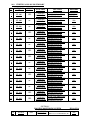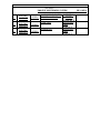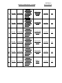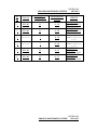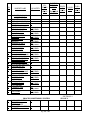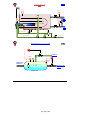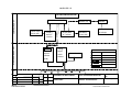
1
OIL INDIA LIMITED
(A Government of India Enterprises)
PO : Duliajan – 786602
Assam (India)
TELEPHONE NO. 91-33 22301657/59
FAX NO: 91 33 22302596
Email: [email protected] ; [email protected]
FORWARDING LETTER
Tender No.
: SKI0407P14
Tender Fee
: Rs 1,000.00
Bid Security Amount
: Rs. 1,64,250.00
Bidding Type
: SINGLE STAGE TWO BID SYSTEM
Bid Closing on
: As mentioned in the e-portal
Bid Opening on
: As mentioned in the e-portal
Performance Security
: Applicable
Integrity Pact
: Applicable
Date of pre-bid conference :
Date 04.07.2013
29.08.2013 & 30.08.2013
Venue of pre-bid conference : GUWAHATI, ASSAM.
OIL invites Bids for UP-GRADATION & AUGEMENTATION OF PROCESS
MONITORING SYSTEM FOR MAKUM OCS through its e-Procurement site under
SINGLE STAGE TWO BID SYSTEM. The bidding documents and other terms and conditions are
available at Booklet No. MM/CALCUTTA/E-01/2010. The prescribed Bid Forms for submission of
bids are available in the Technical RFx -> External Area - > Tender Documents .
The general details of tender can be viewed by opening the RFx [ Tender] under RFx and Auctions..
The details of items tendered can be found in the Item Data and details uploaded under Technical
RFX.
Note:(1) A Pre-Bid Conference with the Parties will be held in Guwahati (India) on 29.08.2013
& 30.08.2013 to discuss on the technical specifications and other terms and conditions
of the tender. All the Parties who purchase the Tender Document (User ID and
Password) within the Last date of Tender Fee Payment i.e. 14.08.2013 (or amended
otherwise) will be eligible to attend the Pre-Bid Conference. The exact venue and time
of the Pre-Bid conference will be intimated to the Parties at a later date.
(2) Clarification on the technical specifications and other terms & conditions of the tender
shall be provided to the parties during the Pre-bid Conference. Parties should come fully
prepared to the Pre-bid Conference and submit their queries to OIL in the Pre-bid
Conference for clarification. The set of queries may also be sent to OIL at least 7 (seven)
days before the Pre-bid Conference for study by OIL. At the most 2 (Two) representatives
from each party shall be allowed to participate in the pre-bid conference. All costs for
attending the pre-bid conference shall be to the bidder’s account.
(3) Any changes in the technical specifications and other terms & conditions of the tender
arising out of discussion in the Pre -bid Conference shall also form part of the tender
document.
(4) Parties, immediately after the USER ID AND PASSWORD, shall inform OIL at the
following address about their participation in the Pre-Bid Conference with details of the
persons to enable OIL to make arrangement for the Pre-Bid Conference.
Head-Calcutta Branch,
Oil India Limited,
4, India Exchange Place,
Kolkata – 700 001.
TELEPHONE NO. (033) 222301657
FAX NO: (033) 22302596
Email: [email protected];[email protected]
The tender will be governed by:
a)
“General Terms & Conditions” for e-Procurement as per Booklet No. MM/CALCUTTA/E01/2010 for E-Procurement LCB Tenders and Amendment No. 1 to General Terms and
Conditions for Indigenous E-Tender.
b)
Technical specifications and Quantity as per Annexure – 1I and following tender
documents.
1) Detailed technical specification
2) P&I diagram for each equipement with Tag numbers are attached as ppt.
3)EXISTING CONTROL ROOM LAYOUT.
4)EXISTING SYSTEM CONFIGURATION
c)
The prescribed Bid Forms for submission of bids are available in the Technical RFx ->
External Area - > Tender Documents.
d)
In the event of receipt of only a single offer against the tender within B.C. date, OIL reserves
the right to extend the B.C. date as deemed fit by the Company. During the extended period, the
bidders who have already submitted the bids on or before the original B.C. date, shall not be
permitted to revise their quotation.
e)
Any sum of money due and payable to the contractor (including Security Deposit
refundable to them) under this or any other contract may be appropriated by Oil India Limited
and set-off against any claim of Oil India Limited (or such other person or persons contracting
through Oil India Limited) for payment of sum of money arising out of this contract or under
any other contract made by the contractor with Oil India Limited (or such other person or
persons contracting through Oil India Limited).
f)
Bidder are advised to fill up the Technical bid check list and Response sheet given in MS
excel format in Technical RFx -> External Area - > Tender Documents. The above filled up
document to be uploaded in the Technical RFX Response.
Special Note:
1.0 General Qualification Criteria:
In addition to the general BRC/BEC, following criteria on Bidders' Experience and their financial
capabilities shall be considered (documentary evidence to be provided along with the bid in
Technical RFx -> External Area - > Tender Documents) as on the Bid Closing Date:
a) Bidder should have experience of successfully executing similar order of Rs.49.27Lakhs during
last 3 years.
b) Annual financial turnover of the firm in any of the last 3 financial years or current financial year
should not be less than Rs. 1.64 CRORES.
2.0 Application showing full address / e-mail address with Tender fee (non-refundable) of ` 1000.00
per tender (excepting PSU and SSI units registered with NSIC) by Demand Draft in favour of M/s. Oil
India Limited payable at Kolkata and to be sent to Head-Calcutta Branch, Oil India Limited, 4, India
Exchange Place, Kolkata – 700 001. Application shall be accepted only upto 14.08.2013 (or as amended
in e-portal).The envelope containing the application for participation should clearly indicate
““REQUEST FOR ISSUE OF USER ID AND PASSWORD FOR E TENDER NO SKI9952P14 for
easy identification and timely issue of authorisation. On receipt of requisite tender fee and subject to
fulfilment of eligibility criteria, USER_ID and initial PASSWORD will be communicated to the bidder
(through-e-mail) and will be allowed to participate in the tender through OIL’s e-Procurement portal.
No physical tender documents will be provided. USER_ID AND INITIAL PASSWORD WILL BE
ISSUED TILL 15.08.2013
3.0 The tender is invited under SINGLE STAGE-TWO BID SYSTEM. The bidders are required
to submit both the “TECHNO-COMMERCIAL UNPRICED BID” and “PRICED BID”
through electronic format in the OIL’s e-Tender portal within the Bid Closing Date and Time
stipulated in the e-Tender.
3.1
Please ensure that Technical Bid / all technical related documents related to the tender
are uploaded in the Technical RFx Response-> User - > Technical Bid only. The “TECHNOCOMMERCIAL UNPRICED BID” shall contain all techno-commercial details except the prices.
Please note that no price details should be uploaded in Technical RFx Response.
3.2
The “PRICE BID” must contain the price schedule and the bidder’s commercial terms and
conditions.The prices of the items should be quoted in “Conditions Tab”. The prices of the
items should be quoted in “Conditions Tab”. Details of prices as per Bid format / Commercial
bid can be uploaded as Attachment under the attachment option under “Notes &
Attachments”
3.3
A screen shot in this regard is given below. Offer not complying with above submission
procedure will be rejected as per Bid Rejection Criteria .
Go to this Tab “Technical RFx
Response” for Uploading “Technocommercial Unpriced Bid”.
Go to this Tab “Notes and
Attachments” for Uploading
“Priced Bid” files.
On “EDIT” Mode- The following screen will appear. Bidders are advised to Upload “TechnoCommercial Unpriced Bid” and “Priced Bid” in the places as indicated above:
Bid on “EDIT” Mode
Area for uploading TechnoCommercial Unpriced Bid*
Area for uploading Priced
Bid**
Note :
* The “Techno-Commercial Unpriced Bid” shall contain all techno-commercial details except the
prices.
** The “Price bid” must contain the price schedule and the bidder’s commercial terms and
conditions. For uploading Price Bid, first click on Sign Attachment, a browser window will open,
select the file from the PC and click on Sign to sign the Sign. On Signing a new file with extension
.SSIG will be created. Close that window. Next click on Add Atachment, a browser window will
open, select the .SSIG signed file from the PC and name the file under Description, Assigned to
General Data and clock on OK to save the File.
4.0 Please note that all tender forms and supporting documents are to be submitted through OIL’s eProcurement site only except following documents which are to be submitted manually in sealed
envelope super scribed with Tender no. and Due date to Head-Calcutta Branch, Oil India Limited,
4, India Exchange Place, Kolkata – 700 001 only on or before the Bid Closing Date and Time
mentioned in the Tender.
a) Original Bid Security
b) Detailed Catalogue (if any)
c) Any other document required to be submitted in original as per tender requirement
All documents submitted in physical form should be signed on all pages by the authorised signatory of
the bidder and to be submitted in triplicate
5.0 Bidders are requested to examine all instructions, forms, terms and specifications in the bid.
Failure to furnish all information required as per the NIT or submission of offers not
substantially responsive to the bid in every respect will be at the bidders risk and may result in
rejection of its offer without seeking any clarifications.
6.0 All the Bids must be Digitally Signed using “Class 3” digital certificate with Organisation’s
name (e-commerce application) as per Indian IT Act obtained from the licensed Certifying
Authorities operating under the Root Certifying Authority of India (RCAI), Controller of
Certifying Authorities (CCA) of India. The bid signed using other than “Class 3 with
Organisation’s Name” digital certificate, will be rejected.
7.0 Bidders must ensure that their bid is uploaded in the system before the tender closing date and
time. Also, they must ensure that above documents which are to be submitted in a sealed
envelope are also submitted at the above mentioned address before the bid closing date and time
failing which the offer shall be rejected.
8.0 Bid must be submitted electronically only through OIL’s e-procurement portal. Bid submitted in
any other form will be rejected.
9.0 SINGLE STAGE TWO BID SYSTEM shall be followed for this tender and only the PRICEDBIDS of the bidders whose offers are commercially and technically acceptable shall be opened
for further evaluation.
10.0 a) The Integrity Pact is applicable against this tender. OIL shall be entering into an
Integrity Pact with the bidders as per format enclosed vide Annexure-V of the tender
document. This Integrity Pact proforma has been duly signed digitally by OIL’s competent
signatory. The proforma has to be returned by the bidder (along with the technical bid)
duly signed (digitally) by the same signatory who signed the bid, i.e., who is duly authorized
to sign the bid. Any bid not accompanied by Integrity Pact Proforma duly signed (digitally)
by the bidder shall be rejected straightway. Uploading the Integrity Pact with digital
signature will be construed that all pages of the Integrity Pact has been signed by the
bidder’s authorized signatory who sign the Bid.
b) The name of the OIL’s Independent External Monitors at present are as under:
i)
SHRI N. GOPLASWAMI, I.A.S. (Retd.),
Former Chief Election Commissioner of India
E-mail Id : [email protected]
ii)
SHRI RAMESH CHANDRA AGARWAL, IPS (Retd.)
Former Director General of Police
E-mail Id : [email protected]
13.0 The tender shall be governed by the Bid Rejection & Bid Evaluation Criteria given in enclosed
Annexure-II. However, if any of the Clauses of the Bid Rejection Criteria / Bid Evaluation Criteria
contradict the Clauses of the tender and / or “General Terms & Conditions” as per Booklet No.
MM/CALCUTTA/E-01/2010 for E procurement (LCB Tenders) to General Terms and Conditions
for Indigenous E-Tender elsewhere, those in the BEC / BRC shall prevail.
14.0
To ascertain the substantial responsiveness of the bid OIL reserves the right to ask the bidder
for clarification in respect of clauses covered under BRC also and such clarifications fulfilling
the BRC clauses in to must be received on or before the deadline given by the company, failing
which the offer will be summarily rejected.
15.0
Please do refer the User Manual provided on the portal on the procedure How to create
Response for submitting offer.
NOTE:
1. Bidders should submit their bids explicitly mentioning compliance / non compliance to all
the NIT terms and conditions.
Yours Faithfully
(B BHARALI)
SENIOR PURCHASE OFFICER
FOR HEAD-CALCUTTA BRANCH
OIL INDIA LTD. KOLKATA
OIL INDIA LIMITED
(A Government of India Enterprise)
4, India Exchange Place, 4th floor,
Kolkata 700001,
West Bengal (India)
TELEPHONE NO. (033) 2230 1657 / 58 / 59
FAX NO: (91-033) 2230 2596
Email : [email protected]
[email protected]
ANNEXURE-II
Tender no. SKI0407P14 Dated: 04.07.2013
OIL INDIA LIMITED invites Indigenous tenders for items detailed below:
TECHNICAL SPECIFICATIONS WITH QUANTITY
SLNO
MATERIAL DESCRIPTION.
QUANTITY
UNIT
&
MATERIAL
CODE NO.
10
-----------0C000334
UP-GRADATION &
AUGEMENTATION OF PROCESS
MONITORING SYSTEM FOR
MAKUM OCS.
01
No.
The tender consist of following documents
1) Detailed technical specification (Refer
Annexure II-A)
2) P&I diagram for each equipment with
Tag numbers are attached as ppt. (Refer
Annexure II-B)
3)EXISTING CONTROL ROOM
LAYOUT. (Refer Annexure II-C)
4)EXISTING SYSTEM
CONFIGURATION. (Refer Annexure II-D)
20
------------
Installation & Commissioning
01
AU
I)BID REJECTION CRITERIA (BRC)
The following BRC/BEC will govern the evaluation of the bids received against this tender.
Bids that do not comply with stipulated BRC/BEC in full will be treated as non responsive and
such bids shall prima-facie be rejected. Bid evaluation will be done only for those bids that pass
through the “Bid Rejection Criteria” as stipulated in this document.
Other terms and conditions of the enquiry shall be as per General Terms and Conditions vide
MM/CALCUTTA/E-01/2010 for E-Procurement LCB Tenders. However, if any of the Clauses
of the Bid Rejection Criteria / Bid Evaluation Criteria (BRC / BEC) contradict the Clauses of
the tender or MM/CALCUTTA/E-01/2010 elsewhere, those in the BRC / BEC shall prevail.
(A)
TECHNICAL :
1.1. BIDDERS must be in the relevant business of supply of Data acquisition and Control systems
(DCS/PLC) and Oil field Instruments for a period of at least last 5 (five) years preceding from
the Bid Closing date. BIDDERS are required to produce documentary evidence for the same
in the prescribed format as given in Section E-4.
1.2. At least TWO (2) Nos. installations of similar system offered by the BIDDER should have
been engineered by the SUPPLIER or his principal and in continuous operation for a period of
at least two years from the Bid Closing date. Out of the two mentioned system one system
must be of minimum value of Rs.49.27Lakhs.Documentary evidence to support the same to
be produced.
Note: Similar system stands for up-grade/augmentation jobs related to process control
instrumentation using DCS/PLC systems in oil & gas industries.
1.3. The SUCCESSFUL BIDDER will be required to submit DGMS (Director General of Mines
safety), Dhanbad, India’s valid approval certificate for all the field instruments (as per para 7.3
of Section C) along with supply. Bidders are required to confirm in writing in their bid for
submission of the same along with the supply in the event of an order on them.
1.4. The BIDDER shall furnish along with the bid, the information called for in CHECK LIST
(Section E2), Data sheets (Section D) and various schedules in section E in the prescribed
format only, failing which the bid will be considered incomplete and OIL INDIA LIMITED
(OIL) reserves the right to reject the bid.
1.5. The bid shall be in accordance with the specification and shall be complete in all respects. The
bidder shall clearly indicate in his offer the list of deviations on a separate sheet (refer section
E-3) even though these may be mentioned somewhere else in the quotation.
1.6. The SUPPLIERS are required to forward system configuration details with interconnection
diagrams, equipment layout diagram in the field & control room and detailed technical
literature of each equipment/system along with the quotation; otherwise the offers will be
rejected.
B) COMMERCIAL:
1.
Bidders are required to submit their offer under Single stage “Two Bid System”. Bidders have to submit both
the “Techno-commercial Unpriced Bids” and “Priced Bids” through electronic form in the OIL’s e-Tender
portal within the bid Closing date and time stipulated in the e-tender. The Techno-commercial Unpriced bid is
to be submitted as per scope of works and Technical specification of the tender and the priced bid as per the
online Commercial bid format. For details of submission procedure, please refer relevant para of General Terms
and Conditions vide MM/CALCUTTA/E-01/2010 for E-Procurement LCB Tenders. Any offer not complying
with the above mentioned procedure, will be rejected straightway.
a. Bid Security :
Bid security of Rs 1,64,250
1,64,250.00
250.00 (Rupees One Lakh sixty four thousand two hundred fifty)
only shall be submitted manually in sealed envelope superscribed with Tender no. and Bid
Closing date to HEAD-CALCUTTA BRANCH, Oil India Limited, 4, India Exchange Place,
Kolkata - 700001 on or before the Bid Closing Date and Time mentioned in the Tender. If
bid security in ORIGINAL of above mentioned amount is not received within bid closing
date and time, the bid submitted through electronic form will be rejected without any further
consideration. For exemption for submission of Bid Security, please refer relevant Clause of
General Terms and Conditions vide MM/CALCUTTA/E-01/2010 for E-Procurement LCB
Tenders. The Bid Security shall be valid for 10 months (date shall be put during
tendering) from the date of bid opening.
b. Performance Bank Guarantee:
Successful bidder will be required to furnish a Performance Bank Guarantee @10% of the
order value. For exemption for submission of Performance Bank Guarantee, please refer
relevant Clause of MM/CALCUTTA/E-01/2010. Performance Bank Guarantee shall be
valid for 12 months from the date of commissioning or 18 months from the date of despatch
whichever concludes earlier.
c. The Bank Guarantee should be allowed to be encashed at all branches within India.
d. Validity of the bid shall be minimum 120 days from the Bid Closing Date. Bids without minimum validity
shall be rejected.
e. The prices offered will have to be firm through delivery and not subject to variation on any account. A bid
submitted with an adjustable price will be treated as non-responsive and rejected.
f. Bids received after the bid closing date and time will be rejected. Similarly, modifications to bids received after
the bid closing date & time will not be considered.
g. All the Bids must be Digitally Signed using “Class 3” digital certificate (e-commerce application) as per Indian
IT Act obtained from the licensed Certifying Authorities operating under the Root Certifying Authority of
India (RCAI), Controller of Certifying Authorities (CCA) of India. The bid signed using other than “Class 3”
digital certificate, will be rejected.
h. Technical RFx Response folder is meant for Technical bid only. Therefore, No price should
be given in Technical RFx Response folder, otherwise the offer will be rejected.
i. Price should be maintained in the “online price schedule” only. The price submitted other than the “online price
schedule” shall not be considered.
vii)
INTEGRITY PACT:
OIL shall be entering into an Integrity Pact with the bidders as per format enclosed vide Annexure V of the tender
document. This Integrity Pact proforma has been duly signed digitally by OIL's competent signatory. The proforma has
to be returned by the bidder (along with the technical bid) duly signed (digitally) by the same signatory who signed the
bid, i.e., who is duly authorized to sign the bid. Any bid not accompanied by Integrity Pact Proforma duly signed
(digitally) by the bidder shall be rejected straightway. Uploading the Integrity Pact with digital signature will be
construed that all pages of the Integrity Pact has been signed by the bidder's authorized signatory who sign the Bid.
The names of the OIL’s Independent External Monitors at present are as under:
i.
SHRI N. GOPLASWAMI, I.A.S. (Retd.),
Former Chief Election Commissioner of India
E-mail Id: [email protected]
ii.
SHRI RAMESH CHANDRA AGARWAL, IPS (Retd.)
Former Director General of Police
E-mail Id: [email protected]
2.
Payment : Payment shall be made to the supplier as follows :
a. 70% of the cost of the equipment shall be paid against dispatch documents of the main
equipment provided the DGMS approval copy for all field instruments are provided
along with the dispatch documents. The DGMS approval copy has to be valid for a
period of minimum six months from the date of dispatch of the respective item. If any
item is dispatched with DGMS field trail permission copy then only 50% payment with
respect to value of that item will be released on delivery of that item and the remaining
amount will be paid only after providing the valid DGMS approval against that
particular item. ****
b. Balance 30% of the equipment cost along with the commissioning charges shall be paid
after successful commissioning of the entire equipment.
Notes (****):
i.
Materials where DGMS approval is required, payment to the extent of 50% of the material
cost will be released on proof of dispatch alongwith the proof of submission of DGMS Field
Trial, if valid DGMS approval is not submitted along with bid or during Inspection for
dispatch clearance.
ii.
Balance 50% of material value along with the installation and commissioning charges, if any,
to be released only after successful commissioning and after obtaining DGMS Certificate of the
equipment. A system will be considered as successfully commissioned only after obtaining
valid DGMS approval for all the constituent equipment/instruments of the system.
Offers not complying with the above shall be rejected.
(II)
BID EVALUATION CRITERIA (BEC) :
The bids conforming to the technical specifications, terms and conditions stipulated in the
tender and considered to be responsive after subjecting to the Bid Rejection Criteria as well
as verification of original of any or all documents/ documentary evidences pertaining to BRC
will be considered for further evaluation as per the Bid Evaluation Criteria given below.
(A)
TECHNICAL :
1. All materials as indicated in the tender should be offered. If any of the items not offered
by the bidder, the offer will not be considered for evaluation.
(B)
COMMERCIAL :
a.
To evaluate the inter-se-ranking of the offers, Assam Entry Tax on purchase value will be loaded as
per prevailing Govt. of Assam guidelines as applicable on bid closing date. Bidders may check this
with the appropriate authority while submitting their offer.
b.
In the event of computational error between the unit price and total price, unit price shall prevail for
evaluation.
c.
Similarly in the event of discrepancy between the words and figure, words shall prevail and adopted
for evaluation.
d.
To ascertain the substantial responsiveness of the bid OIL reserves the right to ask the bidder for
clarification in respect of clauses covered under BRC also and such clarifications fulfilling the BRC
clauses in toto must be received on or before the deadline given by the company, failing which the
offer will be summarily rejected.
e.
Priced bids of only those bidders will be opened whose offers are found technically acceptable. The
technically acceptable bidders will be informed before opening of the "priced bid".
Annexure II-A
TENDER NO.SKI0407P14 Dated 04.07.2013.
UP-GRADATION & AUGEMENTATION OF PROCESS MONITORING
SYSTEM FOR MAKUM OCS
(Instrumentation, Control & Data acquisition system)
CONTENTS
SECTION
SUBJECT
NO. OF SHEETS
A1
SCOPE OF ENQUIRY
2
A2
INSTRUCTIONS TO BIDDERS
3
B1
PROJECT INFORMATION
- GENERAL
1
B2
PROJECT INFORMATION
- PROCESS DETAILS
8
C
SCOPE OF SUPPLY
D
D1
D2
D3
D4
DATA SHEETS
SOFTWARE
CONTROL SYSTEM
OS/ES/ROS
DIAPHRAGM SEALED PRESSURE
TRANSMITTER
PRESSURE TRANSMITTER
TEMPERATURE TRANSMITTER WITH RTD
FLAME SCANNER
RADAR TANK GAUGE
LEVEL & INTERFACE TRANSMITTER
LEVEL TRANSMITTER
WATER IN OIL MONITOR
I/P CONVERTERS
PRESSURE SWITCHES
CONTROL CABLE
CABLE TRAYS
CONTROL CABINETS
LCD PANEL
MULTIWAY JUNCTION BOXES
DUAL UPS
D5
D6
D7
D8
D9
D10
D11
D12
D13
D14
D15
D16
D17
D18
D19
E1
E2
E3
E4
E5
F1
38
SCHEDULE OF PRICES
CHECK LIST
SCHEDULE OF DEVIATIONS FROM
TECHNICAL SPECIFICATIONS
SUPPLIER’S EXPERIENCE
SCHEDULE OF RECOMMENDED SPARES &
SERVICE CONTRACT OFFER
3
6
1
4
3
3
1
1
1
3
2
2
2
2
1
1
1
1
1
4
3
1
1
1
BID EVALUATION/ REJECTION
CRITERIA(Refer Annexure II)
SECTION A1
PROCESS MONITORING SYSTEM
SH 1 OF 2
0.0
SCOPE OF ENQUIRY
0.1
This procurement specification covers design engineering, manufacture, testing at
SUPPLIER’S works, packing, supply, transportation from place of manufacture to site,
complete erection, and site testing after erection, startup, commissioning and performance
testing of the Instrumentation, control & Data acquisition system.
The above Instrumentation, Control & Data Acquisition system package is required for
Makum OCS to meet the additional requirement of process instruments against capacity
augmentation of the OCS and also to up-grade/replace the existing control system with a
new one. The term up-grade stands for upgrading the existing control system supplied by
M/s Yogakawa, Model: Stardom with a suitable, latest and higher version of process
controller from M/s Yogakawa, s current product line which is proven and established across
the oil & gas sector operations worldwide. The term replacement stands for replacing the
0.2
existing control system supplied by M/s Yogakawa, Model: Stardom with a suitable latest
control system configuration of any make where the presently connected I/O’s in the existing
system will be seamlessly hooked up with the new system in addition to the new I/O’s that
will be supplied as a part of this project. Bidder will also have to carry out the software
configuration of existing open and closed process control loops that are in operation with the
present control system. The scope will also include reconfiguration and redesign cum loop
tuning of the existing closed loop PID control loops that are already running with the present
control system. Preliminary list of all existing loops is attached with this tender and other
details will be provided by us during detail engineering process.
The new process monitoring system shall be capable of monitoring and control of all process
parameter including the existing and additional.
This procurement specification also covers integration of the existing field Instruments and
existing control room instruments (if any) that were commissioned with Yokagawa, STAR
DOM System. List of such control room equipments/systems will be provided by us during
detail engineering stage.
This procurement specification also covers integration of the Instruments/Systems that are
supplied by other suppliers (specified herein) in close liaison with them. Bidder will have to
integrate the existing standalone systems with the offered system through
MODBUS/Ethernet communication for alarm and process data sharing on a single platform.
0.3
0.4
0.5
SECTION A1
PROCESS MONITORING SYSTEM
•
•
SH 2 OF 2
The following two systems located in the control room needs to be integrated with the
proposed system:
PLC based system of M/s Allen Bradley, Model: FlexLogix, Catalogue no.1794-l34B
M/s Emerson make Micro-motion 3700 series corillossis
mass flow meter transmitter.
Details about the two systems will be provided by us during detail engineering stage.
0.6
0.7
0.8
Bidder will also have to provide a 51inch LCD display panel apart from the usual ES & OS
and remote OS, which will be wall mounted in the control room for display of all process
parameters, alarms, trends, graphics, plant overview in the form of P&ID, PFD etc. The
alarms should be able to be acknowledged through soft interface as well as hard wired pushbuttons mounted in the console/panel.
Bidder will have to dismantle, remove & isolate the existing control room marshalling
panels, ES, OS, MIMIC panel and other associated components of the old system for
installing the new system components to be supplied as a part of the up-grade project.
Bidder will have to employ process control specialists for converting the existing
pneumatically controlled PID loops to electronic fully automatic closed loop PID
control schemes including loop configuration and tuning as per the process control
philosophy of the Oil Collecting station. Also the closed loop control scheme of the OCS
must be fail safe type and under extreme case of system/power/servo/air failure the
controllers must be configured to bring the process to a safe state. Bidder must consider
in their bid any additional instruments/system that will be required to achieve the
above control philosophy. P&ID, P&FD, Set-points, vessel operating condition and
other process details will be provided by us as per bidder requirement during detail
engineering stage. All the closed loops controls will be tested under different process
conditions for a period of minimum seven days after the configured system is handed
over to OIL. Satisfactory Performance of these closed loops and complete testing of failsafe control scheme will determine the final commissioning of the upgraded control
system.
PROCESS MONITORING SYSTEM
SECTION A2
SH 1 OF 3
1.0
INSTRUCTIONS TO BIDDERS
1.1
BIDDERS (SUPPLIERS) are required to submit their offer under
“Two Bid System”. BIDDERS (SUPPLIERS) are required to submit
the Technical bid and Price bid separately as per the
instruction given in the forwarding letter / supplier guide
documents . Technical bid shall contain strictly unpriced part
of the Bid only. Price bids of the technically acceptable
bidders shall only be opened in due course of time. Any offer
not meeting this criterion shall be rejected out rightly.
1.2
The BIDDER (SUPPLIER) shall furnish along with the bid, the information called for in
CHECK LIST (Section E2), Data sheets (Section D) and various schedules in section E in the
prescribed format only, failing which the bid will be considered incomplete and OIL INDIA
LIMITED (OIL) reserves the right to reject the bid.
1.3
The bid shall be in accordance with the specification and shall be complete in all respects.
The bidder shall clearly indicate in his offer the list of deviations on a separate sheet (refer
section E-3) even though these may be mentioned somewhere else in the quotation.
1.4
The BIDDER (SUPPLIER) shall clearly indicate in his bid that the prices quoted by them are
firm.
1.5
All tools, tackles and equipments required for commissioning and carrying out tests should
be arranged by the BIDDER (SUPPLIER).
1.6
BIDDER (SUPPLIER) is advised to inspect the site at their own cost and examine and
obtain all information required and satisfy himself regarding all matters such as access to site,
areas likely to be allotted to him for his storage yard and for his site works, transport and
facilities required for the satisfactory completion of work and also the detail
instrument/system requirements to complete the up-gradation cum augmentation job
including instrument hook-up options/schemes/provisions available etc as per the scope
of the tender. Ignorance of site conditions shall not be accepted as basis for any claim for
compensation. The submission of Tender by BIDDER (SUPPLIER) will be construed as
evidence that such an examination was made and any later claims/ disputes in regard to price
quoted shall not be entertained by OIL INDIA LIMITED (OIL).
PROCESS MONITORING SYSTEM
SECTION A2
SH 2 OF 3
1.7
BIDDER (SUPPLIER) shall furnish along with his bid the list of manufactured items, along
with the manufacturer’s name that are proposed to be used in this contract. The
BIDDER(SUPPLIER) shall provide detailed technical literature of each equipment to be
supplied along with the BID without which the offer is likely to be rejected.
1.8
Within TWO (2) weeks from the date of receipt of Letter of Intent the successful BIDDER
(SUPPLIER) shall submit the first set of drawings for the approval of OIL INDIA LIMITED
(OIL). The drawings will normally be commented upon approved and dispatched within
TWO (2) weeks of their receipt by OIL INDIA LIMITED (OIL). No claim, however, shall be
entertained due to any delay in the approval of the BIDDER (SUPPLIER)’S drawings.
1.9
The BIDDER (SUPPLIER) shall separately indicate prices for recommended spare parts (for
2 years of operation) and Service contract offer as called for in section E-5.
1.10
The BIDDER shall be confirm that all the spare part of their offered system will be available
for at least ten(10) years from date of supply.
1.11
As a part of scope of services, the successful BIDDER (SUPPLIER) shall impart
comprehensive training to OIL INDIA LIMITED (OIL) personnel covering the salient
features as required for proper operation and maintenance of the complete system.
2.0
DELIVERY
The SUPPLIER shall complete design, manufacture and supply of the PROCESS
MONITORING SYSTEM as specified complete with all accessories within 16 weeks from
the date of issue of Letter of Intent (LOI) or placement of order, whichever is earlier. The
erection, testing and commissioning of the system at site shall be completed within 8 weeks
time.
3.0
LIQUIDATED DAMAGES
3.1
Delivery period shall be guaranteed. In case of delays, the SUPPLIER shall be liable to pay
by the way of liquidated damages of 0.5% of the value of the order for each weeks (or part
there of) delay beyond the agreed date(s) mentioned in Purchase Order, subject to a
maximum of 7.5% of order value.
PROCESS MONITORING SYSTEM
4.0
PERFORMANCE BANK GUARANTEE
SECTION A2
SH 3 OF 3
4.1
Successful bidder shall be required to furnish a Performance
Bank Guarantee @10% of the cost of the materials. The
Performance Bank Guarantee must be valid for one year from the
date of successful commissioning of the equipment to cover the
entire warranty period. Offers not complying with this clause
shall be rejected.
PROCESS MONITORING SYSTEM
1.0
PROJECT INFORMATION – GENERAL
1.1
Owner/ Purchaser
:
OIL INDIA LIMITED
SECTION B1
SH 1 OF 1
1.2
Project Title: Up-gradation & Augmentation of PROCESS MONITORING
SYSTEM for MAKUM OIL COLLECTING
STATION
1.3
location
1.4
Nearest Railway station
:
Tinsukia, Assam
1.5
Name of the Railway
:
North Frontier Railway
1.6
Nearest Highway
:
NH 37
1.7
Distance of nearest
Highway from site
:
3 Kms
1.8
Altitude above mean
Sea level
:
300 feet
1.9
Ambient air temperature
a) Maximum
b) Minimum
c) Average
a) Reference Temperature
For design of electronic
Equipment/ Devices
:
:
:
:
40.0 Deg. C
5.0 Deg. C
26.5 Deg. C
40.0 Deg. C
:
100% at 21 Deg. C
:
:
70% at 41 Deg. C
95% at 32 Deg. C
:
:
480 mm (in July)
27 mm (in November)
Wind Velocity
a) Basic Wind speed
b) Prevailing wind
Conditions (direction)
:
:
20 Km/hr
From east
Environment
:
Humid
1.10
1.11
:
Relative Humidity %
a) Maximum during
monsoon
b) Minimum
c) Average
Rainfall
a) Maximum
b) Minimum
Makum, Assam
It rains throughout the year.
1.12
1.13
PROCESS MONITORING SYSTEM
1.0 PROJECT INFORMATION – PROCESS DETAILS:
CRUDE OIL STORAGE
SECTION B2
SH 1 OF 8
1.1 MAKUM OCS FLOW SCHEMATIC
MANIFOLD
INDIRECT
HEATER
GROUP UNIT-II
GROUP UNIT-I
EET
STABILIZER
EMULSION
TREATERS
TO FLARE
TO LPB SUCTION
& FLARE
INDIRECT HEATER
TEST
HPMS
LPMS
LPM
S
TES
T
UNI
T
TO DISTRIBUTION
TEST
TANK
FWDP
CRUDE OIL
LINE
GAS LINE
WATER LINE
TO DISPOSAL WELL
FORMATION WATER
TANKS
SECTION B2
PROCESS MONITORING SYSTEM
1.2
PROCESS OF OIL COLLECTING STATION
SH 2 OF 8
The process in an OIL COLLECTING STATION comprises of a system for gathering
produced fluid from a number of oil wells and separation of the Crude oil, Natural Gas,
Water and other solid particles such as reservoir sands from the well fluid.
In order to achieve this, the well fluid is passed through a network of heaters, various
pressure vessels (separators) and there by knocking out the undesired water and stripping the
gas from the crude oil. The pressure staging of the vessels is so maintained with backpressure
controllers that an optimum separation of the oil and gas is achieved and separated gas is
utilized for end users. The separated crude is stored in fixed roof storage tanks and from there
pumped to the main trunk pipeline.
1.3
PROCESS VESSEL DETAILS
a)
HP MANIFOLD:
(M-101,M-101A,M-101B,M-101C)
Max. pressure of the Flow line
Max. operating pressure
Normal operating pressure
Operating temperature range
NOTE: MAXIMUM INDIVIUAL
MANIFOLD:210 Kg/Cm2
b)
:
:
:
:
WELL
75 kg/Cm2
25 Kg/Cm2
21 Kg/Cm2
10 – 500C
PRESSURE
CONNECTED
TO
HP
LP MANIFOLD:
(M-102,M-102A,M-102B)
Max. operating pressure
Normal operating pressure
Operating temperature range
:
:
:
10 Kg/Cm2
6 Kg/Cm2
10 – 500C
NOTE: MAXIMUM INDIVIUAL WELL PRESSURE CONNECTED TO LP MANIFOLD:
210 Kg/Cm2
c)
GROUP UNIT-I :
(V-101/GU-1, V-102/GU-2,V-117/GU-3,V-118/GU-4)
Vessel
Operating Pressure
Max. Pressure
Capacity
Dimensions
:
:
:
:
Horizontal, Pressurized
25 Kg/Cm2
37.5 Kg/Cm2
:
5000 BPD (oil)
Length(side to Side):4.57M
Dia.: 1.093 Mtr (height)
SECTION B2
PROCESS MONITORING SYSTEM
d)
GROUP UNIT-II
(V-103/GU-5, V-104/GU-6,V-119/GU-7,V-120/GU-8)
Vessel
Operating Pressure
:
:
Horizontal, Pressurized
7.0 Kg/Cm2
SH 3 OF 8
Max. Pressure
Capacity
Dimensions
e)
f)
g)
h)
:
:
12.8 Kg/Cm2
:
5000 BPD (oil)
L(S/S): 4.30M, Dia.: 1.40M
EMULSION TREATERS
(V-105/ET-1, V-106/ET-2,V-121/ET-3,V-122/ET-4)
Vessel
:
Horizontal, Pressurized
With Gas fired Heater
Operating Pressure
:
3.5 Kg/Cm2
Max. Pressure
:
5.0 Kg/Cm2
Capacity
:
5000 BPD (oil)
Operating Temp. range
:
60 – 700C
Burner details
:
2-Natural gas fired burners
of 1,000,000 BTU/Hr
capacities each
Dimensions
:
L (s/s): 9.25M,
Dia.: 2.0M (Height)
Body plate thickness: 8 mm
STABILIZERS
(V-107/STB-1, V-108/STB-2)
Vessel
:
Horizontal, Pressurized
Operating Pressure
:
1 Kg/Cm2
Max. Pressure
:
5.25 Kg/Cm2
Capacity
:
10,000 BPD (oil)
Dimensions
:
L(S/S):4.60M, Dia.:1.5M (height)
TEST UNIT-I
(V-109/TU-I)
Vessel
Operating Pressure
Max. Pressure
Operating Temperature
range
Capacity
Dimensions
Gas outlet line size :
:
:
:
:
4” NB
:
Vertical, Pressurized
21 Kg/Cm2
31.5 Kg/Cm2
10 – 500C
:
3000 BPD (oil)
Height: 4.0M, Dia.: 1.0M
TEST UNIT-II
(V-110/TU-II)
Vessel
Operating Pressure
Max. Pressure
Operating Temperature range :
Capacity
Dimensions
:
Vertical, Pressurized
:
2.0 Kg/Cm2
:
10 Kg/Cm2
2
10 – 50 C
:
3000 BPD (oil)
:
Height: 3.05M
Dia.: 1.085M
Gas outlet line size
:
6” NB
SECTION B2
PROCESS MONITORING SYSTEM
i)
HIGH PRESSURE MASTER SEPERATOR (HPMS)
(V-111/HPMS-1, V-112/HPMS-2)
Vessel
:
Vertical, Pressurized
SH 4 OF 8
Operating Pressure
Max. Pressure
Capacity
:
:
Dimensions
:
25 Kg/Cm2
37.5 Kg/Cm2
:
15 MMSCFD (Gas),
500 BPD (oil)
Height: 3.05M,
Dia.: 1.07M
j)
LOW PRESSURE MASTER SEPERATOR (LPMS)
(V-113/LPMS-I, V-114/LPMS-II, V-115/VLPMS)
Vessel
:
Vertical, Pressurized
Operating Pressure
:
2.0 Kg/Cm2
Max. Pressure
:
6.5 Kg/Cm2
Operating Temp. range
:
10 – 500C
Gas flow range
:
0.4 MMSCMD
Gas outlet line size
:
10” NB
Capacity
:
0.4 MMSCMD (GAS)
Dimensions
:
Height: 2.35M, Dia.: 1.20M
k)
SERVO TANK
(V-116/ST-1)
Vessel
:
Operating Pressure
:
Max. Pressure
:
Outlet Gas flow range
:
(Internal gas consumption of OCS)
l)
CRUDE OIL DESPATCH MANIFOLD
(X-101)
Operating Pressure
:
35 Kg/Cm2
Max. Pressure
:
70 Kg/Cm2
3
Outlet Crude oil flow range :
140 M /Hr
Water percentage range
of Crude oil
:
less than 0.5%
m) CRUDE OIL STORAGE TANK
(T-101, T-102,T-103,T-104,T-105,T-106)
Capacity
Dimensions
:
Operating Pressure
n)
Vertical, Pressurized
10 Kg/Cm2
15 Kg/Cm2
:
TEST TANK
(T-103/T-107)
Capacity
Dimensions
:
Operating Pressure
:
:
795KL
Height: 10.0M
Dia.: 10.67M
Atmospheric
:
1000 BBL (US)
Height: 4.87M,
Dia.: 6.55M
Atmospheric
SECTION B2
PROCESS MONITORING SYSTEM
o)
CRUDE OIL DESPATCH PUMPS
(P-104, P-105, P-106, P-107,P-108)
Capacity of each pump
:
60 KL/HOUR
SH 5 OF 8
Operating Pressure
Maximum Pressure
Prime mover
:
:
:
35 Kg/Cm2
70 Kg/Cm2
Gas Engine
p)
FORMATION WATER DISPOSAL PUMPS
(P-201, P-202, P-203)
Prime mover
:
Electric Motor
q)
SUMP WATER PUMPS
(P-301, P-302)
prime mover
:
Electric Motor
SECTION B2
PROCESS MONITORING SYSTEM
SH 6 OF 8
1.12
EXISTING PROCESS MONITORING SYSTEM:
The existing PMS system is STAR DOM System supplied by M/sYokogawa India Limited, Plot No:96 Electronic City Complex, Hosur
Road, Bangalore-560 100, India.
The configuration of EXISTING stardom system is as follows:
• Engineering station hosts the logic designer software and used to programme the
process logics using slandered IEC61131-3 programming, support with color printer.
• Operator station hosting Versatile Data Server (VDS) software acts as both HMI
&client. Operator station acts as an interface with the whole plant, helps monitoring
the process parameters, displaying the plant graphics support with dot matrix printer.
• A dual redundant FCN is configured with extended I/O racks& various I/O modules
located in the control cabinet. I/O is non redundant.
• Ethernet is the backbone of the whole communication net work with engineering
station, operator station & FCN.
1.12.1 The system Configuration:(Sketch enclosed)
1.12.2 The List of Existing Field Instrument:
Sl
Item
No.
Pressure Transmitter(PT)
1
Remarks
16
Supplier has to connect with new
system supplied by them
-do-
2
Diaphragm
Transmitter
3
Temp. Transmitter with RTD (TT)
4
Differential
Pressure 9
Transmitter (DPT))
RADAR Tank Level Gauge
5
-do-
6
Guided
Wave
Transmitter(LT)
Level 10
-do-
7
Guided Wave Inter-phase
Transmitter(ILT)
Level 2
-do-
8
Water in Oil Monitor
1
-do-
9
Pressure Switch with
Seal(flow switch)
Diaphragm 7
-do-
10
11
Current to Pneumatic (I/P) Converter
Pilot
Flame
monitor
Thermocouple
5
Seal
Qnty.
Pressure 23
RADAR
11
18
with 7
SECTION B2
PROCESS MONITORING SYSTEM
1.12.3 The List of Existing I/O’s:
Digital Input (DI):
27
Digital Output (DO):
56 for MIMIC DISPLAY
Analogue Input (AI):
75
Analogue Input for control (AIC): 20
-do-
-do-
-do-do-
SH 7 OF 8
Analogue Output for control (AOC): 20
1.12.4 The list of Existing control room equipments.
SlNo.
1
2
Item
Engineering Station
Operator Station
Qnty
1
1
Remarks
Supplier has to replace.
Supplier has to replace.
3
Redundent CPU
1+1
As per requirement
4
Laser Printer (B/W)
1
Supplier has to replace
2
Supplier has to replace
5
Control Cabinet
6
DC
Regulated
Supply, 24 VDC
7
Dual UPS, 5 KVA with 12 One
5KVA Supplier has to replace
Hour Battery Backup with UPS is in
lightning protection
Damaged
condition
Hardwired Mimic panel
1
Supplier has to replace
with LCD panel
8
1.13
Power
PROPOSED PROCESS MONITORING & Control SYSTEM
The proposed process monitoring & control system will monitor all the important parameters
like Pressure, Level, Flow, Water percentage etc., of the OIL COLLECTING STATION
(OCS) from the Control room and alert the operator for any abnormal process conditions
with audio & visual alarms. It will also control the process for the parameters mentioned in
the tender.
SECTION B2
PROCESS MONITORING SYSTEM
1.5
Supplier has to replace
SH 8 OF 8
P&I DIAGRAM
The existing P&I Diagram of MAKUM OCS where new equipments are not shown are
enclosed as SKETCH-I (SK.NO.INST/071). Pneumatic controllers are used at present for
controlling those closed loops which we plan to convert to electronic PID control through the
subject tender. The present Instrumentation under PROCESS MONITORING SYSTEM is
shown in DOTTED LINES. The proposed Instrumentation under the scope of this tender for
each additional/existing OCS equipment is shown separately with the new instrument tag
numbers.
1.6
THE LAYOUT DIAGRAM
The layout Diagram of MAKUM OCS indicating the layout of major process equipments is
enclosed as SKETCH-II
1.7
CONTROL ROOM
The existing CONTROL ROOM plan with existing control room equipments/systems of M/s
YBL is enclosed as SKETCH-III. The CONTROL ROOM is indicated as PROCESS
MONITORING CUM OPERATOR’S ROOM in the SKETCH.
PROCESS MONITORING SYSTEM
SECTION C
SH 1 OF 38
1.0
SYSTEM TO BE FURNISHED
1.1
This specification is for design engineering, manufacturing, 100% integrated testing at
SUPPLIER’S works, supply, packing, forwarding, delivery at site, erection, commissioning,
carrying out performance/ acceptance tests at site of the complete system as specified in
scope of supply in Para 2.0 below.
1.2
The plant shall be largely controlled from Central control room of size given in the enclosed
SKETCH-III. All the electronic cubicles and the operator control center shall be located in
control room, which shall be air-conditioned. Supply of Air-conditioners is not in bidder’s
scope.
2.0
SCOPE OF SUPPLY
2.1
Microprocessor based Control system(dual redundant)
Qty.
2.1.1 Supervisor station with 21”TFT & Key board
(Engineer’s console)
1
2.1.2 Operator station with 21”TFT & Key board
2
(Operator’s console)- Local OS & Remote OS
2.1.3 Communication link (Cable)
2.1.4
As required
Dual redundant Microprocessor based
controller With
Power supply module and communi
-cation module
As required
2.1.5 Input Modules (Analog and Digital)
(As per Clause Nos 16.0 & 17.0
of Section C)- for existing + new
As required
2.1.6 Output Modules (Analog and Digital)
(As per Clause Nos 18.0 & 19.0
of Section C) )- for existing + new
As required
2.1.7 Data acquisition system
As required
2.2
Field Instruments
(As per details provided in
Section D4 to D14)
As mentioned
here in
2.3
51” LCD/Plasma Display
2.4
1 No.
Printers (Inkjet Colour Printer -1
Inkjet B&W Printer-1)
2 Nos
SECTION C
SH 2 OF 38
PROCESS MONITORING SYSTEM
*** Note: In case of LCD display panel the requirement of digital output cards will be
eliminated as the panel can communicate with the processor/server via Ethernet/serial
communication media.
2.5
2.6
5KVA Dual redundant UPS(Uninterrupted
Power supply) with 12-hours battery
Back-up.
1 Set(2 Nos)
DC power supply for
field Instruments
with Diode”O”ring
2 No in redundant mode
2.7
Zener Barriers
2.8
Laptop computer (programming device)
As required
1 No
2.9
Erection Work
2.9.1
Instruments to be supplied by SUPPLIER
2.9.2
Integration of the existing Instruments with new system supplied by SUPPLIER – as
per existing I/O list.
2.10
Supply of Erection Hardware like
Globe/ Needle valves, Impulse tube/
elbows, union, tee, 2” stand
pipes etc.(As per the Installation
sketches 1, 2, 3 & 4 enclosed)
As required
2.11
2.12
Termination Cabinet
Control system cabinet to mount
controller, I/O, Power supply
modules etc.
As required
As required
2.13
Prefabricated cable to connect
As required
Cabinets, ES, OS, TFT, LCD/Plasma display
2.14
2.15
Control cable to connect field
As required
Instruments to Termination Cabinet
And Termination cabinet to Field
Control devices
(As per the details provided in
Section D15)
Cable trays
(As per details provided in
Section D16)
PROCESS MONITORING SYSTEM
3.0
As required
SECTION C
SH 3 OF 38
TECHNICAL REQUIREMENTS
3.1
Microprocessor based Control system
3.1.1 General
Microprocessor based control system shall achieve the functions of signal acquisition,
signal conditioning, indication, closed loop control, open loop control, alarm processing
and annunciation, calculation, data logging, trending, graphic display of process, issue of
management reports & self monitoring of system failures.
3.1.2 Hardware requirements
The Hardware shall consist of a minimum possible number of different modules.
Preferably the programs and fixed data shall be stored in EPROM. If this is not available,
all RAM’s within the digital control system have to be backed up by battery, so that in
case of power failure no program reloading shall be necessary. The system must have a
minimum spare capacity of at least 30% (measuring circuits, control loops etc.)for
future use of OIL.
3.1.3
Performance requirements
The system shall be designed and manufactured to meet the following performance
requirements.
-
-
Numerical outputs shall be reproducible to 0.1% of a known analog input at mid
scale reading
Resolution of minimum 10 bits plus sign bit
Calculations, square root extractions and other computations shall be accurate to +1
to –1 (last digit)
Linearity shall be within 0.2% of all inputs
For analog inputs, input impedance shall be less than 10 ohms for current inputs and
greater than 1 Mega Ohm for Voltage inputs. Any input shall withstand a steady
signal of 24V or 10 times normal input which ever is greater. Each input shall be
fused against any greater overload. Overload of any channel shall not affect any other
channel. Channel to channel isolation shall exceed 10 mega ohms.
Channel selection shall be programmable
3.1.4 PROCESSOR
In case of CPU complete backup with automatic changeover has to be provided to take
over control automatically in the event of failure of operating Processor.
3.1.5 Signal input and output processing
In order to ensure a high availability, the Hardware shall be functionally distributed,
i.e., a limited number of inputs and outputs per module so that any failure shall have
limited effect. The analog signal input cards shall be able to accept mA signals and
voltage signals from the
PROCESS MONITORING SYSTEM
SECTION C
SH 4 OF 38
field transmitters of SMART & 2-wire type. Conversion in to engineering units by
calibration and linearization of the signals shall be possible. For long time stability of
calibration, automatic periodical test measurement and recalibration for zero and full
range shall be incorporated.
Filters to eliminate ripples and disturbances normally expected in the field shall be
provided.
The Digital input cards shall be able to supervise the circuit integrity and the
antivalence of Digital signal contacts and they shall ensure that the current through the
closed contacts shall be at least 3 ma, and the voltage at the open contacts shall be
potentially free.
The outputs of analog and digital output cards shall be short circuit proof.
All the field Transmitters/ sensors/ switches/
I/P converters shall be connected to
the Control system through suitable ZENER BARRIERS of MTL/P&F make.
3.1.6 CLOSED LOOP CONTROL
Besides the modulating control function PID, the controllers shall contain facilities for
bump less balance less transfer, auto/manual switching, cascading, feed forward
control etc.
The controller should cycle through its algorithms and self-diagnostic routines in less
than 1 second.
3.1.7 OPEN LOOP CONTROL
Open loop control contains sequential control and alarm functions such as logic, IFTHEN, AND-OR, Time delay, Over/Under limit monitoring, Manual remote operation
etc.
3.1.8 GAS FLOW CALCULATION
Gas flow calculations shall be carried out using AGA-3 (American Gas Association
report No:3) and NX-19 standards using DP (Differential Pressure), P (Pressure), T
(Temperature) and Orifice plate diameter as variables.
Bidder will have to have these software’s loaded in their processing system for
carrying out AGA-3 calculations using our existing DP based flow transmitters. All the
existing flow loops connected to the present control system are to be seamlessly
integrated with the new control system and have to execute the AGA-3 flow
calculations.
PROCESS MONITORING SYSTEM
SECTION C
SH 5 OF 38
3.1.9 OPERATION STATIONS (ENGINEER AND OPERATOR & REMOTE OS)
Operation stations with TFT and functional Keyboards shall be provided for manmachine interface in the control room. It shall be possible to display mechanical flow
diagrams, group displays, alarm lists with dynamically updated process parameters on
the screen.
Each station shall consist of the following peripherals.
• 1 no 21 inch high resolution color TFT monitor.
• 1 no black & white laser jet printer (For OPERATOR STATION only)
• 1 no Colour laser-jet Printer (For ENGINEER STATION only)
• P-IV/better 1GHz or better CPU with 512 KB cache, 2 GB RAM or better, 160 GB
IDE HDD, 1024X768 pixel, 65K colour resolution supported VGA.
• 52X (or above) CD ROM shall be provided
• 32 bit ethernet card/better
• 2 Serial ports, 2 Parallel ports & 4 USB port
Through this operating console it shall be possible to, control the various valves,
monitor the status of the entire plant through graphic displays, alarms, trends, printed
reports, logs etc. In addition, it shall also be possible to view all loop variables,
configure control system, create graphic display format, tune controllers and change set
points.
System configuration can only be modified through Engineer’s station. System shall
have Historic storage facility of all plant parameters for a period of 30 days. The
system shall have facility to take backup of the Historical data.
Main memory shall be of non-volatile type, protected against loss or corruption in case
of power failure. BIDDER shall state in his proposal the size of memory both used and
installed. BIDDER shall be responsible for providing the main memory of adequate
size including 30% spare capacity.
Main memory shall be provided by fixed head disk. CD’s may be used only to load and
to extract programs or data. Main memory storage devices shall be protected against
damage or corruption resulting from loss of power. Each kind of transferred data shall
be checked (e.g., Parity or CRC checks).
The keyboards shall be of the dedicated design with function keys to suit the system,
and shall be of proven quality. Keyboard operation must be conceived in such a
manner that the selection of the different displays and
SECTION C
PROCESS MONITORING SYSTEM
SH 6 OF 38
access to the process variables shall be possible from a dedicated functional keyboard
very quickly, with only a few keystrokes.
The control functions shall be possible to be implemented by the use of simple, userfriendly application language. Control functions shall be programmable from ladder or
interlocking diagrams or similar. For the generation of new process graphic displays, a
standard library of symbols shall be used.
3.1.10 SYSTEM DIAGNOSTICS AND CONFIGURATION
For configuration and modification of the control logics no computer programming
knowledge must be necessary. All Configuration of the control function should be
possible by simply selecting a programmed algorithm and entering the required
attribute information such as input and output location and tuning constants. Control
loop and sequential logic should be built by linking the desired control function as they
appear on control and sequential diagram. At least 30% spare capacity should be
provided in initial installation to achieve ease of modification.
All these functions shall be available only at the engineering console. Operation of the
Engineering console by unauthorized personnel shall be prevented by the use of key
lock or code words.
The system shall monitor itself continuously for failure by self-diagnostics. Diagnostic
routines shall be applied to each control module. Detailed diagnostic messages shall be
displayed on the screen and printer.
3.1.11 UPS(UNINTERRUPTED POWER SUPPLY)
5KVA dual redundant on-line UPS with 12-HOURS backup time shall be provided.
The backup batteries shall be of sealed maintenance free type. The SUPPLIER has to
provide the load calculation sheet in selecting the capacity of the UPS to OIL, if load is
more than 5KVA.
3.1.12
DC POWER SUPPLY FOR FIELD INSTRUMENTS
Dual redundant 24V DC power supply with diode “o” rings of suitable capacity to
power all the field instruments shall be provided. The SUPPLIER has to provide the
load calculation sheet in selecting the capacity of the DC Power supply.
PROCESS MONITORING SYSTEM
SECTION C
SH 7 OF 38
3.1.14 SPARE CAPACITY AFTER COMPLETION OF COMMISSIONING
At least 30% free space shall be available in each cabinet after final commissioning.
This free space shall be distributed over the cabinet in such a way that additional
equipment or modules may be added to any group of controls.
4.0
SYSTEM CONFIGURATION
System configuration is indicated in section C, sheet 10.
4.1
Termination cabinet, Control system cabinet, Operator station TFT, Engineer station
TFT,51inch wall mounted LCD panel, B&W Printer, Color Printer LCD display and UPS
shall be located in Control Room.
4.2
All signals from field Transmitters/ Sensors and signals to Field control devices shall be
terminated in the Termination Cabinet.
4.3
All Input/ Output modules, Loop controllers and logic controlled communication modules,
Power supply module shall be located in the control system cabinet.
4.4
Black & white laser jet printer shall be connected to Operator station and Color laser-jet
Printer shall be connected to Engineer station.
4.5
Operator Station and Engineer station shall be connected to communication processor
module through gateway. Also provision shall be made for all plant data transfer from
gateway to remote station at DULIAJAN at a distance of 50 Kms from site via existing
OIL’s SCADA/ERP/LAN communication network.
4.6
LCD/Plasma (51”) display shall be connected with the Gateway to display all mimic & alarm
of Control system.
5.0
5.1
SOFTWARE:
OPERATING SYSTEM SOFTWARE
The Operating system must be real time, modular in design
and shall provide effective utilization of resources and
facilitate future expansion. It shall have the following
features.
Real time capabilities
Multiprogramming
and
Multitasking
facility
including
background and foreground operations in real time mode.
Virtual memory system
Event based priority scheduling
PROCESS MONITORING SYSTEM
Dynamic memory allocation
System security features
Real time programming and processing
Line and page editors, Library management
Dual Ethernet LAN support
SECTION C
SH 8 OF 38
Bulk storage management
Input/Output drivers for all peripherals
Graphic support package
Online and detailed offline diagnostic package to trouble
shoot CPU, memory and various system and peripheral cards.
Utility programs need to be provided such
compilers, linker and extensive debugger.
as
editors,
The Control system shall be built around real time data
base management system which handles both the data storage
and interprocess communication.
Industrial standard high performance graphic user interface
and programming interface
Networking software shall also be provided and each
processing unit shall run it’s own copy of operating system
and shall be able to operate as connected node and stand
alone node.
Anti-virus vaccine/ Detection utility
5.1
CONTROL SYSTEM SOFTWARE
The Control system software which is field proven in
control
and
data
acquisition
application
using
DCS
compatible devices in oil & gas processing systems shall be
supplied with the processing units.
As a minimum
packages.
requirement,
it
shall
have
the
following
•
System and database configuration
•
Generation of current raw and processed data base.
•
Generation
archival
of
historical
PROCESS MONITORING SYSTEM
data
for
Trending
and
SECTION C
SH 9 OF 38
•
Alarm handling, including storage, display and print
out.
•
Generation, storage, presentation of mimic
with dynamic information presented on TFTs.
•
Display management for Alarm, Alerts, Mimic diagrams,
Analog and Digital values, Trend graphs, Bar charts in
semi graphic and high resolution colour graphic modes.
diagrams
5.2
•
Free format report generation, storage and print out.
•
Data logging at periodic intervals, on operator
request and automatically on occurrence of an event.
•
Transmission of control commands and configuration
parameters to Outstations defined in system with fast
update of related information on MMI.
•
DCS/PLC engineering tools, DCS/PLC device management
tools and support tools
•
ERP (SAP based) compatible
APPLICATION SOFTWARE
Gas flow
calculation software
as
per
American
Gas
association Reports – AGA3 and AGA-8 shall be implemented
in the system.
The latest versions
implemented.
5.3
SOFTWARE LICENCE
Licensed software
requirement.
of
shall
the
be
AGA3
provided
and
as
AGA8
per
shall
the
be
system
One additional set of licensed software consisting of
Operating system, Control system software and application
software shall be provided to OIL.
The Bidder has to consider the additional license while
quoting.
6
OPERATOR / ENGINEER station DISPLAYS & DAS FUNCTIONS
6.1
Functional equivalent of an Annunciation.
6.2
Over-view functional equivalent of a complement of selector switches digitized status
indication shall also be included.
SECTION C
PROCESS MONITORING SYSTEM
SH 10 OF 38
6.3
Loops – Functional equivalent of a set of stand alone PID loop controller faceplates
indicating current value of Process variable, set point etc.
Note: The above displays are indicative. VENDOR can also include displays, which he
feels necessary for the operation of the system.
6.4
The following Logs, Reports and Mimics shall be provided.
6.4.1 SIGNAL LOG
System shall record correct timely the alarm signals displayed or received by fault
alarm system.
6.4.2
6.4.3
TREND LOG
Provision shall be made for on-demand time dependent monitoring of the function
“Recorder” for different process parameters and they shall be printed at the particular
scanning frequency.
REPORTS
System shall provide
- Plant status report of all process parameters recorded
half hourly (to be generated at every 4 hours)
- 12 hours Production report
- 24 hours Production report
Any other reports as per OIL requirement shall be provided. All the report formats
shall be made in consultation with OIL.
PROCESS MONITORING SYSTEM
SECTION C
SH 11 OF 38
6.4.4 MIMIC DISPLAYS
The following Mimic displays shall be provided in the operation consoles. Any other
Mimic as per site requirement will have to be provided by the supplier. All the Mimics
shall be prepared in consultation with OIL Engineers.
SL.NO
1
2
3
4
5
6
DESCRIPTION
MANIFOLDS
INDIRECT HEATERS
GROUP UNITS
THREE PHASE SEPARATORS
EMULSION TREATERS
STABILIZERS
7
8
9
10
11
12
13
14
TEST UNITS
HIGH PRESSURE MASTER
SEPARATORS
LOW PRESSURE MASTER
SEPARATORS
SERVO/ FUEL GAS SCRUBBER
CRUDE OIL STORAGE TANKS
CRUDE OIL DESPATCH PUMPS
UTILITIES
SYSTEM CONFIGURATION
DIAGRAM
7.0 SPECIFIC I & C REQUIREMENT
7.1
POWER SUPPLY
A Dual redundant UPS (Un-interrupted power supply) shall provide power supply to the
control system. A changeover panel shall be provided for automatic switching of the
UPSs from stand-by to online mode.
Generators shall provide 230V AC supply to the UPS units. The UPSs shall be equipped
with safety and protective circuits to deal with wide variations in voltage (160V AC to
270V AC) and Frequency (45 Hz to 55 Hz) of the input AC supply from the Generators
The Power supply system shall be designed in such a way that the Battery bank shall
provide a minimum 12 hours backup time in case of failure of the Generator supply. The
batteries shall be of sealed maintenance free type. The supplier shall provide the UPS
sizing details in the offer.
7.2
ZENER BARRIERS: All the field Transmitters/ sensors/ switches/ I/P converters shall be
connected to the Control system through suitable ZENER BARRIERS of MTL/P&F make.
SECTION C
PROCESS MONITORING SYSTEM
SH 12 OF 38
7.3
DGMS approval for the entire Field mounted Instruments in
mandatory.
Oil collecting station is
The BIDDER has to ensure that all the field instruments offered shall be certified by
CIMFR (Central Institute for Mining and fuel Research Institute) or ERTL (Electronic
Regional Testing laboratory) or other Government recognized testing laboratories (as
approved by DGMS) and duly approved by DGMS (Director General of Mines Safety),
Dhanbad for use in Oil Collecting Station [Hazardous area classification: Zone 1, Zone
2, Gas group IIA & IIB (Division 1, Division 2, Gas group Class I, Group C&D)]
environment.
If the Bidder is not in a position to provide the final approval letter from DGMS at the
time of commissioning, the minimum requirement for allowing commissioning shall be
FIELD TRIAL PERMISSION letter from DGMS.
Till the submission of DGMS approval letter, full payment towards installation and
commissioning shall not be released – Please refer payment terms of the tender.
7.4
CABINETS:
CABINETS: Painting of the cabinets both outside & inside shall be as per colour code RAL 7032
(Siemens gray)
7.5
The control system must accept all signals generated by the instruments that are in
SUPPLIER’S and OTHERS scope of supply and the control system must give outputs to
drive the final control elements supplied by others.
7.6
230V AC single phase, 50 Hz power supply will be provided to the SUPPLIER for control
power supply. The SUPPLIER should specify the total power requirement of the system with
breakup.
7.7
Control system cabinet and Termination cabinet to be supplied by the SUPPLIER shall be
complete with compression type brass cable glands for termination of cables. Control cabinet
and Termination cabinet shall be provided with removable type cable gland plates at the
bottom.
7.8
Wherever electrical interconnection by means of cable is required between TWO
equipments/ devices supplied under this contract, the SUPPLIER shall supply
interconnection schedule.
7.9
Static and dynamic testing of the Control system in shop shall be done in the presence of
OIL’S representatives. SUPPLIER shall submit the test procedures.
PROCESS MONITORING SYSTEM
SECTION C
SH 13 OF 38
7.10
In the Control room, all cables shall be laid under the floor. Proper shielding shall be
provided to protect the cable against rodent biting and ingress of water. Suitable covers shall
be provided on the cable tray.
7.11
In the field area all cables shall be laid in underground cable trenches except for hard
standing process area where the cables shall be laid through cable trays.
7.12
CABLE LAYING IN THE TRENCH:
The size of the cable trench shall be 45cm wide and 75cm/90cm deep. 75mm thick sand bed
shall be provided at the bottom. After laying the cable another 75mm thick sand bed shall be
provided on the top. Bricks shall be provided over the top sand bed and trench shall be filled
back with earth. Cable markers shall be provided at suitable distances.
7.13
LAYING OF CABLE TRAYS: Cable trays in the Hard standing process area shall be fixed
over angle posts grouted uniformly over the ground. Cable trays shall be laid in vertical
position so that rainwater does not accumulate in the tray. The size of the G.I angle post shall
be 38mm X 38mm X 1067mm approximately. The angle post shall be grouted to 457mm
(approx.) inside the ground. GI nuts and bolts shall be used for fixing the tray with angle
posts. Aluminium strips of 25mm size (approx.) with 3mm minimum thickness with GI nuts
and bolts shall be used for fixing the cable in the Cable tray.
7.14
SUPPLIER shall provide proper earthing system for the complete I & C system. This
earthing system should be separate from plant earthing system.
8.0
ERECTION, TESTING AND COMMISSIONING
8.1 The successful bidder shall carryout complete erection of all supplied instruments.
8.2
8.3
8.4
8.5
8.6
The successful bidder shall carryout the performance test of equipment at site to demonstrate
guaranteed performance parameters.
The SUPPLIER has to provide the proposed installation diagrams of control system and
different instruments with in 2 weeks time of receipt of LOI for OIL’s approval
Civil works for erecting the 2 inch standpipes & cable trays shall be done by the Bidder.
All tools, tackles and equipments required for commissioning and carrying out tests should
be arranged by the successful bidder.
Bidders are required to quote for Installation and Commissioning Charges keeping in view
the above.
SECTION C
SH 14 OF 38
PROCESS MONITORING SYSTEM
9.0
APPLICABLE CODES AND STANDARDS
The following standards shall be followed for the I & C system.
ANSI – American National Standards Institute
DIN – Deutsche Industry Norm “German Industry Standards”
NFPA 70, 85C - National Fire Protection Agency
NEC – National Electric Code
IEC 529 – Classification of degrees of protection provided
IEC 79 – Electrical apparatus for explosive Gas atmospheres
NEMA ICS.6 - Enclosures for Industrial controls and systems
OISD-152 – Oil Industry Safety Directorate standard for safety
Instrumentation
OMR-1983 – Oil Mines Regulations act
Weights & Measures approvals
10.0 EXCLUSIONS
The following supply, works and services are excluded from the
SUPPLIER’S scope.
10.1 Supply and installation of existing field instruments, cable,
Flame Proof Junction Boxes, cable tray.
10.2 Necessary piping modification, supply and installation of
isolation
valves,
installation
of
counter
flange
for
installation of Water-in-oil-Monitor at Crude oil despatch
pump outlet.
10.3 Installation of the counter flanges for Level Transmitters
10.4 Supply and installation of
Regulators & Orifice plates.
11.0 TERMINAL POINTS
11.1 Instruments, Operating console
controls/interlocks as specified.
Control
indications,
valves
Closed
loop
and
Air
controls,
filter
Open
loop
11.2 For the following instruments, the terminal points shall be
shown in respective erection sketches.
11.3 Gauge Pressure Transmitter
11.4 Gauge Pressure Transmitter with remote seal
11.5 Differential Pressure Transmitter
PROCESS MONITORING SYSTEM
12.0
12.1
12.2
12.3
12.4
12.5
13
13.1
13.2
13.3
13.4
13.5
SECTION C
SH 15 OF 38
TRAINING:
The SUPPLIER shall provide a comprehensive training for a minimum of 6 (SIX) OIL’s
Engineers on the operation and maintenance of the Control and Data acquisition system at
their works.
The training module must be divided into two parts one module for operators where two
operators will be trained and the one module for maintenance of the system where four(4)
instrumentation engineers will be trained.
The SUPPLIER shall also provide routine operation training to OIL operators after the
installation and commissioning of the system at site.
The training shall be so oriented as to make the OIL personnel proficient in operation and
maintenance of the equipment.
The charges for training the OIL personnel shall be included and clearly indicated in the price
for supply of erection, testing and commissioning.
DOCUMENTATION
The SUPPLIER shall provide 3 (THREE) sets each of the following documentation:
a) Operation and maintenance manual of each field
Instrument
b) Instrument list and Instrument data sheets
b) ITP & Calibration reports
c) As built drawings
d) Cable schedule
e) Hook up drawings
f) Detailed operation and maintenance manual of the Data acquisition and Control system
The operation and maintenance manuals together with drawings shall be in sufficient detail to
enable the Oil personnel to maintain, dismantle, reassemble and calibrate the equipments.
SOFTWARE BACKUP:
The SUPPLIER shall provide 2(TWO) copies SOFTWARE BACKUP each for Operator
station and Engineer station after completion of the User software development and
commissioning of the plant. It shall include the Operating system backup also.
The SUPPLIER shall provide all the PASSWORDS after commissioning of the system to
OIL.
DGMS Certification:
The SUPPLIER has to obtain the necessary DGMS (Director General of Mines Safety),
Dhanbad certification for the entire field Instruments to be used in the Oil Collecting station
and to be submitted to OIL before commissioning of the system.
Electrical/ electronic equipment shall be CIMFR ( OR equivalent) certified and DGMS
approved. The CIMFR certificate No. and DGMS approval No. shall be affixed or embossed
on each piece of equipment.
In case DGMS approved electrical/electronics equipment is not available, the same shall be
supplied with DGMS field trial permission certification. Details of obtaining DGMS field
trial permission are available at the web site of DGMS. The field trial may be carried in any
E&P Company operating in India or during the commissioning of the project for it is
procured.
SECTION C
SH 16 OF 38
PROCESS MONITORING SYSTEM
14 INSPECTION:
14.1 All the equipments shall be inspected at SUPPLIER works by OIL Engineers to prove the
specifications offered before dispatch. The SUPPLIER shall offer all the equipment for
inspection by OIL. SUPPLIER shall dispatch the items only after receiving endorsement
from OIL inspection team.
14.2 The inspection by the OIL engineers and issue of inspection certificate thereon shall in no
way limit the liabilities and responsibilities of the SUPPLIER in commissioning the system
as per the specifications indicated in the contract.
15 WARRANTY:
15.1 The SUPPLIER warrants that the equipment are new and of high quality and that the goods
will be free of defects in design, materials or workmanship for a period of TWELVE (12)
months from the date of successful commissioning / initial operation.
15.2 If within the expiry of the above stipulated guarantee period, the subject equipment or any
parts thereof are found defective because of design, workmanship or materials the
SUPPLIER at his own expense repair or replace the equipment to the satisfaction of OIL.
15.3 The SUPPLIER shall obtain similar guarantees from each one of his sub-contractors.
However the overall responsibility shall lie with the SUPPLIER.
16.0 Annual maintenance contract:
The BIDDER shall provide AMC offer for maintaining the Data Acquisition and control
system with necessary terms and conditions. Charges for AMC will not be considered for
evaluation.AMC will be continued separately after expiary of the warrenty period.
Scope of work:
Type of AMC: Non - Comprehensive AMC
1.0 Software maintenance, system Administration & management:
i) To ensure correction of software option and if necessary reload.
ii) To carry out SAM which comprises the following:
a) Restore back-ups.
b) Core file removal for disc capacity recovery
c) Provide update of the existing version of software free of cost.
d) Graphics and environmental modification if required.
e) Date storage modification at the loop level, configure History,
and prepare reports.
f) All other periodic tasks for satisfactory/trouble free system
function.
g) To attend to any other fault/problem which may arise in DCS
system as a whole other than mentioned above.
h) Number of prevention Maintenance Visits: One visit of 3 days
each per year.
I) Emergency / Breakdown Visits: Total two visits any time during
the contract period of one year.
j Phone Assistance: To be provided as & when required by us for
solving or rectifying any issue related to the DCS system.
EXECUTION METHODOLOGY & LOGISTICS
2.0 PREVENTIVE MAINTENANCE:
Schedule for preventive maintenance visits would be mutually agreed
upon by M/s. OIL & the contractor before the visit. M/S OIL will
inform the contractor about the date of visit one week in advance.
a)Minimum activities to be taken up during the Preventive
Maintenance Visit are:
1. Checking of loads, logical volume sizes in all stations.
2. Checking of CPU load for all Control Modules, and recommending
corrective measures if any.
3. Checking Diagnostic logs from system for all nodes. (Operators
will keep back up of Diagnostic files in case of overflow due to
excess diagnostics, for evaluation purpose).
4. Checking of voltage levels in all power supplies, to ensure
within acceptable limits.
5. Check for recent lists of complete / install for errors /
warnings.
6. Checking of LED indications on various modules.
7. Backups of the system.
8. Recommendations if any, for the better keep up of the system
9. To check connectivity and healthiness of communication ring.
10. Any modification of existing graphics & creation of new
graphics/LOOP FCM's will have to be carried out during the visit as
per M/S OIL's requirement.
3.0 EMERGENCY MAINTENANCE:
Definition of Emergency:
Following conditions would lead to an emergency visit
a) Failure of Hardware in the DCS resulting in tripping of
unit/plant
b) Failure of Hardware in DCS, which would result in tripping
plant, if no corrective action is taken, on an urgent basis.
c) Failure in software/database which will not allow normal DCS
operation & would finally trip the plant or effect production.
Actions in Case of Emergency:
a)
OIL will inform the contractor through email / fax / phone
giving details of failure and diagnostics above through email/fax
b) Contactor’s Engineer will report within 48 hours of above
intimation.
c) Contactor’s Engineer will have to attend the problem and rectify
the software / hardware problem at the earliest.
d) Report will be submitted by Contactor’s Engineer within 48 hours
of completion of visit.
4. EXCLUSIONS:
1. Failure of any hardware, which is used in the DCS system
hardware, will not be covered in this AMC scope.
2. Support for any bought-out hardware items of Third Party
Vendors.
3. Support for non-Licenses proprietary Software, will not covered
in this AMC scope.
4. Version Upgrade & patches uploading of controllers / Machines
and system software will not be covered in this AMC scope.
5. Any goods like Barriers, Relays, Terminals and interconnection
Wires etc. which are used in the system but are not basic part of
DCS hardware will not be covered in this AMC scope.
6. Spares for the system under AMC are excluded. However a list of
critical spares mutually agreed by M/S OIL and the contractor shall
be finalized after each preventive maintenance visit.
SECTION C
PROCESS MONITORING SYSTEM
SH 17 OF 38
SYSTEM CONFIGURATION
17.0
PRINT
PRINT
OPERATOR
STATION
ENGINE
ER
REMOTE
STATION AT
DULIAJAN
DEDICATED DATA LINK (THROUGH OIL’S
LAN/VSAT/ERP communications)
LCD –
51inch
PANEL –
wall
mounted
GATE
WAY
THIRD PARTY
SYSTEM- M/S AB
(PLC) + M/S
EMERSON (3700
MASS FLOW
TRANSMITTER)
CONTROL
SYSTEM
CABINET
TO CONTROL
DEVICES – NEW
& EXISTING
TERMINATION
CABINET
FROM
EXISTING
FIELD
INSTRUMENTS
FROM
NEW
FIELD
INSTRUMENTS
ELECTRIC CONTACTS
FROM
EXISTING & NEW
SWITCHES & RELAYS
SECTION C
PROCESS MONITORING SYSTEM
SH 18 OF 38
18.0
EXISTING ANALOG I/O SUMMARY
SL
NO
INSTRUME
NT
SUPPLIE
D BY
FUNCTION
1
PT-1001
OIL
CONSOLE
INDICATION
2
PT-1002
OIL
CONSOLE
INDICATION
3
PT-1003
OIL
CONSOLE
INDICATION
4
PT-1004
OIL
CONSOLE
INDICATION
5
PT-1005
OIL
CONSOLE
INDICATION
6
PT-1006
OIL
CONSOLE
INDICATION
7
PT-1007
OIL
CONSOLE
INDICATION
8
PT-1008
OIL
CONSOLE
INDICATION
9
PT-1009
OIL
CONSOLE
INDICATION
10
PT-1010
OIL
CONSOLE
INDICATION
11
PT-1011
OIL
CONSOLE
INDICATION
12
PT-1012
OIL
CONSOLE
INDICATION
13
PT-1013
OIL
CONSOLE
INDICATION
14
PT-1014
OIL
CONSOLE
INDICATION
15
PT-1015
OIL
CONSOLE
INDICATION
LOCATION
FLOW LINE PRESSURE
OF WELL NO:1 AT
MANIFOLD, M-101
FLOW LINE PRESSURE
OF WELL NO:2 AT
MANIFOLD, M-101
FLOW LINE PRESSURE
OF WELL NO:3 AT
MANIFOLD, M-101
FLOW LINE PRESSURE
OF WELL NO:4 AT
MANIFOLD, M-101
FLOW LINE PRESSURE
OF WELL NO:5 AT
MANIFOLD, M-101
FLOW LINE PRESSURE
OF WELL NO:6 AT
MANIFOLD, M-101
FLOW LINE PRESSURE
OF WELL NO:7 AT
MANIFOLD, M-101
FLOW LINE PRESSURE
OF WELL NO:8 AT
MANIFOLD, M-101
FLOW LINE PRESSURE
OF WELL NO:9 AT
MANIFOLD, M-102
FLOW LINE PRESSURE
OF WELL NO:10 AT
MANIFOLD, M-102
FLOW LINE PRESSURE
OF WELL NO:11 AT
MANIFOLD M-102
FLOW LINE PRESSURE
OF WELL NO:12 AT
MANIFOLD, M-102
FLOW LINE PRESSURE
OF WELL NO:13 AT
MANIFOLD, M-102
FLOW LINE PRESSURE
OF WELL NO:14 AT
MANIFOLD, M-102
FLOW LINE PRESSURE
OF WELL NO:15 AT
MANIFOLD, M-102
REMARKS
REFER P&I
SKETCH NO:
INST/071
SECTION C
PROCESS MONITORING SYSTEM
16
PT-1016
OIL
FLOW LINE PRESSURE OF
CONSOLE
INDICATION WELL NO:16 AT MANIFOLD, M-
-DO-
-DO-
-DO-
-DO-
-DO-
-DO-
-DO-
-DO-
-DO-
-DO-
-DO-
-DO-
-DO-
-DO-
SH 19 OF 38
-DO-
17
PT-1017
18
PT-1201
19
PT-1202
20
PT-1301
21
PT-1302
22
PT-1401
23
PT-1402
24
PT-1501
25
PT-1502
26
PT-1601
27
PT-1602
28
PT-1701
29
PT-1702
30
PT-1801
31
PT-1802
32
PT-1803
33
PT-1901
34
PT-2101
35
PT-1018
36
PT-1019
37
PT-1020
38
PT-1021
39
PT-1022
40
TT-1101
OIL
CONSOLE
INDICATION
CONSOLE
INDICATION
CONSOLE
INDICATION
CONSOLE
INDICATION
CONSOLE
INDICATION
CONSOLE
INDICATION
CONSOLE
INDICATION
CONSOLE
INDICATION
CONSOLE
INDICATION
CONSOLE
INDICATION
CONSOLE
INDICATION
CONSOLE
INDICATION
CONSOLE
INDICATION
CONSOLE
INDICATION
CONSOLE
INDICATION
CONSOLE
INDICATION
CONSOLE
INDICATION
CONSOLE
INDICATION
102
FLOW LINE PRESSURE OF
WELL NO:17 AT MANIFOLD, M102
-DO-
PRESSURE OF GROUP
-DOUNIT-I, V-101
PRESSURE OF GROUP
-DOOIL
UNIT-I, V-102
PRESSURE OF
OIL
-DOGROUP UNIT-II,V-103
PRESSURE OF
OIL
-DOGROUP UNIT-II,V-104
PRESSURE OF EMULSION
-DOOIL
TREATER-I, V-105
PRESSURE OF EMULSION
-DOOIL
TREATER-II, V-106
PRESSURE OF
OIL
-DOSTABILIZER-I, V-107
PRESSURE OF
OIL
-DOSTABILIZER-II, V-108
PRESSURE OF TEST
-DOOIL
UNIT-I, V-109
PRESSURE OF TEST
OIL
-DOUNIT-II, V-110
PRESSURE OF HPMS-I,
OIL
-DOV-111
PRESSURE OF HPMS-II,
-DOOIL
V-112
PRESSURE OF LPMS-I,
-DOOIL
V-113
PRESSURE OF LPMS-II,
OIL
-DOV-114
PRESSURE OF LPMS-III,
OIL
-DOV-115
PRESSURE OF SERVO
-DOOIL
TANK, V-116
PRESSURE OF CODP
OIL
-DOOUTLET, M-103
FLOW LINE PRESSURE OF
CONSOLE
WELL NO:18 AT
-DOOIL
INDICATION
MANIFOLD, M-102
FLOW LINE PRESSURE OF
CONSOLE
OIL
WELL NO:19 AT
-DOINDICATION
MANIFOLD, M-102
FLOW LINE PRESSURE OF
CONSOLE
WELL NO:20 AT
-DOOIL
INDICATION
MANIFOLD, M-102
PRODUCTION HEADER
CONSOLE
OIL
PRESSURE AT HP
-DOINDICATION
MANIFOLD, M-101
SECTION C
PROCESS MONITORING SYSTEM
SH 20 OF 38
PRODUCTION HEADER
CONSOLE
PRESSURE AT LP
-DOOIL
INDICATION
MANIFOLD, M-102
OIL
CONSOLE
CRUDE OIL OUTLET
-DOOIL
41
TT-1102
OIL
42
TT-1103
OIL
43
TT-1401
44
TT-1402
45
TT-1601
46
TT-1602
47
TT-1701
48
TT-1801
49
TT-1901
50
TT-1802
51
LT-1201
52
LT-1202
53
LT-1301
54
LT-1302
55
LT-1401
56
LT-1402
57
LT-1501
58
LT-1502
59
LT-1601
60
LT-1602
INDICATION TEMP. OF INDIRECT
HEATER, IH-101
CRUDE OIL OUTLET
CONSOLE
TEMP. OF INDIRECT
INDICATION
HEATER, IH-102
CRUDE OIL OUTLET
CONSOLE
TEMP. OF INDIRECT
INDICATION
HEATER, IH-103
-DO-
-DO-
TEMPERATURE OF
CONSOLE
INDICATION EMULSION TREATER, V-DO105
CONSOLE
TEMPERATURE OF
OIL
INDICATION EMULSION TREATER, V-DO106
CONSOLE
GAS OUTLET
OIL
-DOINDICATION TEMPERATURE OF
TEST UNIT-I, V-109
CONSOLE
GAS OUTLET
INDICATION
TEMPERATURE OF
-DOOIL
TEST UNIT-II, V-110
CONSOLE
GAS OUTLET
OIL
INDICATION TEMPERATURE OF
-DOHPMS, V-112
CONSOLE
GAS OUTLET
OIL
INDICATION TEMPERATURE OF
-DOLPMS, V-114
CONSOLE
GAS OUTLET
INDICATION TEMPERATURE OF
-DOOIL
SERVO TANK, V-115
CONSOLE
GAS OUTLET
OIL
INDICATION TEMPERATURE OF
-DOLPMS, V-115
CONSOLE
LEVEL OF
GROUP
-DOOIL
INDICATION UNIT-I, V-101
CONSOLE
LEVEL OF
GROUP
-DOOIL
INDICATION UNIT-I, V-102
CONSOLE
LEVEL OF
GROUP
OIL
-DOINDICATION UNIT-II, V-103
CONSOLE
LEVEL OF
GROUP
OIL
-DOINDICATION UNIT-II, V-104
CONSOLE
LEVEL OF EMULSION
-DOOIL
INDICATION TREATER-I, V-105
CONSOLE
LEVEL OF EMULSION
OIL
-DOINDICATION TREATER-II, V-106
CONSOLE
LEVEL OF STABILIZERR-I,
OIL
-DOINDICATION V-107
CONSOLE
LEVEL OF STABILIZER-II,
-DOOIL
INDICATION V-108
SECTION C
PROCESS MONITORING SYSTEM
SH 21 OF 38
CONSOLE
LEVEL OF
INDICATIO TEST UNIT-I, V-109
-DOOIL
N
CONSOLE
LEVEL OF
OIL
-DOINDICATIO TEST UNIT-II, V-110
OIL
61
LT-2003
OIL
62
LT-2001
OIL
63
LT-2002
OIL
64
LT-2004
OIL
65
FT-1601
OIL
66
FT-1602
OIL
67
FT-1701
OIL
68
FT-1702
OIL
69
FT-1801
OIL
70
FT-1802
OIL
71
FT-1901
OIL
72
FT-1803
OIL
73
WIOM-1401
OIL
74
WIOM-1402
OIL
75
WIOM-2101
OIL
N
CONSOLE
INDICATION
CONSOLE
INDICATION
CONSOLE
INDICATION
CONSOLE
INDICATION
CONSOLE
INDICATION
LEVEL OF
TEST TANK, T-103
LEVEL OF CRUDE OIL
STORAGE TANK, T-101
LEVEL OF CRUDE OIL
STORAGE TANK, T-102
LEVEL OF
TEST TANK, T-104
GAS FLOW OF TEST
UNIT-I, V-109
CONSOLE
GAS FLOW OF TEST
INDICATION UNIT-II, V-110
GAS FLOW TO HP
CONSOLE
DISTRIBUTION OF HPMS
INDICATION
V-111
CONSOLE
GAS FLOW TO HP FLARE
INDICATION OF HPMS, V-111
GAS FLOW TO BOOSTER
CONSOLE
SUCTION AT LPMS,
INDICATION
V-112
CONSOLE
GAS FLOW TO LP FLARE
INDICATION OF LPMS, V-112
CONSOLE
OUTLET GAS FLOW OF
INDICATION SERVO TANK, V-113
CONSOLE
OUTLET GAS FLOW TO LP
INDICATION FLARE OF LPMS V115
WATER PERCENTAGE AT
CONSOLE
EMULSION TREATER
INDICATION CRUDE OIL OUTLET,
V-105
WATER PERCENTAGE AT
CONSOLE
EMULSION TREATER
INDICATION CRUDE OIL OUTLET,
V-106
WATER PERCENTAGE AT
CONSOLE
CODP OUTLET,
INDICATION
X-101
SECTION C
PROCESS MONITORING SYSTEM
19.0
EXISTING DIGITAL INPUT SUMMARY
-DO-DO-DO-DO-DO-
-DO-DO-DO-DO-DO-DO-DO-
-DO-
-DO-
-DO-
SH 22 OF 38
SL
NO
1
2
3
4
5
6
INSTRUME
NT
FS-1101
FS-1102
FS-1103
FS-1401
FS-1402
FS-1403
7
FS-1404
8
PRESSURE
SWITCH
(PS-2101)
9
PRESSURE
SWITCH
(PS-2102)
10
PRESSURE
SWITCH
(PS-2103)
SUPPLIE
D BY
SUPPLIER
SUPPLIER
SUPPLIER
SUPPLIER
SUPPLIER
SUPPLIER
SUPPLIER
SUPPLIER
SUPPLIER
SUPPLIER
FUNCTION
PILOT FLAME STATUS
INDICATION OF
INDIRECT HEATER
IH-101
PILOT FLAME STATUS
INDICATION OF
INDIRECT HEATER
IH-102
PILOT FLAME STATUS
INDICATION OF
INDIRECT HEATER
IH-103
PILOT FLAME STATUS
INDICATION OF
EMULSION TREATER,
BURNER 1, V-105
PILOT FLAME STATUS
INDICATION OF
EMULSION TREATER,
BURNER 2, V-105
PILOT FLAME STATUS
INDICATION OF
EMULSION TREATER,
BURNER 1, V-106
PILOT FLAME STATUS
INDICATION OF
EMULSION TREATER,
BURNER 2, V-106
PUMP STATUS
INDICTION OF
CODP-I
P-101
PUMP STATUS
INDICTION OF
CODP-II
P-102
PUMP STATUS
INDICTION OF
CODP-III
P-103
POWER
SUPPLY
REQUIRED
POTENTIAL
FREE
CONTACT
POTENTIAL
FREE
CONTACT
POTENTIAL
FREE
CONTACT
POTENTIAL
FREE
CONTACT
POTENTIAL
FREE
CONTACT
POTENTIAL
FREE
CONTACT
POTENTIAL
FREE
CONTACT
POTENTIAL
FREE
CONTACT
POTENTIAL
FREE
CONTACT
POTENTIAL
FREE
CONTACT
REMARKS
THERMOCOUPLE SENSOR
WITH
TEMPERATURE
CONTROLLER
FOR FLAME
SENSING
-DO-
-DO-
-DO-
-DO-
-DO-
-DO-
SECTION C
PROCESS MONITORING SYSTEM
11
ELECTRIC
CONTACT
12
ELECTRIC
CONTACT
13
ELECTRIC
CONTACT
14
ELECTRIC
CONTACT
15
ELECTRIC
CONTACT
16
ELECTRIC
CONTACT
17
ELECTRIC
CONTACT
OTHERS
18
ELECTRIC
CONTACT
OTHERS
19
ELECTRIC
CONTACT
OTHERS
20
ELECTRIC
CONTACT
OTHERS
PUMP STATUS
INDICTION OF
FWDP-I
P-201
PUMP STATUS
INDICTION OF
FWDP-II
P-202
PUMP STATUS
INDICTION OF
FWDP-III
P-203
PUMP STATUS
INDICTION OF
SWP-I
P-301
PUMP STATUS
INDICTION OF
SWP-II
P-302
PUMP STATUS
INDICTION OF
PWP-I
P-401
PUMP STATUS
INDICTION OF
PWP-II
P-402
STATUS OF
GENERATOR-I
G-101
STATUS OF
GENERATOR-II
G-102
DOSING PUMP STATUS
INDICTION OF P-501
21
ELECTRIC
CONTACT
OTHERS
DOSING PUMP STATUS
INDICTION OF P-502
22
ELECTRIC
CONTACT
OTHERS
DOSING PUMP STATUS
INDICTION OF P-503
23
ELECTRIC
CONTACT
OTHERS
DOSING PUMP STATUS
INDICTION OF P-504
24
ELECTRIC
CONTACT
OTHERS
DOSING PUMP STATUS
INDICTION OF P-505
25
ELECTRIC
CONTACT
OTHERS
DOSING PUMP STATUS
INDICTION OF P-506
OTHERS
OTHERS
OTHERS
OTHERS
OTHERS
OTHERS
POTENTIAL
FREE
CONTACT
POTENTIAL
FREE
CONTACT
POTENTIAL
FREE
CONTACT
POTENTIAL
FREE
CONTACT
POTENTIAL
FREE
CONTACT
POTENTIAL
FREE
CONTACT
POTENTIAL
FREE
CONTACT
POTENTIAL
FREE
CONTACT
POTENTIAL
FREE
CONTACT
POTENTIAL
FREE
CONTACT
POTENTIAL
FREE
CONTACT
POTENTIAL
FREE
CONTACT
POTENTIAL
FREE
CONTACT
POTENTIAL
FREE
CONTACT
POTENTIAL
FREE
CONTACT
SH 23 OF 38
SECTION C
PROCESS MONITORING SYSTEM
21
ELECTRIC
CONTACT
26
ELECTRIC
CONTACT
OTHERS
27
ELECTRIC
CONTACT
OTHERS
OTHERS
DOSING PUMP STATUS
INDICTION OF P-502
POTENTIAL
LAMP TEST
POTENTIAL
FREE
CONTACT
POTENTIAL
FREE
CONTACT
ALARM ACK
FREE
CONTACT
SH 24 OF 38
SECTION C
PROCESS MONITORING SYSTEM
20.0
SH 25 OF 38
EXISTING DIGITAL OUTPUT SUMMARY
SL
NO
SENSOR
1
OUTPUT RELAY
CONTACT
SUPPLIER
2
OUTPUT RELAY
CONTACT
SUPPLIER
3
OUTPUT RELAY
CONTACT
SUPPLIER
4
OUTPUT RELAY
CONTACT
SUPPLIER
5
OUTPUT RELAY
CONTACT
SUPPLIER
6
OUTPUT RELAY
CONTACT
SUPPLIER
7
OUTPUT RELAY
CONTACT
SUPPLIER
8
OUTPUT RELAY
CONTACT
SUPPLIER
9
OUTPUT RELAY
CONTACT
SUPPLIER
10
OUTPUT RELAY
CONTACT
SUPPLIER
11
OUTPUT RELAY
CONTACT
SUPPLIER
12
OUTPUT RELAY
CONTACT
SUPPLIER
13
OUTPUT RELAY
CONTACT
SUPPLIER
14
OUTPUT RELAY
CONTACT
SUPPLIER
SUPPLIE
D BY
FUNCTION
TO OPERATE THE SOLENOID VALVE
(XSV-101) OF THE AUTO-DRAIN
SYSTEM OF SERVO TANK
TO GENERATE PRESSURE HIGH
ALARM WITH INDICATION IN MIMIC
PANEL FOR GROUP UNIT-I, V-101
TO GENERATE PRESSURE HIGH
ALARM WITH INDICATION IN MIMIC
PANEL FOR GROUP UNIT-I, V-102
TO GENERATE PRESSURE HIGH
ALARM WITH INDICATION IN MIMIC
PANEL FOR GROUP UNIT-II, V-103
TO GENERATE PRESSURE HIGH
ALARM WITH INDICATION IN MIMIC
PANEL FOR GROUP UNIT-II, V-104
TO GENERATE PRESSURE HIGH
ALARM WITH INDICATION IN MIMIC
PANEL FOR EMULSION TREATER, V105
TO GENERATE PRESSURE HIGH
ALARM WITH INDICATION IN MIMIC
PANEL FOR EMULSION TREATER, V106
TO GENERATE PRESSURE HIGH
ALARM WITH INDICATION IN MIMIC
PANEL FOR STABILIZER, V-107
TO GENERATE PRESSURE HIGH
ALARM WITH INDICATION IN MIMIC
PANEL FOR STABILIZER, V-108
TO GENERATE PRESSURE HIGH
ALARM WITH INDICATION IN MIMIC
PANEL FOR TEST UNIT-I, V-109
TO GENERATE PRESSURE HIGH
ALARM WITH INDICATION IN MIMIC
PANEL FOR TEST UNIT-II, V-110
TO GENERATE PRESSURE HIGH
ALARM WITH INDICATION IN MIMIC
PANEL FOR HPMS, V-111
TO GENERATE PRESSURE HIGH
ALARM WITH INDICATION IN MIMIC
PANEL FOR HPMS, V-112
TO GENERATE PRESSURE HIGH
ALARM WITH INDICATION IN MIMIC
PANEL FOR LPMS, V-113
CONTAC
T
RATING
24 VDC,
5 AMPS
24 VDC,
5 AMPS
24 VDC,
5 AMPS
24 VDC,
5 AMPS
24 VDC,
5 AMPS
24 VDC,
5 AMPS
24 VDC,
5 AMPS
24 VDC,
5 AMPS
24 VDC,
5 AMPS
24 VDC,
5 AMPS
24 VDC,
5 AMPS
24 VDC,
5 AMPS
24 VDC,
5 AMPS
24 VDC,
5 AMPS
SECTION C
PROCESS MONITORING SYSTEM
15
OUTPUT RELAY
CONTACT
SUPPLIER
16
OUTPUT RELAY
CONTACT
SUPPLIER
17
OUTPUT RELAY
CONTACT
SUPPLIER
18
OUTPUT RELAY
CONTACT
SUPPLIER
19
OUTPUT RELAY
CONTACT
SUPPLIER
20
OUTPUT RELAY
CONTACT
SUPPLIER
21
OUTPUT RELAY
CONTACT
SUPPLIER
22
OUTPUT RELAY
CONTACT
SUPPLIER
23
OUTPUT RELAY
CONTACT
SUPPLIER
24
OUTPUT RELAY
CONTACT
SUPPLIER
25
OUTPUT RELAY
CONTACT
SUPPLIER
26
OUTPUT RELAY
CONTACT
SUPPLIER
27
OUTPUT RELAY
CONTACT
SUPPLIER
28
OUTPUT RELAY
CONTACT
SUPPLIER
SH 26 OF 38
TO GENERATE PRESSURE HIGH
ALARM WITH INDICATION IN MIMIC
PANEL FOR LPMS, V-114
TO GENERATE PRESSURE HIGH
ALARM WITH INDICATION IN MIMIC
PANEL FOR LPMS, V-115
TO GENERATE PRESSURE HIGH
ALARM WITH INDICATION IN MIMIC
PANEL FOR SERVO TANK, V-115
TO GENERATE PRESSURE LOW
ALARM WITH INDICATION IN MIMIC
PANEL FOR SERVO TANK, V-115
TO GENERATE PRESSURE HIGH
ALARM WITH INDICATION IN MIMIC
PANEL FOR CODP OUTLET, X-101
TO GENERATE FLAME FAILURE
ALARM WITH INDICATION IN MIMIC
PANEL FOR INDIRECT HEATER, IH-101
TO GENERATE FLAME FAILURE
ALARM WITH INDICATION IN MIMIC
PANEL FOR INDIRECT HEATER, IH-102
TO GENERATE FLAME FAILURE
ALARM WITH INDICATION IN MIMIC
PANEL FOR INDIRECT HEATER, IH-103
TO GENERATE FLAME FAILURE
ALARM WITH INDICATION IN MIMIC
PANEL FOR EMULSION TREATER,
BURNER-I, V-105
TO GENERATE FLAME FAILURE
ALARM WITH INDICATION IN MIMIC
PANEL FOR EMULSION TREATER,
BURNER-II, V-105
TO GENERATE FLAME FAILURE
ALARM WITH INDICATION IN MIMIC
PANEL FOR EMULSION TREATER,
BURNER-I, V-106
TO GENERATE FLAME FAILURE
ALARM WITH INDICATION IN MIMIC
PANEL FOR EMULSION TREATER,
BURNER-II, V-106
TO GENERATE PUMP STATUS
INDICATION IN MIMIC PANEL FOR
CODP-I, P-101
TO GENERATE PUMP STATUS
INDICATION IN MIMIC PANEL FOR
CODP-I, P-102
24 VDC,
5 AMPS
24 VDC,
5 AMPS
24 VDC,
5 AMPS
24 VDC,
5 AMPS
24 VDC,
5 AMPS
24 VDC,
5 AMPS
24 VDC,
5 AMPS
24 VDC,
5 AMPS
24 VDC,
5 AMPS
24 VDC,
5 AMPS
24 VDC,
5 AMPS
24 VDC,
5 AMPS
24 VDC,
5 AMPS
24 VDC,
5 AMPS
PROCESS MONITORING SYSTEM
29
OUTPUT RELAY
CONTACT
SUPPLIER
30
OUTPUT RELAY
CONTACT
SUPPLIER
31
OUTPUT RELAY
CONTACT
SUPPLIER
32
OUTPUT RELAY
CONTACT
SUPPLIER
33
OUTPUT RELAY
CONTACT
SUPPLIER
34
OUTPUT RELAY
CONTACT
SUPPLIER
35
OUTPUT RELAY
CONTACT
SUPPLIER
36
OUTPUT RELAY
CONTACT
SUPPLIER
37
38
39
40
41
42
43
44
45
46
47
48
49
50
OUTPUT RELAY
CONTACT
OUTPUT RELAY
CONTACT
OUTPUT RELAY
CONTACT
OUTPUT RELAY
CONTACT
OUTPUT RELAY
CONTACT
OUTPUT RELAY
CONTACT
OUTPUT RELAY
CONTACT
OUTPUT RELAY
CONTACT
OUTPUT RELAY
CONTACT
OUTPUT RELAY
CONTACT
OUTPUT RELAY
CONTACT
OUTPUT RELAY
CONTACT
OUTPUT RELAY
CONTACT
OUTPUT RELAY
SUPPLIER
SUPPLIER
SUPPLIER
SUPPLIER
SUPPLIER
SUPPLIER
SUPPLIER
SUPPLIER
SUPPLIER
SUPPLIER
SUPPLIER
SUPPLIER
SUPPLIER
SUPPLIER
TO GENERATE PUMP STATUS
INDICATION IN MIMIC PANEL FOR
CODP-I, P-103
TO GENERATE PUMP STATUS
INDICATION IN MIMIC PANEL FOR
FWDP-I, P-201
TO GENERATE PUMP STATUS
INDICATION IN MIMIC PANEL FOR
FWDP-II, P-202
TO GENERATE PUMP STATUS
INDICATION IN MIMIC PANEL FOR
FWDP-III, P-203
TO GENERATE PUMP STATUS
INDICATION IN MIMIC PANEL FOR
SWP-I, P-301
TO GENERATE PUMP STATUS
INDICATION IN MIMIC PANEL FOR
SWP-II, P-302
TO GENERATE STATUS INDICATION
IN MIMIC PANEL FOR
GENERATOR-I, G-101
TO GENERATE STATUS INDICATION
IN MIMIC PANEL FOR
GENERATOR-II, G-102
HOOTER ALARM GENERATION
TANK FILLING INDICATION T-101
TANK DESPATCHING INDICATION T101
TANK FILLING INDICATION T-102
TANK DESPATCHING INDICATION T102
TANK FILLING INDICATION T-103
TANK DESPATCHING INDICATION T103
TANK FILLING INDICATION T-104
TANK DESPATCHING INDICATION T104
STATUS OF DOSING PUMP P-501
STATUS OF DOSING PUMP P-502
STATUS OF DOSING PUMP P-503
STATUS OF DOSING PUMP P-504
STATUS OF DOSING PUMP P-505
SECTION C
SH 27 OF 38
24 VDC,
5 AMPS
24 VDC,
5 AMPS
24 VDC,
5 AMPS
24 VDC,
5 AMPS
24 VDC,
5 AMPS
24 VDC,
5 AMPS
24 VDC,
5 AMPS
24 VDC,
5 AMPS
24 VDC,
5 AMPS
24 VDC, 5
AMPS
24 VDC, 5
AMPS
24 VDC, 5
AMPS
24 VDC, 5
AMPS
24 VDC, 5
AMPS
24 VDC, 5
AMPS
24 VDC, 5
AMPS
24 VDC, 5
AMPS
24 VDC, 5
AMPS
24 VDC, 5
AMPS
24 VDC, 5
AMPS
24 VDC, 5
AMPS
24 VDC, 5
CONTACT
51
52
53
54
55
56
OUTPUT RELAY
CONTACT
OUTPUT RELAY
CONTACT
OUTPUT RELAY
CONTACT
OUTPUT RELAY
CONTACT
OUTPUT RELAY
CONTACT
OUTPUT RELAY
CONTACT
AMPS
SECTION C
PROCESS MONITORING SYSTEM
STATUS OF DOSING PUMP P-506
SUPPLIER
SUPPLIER
SUPPLIER
SUPPLIER
SUPPLIER
SUPPLIER
SH 28 OF 38
24 VDC, 5
AMPS
24 VDC, 5
CONTROL RECYCLING VALVE IN THE
ET V-105
AMPS
CONTROL RECYCLING VALVE IN THE
24 VDC, 5
ET V-106
AMPS
SOLENOID VALVE TO DE-ENERGIZE
24 VDC, 5
THE PUMP P-101
AMPS
SOLENOID VALVE TO DE-ENERGIZE
24 VDC, 5
THE PUMP P-102
AMPS
SOLENOID VALVE TO DE-ENERGIZE
24 VDC, 5
THE PUMP P-103
AMPS
PROCESS MONITORING SYSTEM
21.0
SL
NO
1
SECTION C
SH 29 OF 38
EXISTING CLOSED LOOP CONTROLS
SENSOR
PT-1201
SUPPLIE
D BY
SUPPLIER
2
PT-1202
SUPPLIER
3
PT-1301
SUPPLIER
4
PT-1302
SUPPLIER
5
PT-1401
SUPPLIER
FUNCTION
a) CONSOLE
INDICATION
b) CONTROL
ACTION ON
CONTROL
VALVE
PCV-1201
c) CONSOLE
INDICATION
d) CONTROL
ACTION ON
CONTROL
VALVE
PCV-1202
e) CONSOLE
INDICATION
f) CONTROL
ACTION ON
CONTROL
VALVE
PCV-1301
g) CONSOLE
INDICATION
h) CONTROL
ACTION ON
CONTROL
VALVE
PCV-1302
i) CONSOLE
INDICATION
j) CONTROL
ACTION ON
CONTROL
VALVE
PCV-1401
POWER
SUPPLY
REQUIRE
D FOR
TRANSMI
T-TER
REMARKS
GROUP UNIT I
V-101
+24 VDC
TRANSMI-TTER
OUTPUT IS 420MA DC.
SIGNAL TO
CONTROL
VALVE IS 3-15
PSI. THE
CONTROL
VALVE
(PNUEMATIC
TYPE) IS IN
THE SCOPE OF
OIL
GROUP UNIT I
V-102
+24 VDC
-do-
GROUP UNITII
V-103
+24 VDC
-do-
GROUP UNITII
V-104
+24 VDC
-do-
EMULSION
TREATER
V-105
+24 VDC
-do-
LOCATION
SECTION C
SH 30 OF 38
PROCESS MONITORING SYSTEM
6
PT-1402
SUPPLIER
7
PT-1501
SUPPLIER
8
PT-1502
SUPPLIER
9
PT-1601
SUPPLIER
10
PT-1602
SUPPLIER
11
PT-1701
SUPPLIER
k) CONSOLE
INDICATION
l) CONTROL
ACTION ON
CONTROL
VALVE
PCV-1402
m) CONSOLE
INDICATION
n) CONTROL
ACTION ON
CONTROL
VALVE
PCV-1501
o) CONSOLE
INDICATION
p) CONTROL
ACTION ON
CONTROL
VALVE
PCV-1502
q) CONSOLE
INDICATION
r) CONTROL
ACTION ON
CONTROL
VALVE
PCV-1601
s) CONSOLE
INDICATION
t) CONTROL
ACTION ON
CONTROL
VALVE
PCV-1602
u) CONSOLE
INDICATION
v) CONTROL
ACTION ON
CONTROL
VALVE
PCV-1701
EMULSION
TREATER
V-106
+24 VDC
-do-
STABILIZER
V-107
+24 VDC
-do-
STABILIZER
V-108
+24 VDC
-do-
TEST UNIT-I
V-109
+24 VDC
-do-
TEST UNIT-I
V-110
+24 VDC
-do-
HPMS-I
V-111
+24 VDC
-do-
SECTION C
SH 31 OF 38
PROCESS MONITORING SYSTEM
12
PT-1702
SUPPLIER
13
PT-1702
SUPPLIER
14
PT-1801
SUPPLIER
15
PT-1802
SUPPLIER
16
PT-1802
SUPPLIER
17
PT-1803
SUPPLIER
18
PT-1901
SUPPLIER
w) CONSOLE
INDICATION
x) CONTROL
ACTION ON
CONTROL
VALVE
PCV-1702-A
y) CONSOLE
INDICATION
z) CONTROL
ACTION ON
CONTROL
VALVE
PCV-1702-B
aa) CONSOLE
INDICATION
bb) CONTROL
ACTION ON
CONTROL
VALVE
PCV-1801
cc) CONSOLE
INDICATION
dd) CONTROL
ACTION ON
CONTROL
VALVE
PCV-1802-A
ee) CONSOLE
INDICATION
ff) CONTROL
ACTION ON
CONTROL
VALVE
PCV-1802-B
gg) CONSOLE
INDICATION
hh) CONTROL
ACTION ON
CONTROL
VALVE
PCV-1803
ii) CONSOLE
INDICATION
jj) CONTROL
ACTION ON
CONTROL
VALVE
PCV-1802
HPMS-II
V-112
+24 VDC
-do-
HPMS-II
V-112
+24 VDC
-do-
LPMS-I
V-113
+24 VDC
-do-
LPMS-II
V-114
+24 VDC
-do-
LPMS-II
V-114
+24 VDC
-do-
LPMS-III
V-115
+24 VDC
-do-
SERVO TANK
V-116
+24 VDC
-do-
PROCESS MONITORING SYSTEM
19
20
TT-1401
TT-1402
SUPPLIER
SUPPLIER
kk) CONSOLE
INDICATION
ll) CONTROL
ACTION ON
CONTROL
VALVE
TCV-1401
mm) CONSOL
E
INDICATION
nn) CONTROL
ACTION ON
CONTROL
VALVE
TCV-1402
SECTION C
SH 32 OF 38
EMULSION
TREATER
V-105
+24 VDC
-do-
EMULSION
TREATER
V-106
+24 VDC
-do-
SECTION C
SH 33 OF 38
PROCESS MONITORING SYSTEM
22.0 NEW I/O LIST:
Sl. No.
Location
Inst TAG
IO
TYPE
1
M-101A
PT-1023
AI
2
M-101B
PT-1024
AI
3
M-101C
PT-1025
AI
4
M-101D
PT-1026
AI
5
M-101A
PT-1027
AI
6
M-101A
PT-1028
AI
7
M-101A
PT-1029
AI
8
M-101A
PT-1030
AI
9
M-101A
PT-1031
AI
10
M-101A
PT-1032
AI
11
M-101A
PT-1033
AI
12
M-101A
PT-1034
AI
13
M-101A
PT-1035
AI
14
M-101A
PT-1036
AI
15
M-101B
PT-1037
AI
16
M-101B
PT-1038
AI
17
M-101B
PT-1039
AI
18
M-101B
PT-1040
AI
19
M-101C
PT-1041
AI
20
M-101C
PT-1042
AI
21
M-101C
PT-1043
AI
22
M-101C
PT-1044
AI
Description
PRODUCTION HEADER PRESSURE AT HP MANIFOLD,
M-101A
PRODUCTION HEADER PRESSURE AT HP MANIFOLD,
M-101B
PRODUCTION HEADER PRESSURE AT HP MANIFOLD,
M-101C
PRODUCTION HEADER PRESSURE AT HP MANIFOLD,
M-101D
FLOW LINE PRESSURE OF WELL NO:1 AT HP
MANIFOLD, M-101A
FLOW LINE PRESSURE OF WELL NO:2 AT HP
MANIFOLD, M-101A
FLOW LINE PRESSURE OF WELL NO:3 AT HP
MANIFOLD, M-101A
FLOW LINE PRESSURE OF WELL NO:4 AT HP
MANIFOLD, M-101A
FLOW LINE PRESSURE OF WELL NO:5 AT HP
MANIFOLD, M-101A
FLOW LINE PRESSURE OF WELL NO:6 AT HP
MANIFOLD, M-101A
FLOW LINE PRESSURE OF WELL NO:7 AT HP
MANIFOLD, M-101A
FLOW LINE PRESSURE OF WELL NO:8 AT HP
MANIFOLD, M-101A
FLOW LINE PRESSURE OF WELL NO:9 AT HP
MANIFOLD, M-101A
FLOW LINE PRESSURE OF WELL NO:10 AT HP
MANIFOLD, M-101A
FLOW LINE PRESSURE OF WELL NO:1 AT HP
MANIFOLD, M-101B
FLOW LINE PRESSURE OF WELL NO:2 AT HP
MANIFOLD, M-101B
FLOW LINE PRESSURE OF WELL NO:3 AT HP
MANIFOLD, M-101B
FLOW LINE PRESSURE OF WELL NO:4 AT HP
MANIFOLD, M-101B
FLOW LINE PRESSURE OF WELL NO:1 AT HP
MANIFOLD, M-101C
FLOW LINE PRESSURE OF WELL NO:2 AT HP
MANIFOLD, M-101C
FLOW LINE PRESSURE OF WELL NO:3 AT HP
MANIFOLD, M-101C
FLOW LINE PRESSURE OF WELL NO:4 AT HP
MANIFOLD, M-101C
23
M-101C
PT-1045
24
M-101C
PT-1046
25
M-101C
PT-1047
26
M-101C
PT-1048
27
M-101C
PT-1049
28
M-101C
PT-1050
29
M-101D
PT-1051
30
M-101D
PT-1052
31
M-101D
PT-1053
32
M-101D
PT-1054
33
M-101D
PT-1055
34
M-101D
PT-1056
35
M-101D
PT-1057
36
M-101D
PT-1058
37
M-101D
PT-1059
38
M-101D
PT-1060
39
M-102A
PT-1061
40
M-102B
PT-1062
41
M-102C
PT-1063
42
M-102A
PT-1064
43
M-102A
PT-1065
44
M-102A
PT-1066
45
M-102B
PT-1067
46
M-102B
PT-1068
47
M-102B
PT-1069
FLOW LINE PRESSURE OF WELL NO:5 AT HP
MANIFOLD, M-101C
SECTION C
PROCESS MONITORING SYSTEM
SH 34 OF 38
FLOW LINE PRESSURE OF WELL NO:6 AT HP
AI
MANIFOLD, M-101C
FLOW LINE PRESSURE OF WELL NO:7 AT HP
AI
MANIFOLD, M-101C
FLOW LINE PRESSURE OF WELL NO:8 AT HP
AI
MANIFOLD, M-101C
FLOW LINE PRESSURE OF WELL NO:9 AT HP
AI
MANIFOLD, M-101C
FLOW LINE PRESSURE OF WELL NO:10 AT HP
AI
MANIFOLD, M-101C
FLOW LINE PRESSURE OF WELL NO:1 AT HP
AI
MANIFOLD, M-101D
FLOW LINE PRESSURE OF WELL NO:2 AT HP
AI
MANIFOLD, M-101D
FLOW LINE PRESSURE OF WELL NO:3 AT HP
AI
MANIFOLD, M-101D
FLOW LINE PRESSURE OF WELL NO:4 AT HP
AI
MANIFOLD, M-101D
FLOW LINE PRESSURE OF WELL NO:5 AT HP
AI
MANIFOLD, M-101D
FLOW LINE PRESSURE OF WELL NO:6 AT HP
AI
MANIFOLD, M-101D
FLOW LINE PRESSURE OF WELL NO:7 AT HP
AI
MANIFOLD, M-101D
FLOW LINE PRESSURE OF WELL NO:8 AT HP
AI
MANIFOLD, M-101D
FLOW LINE PRESSURE OF WELL NO:9 AT HP
AI
MANIFOLD, M-101D
FLOW LINE PRESSURE OF WELL NO:10 AT HP
AI
MANIFOLD, M-101D
PRODUCTION HEADER PRESSURE AT LP MANIFOLD, MAI
102A
PRODUCTION HEADER PRESSURE AT LP MANIFOLD, MAI
102B
PRODUCTION HEADER PRESSURE AT LP MANIFOLD, MAI
102C
FLOW LINE PRESSURE OF WELL NO:1 AT LP MANIFOLD,
AI
M-102A
FLOW LINE PRESSURE OF WELL NO:2 AT LP MANIFOLD,
AI
M-102A
FLOW LINE PRESSURE OF WELL NO:3 AT LP MANIFOLD,
AI
M-102A
FLOW LINE PRESSURE OF WELL NO:1 AT HP
AI
MANIFOLD, M-102B
FLOW LINE PRESSURE OF WELL NO:2 AT HP
AI
MANIFOLD, M-102B
FLOW LINE PRESSURE OF WELL NO:3 AT HP
AI
MANIFOLD, M-102B
AI
48
M-102C
PT-1070
AI
FLOW LINE PRESSURE OF WELL NO:1 AT HP
MANIFOLD, M-102C
SECTION C
PROCESS MONITORING SYSTEM
49
M-102C
PT-1071
AI
50
M-102C
PT-1072
AI
51
M-102C
PT-1073
AI
52
M-102C
PT-1074
AI
53
M-102C
PT-1075
AI
54
M-102C
PT-1076
AI
55
M-102C
PT-1077
AI
56
M-102C
PT-1078
AI
57
M-102C
PT-1079
AI
58
M-102C
PT-1080
AI
59
M-102C
PT-1081
AI
60
M-102C
PT-1082
AI
61
62
IH-1
IH-1
TT-1104
TT-1106
AI
AI
63
IH-1
TT-1108
AI
64
IH-1
65
IH-1
66
67
IH-2
IH-2
OUTPUT
RELAY
CONTACT
OUTPUT
RELAY
CONTACT
TT-1105
TT-1107
68
IH-2
TT-1109
69
IH-2
70
IH-2
71
72
IH BMS1
IH BMS2
OUTPUT
RELAY
CONTACT
OUTPUT
RELAY
CONTACT
SH 35 OF 38
FLOW LINE PRESSURE OF WELL NO:2 AT HP
MANIFOLD, M-102C
FLOW LINE PRESSURE OF WELL NO:3 AT HP
MANIFOLD, M-102BC
FLOW LINE PRESSURE OF WELL NO:4 AT HP
MANIFOLD, M-102C
FLOW LINE PRESSURE OF WELL NO:5 AT HP
MANIFOLD, M-102C
FLOW LINE PRESSURE OF WELL NO:6 AT HP
MANIFOLD, M-102C
FLOW LINE PRESSURE OF WELL NO:7 AT HP
MANIFOLD, M-102C
FLOW LINE PRESSURE OF WELL NO:8 AT HP
MANIFOLD, M-102C
FLOW LINE PRESSURE OF WELL NO:9 AT HP
MANIFOLD, M-102C
FLOW LINE PRESSURE OF WELL NO:10 AT HP
MANIFOLD, M-102C
FLOW LINE PRESSURE OF WELL NO:12 AT LP
MANIFOLD, M-102C
FLOW LINE PRESSURE OF WELL NO:13 AT LP
MANIFOLD, M-102C
FLOW LINE PRESSURE OF WELL NO:14 AT LP
MANIFOLD, M-102C
CRUDE OIL INLET TEMP. OF INDIRECT HEATER, IH-104
CRUDE OIL BATH TEMP. OF INDIRECT HEATER, IH-104
CRUDE OIL OUTLET TEMP. OF INDIRECT HEATER, IH104
DO
TO GENERATE FLAME FAILURE ALARM WITH
INDICATION IN MIMIC PANEL FOR IH
DO
TEMP HIGH IH
AI
AI
CRUDE OIL INLET TEMP. OF INDIRECT HEATER, IH-105
CRUDE OIL BATH TEMP. OF INDIRECT HEATER, IH-105
CRUDE OIL OUTLET TEMP. OF INDIRECT HEATER, IH105
AI
DO
TO GENERATE FLAME FAILURE ALARM WITH
INDICATION IN MIMIC PANEL FOR IH
DO
TEMP HIGH IH
FS-1104
DI
PILOT FLAME STATUS OF IH-104
FS-1105
DI
PILOT FLAME STATUS OF IH-105
73
74
GU-1(3)
GU-1(4)
PT-1203
PT-1204
AIC
AIC
PRESSURE OF GROUP UNIT-I, V-117
PRESSURE OF GROUP UNIT-I, V-118
SECTION C
PROCESS MONITORING SYSTEM
75
76
77
78
79
80
GU-1(3)
GU-1(4)
GU-1(3)
GU-1(4)
GU-1(3)
GU-1(4)
81
GU-1(3)
82
GU-1(4)
83
84
85
86
87
88
89
90
GU-2(3)
GU-2(4)
GU-2(3)
GU-2(4)
GU-2(3)
GU-2(4)
GU-2(3)
GU-2(4)
91
GU-2(3)
92
GU-2(4)
SH 36 OF 38
LT-1203
LT-1204
PCV-1203
PCV-1204
LCV-1203
LCV-1204
OUTPUT
RELAY
CONTACT
OUTPUT
RELAY
CONTACT
PT-1303
PT-1304
LT-1303
LT-1304
PCV-1303
PCV-1304
LCV-1303
LCV-1304
OUTPUT
RELAY
CONTACT
OUTPUT
RELAY
CONTACT
AIC
AIC
AOC
AOC
AOC
AOC
LEVEL OF GROUP UNIT-I, V-117
LEVEL OF GROUP UNIT-I, V-118
PRESSURE OF GROUP UNIT-I, V-117
PRESSURE OF GROUP UNIT-I, V-118
LEVEL OF GROUP UNIT-I, V-117
LEVEL OF GROUP UNIT-I, V-118
DO
PRESSURE HIGH GU
DO
PRESSURE HIGH GU
AIC
AIC
AIC
AIC
AOC
AOC
AOC
AOC
PRESSURE OF GROUP UNIT-II, V-119
PRESSURE OF GROUP UNIT-II, V-120
LEVEL OF GROUP UNIT-I, V-119
LEVEL OF GROUP UNIT-I, V-120
PRESSURE OF GROUP UNIT-I, V-119
PRESSURE OF GROUP UNIT-I, V-120
LEVEL OF GROUP UNIT-I, V-119
LEVEL OF GROUP UNIT-I, V-120
DO
PRESSURE HIGH GU
DO
PRESSURE HIGH GU
FS-1405
DI
PILOT FLAME STATUS OF V-121
FS-1408
DI
PILOT FLAME STATUS OF V-121
FS-1406
DI
PILOT FLAME STATUS OF V-122
FS-1409
DI
PILOT FLAME STATUS OF V-122
97
98
99
100
101
102
103
104
ET BMS1
ET BMS1
ET BMS2
ET BMS2
ET-1
ET-1
ET-1
ET-1
ET-1
ET-1
ET-1
ET-1
PT-1403
PCV-1403
LT-1403
LT-1406
LT-1409
LCV-1403
LCV-1406
LCV-1409
AIC
AOC
AIC
AIC
AIC
AOC
AOC
AOC
105
ET-1
WIOM-1403
AI
106
ET-1
TT-1405
AIC
107
ET-1
TT-1408
AI
108
ET-1
TCV-1405
AOC
PRESSURE OF EMULSION TREATER, V-121
PRESSURE OF EMULSION TREATER, V-121
LEVEL OF EMULSION TREATER, V-121
INT. LEVEL OF EMULSION TREATER, V-121
INT. LEVEL OF EMULSION TREATER, V-121
LEVEL OF EMULSION TREATER, V-121
INT. LEVEL OF EMULSION TREATER, V-121
INT. LEVEL OF EMULSION TREATER, V-121
WATER PERCENTAGE AT EMULSION TREATER CRUDE
OIL OUTLET,V-121
TEMPERATURE OF EMULSION TREATER, V-123
CRUDE OUTLET TEMPERATURE OF EMULSION
TREATER, V-123
TEMPERATURE OF EMULSION TREATER, V-123
93
94
95
96
ET-2
ET-2
ET-2
ET-2
ET-2
ET-2
ET-2
ET-2
OUTPUT
RELAY
CONTACT
OUTPUT
RELAY
CONTACT
OUTPUT
RELAY
CONTACT
OUTPUT
RELAY
CONTACT
OUTPUT
RELAY
CONTACT
PT-1404
PCV-1404
LT-1404
LT-1407
LT-1410
LCV-1404
LCV-1407
LCV-1410
122
ET-2
WIOM-1404
AI
123
ET-2
TT-1406
AIC
124
ET-2
TT-1409
AI
125
ET-2
AOC
126
ET-2
127
ET-2
128
ET-2
129
ET-2
130
ET-2
131
132
133
134
TU
TU
TU
TU
135
TU
136
TU
TCV-1406
OUTPUT
RELAY
CONTACT
OUTPUT
RELAY
CONTACT
OUTPUT
RELAY
CONTACT
OUTPUT
RELAY
CONTACT
OUTPUT
RELAY
CONTACT
LT-1603
LT-1604
LCV-1603
LCV-1604
OUTPUT
RELAY
CONTACT
OUTPUT
109
ET-1
110
ET-1
111
ET-1
112
ET-1
113
ET-1
114
115
116
117
118
119
120
121
DO
TO GENERATE FLAME FAILURE ALARM WITH
INDICATION IN MIMIC PANEL FOR ET
DO
TO GENERATE FLAME FAILURE ALARM WITH
INDICATION IN MIMIC PANEL FOR ET
DO
LEVEL HIGH ET
DO
PRESSURE HIGH ET
DO
TEMP HIGH ET
AIC
AOC
AIC
AIC
AIC
AOC
AOC
AOC
PRESSURE OF EMULSION TREATER, V-122
PRESSURE OF EMULSION TREATER, V-122
LEVEL OF EMULSION TREATER, V-122
INT. LEVEL OF EMULSION TREATER, V-122
INT. LEVEL OF EMULSION TREATER, V-122
LEVEL OF EMULSION TREATER, V-122
INT. LEVEL OF EMULSION TREATER, V-122
INT. LEVEL OF EMULSION TREATER, V-122
WATER PERCENTAGE AT EMULSION TREATER CRUDE
OIL OUTLET,V-122
TEMPERATURE OF EMULSION TREATER, V-124
CRUDE OUTLET TEMPERATURE OF EMULSION
TREATER, V-124
TEMPERATURE OF EMULSION TREATER, V-124
DO
TO GENERATE FLAME FAILURE ALARM WITH
INDICATION IN MIMIC PANEL FOR ET
DO
TO GENERATE FLAME FAILURE ALARM WITH
INDICATION IN MIMIC PANEL FOR ET
DO
LEVEL HIGH ET
DO
PRESSURE HIGH ET
DO
TEMP HIGH ET
AIC
AIC
AOC
AOC
LEVEL OF
LEVEL OF
LEVEL OF
LEVEL OF
TEST UNIT-I, V-124
TEST UNIT-I, V-125
TEST UNIT-I, V-124
TEST UNIT-I, V-125
DO
PRESSURE HIGH TU
DO
PRESSURE HIGH TU
RELAY
CONTACT
SECTION C
PROCESS MONITORING SYSTEM
SH 37 OF 38
OUTPUT RELAY
DO
HOOTER ALARM GENERATION
CONTACT
138
HPMS-1
LT-2201
AIC
LEVEL OF HPMS, HPMS-1
139
HPMS-1
LCV-2201
AOC
LEVEL OF HPMS, HPMS-1
OUTPUT RELAY
140
HPMS-1
DO
LEVEL HIGH HPMS
CONTACT
141
HPMS-2
LT-2202
AIC
LEVEL OF HPMS, HPMS-2
142
HPMS-2
LCV-2202
AOC
LEVEL OF HPMS, HPMS-2
OUTPUT RELAY
143
HPMS-2
DO
LEVEL HIGH HPMS
CONTACT
144
LPMS-1
LT-2301
AIC
LEVEL OF LPMS, LPMS-1
145
LPMS-1
LCV-2301
AOC
LEVEL OF LPMS, LPMS-1
OUTPUT RELAY
146
LPMS-1
DO
LEVEL HIGH LPMS
CONTACT
147
LPMS-2
LT-2302
AIC
LEVEL OF LPMS, LPMS-2
148
LPMS-2
LCV-2302
AOC
LEVEL OF LPMS, LPMS-2
OUTPUT RELAY
149
LPMS-2
DO
LEVEL HIGH LPMS
CONTACT
150
SS-1
LT-2401
AIC
LEVEL OF SERVO SCRUBBER
151
SS-1
LCV-2401
AOC
LEVEL OF SERVO SCRUBBER
OUTPUT RELAY
152
DO
LEVEL HIGH SS-1
SS-1
CONTACT
153
VLPMS
LT-2501
AIC
LEVEL OF VLPMS
154
VLPMS
LCV-2501
AOC
LEVEL OF VLPMS
OUTPUT RELAY
155
VLPMS
DO
LEVEL HIGH VLPMS
CONTACT
156
CODP
WIOM-2116
AI
WIOM CODP DISCH.
157
CODP-1
PT-2102
AI
SUCTION PRESSURE OF P-104
158
CODP-1
PT-2103
AI
DISCH PRESSURE OF P-104
159
CODP-1
PS-2102
DI
HIGH/LOW PRSSUREPUMP TRIP P-104
160
CODP-1
ElECTRIC CONT
DI
STATUS INDICATION OFPUMP P-104
OUTPUT RELAY
TO GENERATE STATUS INDICATION IN
161
CODP-1
DO
CONTACT
MIMIC PANEL FOR P-104
162
CODP-2
PT-2104
AI
SUCTION PRESSURE OF P-105
163
CODP-2
PT-2105
AI
DISCH PRESSURE OF P-105
164
CODP-2
PS-2103
DI
HIGH/LOW PRSSUREPUMP TRIP P-105
165
CODP-2
ElECTRIC CONT
DI
STATUS INDICATION OFPUMP P-105
OUTPUT RELAY
TO GENERATE STATUS INDICATION IN
166
CODP-2
DO
CONTACT
MIMIC PANEL FOR P-105
167
LEVEL OF TEST TANK
TT
LT-2301
AI
168
ElECTRIC CONT
DO
STATUS INDICATION TEST TANK
TT
*** Note: In case of LCD display panel for MIMIC function the requirement of digital output
cards will be eliminated as the panel can communicate with the processor/server via
Ethernet/serial communication media.
137
SECTION C
SH 38 OF 38
PROCESS MONITORING SYSTEM
23.0. Tentative New Field Instruments List:
Sl.No.
Item
1
Pressure Transmitter(PT)
2
Diaphragm Seal Pressure
Transmitter
3
4
New
Qnty
Remarks
6
Supplier has to connect with
new system supplied by
them
64
Temp. Transmitter with RTD (TT)
RADAR Tank Level Gauge
-do-
10
-do-
(1)
-do-
5
Guided Wave RADAR Level
Transmitter(LT)
14
-do-
6
Guided Wave Interphase Level
Transmitter(ILT)
4
-do-
3
-do-
2
-do-
26
-do-
6
Considering two burners in
ET
7
8
9
10
Water in Oil Monitor
Pressure Switch with Diaphragm
Seal
Current to Pneumatic (I/P)
Converter
Pilot Flame monitor with
Thermocouple
Note: The above list is indicative only and bidder is requested to prepare their own estimate
based on the new I/O requirements projected above.
24.0 MODBUS SIGNALS
SL
NO
INSTRUMENT
SUPPLIE
D BY
1
M/s Allen Bradley Make,
Model:1794L34B,Flexlogix 5434 PLC
processor
M/s
Gastech
2
MASS FLOW METER
OIL
FUNCTION
TO CONNECT WITH THE CONTROLLER
THROUGH RS-485/RS-232 INTERFACE WITH
MODBUS PROTOCOL
TO CONNECT WITH THE CONTROLLER
THROUGH RS-485/RS-232 INTERFACE WITH
MODBUS PROTOCOL
PROCESS MONITORING SYSTEM
1.0
SECTION D1
SH 1 OF 3
SOFTWARE DATA SHEET
SL
NO
DESCRIPTION
GENERAL
1
2
3
4
5
6
7
8
9
10
11
12
13
14
15
16
17
18
19
20
21
SOFTWARE SCOPE OF SUPPLY (REFER NOTE-1)
ALL SOFTWARE SHALL BE PROVEN IN SIMILLAR
PROJECTS
SOFTWARE REQUIREMENT
REAL TIME OPERATING SYSTEM (REFER NOTE-2)
BACKGROUND EXECUTIVE (REFER NOTE-3)
DATA ACQUISITION, PROCESSING, ALARM
MONITORING, REPORTING (REFER NOTE-4)
OPEN AND CLOSED LOOP CONTROL SOFTWARE
(REFER NOTE-5)
REPORT AND DISPLAY GENERATION UTILITY
(REFER NOTE-6)
DATA BASE MANAGEMENT UTILITY
(REFER NOTE-7)
FILE HANDLING UTILITY (REFER NOTE-8)
COMMUNICATION UTILITY (REFER NOTE-9)
ON-LINE SYSTEM BACKUP UTILITY
(REFER NOTE-10)
ON-LINE DIAGNOSTICS UTILITY
(REFER NOTE-11)
SCREEN EDITOR
UTILITIES FOR SOFTWARE DEVELOPMENT
(REFER NOTE-12)
ON-LINE DEBUGGER AND DOWN LOADER
(REFER NOTE-13)
MAN-MACHINE INTERFACE SOFTWARE
(REFER NOTE-14)
LOG GENERATOR (REFER NOTE-15)
UTILITY FOR DATA TRANSFER FROM MAGNETIC
TAPE TO DISK AND VICE VERSA
(REFER NOTE-16)
AGA-3 GAS FLOW MEASUREMENT PACKAGE
(REFER NOTE-17)
TEST AND MAINTENANCE PROGRAMS
(REFER NOTE-18)
ANTI-VIRUS VACCINE/ DETECTION UTILITY
(REFER NOTE-19)
CONFORMITY
TO BE TICK
MARKED
PROCESS MONITORING SYSTEM
SECTION D1
SH 2 OF 3
NOTES:
NOTE-1:
NOTE-2:
NOTE-3:
NOTE-4:
NOTE-5:
NOTE-6:
NOTE-7:
NOTE-8:
NOTE-9:
NOTE-10:
THE SOFTWARE TO BE SUPPLIED UNDER THE SPECIFICATION SHALL
INCLUDE BUT NOT BE LIMITED TO THE ABOVE TO PERFORM ALL
THE FUNCTIONS SPECIFIED UNDER THIS SPECIFICATIONS. THE
VENDOR SHALL HAVE THE TOTAL RESPONSIBILITY FOR THE
DESIGN, DEVELOPMENT AND IMPLEMENTATION OF SOFTWARE FOR
THE ENTIRE I&C SYSTEM.
THE REAL TIME OPERATING SYSTEM (RTOS) SUPPLIED SHALL BE
PROVEN FOR SIMILLAR APPLICATIONS AND SHALL BE ABLE TO
SUPPORT ALL THE EQUIPMENT/ PERIPHERALS. THE RTOS SHALL BE
SUITABLE FOR EXECUTING ALL THE TASKS AS STIPULATED IN
THIS SPECIFICATION.
THE
BACK
GROUND
EXECUTIVE
SHALL
ENABLE
SOFTWARE
DEVELOPMENT IN BACKGROUND TIME SHARING MODE BY TWO OR
MORE PROGRAMMERS SIMULTANEOUSLY. IT SHALL BE POSSIBLE TO
RUN/ TEST ANY PROGRAM WITHOUT MAKING INTO AN ONLINE
PROGRAM.
THE DATA ACQUISITION, PROCESSING AND ALARM MONITORING/
REPORTING SOFTWARE RESIDENT IN EACH CPU SHALL ENABLE
PROCESSING OF RAW PROCESS DATA INCLUDING ENGINEERING UNIT
CONVERSION AND PROCESS ALARM LIMIT CHECKING.
THE CONTROL SOFTWARE RESIDENT IN EACH CPU’S SHALL ENABLE
THE EXECUTION OF BOTH MODULATING AND SEQUENTIAL CONTROL
WITHOUT INTERRUPTS TO ENSURE SECURITY OF CONTROL SOFTWARE
FOR PERFORMING MATHEMATICAL FUNCTION ROUTINES/ ALGORITHMS
AND LOGIC ROUTINES FOR CO-ORDINATED MASTER CONTROL AND
OTHER CONTROL LOOPS SPECIFIED. THE GENERATION OF CONTROL
SOFTWARE SHALL BE BASED ON LOGIC BLOCKS AND LADDER
DIAGRAMS AND NO PROGRAMMING LANGUAGE IS NECESSARY.
REPORT/ DISPLAY OPERATOR SHALL FACILITATE CREATION OF
REPORTS AND GRAPHIC DISPLAYS IN USER DEFINABLE FORMATS
AND THERE SHALL BE NO NEED TO WRITE PROGRAMMES FOR
GENERATION AND MAINTENANCE OF DISPLAYS. THE UTILITY SHALL
BE USER FRIENDLY.
DATA BASE MANAGEMENT UTILITY SHALL BE PROVIDED FOR
GENERATION AND MAINTENANCE OF PLANT INPUT DATA BASE. THE
PLANT INPUT DATA BASE IMPLEMENTED IN C&I SYSTEM SHALL BE
THE MASTER DATABASE.
FILE HANDLING UTILITY SHALL ALLOW COPYING OF ONE FILE IN
PART AS WHOLE INTO ANOTHER, COPYING FROM ONE MEDIUM TO
ANOTHER, TYPING THE FILE CONTENTS ON CRT WITHOUT ENTERING
EDIT MODE.
COMMUNICATION UTILITY SHALL ENABLE DATA TRANSFER BETWEEN
DIFFERENT
STATIONS
AND
REMOTE
STATIONS
THROUGH
A
DEDICATED MODEM LINK.
ON-LINE SYSTEM BACK-UP UTILITY SHALL FACILITATE SYSTEM
BACK-UP WHILE THE SYSTEM IS ON-LINE AND THERE SHALL BE NO
NEED TO TAKE THE SYSTEM IN STAND ALONE MODE FOR DOING THE
BACK-UP
PROCESS MONITORING SYSTEM
NOTE-11:
NOTE-12:
NOTE-13:
NOTE-14:
NOTE-15:
NOTE-16:
NOTE-17:
NOTE-18:
NOTE-19:
SECTION D1
SH 3 OF 3
ON-LINE DIAGNOSTIC UTILITY SHALL ENABLE ON-LINE OR OFFLINE TESTING OF ALL DISTRIBUTED MODULES AS WELL AS THE
DATA BUS COMMUNICATION SYSTEM. THE ON-LINE DIAGNOSTICS
SHALL
RUN
DURING
THE
NORMAL
FUNCTIONING
OF
THE
DISTRIBUTED MODULES WITHOUT INTERFERING WITH THE REAL
TIME PERFORMANCE OF THE SYSTEM. IF ANY MAL-FUNCTION IS
DETECTED IN A MODULE, IT SHALL BE DISABLED AUTOMATICALLY
AND AN ALARM MESSAGE SHALL BE REPORTED TO THE OPERATOR.
BIDDER SHALL INCLUDE ALL USER FRIENDLY UTILITIES FOR
ENABLING THE USER TO DEVELOP SOFTWARE FOR THE PLANT
WITHOUT ANY PRIOR KNOWLEDGE ON THE PROGRAMMING ASPECTS.
DEBUGGING UTILITY SHALL ALLOW ON-LINE DEBUGGING OF
PROGRAMMES. THE DOWN LOADING UTILITY SHALL ENABLE DOWN
LOADING OF ALL PROGRAMS DEVELOPED AT PROGRAMMER’S WORK
STATION TO THE RESPECTIVE DISTRIBUTED MODULES.
MAN-MACHINE INTERFACE (MMI) SOFTWARE SHALL ENABLE THE
OPERATOR TO CALL UP DISPLAYS AND CONTROL THE PROCESS
THROUGH CRT/ KEYBOARD.
LOG GENERATOR SHALL ACCESS THE PLANT DATA BASE FOR
NECESSARY DATA AND INITIATE PRINTING OF LOGS AND REPORTS
AS SPECIFIED.
THE UTILITY FOR COPYING OF FILES FROM MAGNETIC TAPE TO
DISK AND VICE VERSA SHALL HAVE CAPABILITY TO READ/ WRITE
IN BOTH ASCII/ EBCDIC MODE. IT SHALL ALSO HAVE CAPABILITY
TO READ FROM ONE MEDIUM IN ANY MODE AND WRITE ON ANOTHER
MEDIUM IN DIFFERENT MODE. IT SHALL ALSO HAVE THE
CAPABILITY TO DO A BACK-UP OF DISK ON TAPE
AGA-3 & NX-19 GAS FLOW MEASUREMENT PACKAGE SHALL BE
INCORPORATED FOR GAS FLOW CALCULATIONS.
TEST PROGRAMS SHALL BE PROVIDED FOR HARDWARE TESTING OF
CPU AND OTHER EQUIPMENTS.
BIDDER SHALL INCLUDE UTILITY FOR DETECTING ALL KINDS OF
‘SOFTWARE’ VIRUS AND EMULATE THE SAME. THE UTILITY SHALL
PROTECT THE I&C SYSTEM FROM ANY SORT OF SOFTWARE ATTACK
PROCESS MONITORING SYSTEM
1.0
SECTION D2
SH 1 OF 6
CONTROL SYSTEM DATA SHEET
SL
NO
DESCRIPTION
GENERAL FEATURES
1
2
3
SYSTEM: DISTRIBUTED, MICROPROCESSOR BASED
FUNCTIONS: REFER NOTE 1
CAPACITY: REFER ENCLOSED I/O LIST IN
SECTION C
SYSTEM FEATURES
4
5
6
7
8
9
10
11
12
SCANNING RATE OF ANALOG SIGNALS:
250 MILLI SECONDS OR LESS
SCANNING RATE OF DIGITAL SIGNALS:
100 MILLI SECONDS OR LESS
UPDATING RATE OF ANALOGUE PARAMETER
DISPLAY IN CRT: 5 SECONDS OR LESS
UPDATING RATE OF DIGITAL PARAMETER
DISPLAY IN CRT: 1 SECOND OR LESS
TIME FOR DISPLAY IN CRT SCREEN ON
OPERATOR’S REQUEST: 3 SECONDS OR LESS
MEASUREMENT CIRCUIT: INDEPENDENT FOR EACH
MEASUREMENT
CAPABILITY TO PERFORM SYSTEM FUNCTIONS IN
ABSENCE OF MAN-MACHINE INTERFACE/
COMMUNICATION
CONTROLLER OUTPUT UPDATED ATLEAST EVERY
500 MILLI SECONDS
SYSTEM EXPANDABILITY
SYSTEM MONITORING
13
14
15
16
17
18
EACH SUB SYSTEM FAILURE ALARM
ISOLATION FACILITY FOR GROUND DETECTION
AT SUB-SYSTEM LEVEL WITHOUT REMOVING ANY
HARDWARE (POWER SUPPLY ISOLATION)
ISOLATION FACILITY FOR GROUND DETECTION
OF INDIVIDUAL SIGNAL WITHOUT REMOVING
FIELD WIRING (ISOLATION OF A SIGNAL AT
BOTH THE TERMINALS)
EARTH FAULT ALARM FOR EACH SUB SYSTEM
POWER SUPPLY FAILURE FOR EACH CIRCUIT
MONITORING OF FINAL CONTROL ELEMENT
POSITION WITH RESPECT TO IT’S INPUT
SIGNAL WITH ALARM AND DISPLAY IN CRT.
CONFORMITY
TO BE TICK
MARKED
PROCESS MONITORING SYSTEM
19
20
SECTION D2
SH 2 OF 6
INTERNAL FAULT MONITORING WITH ALARM
DISPLAY IN CRT AT EACH CARD LEVEL
SPLIT ARCHITECTURE: REFER NOTE 2
DESIGN FEATURES OF HARDWARE
21
22
23
24
25
26
27
28
29
30
31
32
33
34
INRUSH CURRENT LIMITER TO DRIVING
CIRCUITS
PLUG IN TYPE PCB WITH GOLD PLATED
CONTACTS (BOTH AT PLUG AND SOCKET)
PCB: EPOXY FIBRE GLASS
PROTECTION: TROPICALISATION
CIRCUITS: SHORT CIRCUIT PROOF AND VOLTAGE
SURGE PROOF
RELIABILITY AND AVAILABILITY
PROTECTION AGAINST CONTINUOUS PRESENCE OF
POWER SUPPLY OR SIGNAL
LOGIC DEVICES: INTEGRATED CIRCUITS
I/O MODULE LOCATION: SYSTEM CABINET
STATUS INDICATION LED FOR EACH INPUT AND
OUTPUT
FILTERS FOR NOISE REJECTION
POWER SUPPLY HEALTH LED IN MODULES
CARD TYPE OR FUNCTION DESIGNATION TO BE
INSCRIBED ON EACH CARD
12 BIT A/D CONVERSION WITH ZERO SHIFT
MONITORING EVERY SCAN CYCLE
ENVIRONMENT
35
36
MAXIMUM TEMPARATURE: 50 DEGREE C
RELATIVE HUMIDITY: 95%
ANALOGUE SIGNAL CONDITIONING FUNCTIONS
37
38
39
40
41
GALVANIC ISOLATION OF INPUT AND OUTPUT
SIGNALS WITH OTHER’S SYSTEMS
INPUT FILTERING FOR NOISE LEVEL
AMPLIFICATION OF LOW LEVEL SIGNALS
SIGNAL DISTRIBUTION: REFER NOTE 3
20% OVER RANGE PROTECTION
ANALOGUE SIGNAL MONITORING FUNCTIONS
42
43
POWER SUPPLY FAILURE DUE TO SHORT
CIRCUIT, WIRE BREAK AND VOLTAGE
INTERRUPTION
TRANSMITTER MONITORING FOR PARITY, WIRE
BREAK, LIVE ZERO AND END LIMIT VALUES
PROCESS MONITORING SYSTEM
44
45
46
47
48
49
MONITORING OF A/D CONVERSION
CABLE MONITORING FOR OPEN CIRCUIT
FUSE PROTECTION AND FUSE FAILURE
DETECTION
COMMUNICATION MONITORING
WIDE DEVIATIONS BETWEEN ADJACENT SCANS
SELF CHECKING FEATURES FOR DETECTING
FAULTY OPERATIONS
DIGITAL SIGNAL CONDITIONING FUNCTIONS
50
51
52
53
59
GALVANIC ISOLATION OF INPUT AND OUTPUT
SIGNALS WITH OTHER’S SYSTEMS
INPUT FILTERING FOR NOISE LEVEL
SIGNAL DISTRIBUTION: REFER NOTE 3
POWER SUPPLY TO THE SENSOR CONTACTS
COMMON MODE NOISE REJECTION (ISOLATION)
DIGITAL SIGNAL MONITORING FUNCTIONS
60
61
62
63
64
65
66
CONTACT MONITORING
CONTACT BOUNCE PROTECTION
POWER SUPPLY FAILURE
FUSE PROTECTION AND FUSE FAILURE
DETECTION
COMMUNICATION MONITORING
SELF CHECKING FEATURES FOR DETECTING
FAULTY OPERATIONS
FIELD CABLE MONITORING
PROCESSOR FUNCTIONS AND CAPABILITY
67
68
69
70
71
72
73
74
75
76
77
DATA ACQUISITION AND TIME TAGGING OF ALL
POINTS
PROVISION OF TIME SYNCHRONIZING
CONVERSION TO ENGINEERING UNITS FOR ALL
ANALOGUE POINTS
MATHEMATICAL FUNCTIONS: REFER NOTE 4
LOGIC FUNCTIONS: REFER NOTE 5
CONTROL TECHNIQUE: REFER NOTE 6
HIGH AND LOW LIMIT REASONABILITY CHECK
FOR ALL POINTS
GENERATION OF CALCULATED AND BOOLEAN
POINTS
PERFORM CONTROL, DATA ACQUISITION AND
DIAGNOSTIC FUNCTIONS
MONITORING OF ADC/ DAC PERFORMANCE AND
ALARMING
VALIDATION OF ALL PARAMETERS
SECTION D2
SH 3 OF 6
PROCESS MONITORING SYSTEM
78
79
80
81
82
83
84
85
86
87
88
POINT DESCRIPTION: MINIMUM 24 ALPHA
NUMERIC CHARACTERS
DIGITAL FILTERING
CONTACT STATUS INDICATION FOR ALL DIGITAL
POINTS
POINT STATUS AND QUALITY
FACILITY TO DELETE/ RETURN OF ANY POINT
FORM/ TO SCANNING/ PROCESSING
COMMUNICATION CONTROL AND MONITORING
COMMUNICATION WITH I/O MODULES
PROCESSOR: 32 BIT WITH FLOATING POINT
ARITHMETIC CAPABILITY
DISTRIBUTED DATA BASE FOR STORING ALL
PROCESS VARIABLE WITH THEIR ATTRIBUTES
VOLATILE MEMORY TO STORE DYNAMIC PLANT
DATA, CONTROL PROGRAMMES AND SELF
DIAGNOSTIC ROUTINES
NON-VOLATILE MEMORY TO STORE PROGRAMMES,
STANDARD SOFTWARE TO PERFORM CONTROL DATA
ACQUISITION AND DIAGNOSTIC FUNCTIONS
POWER SUPPLIES
89
90
INTERNAL POWER PACK: REFER NOTE 7
SEPARATE FUSES, CIRCUITS FOR EACH
SUBSYSTEM
OPERATION
91
92
AUTO/ MANUAL OPERATION OF CONTROL LOOPS
FROM CONTROL CRTS
SET POINTS/ AUTO BIAS ADJUSTMENTS FROM
CONTROL CRTS
MAINTAINABILITY
93
94
95
96
SECTION D2
SH 4 OF 6
ALL CARD REPLACEMENTS ON POWER ON
CONDITION
ISOLATION FACILITY OF EACH SUBSYSTEM
WITHOUT EFFECTING OTHER SYSTEMS
PROGRAMMING DEVICE
PORTABLE LOOP TUNING MODULES: 2 NOS
(OPTIONAL)
PROCESS MONITORING SYSTEM
97
2.0
SECTION D2
SH 5 OF 6
DRAWINGS
DATA SHEETS FOR VARIOUS MODULES: I/O LIST
INDICATING GROUPING OF VARIOUS SIGNALS IN
EACH MODULE, CONFIGURATION DRAWING,
TRANSMISSION SCHEME IDENTIFYING VARIOUS
HARDWARES, INDICATING FLOW OF SIGNAL
PATH. INTERNAL AND EXTERNAL WIRING
DIAGRAMS, POWER SUPPLY SCHEME TO VARIOUS
PANELS/ CABINETS AND DISTRIBUTION TO
DIFFERENT HARDWARES, LOOP SCHEMATIC
INDICATING THE TERMINAL IDENTIFICATION OF
SENSORS AND OTHER HARDWARES IN THE SIGNAL
PATH INCLUDING POWER SUPPLY TERMINAL NOS,
PIN NUMBER AT THE VARIOUS CARD LEVEL,
RACK NO, CABINET NO., ETC., FOR OIL’S
APPROVAL AND INSTRUCTION MANUAL
NOTES:
NOTE 1:
THE CONTROL SYSTEM SHALL MEET ALL THE FUNCTIONS LISTED
HEREIN AND NEED NOT BE LIMITED TO THE FOLLOWING ALL THE
HARDWARES/ SOFTWARES NECESSARY TO MEET THESE FUNCTIONS
SHALL BE PROVIDED
i)
TO PROCESS THE FIELD SIGNALS/ GENERATED SIGNALS AND
DISTRIBUTE THE CURRENT VALUE AND MAGNITUDE OF THE
ANALOGUE PARAMETERS AND STATUS OF THE DIGITAL
PARAMETERS CONTINUOUSL IN VARIOUS DISPLAY DEVICES LIKE
INDICATING LAMPS LOCATED IN PANELS AND IN VARIOUS
DISPLAY MODES IN CRT AND TO PRINT IN THE PRINTER
PERIPHERALS AS DEMANDED.
ii) TO PERFORM CONTROL FUNCTIONS AS DETAILED IN
VARIOUS CONTROL LOOPS.
NOTE 2:
ALL THE FUNCTIONAL CARDS INCLUDING POWER SUPPLY CARDS
SHALL BE HOUSED IN CABINETS AND SHALL BE PRE-WIRED
NOTE 3:
THE SIGNAL DISTRIBUTION OF INPUT SIGNALS TO VARIOUS
DEVICES WITHIN THE SYSTEM OR OTHER SYSTEMS LIKE CLOSED
LOOP, OPEN LOOP, ANNUNCIATION SYSTEM INCLUDED IN I&C
VENDOR’S SCOPE SHALL BE CARRIED OUT AT THE HARDWARE LEVEL
USING SOLID STATE FUNCTIONAL CARDS WITHOUT ANY SOFTWARE
INVOLVEMENT.
PROCESS MONITORING SYSTEM
SECTION D2
SH 6 OF 6
NOTE 4:
THE SYSTEM SHALL INCLUDE THE FOLLOWING FUNCTIONAL BLOCKS
TO PERFORM VARIOUS MATHEMATICAL OPERATIONS:
SUM OF’N’ INPUTS, SQUARE AND SQUARE ROOT, AVERAGE OF ‘N’ INPUTS,
PERIODIC AVERAGE, DIFFERENCE OF TWO INPUTS, MULTIPLICATION, DIVISION,
MINIMUM OF ‘N’ INPUTS, PERIODIC SUMMATION, PERIODIC MAXIMUM, PERIODIC
MINIMUM, RATE OF CHANGE, LOGARTHIM, TRIGNOMETRIC, EXPONENTIAL,
POLYNOMIAL, MATRIX FUNCTIONS, ABSOLUTE VALUE, INTEGRATION AND
DIFFERENTIATION, RELATIONAL OPERATORS LIKE LESS THAN, LESS THAN OR
EQUAL TO, GREATER THAN, GREATER THAN OR EQUAL TO, EQUAL TO, NOT
EQUAL TO, ANY OTHER FUNCTIONS AS NECESSARY TO MEET THE FUNCTIONAL
REQUIREMENTS AND SOFTWARE PROVISION TO ADD MORE ALGORITHMS BY
THE PURCHASER.
NOTE 5:
THE SYSTEM SHALL PROVIDE FACILITY TO PERFORM VARIOUS
BOOLEAN OPERATIONS. THE FOLLOWING MINIMUM FUNCTIONAL
BLOCKS SHALL BE INCLUDED. AND/ NAND, OR/ NOR, NOT,
EXCLUSIVE OR AND ANY OTHER FUNCTIONS AS NECESSARY.
NOTE 6:
THE SYSTEM SHALL INCLUDE THE FOLLOWING CONTROL TECHNIQUE:
MULTIVARIABLE,
FEED
FORWARD,
FEED
BACK,
CASCADE,
AUTOTRACKING, RATIO AND BIAS, STATE VARIABLE, PREDICTIVE,
DYNAMIC DEAD BAND, PROPORTIONAL, INTEGRAL, DERIVATIVE AND
OTHER COMBINATIONS. AUTO INCHING, AUTOMATIC LIMITS,
BLOCKS, RUN UPS, RUN DOWN, AUCTIONEERING, OVER RIDES AND
ANY OTHER TECHNIQUES AS MAY BE NECESSARY DURING INTERLOCK
OPERATIONS.
NOTE 7:
THE INTERNAL POWER PACK SHALL BE REDUNDANT AND ACCEPT
230V AC, 50 HZ FEEDER FROM UN-INTERRUPTED POWER SUPPLY
(UPS) SYSTEM. THE INTERNAL POWER PACKS GENERATE DIFFERENT
VOLTAGES REQUIRED BY THIS SYSTEM AND A BUS WILL BE FORMED
FOR EACH OF THESE VOLTAGES WITH DIODE AUCTIONEERING AT
THE OUTLET OF THE INTERNAL POWER PACK. EACH POWER PACK
SHALL BE RATED FOR 110% OF MAXIMUM REQUIREMENTS. IN CASE,
THESE VOLTAGES ARE DERIVED AT THE INDIVIDUAL CARD,
INTERNAL POWER PACK IS NOT APPLICABLE. HOWEVER, THE
SYSTEM SHALL BE DESIGNED TO ACCEPT SUPPLY FROM TWO
FEEDERS.
PROCESS MONITORING SYSTEM
SECTION D3
SH 1 OF 1
HARDWARE SPECIFICATIONS FOR OPERATOR/ ENGINEERING/REMOTE STATIONS
Intel i3, 3 GHz processor
1 MB Cache
4 GB RAM
1TB HDD
Dual Ethernet 10/100/1000 NIC
USB(4), Serial, Parallel ports
CDRW/DVDR Combo
Optical Mouse
Floppy drive
Keyboard
21" TFT
Windows XP/7/8 operating system preferred
SL.NO
1
2
3.
OPERATOR/ENGINEERING
STATIONS
OPERATOR STATION
OPERATOR CUM ENGINEERING
STATION
REMOTE OS
SUPPLIED BY
QUANTITY
SUPPLIER
1
SUPPLIER
1
SUPPLIER
1
PROCESS MONITORING SYSTEM
SECTION D4
SH 1 OF 4
SPECIFICATION FOR REMOTE DIAPHRAGM SEALED
PRESSURE TRANSMITTERS
GENERAL
Function
:
Transmitter
Case
:
MFR STD
Mounting
:
2 inch stand pipe
Enclosure class
:
Weather Proof(NEMA 4 & IP-65)
Elec. Area classification:
suitable to operate in Zone 1,
Zone 2, Gas group IIA & IIB (Division 1,
Division 2, Gas group Class I, Group C&D)
environment
Intrinsically safe
:
Yes
Lightning protection :
Required
Accuracy
:
(i) +/- 0.075% of span for Basic
Transmitter
(ii)+/- 0.2% of span with
remote seal
Turndown ratio
:
100 : 1
Response time
:
250 msec or less
Process data
:
Fluid – Natural gas with
condensate and formation water
S.G - 0.60 to 0.85
Operating Temperature
:
0 to 500C
Humidity
:
5 to 95% RH, Non condensing
TRANSMITTER
Type
:
Micro-Processor based,
HART compatible
Power supply
:
16 to 48 VDC(24 VDC normal)
Transmitter output
:
4 TO 20MA
Accessing protocol
:
HART
Indicator
:
4 ½ digit LCD display
Element
Service
:
Gauge pressure
Sensing
:
Capacitance/ Piezoresistive or
equivalent with remote seal
Material
:
316 SS
Over range protection to
:
150% of full range
Diaphragm seal
:
Wetted parts material - 316 SS
Process connection
- ½ inch 600 lbs ANSI Flange
Capillary material- 316 SS
Armour flexible material- 316 SS
Capillary length - 5 meters
Accessories:
Mounting bracket for 2 inch pipe
Companion flanges (including process Flange) with nut & bolts
SS tag plate
Flame proof double compression SS cable gland
PREFERRED VENDORS: EMERSON, ABB, HONEYWELL, YAKOGAWA
PROCESS MONITORING SYSTEM
SL
NO
TAG NO
OPERATIN
G
PRESSURE
(Kg/Cm2)
1
PT-1023
40
0 – 80
2
PT-1024
40
0 – 80
3
PT-1025
40
0 – 80
4
PT-1026
40
0 – 80
5
PT-1027
40
0 – 80
6
PT-1028
40
0 – 80
7
PT-1029
40
0 – 80
8
PT-1030
40
0 – 80
9
PT-1031
40
0 – 80
10
PT-1032
40
0 – 80
11
PT-1033
40
0 – 80
12
PT-1034
40
0 – 80
13
PT-1035
40
0 – 80
14
PT-1036
40
0 – 80
15
PT-1037
40
0 – 80
16
PT-1038
40
0 – 80
17
PT-1039
40
0 – 80
18
PT-1040
40
0 – 80
19
PT-1041
40
0 – 80
20
PT-1042
40
0 – 80
21
PT-1043
40
0 – 80
22
PT-1044
40
0 – 80
23
PT-1045
40
0 – 80
24
PT-1046
40
0 – 80
25
PT-1047
40
0 – 80
26
PT-1048
40
0 – 80
27
PT-1049
40
0 – 80
28
PT-1050
40
0 – 80
29
PT-1051
40
0 – 80
30
PT-1052
40
0 – 80
TRANSMITTER
RANGE(Kg/Cm2
)
SECTION D4
SH 2 OF 4
SERVICE
PRODUCTION HEADER PRESSURE AT
HP MANIFOLD, M-101A
PRODUCTION HEADER PRESSURE AT
HP MANIFOLD, M-101B
PRODUCTION HEADER PRESSURE AT
HP MANIFOLD, M-101C
PRODUCTION HEADER PRESSURE AT
HP MANIFOLD, M-101D
FLOW LINE PRESSURE OF WELL NO:1
AT HP MANIFOLD, M-101A
FLOW LINE PRESSURE OF WELL NO:2
AT HP MANIFOLD, M-101A
FLOW LINE PRESSURE OF WELL NO:3
AT HP MANIFOLD, M-101A
FLOW LINE PRESSURE OF WELL NO:4
AT HP MANIFOLD, M-101A
FLOW LINE PRESSURE OF WELL NO:5
AT HP MANIFOLD, M-101A
FLOW LINE PRESSURE OF WELL NO:6
AT HP MANIFOLD, M-101A
FLOW LINE PRESSURE OF WELL NO:7
AT HP MANIFOLD, M-101A
FLOW LINE PRESSURE OF WELL NO:8
AT HP MANIFOLD, M-101A
FLOW LINE PRESSURE OF WELL NO:9
AT HP MANIFOLD, M-101A
FLOW LINE PRESSURE OF WELL NO:10
AT HP MANIFOLD, M-101A
FLOW LINE PRESSURE OF WELL NO:1
AT HP MANIFOLD, M-101B
FLOW LINE PRESSURE OF WELL NO:2
AT HP MANIFOLD, M-101B
FLOW LINE PRESSURE OF WELL NO:3
AT HP MANIFOLD, M-101B
FLOW LINE PRESSURE OF WELL NO:4
AT HP MANIFOLD, M-101B
FLOW LINE PRESSURE OF WELL NO:1
AT HP MANIFOLD, M-101C
FLOW LINE PRESSURE OF WELL NO:2
AT HP MANIFOLD, M-101C
FLOW LINE PRESSURE OF WELL NO:3
AT HP MANIFOLD, M-101C
FLOW LINE PRESSURE OF WELL NO:4
AT HP MANIFOLD, M-101C
FLOW LINE PRESSURE OF WELL NO:5
AT HP MANIFOLD, M-101C
FLOW LINE PRESSURE OF WELL NO:6
AT HP MANIFOLD, M-101C
FLOW LINE PRESSURE OF WELL NO:7
AT HP MANIFOLD, M-101C
FLOW LINE PRESSURE OF WELL NO:8
AT HP MANIFOLD, M-101C
FLOW LINE PRESSURE OF WELL NO:9
AT HP MANIFOLD, M-101C
FLOW LINE PRESSURE OF WELL NO:10
AT HP MANIFOLD, M-101C
FLOW LINE PRESSURE OF WELL NO:1
AT HP MANIFOLD, M-101D
FLOW LINE PRESSURE OF WELL NO:2
AT HP MANIFOLD, M-101D
SECTION D4
SH 3 OF 4
PROCESS MONITORING SYSTEM
31
PT-1053
32
PT-1054
33
PT-1055
34
PT-1056
35
PT-1057
36
PT-1058
37
PT-1059
38
PT-1060
39
PT-1061
40
PT-1062
41
PT-1063
42
PT-1064
43
PT-1065
44
PT-1066
45
PT-1067
46
PT-1068
47
PT-1069
48
PT-1070
49
PT-1071
50
PT-1072
51
PT-1073
52
PT-1074
53
PT-1075
54
PT-1076
55
PT-1077
56
PT-1078
57
PT-1079
58
PT-1080
59
PT-1081
60
PT-1082
61
62
63
64
PT-2102
PT-2103
PT-2104
PT-2105
40
0 – 80
40
0 – 80
40
0 – 80
40
0 – 80
40
0 – 80
40
0 – 80
40
0 – 80
40
0 – 80
40
0 – 80
40
0 – 80
40
0 – 80
40
0 – 80
40
0 – 80
40
0 – 80
40
0 – 80
40
0 – 80
40
0 – 80
40
0 – 80
40
0 – 80
40
0 – 80
40
0 – 80
40
0 – 80
40
0 – 80
40
0 – 80
40
0 – 80
40
0 – 80
40
0 – 80
40
0 – 80
40
0 – 80
40
0 – 80
60
60
60
60
0-100
0-100
0-100
0-100
FLOW LINE PRESSURE OF WELL NO:3 AT
HP MANIFOLD, M-101D
FLOW LINE PRESSURE OF WELL NO:4 AT
HP MANIFOLD, M-101D
FLOW LINE PRESSURE OF WELL NO:5 AT
HP MANIFOLD, M-101D
FLOW LINE PRESSURE OF WELL NO:6 AT
HP MANIFOLD, M-101D
FLOW LINE PRESSURE OF WELL NO:7 AT
HP MANIFOLD, M-101D
FLOW LINE PRESSURE OF WELL NO:8 AT
HP MANIFOLD, M-101D
FLOW LINE PRESSURE OF WELL NO:9 AT
HP MANIFOLD, M-101D
FLOW LINE PRESSURE OF WELL NO:10 AT
HP MANIFOLD, M-101D
PRODUCTION HEADER PRESSURE AT LP
MANIFOLD, M-102A
PRODUCTION HEADER PRESSURE AT LP
MANIFOLD, M-102B
PRODUCTION HEADER PRESSURE AT LP
MANIFOLD, M-102C
FLOW LINE PRESSURE OF WELL NO:1 AT
LP MANIFOLD, M-102A
FLOW LINE PRESSURE OF WELL NO:2 AT
LP MANIFOLD, M-102A
FLOW LINE PRESSURE OF WELL NO:3 AT
LP MANIFOLD, M-102A
FLOW LINE PRESSURE OF WELL NO:1 AT
HP MANIFOLD, M-102B
FLOW LINE PRESSURE OF WELL NO:2 AT
HP MANIFOLD, M-102B
FLOW LINE PRESSURE OF WELL NO:3 AT
HP MANIFOLD, M-102B
FLOW LINE PRESSURE OF WELL NO:1 AT
HP MANIFOLD, M-102C
FLOW LINE PRESSURE OF WELL NO:2 AT
HP MANIFOLD, M-102C
FLOW LINE PRESSURE OF WELL NO:3 AT
HP MANIFOLD, M-102BC
FLOW LINE PRESSURE OF WELL NO:4 AT
HP MANIFOLD, M-102C
FLOW LINE PRESSURE OF WELL NO:5 AT
HP MANIFOLD, M-102C
FLOW LINE PRESSURE OF WELL NO:6 AT
HP MANIFOLD, M-102C
FLOW LINE PRESSURE OF WELL NO:7 AT
HP MANIFOLD, M-102C
FLOW LINE PRESSURE OF WELL NO:8 AT
HP MANIFOLD, M-102C
FLOW LINE PRESSURE OF WELL NO:9 AT
HP MANIFOLD, M-102C
FLOW LINE PRESSURE OF WELL NO:10 AT
HP MANIFOLD, M-102C
FLOW LINE PRESSURE OF WELL NO:12 AT
LP MANIFOLD, M-102C
FLOW LINE PRESSURE OF WELL NO:13 AT
LP MANIFOLD, M-102C
FLOW LINE PRESSURE OF WELL NO:14 AT
LP MANIFOLD, M-102C
SUCTION PRESSURE OF P-104
DISCH PRESSURE OF P-104
SUCTION PRESSURE OF P-105
DISCH PRESSURE OF P-105
SECTION D4
SH 4 OF 4
PROCESS MONITORING SYSTEM
TYPICAL INSTALLATION
TRANSMITTER
DIAGRAM
OF
REMOTE
SEAL
TYPE
PRESSURE
APPLICABLE TAG NO:
1) PT-1023 to PT-1082 = 60nos.
2) PT-2102, 2103, 2104, 2105 = 4nos.
PT
2
1
2
SUPPLIERS’ SCOPE
OIL’S
SCOPE
FLOW LINE
BILL OF MATERIALS
SL
NO
DESCRIPTION
1
2
BALL VALVE
(THREAD
TYPE)
NIPPLE
SIZE
MATERIAL
64
1/2”
NPT(F)
SS316
PRESSURE
RATING IN
KG/CM2
100
128
½” X 6”
SS316
100
QTY/
UNIT
TOTAL
QTY
1
2
NOTE:
PT SHALL BE MOUNTED ON 2” STAND PIPE
INSTALLATION SKETCH
NO 1
PROCESS MONITORING SYSTEM
SECTION D5
SH 1 OF 3
SPECIFICATION FOR PRESSURE TRANSMITTERS
GENERAL
Function
Case
Mounting
Enclosure class
:
Elec. Area classification:
:
:
:
Intrinsically safe
Lightning protection :
Accuracy
Turndown ratio
Response time
Process data
:
Operating Temperature
Humidity
:
:
:
TRANSMITTER
Type
:
Power supply
Transmitter output
Accessing protocol
Indicator
Element
Service
Sensing
Transmitter
MFR STD
2 inch stand pipe
Weather Proof (NEMA 4 & IP-65)
suitable to operate in Zone 1,
Zone 2, Gas group IIA & IIB (Division 1,
Division 2, Gas group Class I, Group C&D)
environment
Yes
Required
:
+/- 0.075% of span
:
100 : 1
250 msec or less
Fluid – Natural gas with
condensate and formation water
S.G - 0.60 to 0.85
0 to 500C
:
5 to 95% RH, Non condensing
:
:
:
:
Micro-Processor based,
HART compatible
16 to 48 VDC(24 VDC normal)
4 TO 20MA
HART
4 ½ digit LCD display
Material
Over range protection to
:
Gauge pressure
Capacitance/ Piezoresistive or
equivalent
:
316 SS
:
150% of full range
Process connection
:
:
½ inch NPT (F)
Accessories:
Mounting bracket for 2 inch pipe
SS Tag plate to be provided
Flame proof double compression SS cable gland
PREFERRED VENDORS: EMERSON, ABB, HONEYWELL, YAKOGAWA
PROCESS MONITORING SYSTEM
SL
NO
TAG NO
OPERATING
PRESSURE
(
Kg/Cm2)
TRANSMITTER
RANGE
1
PT-1203
25
0 – 50
2
PT-1204
25
0 – 50
3
PT-1303
7
0 - 30
4
PT-1304
7
0 – 30
5
PT-1403
3.5
0 – 15
6
PT-1404
3.5
0 – 15
SECTION D5
SH 2 OF 3
SERVICE
PRESSURE OF
GROUP UNIT-I, V117
PRESSURE OF
GROUP UNIT-I, V118
PRESSURE OF
GROUP UNIT-II,
V-119
PRESSURE OF
GROUP UNIT-II,
V-120
PRESSURE OF
EMULSION
TREATER, V-121
PRESSURE OF
EMULSION
TREATER, V-122
PROCESS MONITORING SYSTEM
SECTION D5
SH 3 OF 3
TYPICAL INSTALLATION DIAGRAM OF PRESSURE TRANSMITTER
APPLICABLE TAG NO
PT-1203
PT-1204
PT-1205
PT-1206
PT-1403
PT-1404
PT
1
PRESSURE
VESSEL
1
3
5
3
4
3
2
1
2
1
3
BILL OF MATERIALS:
ITEM
NO
1
2
3
4
5
QTY/
UNIT
DESCRIPTION
MALE
CONNECTOR
NIDDLE
VALVE
TUBE
UNION TEE
NIPPLE
TOTAL
QTY.
SIZE
4 NOS
24 NOS
½”NPT (M)
2 NOS
12 NOS
½” NPT (F)
3 MTRS.
1 NO
18 MTRS
6 NOS
1/2” OD
1/2” NPT
1
6 NOS
½” X 6”
MATERIAL
PRESSURE
RATING IN
KG/CM2
SS316
100
SS316
100
SS316
SS316
SS316
100
100
100
NOTES
1. ALL FITTINGS SHALL BE OF DOUBLE COMPRESSION TYPE
2. PT SHALL BE MOUNTED ON 2” STAND PIPE
INSTALLATION SKETCH NO: 2
SECTION D6
PROCESS MONITORING SYSTEM
SH 1 OF 3
SPECIFICATION FOR TEMPERATURE TRANSMITTERS WITH RTD
TRANSMITTER:
Type
:
Micro-Processor based,
HART compatible
Input
:
RTD Pt-100 (3-wire)
Output
:
4 TO 20MA
Accessing protocol
:
HART
Power supply
:
16 to 48 VDC(24 VDC normal)
Minimum load capability
:
600 ohms at 24 VDC
Area classification
:
Division1&2, Class1, Group C&D
Housing
:
Weather proof to NEMA4 & IP-65
Design
:
Intrinsically safe
Accuracy
:
+/- 0.075%
Response time
:
250 msecs or less
Cable entry
:
½ inch NPT
Mounting
:
2-inch stand pipe
Integral Output Indicator:
4½ digit LCD display
Lightning protection :
to be provided
Operating Temperature
:
0 to 500C
Humidity
:
5 to 95% RH, Non condensing
RTD with THERMOWELL:
ELEMENT:
No.of elements
:
Duplex
Calibration
:
As per DIN 43760
Element material
:
platinum
Resistance at 00C
:
100 ohms
Leads
:
standard
Sheath O.D
:
6 mm
Sheath material
:
316 SS
Nipple & Union material
:
Chrome plated steel
Union
:
Required
Connection
:
Three wire
HEAD:
Head cover
:
Screwed cap with cover
Material
:
Cast Aluminium
Conduit connection
:
¾ inch ET
Enclosure
:
Weather proof to NEMA4 &IP-65
Cable gland
:
Required
THERMOWELL:
Material
:
316 SS
Construction
:
Drilled bar stock
ACCESSORIES:
Mounting bracket for 2-inch pipe
SS tag plate
Flame proof double compression SS cable gland (3 nos each)
PREFERRED VENDORS: EMERSON, ABB, HONEYWELL, YAKOGAWA
PROCESS MONITORING SYSTEM
SECTION D6
SH 2 OF 3
TAG NO
TT-1104
TT-1105
TT-1106
TT-1107
TT-1108
TT-1109
TT-1405
TT-1406
OPERATING
TEMPERATUR
E (0C)
60
60
60
60
60
60
60
60
TRANSMITTE
R RANGE
(0C)
0 – 100
0 – 100
0 – 100
0-100
0-100
0-100
0-100
0 – 100
THERMOWELL
Suitable for
8-inch line
size.
Process connection: ½ inch
NPT(M)
Internal connection
: ½ inch NPT(F)
Suitable for
8-inch line
size.
Process connection: ½ inch
NPT(M)
Internal connection
: ½ inch NPT(F)
Process connection
: 1 inch NPT(M)
Internal connection
: ½ inch NPT(F)
Immersion length
: 08 inch
Process connection
: 1 inch NPT(M)
Internal connection
: ½ inch NPT(F)
Immersion length
: 08 inch
Suitable for
8-inch line
size.
Process connection: ½ inch
NPT(M)
Internal connection
: ½ inch NPT(F)
Suitable for
8-inch line
size.
Process connection: ½ inch
NPT(M)
Internal connection
: ½ inch NPT(F)
Process connection
: 1 inch NPT(M)
Internal connection
: ½ inch NPT(F)
Immersion length
: 12 inch
Process connection
: 1 inch NPT(M)
Internal connection
: ½ inch NPT(F)
Immersion length
: 12 inch
SERVICE
Temperature of inlet
Crude Oil of
INDIRECT
HEATER IH-104
Temperature of inlet
Crude Oil of
INDIRECT
HEATER IH-105
CRUDE OIL BATH
TEMP. OF
INDIRECT
HEATER, IH-104
CRUDE OIL BATH
TEMP. OF
INDIRECT
HEATER, IH-105
CRUDE OIL
OUTLET TEMP. OF
INDIRECT
HEATER, IH-104
CRUDE OIL
OUTLET TEMP. OF
INDIRECT
HEATER, IH-105
TEMPERATURE
OF EMULSION
TREATER, V-123
TEMPERATURE OF
EMULSION
TREATER,
V124
PROCESS MONITORING SYSTEM
TT-1408
TT-1409
60
60
0-100
0-100
SECTION D6
SH 3 OF 3
Suitable for
8-inch line
size.
Process connection: ½ inch
NPT(M)
Internal connection
: ½ inch NPT(F)
Suitable for
8-inch line
size.
Process connection: ½ inch
NPT(M)
Internal connection
: ½ inch NPT(F)
CRUDE OUTLET
TEMPERATURE OF
EMULSION
TREATER,
V123
CRUDE OUTLET
TEMPERATURE OF
EMULSION
TREATER,
V124
PROCESS MONITORING SYSTEM
SECTION D7
SH 1 OF 1
SPECIFICATION FOR FLAME SENSOR
(THERMOCOUPLE WITH TEMPERATURE CONTROLLER)
Burner
:
Natural Gas fired
Monitoring
:
of PILOT FLAME
THERMOCOUPLE
Type
:
Operating Temperature
:
No. of pairs
:
Protection
Length
Installation
K (CROMEL / ALUMEL),
ungrounded junction
800 – 10000C
Double
:
:
:
SS sheathed (flexible)
7 feet (min)
i) The Thermocouple shall be
housed in the Thermowell welded
on the pilot burner
ii) The Thermocouple shall be
connected with the Temperature
Controller through SS sheathed
compensating cable.
TEMPERATURE CONTROLLER
Range
:
Input
Control action
Set point adjustment
0 – 1200 deg. C
:
:
:
Output relay contacts
Operating Voltage
Area classification
:
‘K’ type thermocouple
ON/OFF
throughout the range
:
:
2 sets
24V DC
Class 1, Division 2
Group C&D
ACCESSORIES:
Flame proof Cable glands required
SL
NO
INSTRUME
NT
TYPE
SERVICE
THERMO-COUPLE
SENSOR WITH
TEMPERATURE
CONTROLLER FOR
FLAME SENSING
-DO-
1
FS-1104
2
FS-1105
3
FS-1405
-DO-
4
FS-1408
-DO-
5
FS-1406
-DO-
6
FS-1409
-DO-
INDIRECT HEATER
IH-104
INDIRECT HEATER, IH-105
EMULSION TREATER,
BURNER 1, V-121
EMULSION TREATER,
BURNER 2, V-121
EMULSION TREATER,
BURNER 1, V-122
EMULSION TREATER,
BURNER 2, V-122
PROCESS MONITORING SYSTEM
SECTION D8
SH 1 OF 1
SPECIFICATION FOR RADAR TANK GAUGE
Type
:
Micro-Processor based,
HART compatible
Operating principle
:
10 GHz and above, FMCW
(Frequency Modulated Continuous
Wave) – RADAR
Microwave output power
:
Max. 1.0 mW
Antenna
:
Horn/Cone
Antenna size
Material exposed to
Tank atmosphere
:
:
Mounting
Ingress protection
Ex-certificate
:
:
:
Instrument accuracy
Repeatability
:
:
Suitable for measuring range
Antenna - SS 316L
Sealing - PTFE
“O” ring – Viton
On the existing manhole cover
IP66, NEMA 4
DGMS (Director General of Mines
safety) certification for use in
Zone 1, Zone 2, Gas group IIA & IIB (Division 1,
Division 2, Gas group Class I, Group C&D)
environment
± 1 mm
1 mm
:
24V DC
Power supply
Output
Accessing protocol
Cable entries
Display
:
:
HART, 4 TO 20MA
HART
:
½” NPT
:
Graphic LCD display
Protection class IP67
Display mounting
:
To be mounted at the bottom of
the Tank
Ambient temperature 0 – 500C
Tank temperature 0 - 500C
Pressure – Atmospheric
Humidity - 95% RH,
To be provided
Environment
:
Lightning protection
:
Accessories
1. Flame proof cable gland
:
2. Mounting bracket to mount the
Display unit on 2” pipe at
Tank bottom
SL.NO
TAG NO
Range
(Meters)
SERVICE
1
LT-2301
0-5
TEST TANK
T-107
PREFERRED VENDORS: SAAB, ENRAF, ROSEMOUNT, ENDRESS-HAUSE
PROCESS MONITORING SYSTEM
SECTION D09
SH 1 OF 1
SPECIFICATION FOR LEVEL & INTERFACE TRANSMITTER
Type
:
Application
:
Signal output
Electrical class
:
:
Power supply
Design
Enclosure
Accessories
:
:
Guided Wave RADAR Level and
Interface Transmitter
Level measurement of Crude oil and
Interface level measurement between Crude oil
and water in Pressurized vessel which also
contains Natural Gas.
4-20 ma with HART communication
suitable to operate in Zone1, Zone2,
Gas group IIA & IIB (Division 1, Division 2, Gas
group Class I, Group C&D) environment
24 V DC
Intrinsically safe
:
NEMA IV & IP-65
:
i) Transmitter to be supplied with
counter flanges and required
nuts and bolts
ii) Flame proof Cable glands
required
½ inch NPT
to be provided
0 to 500C
:
100% RH
Conduit/ Cable threads:
Lightning protection:
Operating Temperature:
Humidity
Material of Construction
(Process connection/ Probe): 316L SST
NOTE
:
The fluid occasionally overflows
and comes in to contact with the sensor. So, the
sensor to be suitable to withstand contamination
with process fluid.
TAG NO
MAXIMUM
PRESSURE (
Kg/Cm2)
TRANSMITTER
RANGE
(Meters)
PROCESS
CONNECTION
LT-1406
10
0–3
3 INCH FLANGE
ANSI 150 CLASS
LT-1409
10
0–3
3 INCH FLANGE
ANSI 150 CLASS
LT-1407
10
0–3
3 INCH FLANGE
ANSI 150 CLASS
LT-1410
10
0–3
3 INCH FLANGE
ANSI 150 CLASS
PROCESS MONITORING SYSTEM
SERVICE
INT. LEVEL OF
EMULSION
TREATER, V-121
INT. LEVEL OF
EMULSION
TREATER, V-121
INT. LEVEL OF
EMULSION
TREATER, V-122
INT. LEVEL OF
EMULSION
TREATER, V-122
SECTION D10
SH 1 OF 3
SPECIFICATION FOR LEVEL TRANSMITTER
Type
:
Application
:
Signal output
Electrical class
:
:
Power supply
Design
Enclosure
Accessories
:
:
Guided Wave RADAR Level
Transmitter
Level measurement of Crude oil in
Pressurized vessel, which also contains Natural
Gas.
4-20 ma with HART communication
suitable to operate in Zone1, Zone2,
Gas group IIA & IIB (Division 1, Division 2, Gas
group Class I, Group C&D) environment
24 V DC
Intrinsically safe
:
NEMA IV & IP-65
:
i) Transmitter to be supplied with
counter flanges and required
nuts and bolts
ii) Flame proof Cable glands
required
½ inch NPT
to be provided
0 to 500C
:
100% RH
Conduit/ Cable threads:
Lightning protection:
Operating Temperature:
Humidity
Material of Construction
(Process connection/ Probe): 316L SST
NOTE
:
The fluid occasionally overflows
and comes in to contact with the sensor. So, the
sensor to be suitable to withstand contamination
with process fluid.
NOTE
:The sensor shall be mounted in a external cage if there is any
obstruction to mount from the top of the vessel. In such cases the supplier has to provide an
integral unit containing both the cage with sight glass and cage with guided wave RADAR
sensor.
TAG NO
MAXIMUM
PRESSURE
( Kg/Cm2)
TRANSMITTE
R RANGE
(Meters)
LT-1203
37.5
0–2
LT-1204
37.5
0–2
PROCESS
CONNECTION
3 INCH FLANGE
ANSI 600 CLASS
3 INCH FLANGE
ANSI 600 CLASS
PROCESS MONITORING SYSTEM
LT-1303
15
0-2
LT-1304
15
0–2
LT-1403
5 to 10
0–1
LT-1404
LT-1603
LT-1604
5 to 10
37.5
10
0–1
0–1
0–1
LT-2201
37.5
0–1
LT-2202
37.5
0–1
3 INCH FLANGE
ANSI 300 CLASS
3 INCH FLANGE
ANSI 300 CLASS
3 INCH FLANGE
ANSI 150 CLASS and
EXTERNAL CAGE
WITH SIGHT GLASS
3 INCH FLANGE
ANSI 150 CLASS and
EXTERNAL CAGE
WITH SIGHT GLASS
3 INCH FLANGE
ANSI 150 CLASS &
VALVE TO VALVE
DISTANCE IS 51CM
and
EXTERNAL
CAGE
WITH SIGHT GLASS
3 INCH FLANGE
ANSI 150 CLASS &
FLANGE TO FLANGE
DISTANCE IS 46CM
and
EXTERNAL
CAGE
WITH SIGHT GLASS
3 INCH FLANGE
ANSI 150 CLASS &
FLANGE TO FLANGE
DISTANCE IS 66CM
and
EXTERNAL
CAGE
WITH SIGHT GLASS
3 INCH FLANGE
ANSI 150 CLASS &
SERVICE
GROUP UNIT I(3),
(V-117)
GROUP UNIT I(4)
(v-118)
SECTION D10
SH 2 OF 3
GROUP UNIT II(3)
(v-119)
GROUP UNIT II(4)
(v-120)
LEVEL OF
EMULSION
TREATER, V-121
LEVEL OF
EMULSION
TREATER, V-122
LEVEL OF TEST
UNIT-I, V-109
LEVEL OF TEST
UNIT-I, V-110
LEVEL OF
HPMS-I, V-111
LEVEL OF
HPMS-2, V-112
LT-2301
6.5
0–1
FLANGE TO FLANGE
DISTANCE IS 66CM
and
EXTERNAL
CAGE
WITH SIGHT GLASS
LEVEL OF
3 INCH FLANGE
LPMS-1, V-113
ANSI 150 CLASS &
FLANGE TO FLANGE
DISTANCE IS 45CM
and
EXTERNAL
CAGE
WITH SIGHT GLASS
PROCESS MONITORING SYSTEM
LT-2302
LT-2401
LT-2501
6.5
15
6.5
0–1
0–1
0–1
3 INCH FLANGE
ANSI 150 CLASS &
FLANGE TO FLANGE
DISTANCE IS 45CM
and
EXTERNAL
CAGE
WITH SIGHT GLASS
3 INCH FLANGE
ANSI 150 CLASS &
FLANGE TO FLANGE
DISTANCE IS 50CM
and
EXTERNAL
CAGE
WITH SIGHT GLASS
3 INCH FLANGE
ANSI 150 CLASS &
FLANGE TO FLANGE
DISTANCE IS 45CM
and
EXTERNAL
CAGE
WITH SIGHT GLASS
SECTION D10
SH 3 OF 3
LEVEL OF
LPMS-2, V-114
LEVEL OF
SERVO
SCRUBBER, V116
LEVEL OF
VLPMS, V-115
SECTION D11
PROCESS MONITORING SYSTEM
SH 1 OF 2
HIGH PRECISION WATER-IN-OIL MONITOR (AT CRUDE OIL DESPATCH PUMP
OUTLET)& ET outlet
The Water-in –oil Monitor shall be installed at the outlet of Crude oil dispatch pump of the OIL
COLLECTING STATION & Emulsion treater outlet for continuous monitoring of the quality
of dispatched crude oil and treated emulsion at ET outlet.
General:
Measurement principle
:
Admittance or equivalent
Type
:
High precision, Non-intrusive
Range
:
0-5%
Process Specifications:
• Line Size
:
200mm (8 inch)
• Average Flow rate
:
60 KL/Hr
• Maximum instantaneous flow rate
:
140 KL/Hr
• Water content
:
0 – 5%
• Alarm set at
:
0.8%
• Salinity
:
1000 – 4000 ppm
• API Gravity range of crude oil :
15 – 40
• Normal Specific gravity of water :
1.02
• Normal Specific gravity of oil :
0.85
• Small amount gas in solution will be present in the oil/water mixture line. The vendor
should specify the maximum allowable free gas/ gas in solution through their
instrument and also indicate it’s effect on accuracy of measurement.
• CODP outlet pressure
:
Operating
: 20 Kg/cm2
Maximum
: 70 Kg/cm2
2
ET OUTLET PRESSURE
: MAXIMUM: 10 Kg/cm
Operating Temperature range
End connection size
•
•
Pressure rating
:
Maximum distance between the
Sensor and the Operator’s room :
200 mtrs
The equipment should be complete with the required SS pipe length(if any), companion
flange, stud bolts and nuts. Companion flanges should be screwed to API line pipe threads.
The water-in-oil monitor system shall consist of a transducer and computing unit.
•
•
:
:
100C – 600C
8 inch NB, RTJ,
Flanged
ANSI 600 class
•
•
TRANSDUCER:
• Design
:
to be tolerant to sand,
grit and gas in solution
:
200mm (8 inch)
:
0.1% absolute
:
0.75% of reading
:
4 – 20 ma or Frequency
Signal
SECTION D11
PROCESS MONITORING SYSTEM
SH 2 OF 2
•
•
•
•
Line size
Accuracy
Repeatability
Outputs
•
Compensation for
•
•
•
•
Temperature measurement range :
Process wetted parts
Intrinsically safe
Hazardous area classification
:
•
•
•
•
Power supply
Lightning protection
Operating Temperature
Humidity
:
Temperature and salinity
effects
0 – 2000C
:
316SS/ 304L SS
Class I, Div I,
:
:
:
Group C&D
:
24V DC
to be provided
0 to 500C
100% RH
COMPUTER UNIT:
• The computer unit should be able to display continuously the water percentage of the
emulsion stream. It should be able to give alarm whenever the water percentage exceeds the
set point of 0.8% water.
• Display
:
Reflective Alphanumeric LCD
• System Measurement
Uncertainty (Accuracy) :
0.1% absolute
• Outputs
:
i) 4–20ma output signal
proportional to 0-5% of
water cut.
ii) Relay contact for alarm/
annunciation. The set point
to energize the output relay
should be adjustable within
0-5% of water cut range.
iii) Interface with necessary
software to connect with
DCS/ RTU.
• Ambient temperature range :
0 - 600C
• Enclosure
:
NEMA IV standard
• Power supply
:
24 VDC
ACCESSORIES
Flame proof cable glands required
SL
NO
TAG NO
FUNCTION
LOCATION
1
WIOM-2116
2
WIOM-1403
3
WIOM-1404
TO MEASURE WATER PERCENTAGE
CONTINUOUSLY AT THE CODP
OUTLET
WATER PERCENTAGE AT EMULSION
TREATER CRUDE OIL OUTLET,V-121
WATER PERCENTAGE AT EMULSION
TREATER CRUDE OIL OUTLET,V-122
CODP OUTLET,
X-101
ET OUTLET,
V-121
ET OUTLET,
V-122
SECTION D12
PROCESS MONITORING SYSTEM
SH 1 OF 2
SPECIFICATION FOR I/P CONVERTER
Type
:
Electro-pneumatic signal
Transducer designed for intrinsic
safe applications.
Input signal
:
4 to 20 mA DC
Output signal
:
3 to 15 psi (0.2 to 1.0 bar)
Action
:
Field reversible between direct
And reverse action.
Supply
:
Natural Gas
Supply pressure
:
Normal - 20 psig
Maximum – 50 psig (3.5 bar)
Maximum supply Gas
demand
:
480 scfh (13.4 m3/Hr) at 20 psig
(1.4 bar) supply pressure
Accuracy
:
+/- 0.75% of Output signal span
Linearity
:
± 0.2% of full span
Repeatability
:
0.1% of full span
Hysteresis
:
0.2% of full span
Air consumption
:
0.32 Nm3/Hr or less
Elec. Area classification:
suitable to operate in Zone1, Zone2,
Gas group IIA & IIB (Division 1, Division 2, Gas
group Class I, Group C&D) environment
Housing
:
Weather proof (NEMA IV & IP-65)
Adjustments
:
Zero and Span adjustments
Connections
:
Supply Pressure – ¼ inch NPT(F)
Output Pressure – ¼ inch NPT(F)
Vent - ¼ inch NPT(F) with screen
Electrical – ½ inch NPT(F)
Lightning protection:
to be provided
Operating Temperature:
Humidity
:
0 to 500C
100% RH
ACCESSORIES
Flame proof cable glands required
PREFERRED VENDORS: ROSEMOUNT, ABB, HONEYWELL, YAKOGAWA, FISHER
PROCESS MONITORING SYSTEM
SL
NO
SENSOR
SUPPLIED
BY
1
IP-1203
VENDOR
2
IP-1204
VENDOR
3
IP-1203
VENDOR
4
IP-1204
VENDOR
5
IP-1303
VENDOR
6
IP-1304
VENDOR
7
IP-1303
VENDOR
8
IP-1304
VENDOR
9
IP-1403
VENDOR
10
IP-1403
VENDOR
11
IP-1405
VENDOR
12
IP-1406
VENDOR
13
IP-1409
VENDOR
14
IP-1404
VENDOR
15
IP-1404
VENDOR
16
IP-1406
VENDOR
17
IP-1407
VENDOR
18
IP-1410
VENDOR
19
IP-1603
VENDOR
20
IP-1604
VENDOR
21
IP-2201
VENDOR
22
IP-2202
VENDOR
23
IP-2301
VENDOR
FUNCTION
CONTROL ACTION ON CONTROL
VALVE PCV-1203
CONTROL ACTION ON CONTROL
VALVE PCV-1204
CONTROL ACTION ON CONTROL
VALVE LCV-1203
CONTROL ACTION ON CONTROL
VALVE LCV-1204
CONTROL ACTION ON CONTROL
VALVE PCV-1303
CONTROL ACTION ON CONTROL
VALVE PCV-1304
CONTROL ACTION ON CONTROL
VALVE LCV-1303
CONTROL ACTION ON CONTROL
VALVE LCV-1304
CONTROL ACTION ON CONTROL
VALVE LCV-1403
CONTROL ACTION ON CONTROL
VALVE PCV-1403
CONTROL ACTION ON CONTROL
VALVE TCV-1405
CONTROL ACTION ON CONTROL
VALVE LCV-1406
CONTROL ACTION ON CONTROL
VALVE LCV-1409
CONTROL ACTION ON CONTROL
VALVE PCV-1404
CONTROL ACTION ON CONTROL
VALVE LCV-1404
CONTROL ACTION ON CONTROL
VALVE TCV-1406
CONTROL ACTION ON CONTROL
VALVE LCV-1407
CONTROL ACTION ON CONTROL
VALVE LCV-1410
CONTROL ACTION ON CONTROL
VALVE LCV-1603
CONTROL ACTION ON CONTROL
VALVE LCV-1604
CONTROL ACTION ON CONTROL
VALVE LCV-2201
CONTROL ACTION ON CONTROL
VALVE LCV-2202
CONTROL ACTION ON CONTROL
VALVE LCV-1801
SECTION D12
SH 2 OF 2
LOCATION
GROUP UNIT I
V-117
GROUP UNIT I
V-118
GROUP UNIT I
V-117
GROUP UNIT I
V-118
GROUP UNITII
V-119
GROUP UNITII
V-120
GROUP UNITII
V-119
GROUP UNITII
V-120
EMULSION TREATER,
V-121
EMULSION TREATER,
V-121
EMULSION TREATER,
V-121
EMULSION TREATER,
V-121
EMULSION TREATER,
V-121
EMULSION TREATER,
V-122
EMULSION TREATER,
V-122
EMULSION TREATER,
V-122
EMULSION TREATER,
V-122
EMULSION TREATER,
V-122
TEST UNIT-I
V-109
TEST UNIT-I
V-110
HPMS
V-112
HPMS
V-112
LPMS
V-114
24
IP-2302
VENDOR
25
IP-2501
VENDOR
26
IP-2401
VENDOR
CONTROL ACTION ON CONTROL
VALVE LCV-1802
CONTROL ACTION ON CONTROL
VALVE LCV-2501
CONTROL ACTION ON CONTROL
VALVE LCV-2401
LPMS
V-114
LPMS
V-115
SERVO TANK
V-116
SECTION D13
SH 1 OF 2
PROCESS MONITORING SYSTEM
SPECIFICATION FOR PRESSURE SWITCHES
GENERAL
Type
:
Direct
Mounting
Case Material
Enclosure
:
:
:
Range
:
Yoke
Cast Aluminium
Weather proof
(NEMA IV & IP-65)
0-80 Kg/Cm2
SWITCH
Output electric contact
:
yes
Quantity
Form
Type
Contact plating
Rating
Load type
Cable entry
Set point adjustment
:
:
:
:
:
:
:
:
Differential
:
Two
SPDT
SNAP ACT MICROSWITCH
Gold plated
5 A, 230V AC
Resistive
½ inch NPT(F)
Internal with indicating
Scale
Fixed
MEASUREMENT UNIT
Element type
Element material
Process connection
Over range protection
:
:
:
:
Vendor STD.
316 SS
½ inch NPT(M), Bottom
30% of range
Mounting accessories
Cable gland
:
:
Suitable for 2” NB pipe
½” NPT
Terminal block
:
2-Way type suitable for
2.5mm2 cable
ACCESSORIES
Flame proof cable glands required
SL
N
O
SENSOR
SUPPLIED
BY
FUNCTION
LOCATIO
N
SET POINT
1
PS-2104
VENDOR
CRUDE OIL DESPATCH
PUMP STATUS
INDICATION
CODP
P-101
10 Kg/Cm2
2
PS-2105
VENDOR
CRUDE OIL DESPATCH
PUMP STATUS
INDICATION
CODP
P-102
10 Kg/Cm2
SECTION D13
SH 2 OF 2
PROCESS MONITORING SYSTEM
TYPICAL INSTALLATION DIAGRAM OF PRESSURE SWITCH
APPLICABLE TAG NOS
PS
4
PS-2104
2. PS-2105
3
1.
3
2
1
2
SUPPLIERS’ SCOPE
OIL’S
SCOPE
FLOW LINE
BILL OF MATERIALS
SL
NO
1
2
3
4
DESCRIPTION
BALL VALVE
(THREAD TYPE)
NIPPLE
FEMALE
CONNECTOR
TUBE
QTY/
UNIT
TOTAL
QTY
SIZE
MATERIAL
PRESSURE
RATING IN
KG/CM2
1
2
1/2” NPT(F)
SS316
100
2
4
½” X 4”
SS316
100
2
4
SS316
100
3
MTRS
6 MTRS
1/2”
NPT(F)x ½”
OD
½” OD
SS316
100
NOTES:
1. PT SHALL BE MOUNTED ON 2” STAND PIPE
2. ALL FITTINGS SHALL BE OF DOUBLE COMPRESSION TYPE
INSTALLATION SKETCH
NO 4
PROCESS MONITORING SYSTEM
SECTION D14
SH 1 OF 2
SPECIFICATION FOR CONTROL CABLE
CONDUCTOR:
Material
:
Tinned copper
Cross-sectional area of each core: 1.5 mm2
No.of strands in each core
:
7 (seven)
Diameter of each strand
:
0.5 mm
Core colour
:
Black
Core identification
:
White numbering on each
core with 50 mm gap between
two numbers
INSULATION:
Material
:
Flame retardant PVC
Thickness
:
0.64 mm (Nominal)
Continuous temperature rating :
850C
Voltage grade
:
1100 V
Insulation resistance (Min)
:
100 Mega Ohms/ Km at 200C
ARMOURING:
Material
:
Galvanized steel
Magnetic/Non Magnetic
:
Magnetic
Round wire/ Flat strip
:
Round wire
SHIELDING:
Material
:
Mylar backed Aluminium foil
Thickness
:
0.0635 mm (63 Micron)
Drain wire (for shield continuity): Required
Material of Drain wire
:
Tinned copper
Shielding of individual cores :
Not required
Overall shielding
:
Aluminium Mylar screen
OUTER SHEATH:
Material
:
Flame retardant PVC
Thickness (Min.)
:
2.03 mm
Colour
:
Black
PREFERRED VENDORS: KEI, THERMOPADS, DELTON CABLES, FINOLEX
PROCESS MONITORING SYSTEM
SECTION D14
SH 2 OF 2
Note: Tentative cable requirement for estimation only. Bidder
is requested to visit site for exact estimation before
submitting the bid. A tentative cable schedule is attached for
reference only.
SL
N
O
1
2
3
CABLE
SUPPLIED
BY
24-core
24-core
24-core
SUPPLIER
SUPPLIER
SUPPLIER
4
24-core
SUPPLIER
5
24-core
SUPPLIER
6
24-core
SUPPLIER
7
24-core
SUPPLIER
8
24-core
SUPPLIER
9
24-core
SUPPLIER
10
24-core
SUPPLIER
11
24-core
SUPPLIER
12
24-core
SUPPLIER
13
24-core
SUPPLIER
14
24-core
SUPPLIER
15
24-core
SUPPLIER
16
3-core
SUPPLIER
LOCATION
Control room to JB1 for Manifold
Control room to JB2 for Manifold
Control room to JB3 for Indirect Heaters
Control room to JB4 for Emulsion Treater
1
Control room to JB5 for Emulsion Treater
2
Control room to JB6 in Process area for
Group Units and Test Units
Control room to JB7 in Process area for
Group Units and Test Units
Control room to JB8 in Process area for
Stabilizer Units
Control room to JB9 in Process area
(Metering area)
Control room to JB10 in Process area
(Metering area)
Control room to JB11 in Process area(
Metering area)
Control room to JB12 in Process area
(Metering area)
Control room to JB13 for Tank farm area
Control room to JB14 for COD & FWD
pumps
Control room to JB15 for the proposed
Emulsion Treater 3
Junction Boxes to different Transmitters
LENGTH
IN MTRS
100
100
100
200
200
125
125
100
125
125
125
125
150
100
200
1500
PROCESS MONITORING SYSTEM
SECTION D15
SH 1 OF 1
SPECIFICATION FOR CABLE TRAY
GI Perforated cable tray
Material
:
Galvanized
MS/ Aluminium
Thickness
:
1.6mm
Shape of perforation/ hole
:
Gap between two consecutive/
Adjacent holes
Oval shape
:
7mm (length wise)
5mm (breadth wise)
Accessories:
Coupling plates & nut bolts
Note: Tentative requirement for estimation only. Bidder is
requested to visit site for exact estimation before submitting
the bid
SL.NO
1
2
3
CABLE TRAY SIZE
200mm X 25mm X 25mm
150mm X 25mm X 25mm
50mm X 25mm X 25mm
SUPPLIED BY
SUPPLIER
SUPPLIER
SUPPLIER
LENGTH
IN MTRS
100
400
350
PROCESS MONITORING SYSTEM
SECTION D16
SH 1 OF 1
SPECIFICATION OF CONTROL CABINETS
Application
Degree of protection :
Construction
:
Mounting type
Type of sheet
:
:
IP-20
:
Thickness of sheet
• Front sheet
:
• Side & Back sheet
:
• Top & bottom sheet :
Paint/ Powder coating :
Colour of finish paint
• Outside
• Inside
• Base frame
Eye bolts
Earthing studs
Louvers
Size of cabinet
:
Cable entry
Indoor
Modular, non-welded, bolted
type
Freestanding floor
CRCA (Cold rolled cast
Aluminium alloy) sheet
2 mm
1.6 mm
2 mm
1st coat Epoxy coat, final
coat Polyurethane paint thickness upto
40 microns.
:
:
:
:
:
Cabinet illumination :
Lock, flush
:
Gasket on Door & Gland :
plate
Earth bus bar
:
General arrangement
drawing
Siemens gray (RAL 7032)
Siemens gray (RAL 7032)
Black
:
4 Nos lifting eye bolts
2 Nos
:
With wire mesh & filter
As required
Bottom with detachable
plate
Required
To be provided
Required
Required
:
Required
PREFERRED VENDORS: RITTAL
SL.NO
1
2
CABINET
CONTROL SYSTEM CABINET
(To mount controller modules, Power
supply module, communication module,
I/O Modules etc.)
TERMINATION CABINET
(For field signals termination)
SUPPLIED BY
QUANTITY
SUPPLIER
1
SUPPLIER
1
PROCESS MONITORING SYSTEM
SECTION D17
SH 1 OF 1
High definition LCD display FOR MIMIC
Function
:
For display of process flow diagrams
Size
:
51”
Technology
:
TFT LCD
Resolution
:
1920 X 1080 (full HD)
Life time
:
50,000 Hours average
Colors
:
16.8 million
Color gamut
:
76% NTSC
Aspect ratio
:
16:9
Viewing angle
:
1760/1760
Response time
:
8 ms
Contrast ratio
:
800:1
Brightness
:
Light sensor
:
Standard inputs
Control
500 cd/m2
:
Ambient light sensor for automatic dimming
DVI, VGA, S-Video, Composite Video
:
RS232 control (with loop through)
- On screen Display (OSD)
- IR remote control
Picture in picture
:
PIP source max.110 MHz
Power supply input :
85V-264V AC (50Hz-60Hz)
Operating Temperature:
50 to 400C
Preferred Vendors: BARCO, SAMSUNG, LG
PROCESS MONITORING SYSTEM
SECTION D18
SH 1 OF 1
MULTIWAY JUNCTION BOXES:
Type
:
Flameproof as per
IS-2148/81
Protection
External size (in mm) approximate. :
No. of Terminals
Terminal size
Connector type
Gasket
:
IP-65
356 X 356 X 150
:
36
:
2.5 mm2
:
Clip on type
:
Endless Neoprene
Cable entry sizes: Incoming
Outgoing
:
:
2 X 25.4 mm (1 inch)
10 X 12.7 mm (1/2 inch)
No. of entries
:
Side
Side
Side
Side
A
B
C
D
–
–
–
–
Nil
2 X 25.4 mm
5 X 12.7 mm
5 X 12.7 mm
A
C
D
B
Thread type
Paint shades
:
:
NPT(F)
Light Grey, Epoxy
shade-631 of IS-5
Operating area classification
Certification
Earthing
:
:
:
Zone I, Group IIA/IIB
DGMS
1 No.inside,
2 Nos.outside
Accessories per junction box
:
• Cable glands
:
1 inch (NPT) – 2 Nos
(Flame proof, Brass Ni plated,
½ inch (NPT) – 10 Nos
double compression type with
lock nut)
• Plugs/ Stoppers
:
1 inch (NPT) – 1 No
(Brass Ni plated)
½ inch (NPT) – 5 Nos
Quantity: 20 Nos.(approx). – As per bidder”s system design and
cable schedule.
Note: Tentative JB requirement for estimation only. Bidder is
requested to visit site for exact estimation before submitting
the bid. A tentative JB schedule is attached for reference
only.
PREFERRED VENDORS: BALIGA, FCG POWER INDUSTRIES
PROCESS MONITORING SYSTEM
SECTION D19
SH 1 OF 1
ONLINE DUAL UN-INTERRUPTED POWER SUPPLY WITH CHANGE
OVER PANEL:
One UPS will be online and the other UPS will be on load sharing mode and change over shall takes place
incase of failure of the online UPS.
Input AC Parameters
Source
:
Generator
Input Voltage
:
180-265 VAC
Frequency
:
45 – 60 Hz with Auto
Sensing
Output AC Parameters
Output Voltage
:
210/220/230/240 V AC
(User configurable)
Frequency
:
50 +/- 0.2 Hz
Waveform
:
True Sine Wave
Over load
:
200% for 8 cycles; 130% for
10 seconds with transfer to bypass
Short circuit protection
:
Under voltage/ Over
To be provided
:
Inverter to shutdown
:
Switch
Voltage protection
Indication & Controls
UPS ON/OFF
LED Indication/Display
:
Line Input, Bypass, Battery
And Load Level Indications
Audio Alarm operation
:
At start of Battery
Operation-To beep every 6
seconds
Overload condition -Continuous beep
Battery parameters
Type
:
Sealed maintenance free
Lead Acid batteries
Voltage
:
12V Standard Batteries of
reputed Indian make
Backup time
:
The batteries should be so
sized that a minimum of
12 hours backup time
should be available at full load
Environmental
Operating Temperature
SL.NO
1
:
00C to 500C
UPS SYSTEM
DUAL UPS WITH CHANGE OVER
PANEL
SUPPLIED BY
SUPPLIER
CAPACITY
AS
REQUIRED
QTY.
1 SET
PREFFERED VENDORS: DB ELECTRONICS, TATA LIBERTY, EMERSON,
POWERWARE
1.0
PROCESS MONITORING SYSTEM
SCHEDULE OF PRICES
All the quoted prices shall be firm till the completion of said works.
should be uploaded in Technical RFx Response.
SECTION E-1
SH 1 OF 4
Please note that no price details
SL
NO
1
2
3
4
5
6
7
8
9
10
11
12
13
14
15
16
17
18
19
20
PARTICULARS
CONTROL ROOM
EQUIPMENT
ENGINEERS STATION
OPERATORS STATION
REMOTE
OPEARTOR
STATION
CONTROLLER WITH
REDUNDANT CPU
ANALOG INPUT
MODULE
ANALOG OUTPUT
MODULE
DIGITAL INPUT
MODULE
DIGITAL OUTPUT
MODULE
POWER SUPPLY
MODULE WITH
REDUNDANCY
COMMUNICATION
MODULE WITH CABLE
HARDWARE/SOFTWAR
E FOR DATA LINK TO
REMOTE STATION
24 PIN HEAVY DUTY
DOT-MATRIX PRINTER
COLOUR INK-JET
PRINTER
MTL/P&f ZENER
BARRIER FOR SMART
TRANSMITTERS
MTL/p&f ZENER
BARRIER FOR
SWITCHES
MTL/p&f ZENER
BARRIER FOR I/P
CONVERTERS
CABINETS AND
FURNITURE
SOFTWARE
QUANTITY
EXWORK
S
PRICE
PACKING/
FORWAR
-DING
&
TRANSPOR
TATION
EXCIS
E
DUTY
SALES
TAX
1
1
1
AS
REQUIRED
AS
REQUIRED
AS
REQUIRED
AS
REQUIRED
AS
REQUIRED
AS
REQUIRED
AS
REQUIRED
AS
REQUIRED
1
1
AS
REQUIRED
AS
REQUIRED
AS
REQUIRED
AS
REQUIRED
AS
REQUIRED
PROCESS MONITORING SYSTEM
DC POWER SUPPLY
1
FOR FIELD
INSTRUMENTS
UPS WITH BATTERY 2
BACKUP
–
Page 105 of 123
SECTION E-1
SH 2 OF 4
TOTA
L
PRICE
21
5KVA/12HRS BACKUP
LCD PANEL -51INCH
1
FIELD INSTRUMENTS
WITH ACCESSORIES
22
23
24
25
26
27
28
29
30
31
32
33
36
DIAPHRAGM SEALED 64
PRESSURE
TRANSMITTERS
PRESSURE
6
TRANSMITTERS
TEMPARATURE
TRANSMITTERS WITH
RTD & THERMOWELL
FLAME SENSORS
(THERMOCOUPLE
WITH TEMP.
CONTROLLER)
DP TRANSMITTERS
RADAR TANK GAUGE
INTERFACE LEVEL
TRANSMITTER
LEVEL
TRANSMITTERS
I/P CONVERTERS
SOLENOID VALVE
PRESSURE SWITCHES
WATER-IN-OILMONITOR
CONTROL CABLE
24-CORE
37
CONTROL CABLE
3-CORE
38
Junction boxes
10
6
NIL
1
4
14
26
NIL
2
3
AS
REQUIRED
APPROX2000 MTRS
AS
REQUIRED
APPROX1500 MTRS
AS
REQUIRED
APPROX-20
nos.
Page 106 of 123
SECTION E-1
SH 3 OF 4
PROCESS MONITORING SYSTEM
38
39
40
G.I CABLE TRAYS
200mm X 25mm
1.6mm Thickness
G.I CABLE TRAYS
150mm X 25mm
1.6mm Thickness
G.I CABLE TRAYS
50mm X 25mm
1.6mm Thickness
41
INSTRUMENT FITTINGS,
TUBING, ISOLATION
VALVES, 2 INCH STAND
PIPES ETC
42
INSTALLATION, TESTING,
COMMISSIONING &
TRAINING
ANY OTHER
HARDWARE/SERVICE
43
2.0
AS
REQUIRED
APPROX-150
MTRS
AS
REQUIRED
APPROX-450
MTRS
AS
REQUIRED
APPROX-300
MTRS
AS
REQUIRED
APPROXBREAKUP AS
PER
SECTION-E2,
SHEET4
AS
REQUIRED
AS
REQUIRED
Are all technical particulars
as per specification
YES / NO
If NO, Technical deviation
Schedule filled?
YES / NO
3.0
Are prices firm?
YES / NO
4.0
Guaranteed firm delivery from
The date of Letter of Intent for
The supply and erection of Instruments
And control system as offered by
The SUPPLIER
5.0
Bid validity period
16
WARRANTY period for the above
SIGNATURE: ---------------NAME: --------------------DESIGNATION: -------------COMPANY: -----------------DATE: -------------------SECTION E-1
PROCESS MONITORING SYSTEM
SH 4 OF 4
SEAL OF THE COMPANY
Page 107 of 123
SCHEDULE OF PRICES
(SCHEDULE OF UNIT RATES FOR INSTRUMENT ERECTION,
HARDWARE MATERIAL & MISCELLANEOUS FITTINGS)
SL. Description
Size
Materi Pressure Qty.
Unit
NO
-al
rating
rate
in PSIG
1
MALE CONNECTOR
½”NPT(M)
SS316
1500
96 Nos
x ½” OD
2
NEEDLE VALVE
½”NPT(F)
SS316
1500
48 Nos
3
BALL VALVE
½”NPT(F)
SS316
2250
40 Nos
4
UNION TEE
½” OD
SS316
1500
16 Nos
5
TUBE
½” OD
SS316
1500
100 Mtr
6
NIPPLE
½” X 6”
SS316
2250
100
Nos
7
FEMALE CONNECTOR ½”NPT(F)
SS316
2250
10 Nos
x ½” OD
AS
8
2” STAND PIPES
2” x 6’
MS
NA
Total
REQUIRED
APPROX-
100
Nos
9
Male
connector ½”x1/4”OD
½”x1/4”ODT
T
SS316
2250
AS
REQUIRED
APPROX-50
10
NEEDLE VALVE
SS316
1500
50
SS316
SS316
SS316
AS PER
STANDA
RD
-
2250
2250
1500
-
250
50 Nos
250 Mtr
100NOS.
-
AS
REQUIRED
APPROX-
11
12
13
14
15
16
1/4”
NPT(F)
Male connector
¼”inch
NIPPLE
1/4” X 4”
TUBE
¼ ” OD
CANOPY
AS
PER
INST.
SIZE
Flameproof
JB with
24
terminals
20
GI ANGLE
40X40X5
GI
NOTE:
1) Tentative
requirement
for
requested
to
visit
site
submitting the bid
AMC charges for 1st year after expiry
Of warranty
COMPANY SEAL
estimation
for
exact
Nos
Nos
2000M
only.
Bidder
is
estimation
before
____________
SIGNATURE: --------------------DESIGNATION: -------------------
PROCESS MONITORING SYSTEM
CHECK LIST
Page 108 of 123
SECTION E-2
SH 1 OF 3
The supplier has to fill up the CHECK LIST for compliance and any deviations to be specified in
the format given in Section E-3.
SL.NO
REQUIREMENT
COMPLIANC
E
YES
CONTROL SYSTEM
1
2
3
4
5
6
7
8
9
10
11
12
The Control system offered shall meet the
specifications given in Data sheets D1 and D2
30% Spare capacity shall be provided in
AI(Analogue Input), AO(Analogue Output),
DI(Digital Input) & DO(Digital Output) cards
Redundant processor shall be provided
Redundant power supply shall be provided
The Main memory of the Control system shall have
40% spare capacity after final commissioning
AGA-3 & NX-19 Gas flow calculation software
shall be provided in the system
Communication interface shall be provided for
remote transmission
UPS of suitable capacity with TWELVE
HOURS(12) backup time shall be provided
DC Power supply of suitable capacity for powering
Field Instruments shall be provided
MTL/P&F Zener Barriers shall be provided for all
the AI, AO & DI to the system.
The OPERATORs & ENGINEER’S stations (MMI)
shall meet the specifications and contains the subunits as specified under clause 3.1.9
Licensed software shall be provided
Page 109 of 123
NO
REMARKS
PROCESS MONITORING SYSTEM
FIELD INSTRUMENTS
13
14
15
16
17
The Field Instruments offered shall meet the
specifications given in data sheets D4 to D20
Accessories for each Instrument as mentioned in
Data sheets D4 to D20 shall be provided
All the Field Instruments shall be
designed and manufactured to
operate in Class1, Division1&2,
Group C&D environment
All the Field Instruments shall be
equipped with lightning protection
All the Field Instruments shall
operate on 24V DC Power supply
ERECTION AND COMMISSIONING
18
19
20
Control Cable & Cable trays shall
meet the specifications as given in
Data sheets D15 and D16
Control system cabinets shall meet
the specifications as given in Data
sheet D17
Field Instruments erection Hardware
shall be supplied as per the
erection sketches enclosed
Page 110 of 123
SECTION E-2
SH 2 OF 3
PROCESS MONITORING SYSTEM
SECTION E-2
SH 3 OF 3
GENERAL CONDITIONS
1
Quoted for all the items as per the Schedule of prices
in Section E-2
Detailed Technical literature of each equipment
offered is enclosed with the offer
Equipment GUARANTEE as per clause No:14.0 of
Section C shall be Provided
DOCUMENTATION shall be provided as per
Clause No:12.0 of section C
The Equipment shall be offered for
INSPECTION as per Clause No:13.0 of
Section C
TRAINING shall be provided as per
Clause No: 11.0 of Section C
DGMS approval shall be provided for
all the Field Instruments supplied
2
3
4
5
6
7
2.0
Are all technical particulars
as per specification
YES / NO
If NO, Technical deviation
Schedule filled?
YES / NO
SIGNATURE: --------------------DESIGNATION: ------------------COMPANY: ----------------------COMPANY SEAL
DATE: --------------------------
PROCESS MONITORING SYSTEM
Page 111 of 123
SECTION E-3
SH 1 OF 1
1.0
SCHEDULE OF DEVIATIONS FROM TECHNICAL SPECIFICATION
All the deviations from the technical specifications shall
be filled-in by the SUPPLIER clause by clause in this schedule.
SECTION
SPECIFICATION NO.
CLAUSE NO.
DEVIATION
The SUPPLIER hereby certifies that the above mentioned are the only deviations from the
client’s Technical specifications for this enquiry. The SUPPLIER further confirms that in the
event of any other data and information presented in the SUPPLIER’S proposal and
accompanying documents including drawings, catalogues, etc., are at variance with the specific
requirements laid out in the Client’s technical specifications, then the latter shall govern and will
be binding on the SUPPLIER for the quoted price.
SIGNATURE: --------------------DESIGNATION: ------------------COMPANY: ----------------------COMPANY SEAL
DATE: --------------------------
PROCESS MONITORING SYSTEM
1.0
SL
NO
SECTION E-4
SH 1 OF 1
SUPPLIER’S EXPERIENCE
The SUPPLIER shall furnish here a list of similar jobs executed by him to whom a
reference may be made in case OIL considers such a reference necessary.
NAME AND
DESCRIPTION OF
WORK
VALUE
OF
WORK
PERIOD OF
CONSTRUCTIO
N AND DATE
Page 112 of 123
CLIENT
PERSONS
TO WHOM
REFERENC
E MAY BE
MADE
SIGNATURE: --------------------DESIGNATION: ------------------COMPANY: ----------------------COMPANY SEAL
DATE: --------------------------
PROCESS MONITORING SYSTEM
1.0
SL
NO
SECTION E-5
SH 1 OF 1
SCHEDULE OF RECOMMENDED SPARE PARTS
The SUPPLIER shall give below a list of spare parts recommended for TWO years
trouble free operation of the equipment offered by him. However, the same will not be
considered for evaluation.
MANUFACTURE
R & PART NO.
DESCRIPTION
QUANTITY
RECOMME
N-DED
Page 113 of 123
UNIT
PRICE
TOTAL
PRICE
REMARK
S
2.0
ANNUAL MAINTENANCE CONTRACT:
The BIDDER shall provide AMC offer for maintaining the Data Acquisition and control
system with necessary terms and conditions. Charges for AMC will not be considered
for evaluation.AMC will be continued separately after expiary of the warrenty period..
SIGNATURE: --------------------DESIGNATION: -------------------
COMPANY SEAL
COMPANY: ----------------------DATE: --------------------------
Page 114 of 123
ANNEXURE II-B
New-MANIFOLD
HP Manifold header 4 nos.(M-101A{10 wells},101B{4 wells},101C{10 wells},101D{10 wells})
2. LP Manifolds header 3 nos.(M-102A{3 wells}, M-102B{3 wells},M-102C{13 wells})
PT1040
PT1037
PT1038
PT1024
IH –HP
PT1027
PT1028
PT1029
PT1030
PT1031
PT1032
HP MANIFOLD (M – 101B)
PT1023
IH - TU
PT1033
PT1034
PT1035
PT1036
HP MANIFOLD (M – 101A)
PT1039
1.
IH - HP
IH - TU
1
New-MANIFOLD
HP Manifold header 4 nos.(M-101A{10 wells},101B{4 wells},101C{10 wells},101D{10 wells})
2. LP Manifolds header 3 nos.(M-102A{3 wells}, M-102B{3 wells},M-102C{13 wells})
IH - TU
2
Page 115 of 123
PT1060
PT1059
PT1057
PT1056
PT1055
PT1058
PT1026
IH - LP
PT1054
PT1052
PT1051
PT1050
PT1049
PT1048
PT1047
PT1046
PT1045
PT1043
PT1044
IH –HP
HP MANIFOLD (M – 101D)
PT1025
IH - TU
PT1042
PT1041
HP MANIFOLD (M – 101C)
PT1053
1.
New-MANIFOLD
HP Manifold header 4 nos.(M-101A{10 wells},101B{4 wells},101C{10 wells},101D{10 wells})
2. LP Manifolds header 3 nos.(M-102A{3 wells}, M-102B{3 wells},M-102C{13 wells})
IH - LP IH - LP
PT1082
PT1081
PT1080
PT1079
PT1078
PT1077
PT1063
PT1076
PT1074
PT1073
PT1072
PT1071
LP MANIFOLD (M – 102B)
PT1070
PT1069
PT1068
PT1067
PT1066
PT1065
IH –LP IH - TU
PT1062
IH - TU
PT1061
PT1064
LP MANIFOLD (M – 102A)
PT1075
1.
IH - TU
3
New Indirect Heater 2 nos.
IH-104
TT1106
TT1104
TC
FS 1104
TT1108
HP/LP
MANIF
OLD
GU-I /
GU-II
PILOT FUEL LINE
CM7
MANUAL VALVE
MAIN FUEL LINE
FUEL IN
TCV
TSV
Page 116 of 123
MANUAL VALVE
New Indirect Heater 2 nos.
IH-105
TT1107
TT1105
TC
FS 1105
TT1109
HP/LP
MANIF
OLD
GU-I /
GU-II
PILOT FUEL LINE
CM7
MANUAL VALVE
FUEL IN
MAIN FUEL LINE
TCV
MANUAL VALVE
TSV
GROUP UNIT-I(New 2 nos. GU-I(3) & GU-I(4)
I/P
1203
TO HPMS
PCV1203
PT1203
LIC
1203
PI
GWR LT1203
PROCESS IN
FROM IH
LG
V - 117
LCV1203
PROCESS OUT
TO ET
GROUP UNIT
6
Page 117 of 123
GROUP UNIT-I (New 2 nos. GU-I (3) & GU-I(4)
I/P
1204
TO HPMS
PCV1204
PT1204
LIC
1204
PI
GWR LT1204
PROCESS IN
FROM IH
LG
V - 118
LCV1204
PROCESS OUT
TO ET
GROUP UNIT
7
GROUP UNIT-II(New 2 nos. GU-II(3) & GU-II(4)
I/P
1303
TO HPMS
PCV1303
PT1303
LIC
1303
PI
GWR LT1303
PROCESS IN
FROM IH
LG
V - 119
LCV1303
PROCESS OUT
TO ET
GROUP UNIT
8
Page 118 of 123
GROUP UNIT-II(New 2 nos. GU-II(3) & GU-II(4)
I/P
1304
TO HPMS
PCV1304
PT1304
LIC
1304
PI
GWR LT1304
PROCESS IN
FROM IH
LG
PROCESS OUT
TO ET
V - 120
LCV1304
GROUP UNIT
9
EMULSION TREATER NEW 2 NOS.
EMULSION TREATER
V-121&V-122
I/P
1403
I/P
1405
LPMS
PCV1403
PI
TT1405
PT1403
GWR
LT1403
V-121
FROM GU
LIC
1403
WIOM1403
LCV1403
TO
STABILIZER
LG
FS1405
LG
RIS
LIC
1406
FS1408
ILT1406
MAIN
FUEL
LINE
LIC
1409
FORMATION
WATER
TANK
LCV1406
ILT1409
PILOT
LINE
LCV1409
FSD
PRV
FUEL IN
TCV1405
TSV
PRV
10
Page 119 of 123
EMULSION TREATER NEW 2 NOS.
EMULSION TREATER
V-121&V-122
I/P
1404
I/P
1406
LPMS
PCV1404
PI
PT1404
TT1406
LIC
1404
GWR
LT1404
WIOM1404
V-122
FROM GU
LCV1404
TO
STABILIZER
LG
FS1406
LG
RIS
LIC
1407
FS1409
ILT1407
MAIN
FUEL
LINE
FORMATION
WATER
TANK
LIC
1409
LCV1407
ILT1409
PILOT
LINE
LCV1409
FSD
PRV
FUEL IN
TCV1406
TSV
PRV
11
TEST UNIT 2 NOS. (Only level instruments to be connected)
FT1601*
TT1601*
I/P
1601
FT1602*
HPMS
TT1602*
FR
I/P
1602
PI
FR
PI
PCV1601*
PCV1602*
PT1602*
V-109
LPMS
V-110
PT1601*
LT1602
LT1601
LG
LG
LIC
1602
LIC
1601
IH
TEST
UNIT - I
TEST
UNIT - II
LCV1601
TEST TANK
LCV1602
12
Page 120 of 123
HIGH PRESSURE MASTER SEPARATOR(2 nos. only level instruments to be connected)
TT1701*
FT1701*
I/P
1701
PI
V-111
I/P
1702
PI
PT1701*
FR
HP GAS
DIST.
PCV1701* NETWORK
V-112
PT1702*
FROM GU-I
/TU I
LT1701
LT1702
LG
LG
LIC
1701
FT1702*
LIC
1702
FR
HPMS2
HPMS1
HP FLARE
PCV1702*
LCV1701
LCV1702
TO GU - II
LOW PRESSURE MASTER SEPARATOR(2 nos. only level instruments to be
connected)
TT1801*
FT1801*
I/P
1801
PI
V-113
I/P
1802
PI
PT1801*
FR
V-114
PCV1801*
BOOSTER
SUCTION
PT1802*
FROM GUII/TU II
LT1801
LT1802
LG
LG
LIC
1801
FT1802*
LIC
1802
FR
LPMS2
LPMS1
LP FLARE
PCV1802*
LCV1801
LCV1802
TO STABILIZER
Page 121 of 123
VLPMS1 no.(only level instrument to be connected)
I/P
1803
PI
FT1803*
PT1803*
V-115
FR
LT2501
FROM
STABILIZER
PCV1803*
LG
LPMS
STABILIZER
FLARE
LIC
2501
CRUDE OIL STORAGE TANK
LCV2501
15
SERVO SCRUBBER(Only level instrument to be connected)
FT1901*
TT1901
FR
SERVO SUPPLY
PT1901*
I/P
1901
PI
FT1902*
FR
FUEL FOR ET & IHs
LP GAS
PCV1901A*
LT1901
V-116
FUEL FOR GEN
LIC
1901
HP GAS
FUEL FOR CODP
PCV1901B*
DRAIN
SERVO
SCRUBBER
LCV1901
Page 122 of 123
CRUDE OIL DESPATCH PUMPS N NOS. NEW
PT2105
PT2104 PS2104
HI
HI HI
PI
FROMPT2106 PS2105
STORAGE
TANK
PUMP-4
(P-104)
PT2107
PI
PT2001*
WIOM2116
PUMP-2
CRUDE OIL DESPATCH
PUMP(MP-105)
TEST TANK( 1 NO.)
HI
HI HI
LI
LT2301
T – 103
Page 123 of 123
TO
CENTRAL
TANK
FARM
ANNEXURE II-C
#
CRUDE OIL ANALYSIS ROOM
REAR VERANDAH
9
7
UPS
800
TOILET
CONTROL ROOM
5400(W) X 4500(L)
CABLE TRENCH
450(W) X 450(D)
(With slot for
cover)
INSTALLATION MANAGERS OFFICE
DOOR
FRONT VERANDAH
CABLE TRENCH
300(W) X 450(D)
(With slot for
cover)
1.STARDOM SYSTEM CABINET
2. A/D MARSHALLING CABINET
3. ENGINEERING STATION
4. COLOUR INKJET PRINTER
5. OPERATOR STATION
6. DOT MATRIX PRINTER
600
CLERKS & SUPERVISORS ROOM
600
1
AT A HEIGHT
OF 1800 mm
2300 mm (L) X
800 mm (H)
6
5
3
1200
1225
800
2
625
STORE
4
8
ANNEXURE II D
SYSTEM CONFIGURATION
CONTROL ROOM
Ethernet Switch (100)
Colour Inkjet
Printer (65)
ES (50) )
with 21”
monitor
Modem (51)
OS (51) with
21” monitor
Modem
Remote Station
at Duliajan
Dot Matrix
Printer (66)
MARSHALLING ROOM
FCN-F1
System
Cabinet
(100)
Analog
Digital
marsh
Cabinet
LEGEND DETAILS
Mimic Panel
FCN
FIELD CONTROL NODE
ES
ENGINEERING STATION
OS
OPERATING SYSTEM
ETHERNET CABLE
SB BUS CABLE
FIELD
PRE FAB CABLE
1
AS PER COMMENT
14.07.04
0
FOR APPROVAL
20.05.04
REV
DESCRIPTION
YOKOGAWA INDIA
DATE
PRD
SD
CHK
KP
APP
PK
REV
CUSTOMER: OIL INDIA LIMITED
TITEL: SYSTEM CONFIGURATION
CONSULTANT:
PROJECT: OIL MAKUM DCS
DRG NO. CP2-ITI002
PAGE: 01/01
BY
CHN/SYSTEM CONFIGURATION