1
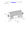
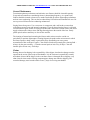
ORDER DIRECTLY TODAY AT: www.BulbAmerica.com or CALL TOLL FREE 888-505-2111
iLED-30
USER MANUAL
Snapshot
OK on Dimmer
Outdoor OK
Sound Activated Option
DMX-512
Master/Slave
115V/230V
Switch
Please read these instructions carefully before use.
ORDER DIRECTLY TODAY AT: www.BulbAmerica.com or CALL TOLL FREE 888-505-2111
TABLE OF CONTENTS
1. BEFORE YOU BEGIN......................................................................................................................................................2
WHAT IS INCLUDED...................................................................................................................................................................2
UNPACKING INSTRUCTIONS....................................................................................................................................................2
AC POWER ...........................................................................................................................................................................2
SAFETY INSTRUCTIONS.........................................................................................................................................................3
2. INTRODUCTION .........................................................................................................................................................4
FEATURES .............................................................................................................................................................................4
DMX CHANNEL SUMMARY.....................................................................................................................................................4
PRODUCT OVERVIEW ...........................................................................................................................................................5
3. SETUP.............................................................................................................................................................................6
FIXTURE LINKING...................................................................................................................................................................6
Data Cabling ........................................................................................................................................................................6
DMX Data Cable..................................................................................................................................................................6
Cable Connectors.................................................................................................................................................................7
3-Pin to 5-Pin Conversion Chart ............................................................................................................................................................7
SETTING UP A DMX SERIAL DATA LINK ..............................................................................................................................7
MASTER/SLAVE FIXTURE LINKING ......................................................................................................................................8
MOUNTING ...........................................................................................................................................................................9
Orientation ......................................................................................................................................................................... 9
Rigging..................................................................................................................................................................................9
4. OPERATING INSTRUCTIONS.........................................................................................................................................................9
MENU MAP....................................................................................................................................................................... ...10
MENU FUNCTIONS .............................................................................................................................................................. 11
OPERATION.........................................................................................................................................................................12
Standalone & Master/Slave Operation:................................................................................................................................ …...12
DMX-512 Mode.................................................................................................................................................................. 14
5. APPENDIX......................................................................................................................................................................................... 14
DMX PRIMER................................................................................................................................................................... 14
PHOTOMETRICS .............................................................................................................................................................. .15
GENERAL MAINTENANCE ................................................................................................................................................ 16
CLAIMS ........................................................................................................................................................................... .16
TECHNICAL SPECIFICATIONS........................................................................................................................................... 17
Size………………………................................................................................................................................................... 18
1
ORDER DIRECTLY TODAY AT: www.BulbAmerica.com or CALL TOLL FREE 888-505-2111
1. BEFORE YOU BEGIN
What is included
•
•
1 x iLED-30
Users Manual
Unpacking Instructions
Immediately upon receiving a fixture, carefully unpack the carton, check the contents to ensure
that all parts are present, and have been received in good condition. Notify the shipper
immediately and retain packing material for inspection if any parts appear damaged from
shipping or the carton itself shows signs of mishandling. Save the carton and all packing
materials. In the event that a fixture must be returned to the factory, it is important that the fixture
be returned in the original factory box and packing.
AC Power
This fixture has an auto-switching power supply that can accommodate a wide range of input
voltages. The only thing necessary to do before powering on the unit is to make sure the line
voltage you are applying is within the range of accepted voltages. This fixture will
accommodate between 100V and 240V AC. All fixtures must be powered directly off a
switched circuit and cannot be run off a rheostat (variable resistor) or dimmer circuit, even if
the rheostat or dimmer channel is used solely for a 0% to 100% switch.
2
ORDER DIRECTLY TODAY AT: www.BulbAmerica.com or CALL TOLL FREE 888-505-2111
Safety Instructions
Please read these instructions carefully, this includes
important information about the installation, usage and
maintenance of this product.
• Please keep this User Guide for future consultation. If you sell the unit to another user, be sure
that they also receive this instruction booklet.
• Always make sure that you are connecting to the proper voltage, and that the line voltage you
are connecting to is not higher than that stated on the decal or rear panel of the fixture.
• Make sure there are no flammable materials close to the unit while operating.
• Always disconnect from power source before servicing or replacing fuse and be sure to replace
with same fuse source.
• Secure fixture to fastening device using a safety chain.
• Maximum ambient temperature (Ta) is 95°F (35°C). Do not operate fixture at temperatures
higher than this.
• In the event of a serious operating problem, stop using the unit immediately. Never try to repair
the unit by yourself. Repairs carried out by unskilled people can lead to damage or malfunction.
Please contact the nearest authorized technical assistance center. Always use the same type
spare parts.
• Don’t connect the device to a dimmer pack.
• Make sure the power cord is never crimped or damaged.
• Never disconnect the power cord by pulling or tugging on the cord.
• Avoid direct eye exposure to the light source while it is on.
• Do not daisy chain power to more than 20 units at 120V, or 40 units at 230V.
Caution! There are no user serviceable parts inside the unit. Do not open the housing or
attempt any repairs yourself. In the unlikely event your unit may require service,
please contact your vendor
3
ORDER DIRECTLY TODAY AT: www.BulbAmerica.com or CALL TOLL FREE 888-505-2111
2. INTRODUCTION
Features
• 4-channel DMX-512 LED LIGHT (with ID addressing)
• Blackout/static/dimmer/strobe/pulse
• RGB color mixing with or without DMX controller
Additional Features
• Durable and weather resistant IP65 rated
• LED display with lock-out feature
• Low power consumption
DMX Channel Summary
Channel
1
2
3
4
Function
Red 0% -> 100%
Green 0% -> 100%
Blue 0% -> 100%
Dimmer 0% -> 100%
Strobe Slow -> Fast
Color Scroll Fast -> Slow
4
Value/Level
000-255
000-255
000-255
000-127
128-199
200-255
ORDER DIRECTLY TODAY AT: www.BulbAmerica.com or CALL TOLL FREE 888-505-2111
Product Overview
5
ORDER DIRECTLY TODAY AT: www.BulbAmerica.com or CALL TOLL FREE 888-505-2111
3. SETUP
Fixture Linking
You will need a serial data link to run light shows of one or more fixtures using a DMX-512
controller or to run synchronized shows on two or more fixtures set to a master/slave operating
mode. The combined number of channels required by all the fixtures on a serial data link
determines the number of fixtures the data link can support.
Important: Fixtures on a serial data link must be daisy chained in one single line. To comply with
the EIA-485 standard no more than 32 devices should be connected on one data link.
Connecting more than 32 fixtures on one serial data link without the use of a DMX
optically-isolated splitter may result in deterioration of the digital DMX signal.
Maximum recommended serial data link distance: 500 meters (1640 ft.)
Maximum recommended number of fixtures on a serial data link: 32 fixtures
Data Cabling
To link fixtures together you must obtain data cables. You can purchase certified DMX cables
directly from a dealer/distributor or construct your own cable. If you choose to create your own
cable please use data-grade cables that can carry a high quality signal and are less prone to
electromagnetic interference.
DMX DATA CABLE
Use a Belden© 9841 or equivalent cable which meets the specifications for EIA RS-485
applications. Standard microphone cables cannot transmit DMX data reliably over long distances.
The cable will have the following characteristics:
2-conductor twisted pair plus a shield
Maximum capacitance between conductors – 30 pF/ft.
Maximum capacitance between conductor and shield – 55 pF/ft.
Maximum resistance of 20 ohms / 1000 ft.
Nominal impedance 100 – 140 ohms
6
ORDER DIRECTLY TODAY AT: www.BulbAmerica.com or CALL TOLL FREE 888-505-2111
CABLE CONNECTORS
Cabling must have a male XLR connector on one end and a female XLR connector on the other
end.
CAUTION: Do not allow contact between the common and the fixture’s chassis ground.
Grounding the common can cause a ground loop, and your fixture may perform erratically Test
cables with an ohm meter to verify correct polarity and to make sure the pins are not grounded or
shorted to the shield or each other.
3-PIN TO 5-PIN CONVERSION CHART
Note! If you use a controller with a 5 pin DMX output connector, you will need to use a 5 pin to 3
pin adapter.
The chart below details a proper cable conversion:
3 PIN TO 5 PIN CONVERSION CHART
Conductor
Ground/Shield
Data ( - ) signal
Data ( + ) signal
Do not use
Do not use
3 Pin Female (output)
Pin 1
Pin 2
Pin 3
5 Pin Male (Input)
Pin 1
Pin 2
Pin 3
Do not use
Do not use
Setting up a DMX Serial Data Link
1. Connect the (male) 3 pin connector side of the DMX cable to the output (female) 3 pin
connector of the controller.
2. Connect the end of the cable coming from the controller which will have a (female) 3
pin connector to the input connector of the next fixture consisting of a (male) 3 pin connector.
Universal DMX
Controller
Continue
the link
7
ORDER DIRECTLY TODAY AT: www.BulbAmerica.com or CALL TOLL FREE 888-505-2111
Master/Slave Fixture Linking
1. Connect the (male) 3 pin connector side of the DMX cable to the output (female) 3 pin
connector of the first fixture.
2. Connect the end of the cable coming from the first fixture which will have a (female) 3 pin
connector to the input connector of the next fixture consisting of a (male) 3 pin connector. Then,
proceed to connect from the output as stated above to the input of the following fixture and so on.
3. If the client requests the AC power cable with the plug, we may configure it.
TO DMX
CONTROLLE
R
1---GND
2---DATA3---DATA+
TO AC POWER SUPPLY
GND---(GREEN / YELLOW CABLE)
NEUTRAL---(WHTE / BLUE CABLE)
LIVE---(BLACK / BROWN CABLE)
TO THE NEXT
UNIT DMX IN
Often, the setup for Master-Slave and Standalone operation
requires that the first fixture in the chain be initialized for this
purpose via either settings in the control panel or DIPswitches.
Secondarily, the fixtures that follow may also require a slave
setting. Please consult the “Operating Instructions” section in
this manual for complete instructions for this type of setup and
configuration.
8
Mounting
ORIENTATION
This fixture may be mounted in any position provided there is adequate room for ventilation.
RIGGING
Hanging Clamp
It is important never to obstruct the fan or vents pathway. Mount
The fixture using, four 8mm screws. Adjust the angle of the
fixture by loosening both knobs and tilting the fixture. After finding the
desired position, retighten both knobs
• When selecting installation location, take into consideration lamp
replacement access and routine maintenance.
• Safety cables must always be used.
• Never mount in places where the fixture will be exposed to rain, high.
humidity, extreme temperature changes or restricted ventilation.
4. OPERATING INSTRUCTIONS
Note!
Clamp is sold separately.
Navigating the Control Panel
Access control panel functions using the four panel buttons located directly underneath the
LED Display.
Button
Function
<MENU> To select the programming functions.
<ENTER> To confirm the selected functions.
<VAL+>
To setting DMX value up.
<VAL->
To setting DMX value down.
9
ORDER DIRECTLY TODAY AT: www.BulbAmerica.com or CALL TOLL FREE 888-505-2111
Menu Map
ADDR
1-511
Shnd
A0-A9
SVAL
1-8
blnd
n bo
Y bo
LEd
On
OFF
Fadj
Fadj
test
test
Fhrs
Fhrs
1-9999
rSet
rSet
iLEd
10
ORDER DIRECTLY TODAY AT: www.BulbAmerica.com or CALL TOLL FREE 888-505-2111
Menu Function
Menu
Display
ADDR
Function
Values
Set the DMX address of the unit.
Shnd
Sound controlled built in
programmes
Speed/Fade Settings/ single color
selection for Shnd programs
Control on/off function of the light
Set between 1 and 511. Each unit is 4
DMX channels
A0 to A9
SVAL
blnd
LED
Setting for the LED display to be on
or off when not being used
Fadj
In this mode, pressing the [ENTER]
button will change the color and
hold. Press [Enter] again the next
color will output
In this mode, a range of colors will
cycle through when [ENTER] is
pressed.
Display the number of operational
hours of the unit by pressing
[ENTER]
Reset the unit by pressing [ENTER]
test
Fhrs
rSet
11
1 to 8
y bo
Unit is blacked out (off)
n bo
Unit is on and pre-programs can
be used
LED display is always on
The LED display will turn off
after 10 seconds. Press the
[MENU] button to illuminate
the LED display
on
OFF
ORDER DIRECTLY TODAY AT: www.BulbAmerica.com or CALL TOLL FREE 888-505-2111
Operation
Standalone & Master/Slave Operation
When multiple units are linked together via 3pin XLR cables (sold separately), the first unit in the
chain will act as the Master and will send data (DMX-512) to the other units (Slaves).
By linking the units in master/slave connection, the first unit will control the other units to give an
automatic synchronized light show.
The uint is normally without sound activated function. If the client request the unit with sound
activated function and it is only used in the indoor case ,we may configure the function.
iLED-30 has built-in programs that are accessed via [Shnd] Menu.
Shnd Pre-Programmes
A0
The LEDs fade continuously between
the preset 12 colors in loop mode
A1
The preset 12 colors step continuously
in loop mode
A3
Glittering, the color changes constantly
in loop mode
12
SVAL Settings
1-8
Select one fade time from 1 to 8.
1
1sec
2
2sec
3
3sec
4
4sec
5
5sec
6
6sec
7
8sec
8
10sec
1-8
Select one color hold time from 1 to 8
1
1sec
2
2sec
3
3sec
4
4sec
5
5sec
6
6sec
7
8sec
8
10sec
1-8
Select one color hold time from 1 to 8
1
1sec
2
2sec
3
3sec
4
4sec
5
5sec
6
6sec
7
8sec
8
10sec
ORDER DIRECTLY TODAY AT: www.BulbAmerica.com or CALL TOLL FREE 888-505-2111
A4
A5
A6
A7
A8
A9
iLED-30 reacts to sound only,
changing color with the music. When
the music/sound stops the LED
PARCan stays on the last color
iLED-30 reacts to sound only,
changing color with the music. When
the music/sound stops the LED
PARCan turns off after 10 seconds
iLED-30 reacts to sound only,
changing color with the music. When
the music/sound stops the LED
PARCan will be change color once
after 3 seconds
iLED-30 reacts to sound only,
Strobing quickly and changing color
with the music. When the
music/sound stops LED light will
turn off after 1.2 seconds
iLED-30 reacts to sound only,
Glittering and changing color with
the music. When the music/sound
stops LED light will turn off after 2.4
seconds
iLED-30 single color selection
1-8
Option
1-8
Option
1-8
Option
1-8
Option
1-8
Option
1-8
1 Red
2 Orange
3 Yellow
4 Green
5 Cyan
6 Blue
7 Magenta
8 White
13
ORDER DIRECTLY TODAY AT: www.BulbAmerica.com or CALL TOLL FREE 888-505-2111
DMX-512 Mode
If you use a universal DMX controller to control the units, you have to set DMX address from 1
to 511 channel so that the units can receive DMX signal.
Press the MENU button up to when the
is showing on the display. Pressing ENTER
button and the display will light on. Use “VAL- “ and “VAL+ “ button to change the DMX-512
address. Once the address has been selected, press ENTER button to storing the setting. To go
back to the functions without any change press the MENU button again. Please refer to the
following diagram to address your DMX-512 channel for the units.
4 DMX-512 channels:
DMX Channels
Each iLED-30 has 4 control channels, DMX channel value refer to the 5th page.
5. APPENDIX
DMX Primer
There are 512 channels in a DMX-512 connection. Channels may be assigned in any manner. A
fixture capable of receiving DMX-512 will require one or a number of sequential channels. The
user must assign a starting address on the fixture that indicates the first channel reserved in the
controller. There are many different types of DMX controllable fixtures and they all may vary in
the total number of channels required. Choosing a start address should be planned in advance.
Channels should never overlap. If they do, this will result in erratic operation of the fixtures
whose starting address is
set incorrectly. You can however, control multiple fixtures of the same type using the same
starting address as long as the intended result is that of unison movement or operation. In other
words, the fixtures will be slaved together and all respond exactly the same. DMX fixtures are
designed to receive data through a serial Daisy Chain. A Daisy Chain connection is where the
DATA OUT of one fixture connects to the DATA IN of the next fixture. The order in which the
fixtures are connected is not important and has no effect on how a controller communicates to
each fixture. Use an order that provides for the easiest and most direct cabling. Connect fixtures
using shielded two conductor twisted pair cable with three pin XLR male to female connectors.
The shield connection is pin 1, while pin 2 is Data Negative (S-) and pin 3 is Data positive (S+).
14
ORDER DIRECTLY TODAY AT: www.BulbAmerica.com or CALL TOLL FREE 888-505-2111
15
ORDER DIRECTLY TODAY AT: www.BulbAmerica.com or CALL TOLL FREE 888-505-2111
General Maintenance
To maintain optimum performance and minimize wear fixtures should be cleaned frequently.
Usage and environment are contributing factors in determining frequency. As a general rule,
fixtures should be cleaned at least twice a month. Dust build up reduces light output performance
and can cause overheating. This can lead to reduced lamp life and increased mechanical wear. Be
sure to power off fixture before conducting maintenance.
Unplug fixture from power. Use a vacuum or air compressor and a soft brush to remove dust
collected on external vents and internal components. Clean all glass when the fixture is cold with
a mild solution of glass cleaner or Isopropyl Alcohol and a soft lint free cotton cloth or lens tissue.
Apply solution to the cloth or tissue and drag dirt and grime to the outside of the lens. Gently
polish optical surfaces until they are free of haze and lint.
The cleaning of internal and external optical lenses and/or mirrors must be carried out
periodically to optimize light output. Cleaning frequency depends on the environment in which
the fixture operates: damp, smoky or particularly dirty surrounding can cause greater
accumulation of dirt on the unit’s optics. Clean with soft cloth using normal glass cleaning fluid. Always dry the parts carefully. – Clean the external optics at least every 20 days. Clean the
internal optics at least every 30/60 days.
Claims
Damage incurred in shipping is the responsibility of the shipper; therefore the damage must be
reported to the carrier upon receipt of merchandise. It is the customer's responsibility to notify
and submit claims with the shipper in the event that a fixture is damaged due to shipping. Any
other claim for items such as missing component/part, damage not related to shipping, and
concealed damage, must be made within seven (7) days of receiving merchandise.
16
ORDER DIRECTLY TODAY AT: www.BulbAmerica.com or CALL TOLL FREE 888-505-2111
Technical Specifications
WEIGHT & DIMENSIONS
Length................................................................................................................... 16.5 in (418 mm)
Width ...................................................................................................................... 3.6 in (92 mm)
Height ..................................................................................................................... 7.1 in (181 mm)
Weight .....................................................................................................................2.75 lbs (2.5 kg)
POWER
Operating Voltage ........................................................................................100V ~ 240V 50/60 Hz
Power Consumption .............................................................................................47W (0.47A) Max
Inrush Current .............................................................................................................1.0A at 120V
Power Factor .................................................................................................................0.8 at 120V
LIGHT SOURCE
LED.........................................................................................30 x 1W (10 Red, 10 Green, 10 Blue)
PHOTO OPTIC
Illuminance at 1m ...................................................................................................685 fc (7364 lux)
Beam Angle............................................................................................................................. 19.3°
Field Angle.................................................................................................................................. 40°
THERMAL
Maximum ambient temperature...................................................................................95°F (35°C)
CONTROL & PROGRAMMING
Data input ........................................................................................ locking 3-pin XLR male socket
Data output ................................................................................... locking 3-pin XLR female socket
Data pin configuration .......................................................................pin 1 shield, pin 2 (-), pin 3 (+)
Protocols................................................................................................................ DMX-512 USITT
DMX Channels ...............................................................................................................................4
ORDERING INFORMATION
iLED-30 Black................................................................................................................... iLED-30B
iLED-30 Silver................................................................................................................... iLED-30S
iLED-30 White.....................................................................................................................iLED-30W
WARRANTY INFORMATION
Warranty...................................................................................................... 1-year limited warranty
17
ORDER DIRECTLY TODAY AT: www.BulbAmerica.com or CALL TOLL FREE 888-505-2111
SIZE
18