1
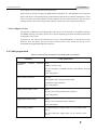
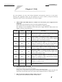
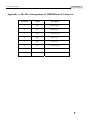
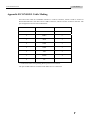
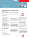
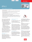
www.raisecom.com
RC959-4FE16E1-BL User Manual
Legal Notices
Raisecom Technology Co., Ltd makes no warranty of any kind with regard to this manual,
including, but not limited to, the implied warranties of merchantability and fitness for a particular
purpose. Raisecom Technology Co., Ltd shall not be held liable for errors contained herein or direct,
indirect, special, incidental or consequential damages in connection with the furnishing, performance,
or use of this material.
Warranty.
A copy of the specific warranty terms applicable to your Raisecom product and replacement parts
can be obtained from Service Office.
Restricted Rights Legend.
All rights are reserved. No part of this document may be photocopied, reproduced, or translated to
another language without the prior written consent of Raisecom Technology Co., Ltd. The
information contained in this document is subject to change without notice.
Copyright Notices.
Copyright ©2007 Raisecom. All rights reserved.
No part of this publication may be excerpted, reproduced, translated or utilized in any form or by any
means, electronic or mechanical, including photocopying and microfilm, without permission in
Writing from Raisecom Technology Co., Ltd.
Trademark Notices
is the trademark of Raisecom Technology Co., Ltd.
Java™ is a U.S. trademark of Sun Microsystems, Inc.
Microsoft® is a U.S. registered trademark of Microsoft Corporation.
Windows NT® is a U.S. registered trademark of Microsoft Corporation.
Windows® 2000 is a U.S. registered trademark of Microsoft Corporation.
Windows® XP is a U.S. registered trademark of Microsoft Corporation.
Windows® and MS Windows® are U.S. registered trademarks of
Microsoft Corporation.
Contact Information
Technical Assistance Center
The Raisecom TAC is available to all customers who need technical assistance with a Raisecom
product, technology, or, solution. You can communicate with us through the following methods:
Address:
2nd Floor, South Building of Rainbow Plaza, No.11 Shangdi Information Road,
Haidian District, Beijing 100085
Tel:
+86-10-82883305
Fax:
+86-10-82883056
World Wide Web
You can access the most current Raisecom product information on the World Wide Web at the
following URL:
http://www.raisecom.com
Feedback
Comments and questions about how the RC959-4FE16E1-BL device works are welcomed. Please
review the FAQ in the related manual, and if your question is not covered, send email by using the
following web page:
http://www.raisecom.com/en/xcontactus/contactus.htm.
If you have comments on the RC959-4FE16E1-BL specification, instead of the web page above,
please send comments to:
[email protected]
We hope to hear from you!
CONTENTS
Release Notes------------------------------------------------------------------------------------------------- 5
Chapter 1
Overview ------------------------------------------------------------------------------------ 1
1.1
1.2
1.3
Main features ---------------------------------------------------------------------------------------------------------------1
Device naming rules ------------------------------------------------------------------------------------------------------2
Device exterior and dimension-----------------------------------------------------------------------------------------2
Chapter 2
Technical Specifications ---------------------------------------------------------------- 3
2.1 Basic configuration------------------------------------------------------------------------------------------------------------3
2.2 Ethernet interface properties -----------------------------------------------------------------------------------------------3
2.2.1 Electrical interface ------------------------------------------------------------------------------------------------------------------------- 3
2.2.2 Optical interface ---------------------------------------------------------------------------------------------------------------------------- 3
2.3 E1 interface properties -------------------------------------------------------------------------------------------------------3
2.4 Power supply -------------------------------------------------------------------------------------------------------------------4
2.5 Working environment---------------------------------------------------------------------------------------------------------4
Chapter 3
Device Structure and Indicator Definition----------------------------------------- 5
3.1 Panel direction description --------------------------------------------------------------------------------------------------5
3.2 Alarm and performance data -----------------------------------------------------------------------------------------------8
Chapter 4
Installation and Testing-----------------------------------------------------------------11
4.1 Cautions ----------------------------------------------------------------------------------------------------------------------- 11
4.2 Installation process --------------------------------------------------------------------------------------------------------- 11
4.2.1 Connect the SNMP network management interface -----------------------------------------------------------------------------11
4.2.2 Connect the CONSOLE interface -----------------------------------------------------------------------------------------------------11
4.2.3 Connect the Ethernet interface ------------------------------------------------------------------------------------------------------- 12
4.2.4 Connect E1 cable ------------------------------------------------------------------------------------------------------------------------ 12
4.2.5 Electrify ------------------------------------------------------------------------------------------------------------------------------------- 12
4.2.6 Configure services ----------------------------------------------------------------------------------------------------------------------- 13
4.3 Cable preparation ----------------------------------------------------------------------------------------------------------- 13
Chapter 5
FAQ--------------------------------------------------------------------------------------------14
Appendix A The Pin Arrangement of 120Ω Balanced Connector ---------------------------16
Appendix B CONSOLE Cable Making----------------------------------------------------------------17
Appendix C Specialized Terms and Acronyms ---------------------------------------------------18
Release Notes
Date of Release
Manual Version
20080603
200803
Revisions
V1.0 (first draft)
General Safety Instructions
The following instructions serve as a general guide for the safe installation and operation of telecommunications
products. Additional instructions, if applicable, are included inside the manual.
Safety Symbols
This symbol may appear on the equipment or in the text. It indicates potential
safety hazards regarding product operation or maintenance to operator or service
personnel.
Danger of electric shock! Avoid any contact with the marked surface while the
product is energized or connected to outdoor telecommunication lines.
Protective earth: the marked lug or terminal should be connected to the building
protective earth bus.
Some products may be equipped with a laser diode. In such cases, a label with
the laser class and other warnings as applicable will be attached near the optical
transmitter. The laser warning symbol may be also attached.
Please observe the following precautions:
• Before turning on the chassis with optic module, make sure that the fiber optic
cable is intact and is connected to the transmitter.
• Do not attempt to adjust the laser drive current.
• Do not use broken or unterminated fiber-optic cables/connectors or look straight at the
laser beam.
• The use of optical devices with the equipment will increase eye hazard.
• Use of controls, adjustments or performing procedures other than those specified herein, may
result in hazardous radiation exposure.
ATTENTION: The laser beam may be invisible!
Always observe standard safety precautions during installation, operation and maintenance of this
product. Only qualified and authorized service personnel should carry out adjustment, maintenance
or repairs to this product. No installation, adjustment, maintenance or repairs should be performed by
either the operator or the user.
All extension slots are not hot-swappable
Before operating modules in the electricity conditions, please be noticed that optical modules shall
be connected with optical fiber wires or shield with optical module cover for fear that laser light
harms to operator’s eyes.
Handling Energized Products
General Safety Practices
Do not touch or tamper with the power supply when the power cord is connected. Line voltages may
be present inside certain products even when the power switch (if installed) is in the OFF position or
a fuse is blown. For DC-powered products, although the voltages levels are usually not hazardous,
energy hazards may still exist.
Before working on equipment connected to power lines or telecommunication lines, remove jewelry
or any other metallic object that may come into contact with energized parts.
Unless otherwise specified, all products are intended to be grounded during normal use. Grounding
is provided by connecting the mains plug to a wall socket with a protective earth terminal. If an earth
lug is provided on the product, it should be connected to the protective earth at all times, by a wire
with a diameter of 18 AWG or wider. Rack-mounted equipment should be mounted only in earthed
racks and cabinets.
Always make the ground connection first and disconnect it last. Do not connect telecommunication
cables to ungrounded equipment. Make sure that all other cables are disconnected before
disconnecting the ground.
Connection of AC Mains
Make sure that the electrical installation complies with local codes.
Always connect the AC plug to a wall socket with a protective ground.
Always connect the power cord first to the equipment and then to the wall socket. If a power switch
is provided in the equipment, set it to the OFF position. If the power cord cannot be readily
disconnected in case of emergency, make sure that a readily accessible circuit breaker or emergency
switch is installed in the building installation.
Connection of DC Mains
Unless otherwise specified in the manual, the DC input to the equipment is floating in reference to
the ground. Any single pole can be externally grounded.
Due to the high current capability of DC mains systems, care should be taken when connecting the
DC supply to avoid short-circuits and fire hazards.
DC units should be installed in a restricted access area, i.e. an area where access is authorized only to
qualified service and maintenance personnel.
Make sure that the DC supply is electrically isolated from any AC source and that the installation
complies with the local codes.
Before connecting the DC supply wires, ensure that power is removed from the DC circuit. Locate
the circuit breaker of the panel board that services the equipment and switch it to the OFF position.
When connecting the DC supply wires, first connect the ground wire to the corresponding terminal,
then the positive pole and last the negative pole. Switch the circuit breaker back to the ON position.
A readily accessible disconnect device that is suitably rated and approved should be incorporated in
the building installation.
Preventing Electrostatic Discharge Damage
Modules which can be plugged into chassis are sensitive to damage from static electricity.
Conversely, static voltages as high as 35,000V can be generated just by handling plastic or foam
packing material, or by sliding assemblies across plastic and carpets. Not exercising the proper
electrostatic discharge (ESD) precautions can result in intermittent or complete component failures.
To minimize the potential for ESD damage, observe the following guidelines:
• Always use an ESD-preventive antistatic wrist strap or ankle strap and ensure that it makes good
skin contact.
• When removing or installing a component, make sure the equipment end of your antistatic strap
leash is connected to the ESD connection sockets on the front of the chassis or to a bare metal
surface on the chassis. Avoid contact between the component and your clothing. The wrist strap only
protects the component from ESD voltages on the body; ESD voltages on your clothing can still
cause component damage.
• Always place a card component-side-up on an antistatic surface, in an antistatic card rack, or in a
static shielding bag. If you are returning the item to the factory, immediately place it in a static
shielding bag.
• Handle Modules by the metal card carrier edges only; Avoid touching the board or any connector
pins.
www.raisecom.com
User Manual
Chapter 1 Overview
RC959-4FE16E1 (-BL) is a central site interface converter with VLAN function and inverse
multiplexing function. It provides 4 FE interfaces (3 electrical interfaces and 1 optical interface) and
16 E1 interfaces and is mostly used to access or transmit Ethernet services with bandwidth larger
than 2Mbps and smaller than 32Mbps.
Classifying by the type of E1 interface, Raisecom provides RC959-4FE16E1(-BL) with 75Ω
unbalanced E1 interfaces and RC959-4FE16E1(-BL) with 120Ω balanced E1 interfaces.
1.1 Main features
¾
¾
¾
¾
¾
¾
¾
¾
¾
¾
16 E1 interfaces
z Balanced or unbalanced interface can be chosen;
z Framed mode of transparent mode can be chosen; only 1 line of E1 in VCG (Virtual
Cascade Group) under transparent mode;
z Users configurable for CRC auto-negotiation, in support of PCM31 format of
FAS+CRC4 and PCM30 format of FAS+CAS+CRC4 under framed mode;
z Supports E1 loopback test;
z Supports E1 error bit statistics function;
z Supports LCAS (Link Capacity Adjustment Strategy);
z Supports E1 link Auto-MDI/MDIX.
VCAT function
z Supports one VCG only and at most 16 E1 virtual cascade members can be allocated to
the VCG;
z Supports VCG LCAS;
z Supports alarm and statistics information in VCG;
z Supports relatively time delay of E1 member for +/-250ms.
Ethernet encapsulation format supports GFP, LAPS, PPP and HDLC
Ethernet interface
z 4 FE interfaces (3 electrical interfaces and 1 optical interface), SFP connector for optical
interface;
z Supports maximal frame size of 12000 bytes;
z The electrical interfaces support 10M/100M, full-duplex/half-duplex, auto-negotiation,
802.3X flow control, MDI/MDIX;
z The optical interface supports 100BASE-FX, flow control, SFP ALS (automatic
laser-shutdown);
z Ethernet interfaces performance statistics.
VLAN forward function of Ethernet service
z The device can work in VLAN-UNAWARE mode, VLAN-AWARE mode and
Double-tag (Q-in-Q) mode;
z VLAN-AWARE mode and Double-tag (Q-in-Q) mode support adding and stripping tag.
z Supports all 4096 VLAN ID, meanwhile 16 forward rules can be configured, one
forward rule corresponding one VLAN ID.
CONSOLE interface
SNMP network management interface, in support of local and remote software online
upgrade, easy to maintain
Full-scale network management function can manage over both local device and remote
RC959 interface converter
Standard 19 inch, 1U chassis
Power consumption < 10W and working stably
1
www.raisecom.com
User Manual
¾
¾
Redundant power supply design, AC/DC selectable
Working temperature: -5~50℃
1.2 Device naming rules
The device is composed of main circuit board and power supply board.
Devices naming rule: RC959
–A
–B
–C
BL
AC
blank
DC
4FE16E1
Explanation:
RC959: the device is EOPDH inverse multiplexer in support of GFP encapsulation.
A: FE type and the number of E1 interface.
4FE16E1: 4 FE interfaces, 3 electrical interfaces and 1 optical interface
16 E1 interfaces
B: type of E1 interface, could be BL or blank.
BL indicates that is a 120Ω RJ45 balanced interface.
Blank indicates that is a 75Ω BNC unbalanced interface.
C: type of power supply, could be AC or DC.
AC indicates that the device adopts 220V AC power supply
DC indicates that the device adopts -48V DC power supply
Device mode that adopts 24V DC power supply can be made to order.
For detailed available product list, please refer to product ordering information.
1.3 Device exterior and dimension
RC959-4FE16E1-BL adopts international standard 19 inch 1U chassis.
Dimension: 430 mm (Width) x 44.45 mm (Height) x 266 mm (Depth)
2
www.raisecom.com
User Manual
Chapter 2 Technical Specifications
2.1 Basic configuration
¾
¾
Main circuit board: 4 FE interfaces (3 electrical interfaces and 1 optical interface) and 16 E1
interfaces
Power supply: redundant power supply, 220V/AC or -48V/DC
2.2 Ethernet interface properties
2.2.1 Electrical interface
¾
¾
¾
¾
¾
¾
Interface number: 3
Rate: 10/100M auto-negotiation
Connector: RJ-45
In support of IEEE802.3 recommendation
In support of IEEE802.3x flow control
Host pin arrangement, in support of AUTO-MDIX
2.2.2 Optical interface
¾
¾
¾
Interface number: 1
Rate: 100M
Connector: SFP module, LC connector
2.3 E1 interface properties
¾
¾
¾
¾
¾
¾
¾
¾
¾
¾
¾
¾
¾
¾
¾
Number of E1 interfaces: 16
E1 Interface connector: 75Ω unbalanced BNC connector or 120Ω balanced RJ-45 connector
Bit Rate: 2048Kbps±50ppm
Code type: HDB3
Input impedance: 75Ω unbalanced or 120Ω balanced
Electrical characteristics: compliant to ITU-T G 703 recommendation
Frame structure: compliant to ITU-T G.704 recommendation
Jitter: compliant to ITU-T G.823 recommendation
Ethernet data adopts GFP, LAPS, PPP, HDLC encapsulation format
Framed or transparent mode is optional. Only 1 E1 line in VCG under transparent mode
In framed mode:
PCM31 format of FAS+CRC4 is supported, PCM30 format of FAS+CAS+CRC4 is
supported, CRC auto-negotiation and configurable
Maximal relative time delay of E1: +/-250ms
One LOS indicator corresponding to every E1 line, which provides alarms for command lines
and network management
Local alarms include LOS (Loss Of Signal), AIS (Alarm Indication Signal), LOF (Loss Of
Frame) and CRC (Cyclic Redundancy Check)
Remote alarms include LOS, AIS, LOF and CRC
In support of E1 link local and remote loopback test
In support of E1 link error bit ratio statistics function
In-band network management via E1 line can manage remote RC959 interface converter
3
www.raisecom.com
User Manual
2.4 Power supply
¾
¾
¾
Redundant power supply
Voltage of power supply: DC -48V with allowance range -36V~-72V
AC 220V, allowance range 180V~260V
Power consumption: <10W
2.5 Working environment
¾
¾
Temperature: -5℃~50℃
Relative humidity: ≤90% (35℃)
4
www.raisecom.com
User Manual
Chapter 3 Device Structure and Indicator Definition
All RC959 series devices have the same size, but their panel appearance varies with different E1
balanced/unbalanced interface and AC/DC power supply.
3.1 Panel direction description
The figure 3-1 and figure 3-2 shows front panel of RC959-4FE16E1-BL with AC/DC,
balanced/unbalanced interface.
Front panel figures with AC/DC power supply:
Rear panel figure with balanced interface:
Explanation of indicators on RC959-4FE16E1 as table 3-1 show:
Table 3-1 RC959-4FE16E1 front panel indicators explanation
Serial number
Title
Color
Description
LOGO and
device model
-
For device with balanced E1 interfaces and device with
unbalanced E1 interfaces, the device model typed on the
device panel are the same: RC959-4FE16E1.
1
SYS
Green
Upper: Flickering (ON 0.5s and OFF 0.5s alternately): the
device is operating normally.
PWR
Green
DOWN: the power supply of the device is working in
order.
PWR1
Green
PWR1 is the indicator for power supply 1. ON indicates
2
3
5
www.raisecom.com
User Manual
that power supply is working normally.
PWR2 is the indicator for power supply 2. ON indicates
that power supply is working normally.
The meanings of the combination of PWR, PWR1 and
PWR2:
PWR2
PWR
PWR1
PWR2
ON
ON
ON
The two power supplies are both
working in order and the device
power supply is working
normally.
ON
ON
OFF
Power supply 1 is working in
order; voltage of power supply
2 is too low, and power of the
device is supplied by power
supply 1 and working normally.
ON
OFF
ON
The voltage of power supply 1
is too low, the power supply 2 is
working in order, and power of
the device is supplied by power
supply 2 and working normally.
OFF
ON
ON
The two power supplies are both
working normally, but the
power supply of the device is
not working in order.
OFF
ON
OFF
The power supply 1 is working
normally, voltage of the power
supply 2 is too low, and the
power supply of the device is
not working in order.
OFF
OFF
ON
The voltage of power supply 1 is
too low, the power supply 2 is
working in order, and the
device’s power supply is not
working normally.
OFF
OFF
OFF
The device is powered on or
neither of the two power
supplies is working in order.
ON
OFF
OFF
Some abnormity occurs.
Green
Meanings
LOS: Loss of signal. One LOS indicator for one E1 line.
4
E1 LOS
Red
ON: loss of local E1 receiving signal.
OFF: receiving signal has been detected.
5
CONSOLE
interface
6
SNMP
interface and
indicator
-
Local CONSOLE, connected to the serial port of PC.
SNMP interface with 2 indicators: LNK/ACT and 100M.
-
LNK/ACT: ON indicates that the link is connected.
Flicking indicates that there is data being transmitted or
received.
6
www.raisecom.com
User Manual
100M: Indicates working rate is 100M.
OFF: Indicates working rate is 10M.
Three Ethernet electrical interfaces, 2 indicators for each.
LNK/ACT: ON indicates that the link has been set up.
Flickering: indicates receiving or sending date.
7
FE1~FE3
interface
Green
OFF indicates that the link has not been set up.
100M: ON indicates that the interface is working at the
rate of 100M.
OFF indicates that the interface is working at the rate of
10M.
Ethernet optical interface, SFP interface, 2 indicators.
LNK/ACT: ON indicates that the link has been set up.
8
FE4 interface -Green
Flickering indicates that there is data transmitting or
receiving.
OFF indicates that the link has not been set up.
SD: ON indicates that optical signal has been detected.
OFF indicates that no optical signal has been detected.
2 power supply sockets.
3-pole socket for AC power supply chassis.
Socket with 3 terminals for DC power supply chassis:
9
Power supply
socket
-
-48V: left terminal, connect with the negative polarity of
the power supply.
PGND: middle terminal, the inside part of the terminal
connect to the device shell.
BGND: right terminal, power supply earth.
10
Power supply
switch
One switch for one power supply.
-
ON: upper, the power is on.
OFF: down, the power is off.
11
12
Grounding
terminal
16 E1
interfaces
-
The shell joint with grounding bolt.
For RC959-4FE16E1, there is a transmitting BNC female
connector (TX) and a receiving BNC female connector
(RX) for every E1 line.
-
For RC959-4FE16E1-BL, there is one RJ-45 interface for
every E1 line. There are 2 groups of 2x4 RJ-45 jacks on
the device. For the pin arrangement of the RJ-45 jack,
please refer to the appendix of this document.
7
www.raisecom.com
User Manual
3.2 Alarm and performance data
Table 3-2 Alarm list
Indicator
name
Indicator
status
Link down
LNK/ACT
OFF
SFP not in place
SFP not in place
-
-
SFP RXLOS alarm
SFP receives LOS alarm
-
-
SFP TXFAULT
Laser fail to transmit
-
-
E1-LOS
E1 interface loss of receiving signal
E1-LOS
ON
E1-AIS
E1 interface receives AIS alarm
-
-
E1-LOF
Framed E1 interface loss of frame:
indicates loss of synchronized frame
signal; unframed E1 interface doesn’t
have this alarm.
-
-
E1-LOMF
Framed E1 interface loss of
multi-frame: indicates loss of
synchronous signal in multi-frame
composed by 16 E1 basic frames.
-
-
E1-CRC-ERR
Framed E1 interface receives CRC
error alarm: indicates CRC-4bit in
16E1 multi-frame checkout error.
-
-
E1-RAI
Remote alarm indicates loss of remote
frame.
-
-
VCAT-LOM
MFI fault number in VLI exceeds
setting number
-
-
VCAT-CRC
CRC in VLI checks error when LCAS
enable
-
-
VCAT-SQM
Fault SQ number in VCAT: indicates
receive SQ number differs from setting
SQ number; especially when LCAS
disabled
-
-
VCAT-MND
Indicates LCAS member can not
de-excursion: indicates LCAS,
corresponding member in VCG is
unavailable.
-
-
VCAT-LCASSO
LCAS, sink discovers source member.
-
-
Alarm name
Alarm reasons
Electrical interface
LINKDOWN
Alarm
level
8
www.raisecom.com
User Manual
Alarm
level
Indicator
name
Indicator
status
Loss part of receiving ability when
LCAS enable
-
-
TLCR
Loss all receiving ability when LCAS
enable
-
-
PLCT
Loss part of transmitting ability when
LCAS enable
-
-
TLCT
Loss all transmitting ability when
LCAS enable
-
-
LFD
GFP frame demarcation loss of frame
-
-
CSF
Client signal invalid when GFP
encapsulate: indicates VCG receives
loss of remote Ethernet signal.
-
-
Alarm name
Alarm reasons
LOA
Loss of virtual cascade orientation:
indicates check delay among VCG
interior members is too big, especially
when LCAS disable.
PLCR
Table 3-3 Performance data statistics
Performance data name
Description
Ethernet receives bytes
Ethernet receives total bytes
Ethernet receives unicast packets
Ethernet receives total unicast messages
Ethernet receives multicast packets
Ethernet receives total multicast messages
Ethernet receives broadcast packets
Ethernet receives total broadcast messages
Ethernet receives discarded packets (the
packets are not error ones)
Ethernet receives total discarded messages (the
messages are not error ones)
Ethernet receives error packets
Ethernet receives total error messages
Ethernet sends bytes
Ethernet sends total bytes
Ethernet sends unicast packets
Ethernet sends total unicast messages
Ethernet sends multicast packets
Ethernet sends total multicast messages
Ethernet sends broadcast packets
Ethernet sends total broadcast messages
Ethernet sends discarded packets (the packets Ethernet sends discarded messages (the messages are
are not error ones)
not error ones)
Packets disable to send for error
Ethernet sends total error messages
9
www.raisecom.com
User Manual
VCG receives client frame byte
VCG receives total client frame bytes
VCG receives client frame
VCG receives total client frames
VCG receives management frame
VCG receives total management frames
VCG sends client frame byte
VCG sends total client frame bytes
VCG sends client frame
VCG sends total client frames
VCG sends management frame
VCG sends total management frames
Discarded frames for core head verifies error
in VCG
Discarded frames for GFP core head verifies error in
VCG
Discarded frames for net load head verifies
error in VCG
Discarded frames for GFP net load head verifies
error in VCG
Discarded frames for FCS verifies error in
VCG
Discarded frames for GFP FCS verifies error in VCG
Discarded frames for frame head unconformity Discarded frames for GFP frame head unconformity
in VCG
in VCG
Discarded frames for over maximal frame size
in VCG
Discarded frames for over maximal frame size of
GFP in VCG
E1 interface current 15 minutes ES (Error
Seconds) counting
E1 interface current 15 minutes error seconds
counting
E1 interface current 15 minutes SES (Severe
Error Seconds) counting
E1 interface current 15 minutes severe error seconds
counting
E1 interface current 15 minutes UAS
(unavailable seconds) counting
E1 interface current 15 minutes UAS counting
E1 interface ES history statistic information
15 minutes interval, 24 hours statistic information
E1 SES history statistic information
15 minutes interval, 24 hours statistic information
E1 interface UAS history statistic information
15 minutes interval, 24 hours statistic information
10
www.raisecom.com
User Manual
Chapter 4 Installation and Testing
4.1 Cautions
Firstly, please check the model and the number of the device and spare parts according to the packing
list. Please be sure that the appearance of the device is intact. If there is any evidence that the device
has been affected by damp, please dry it before installation.
To insure that the device can operate properly, please install and setup the device follow the steps
listed below:
¾
¾
¾
¾
¾
Read this manual with caution
Fix and install the device
Connect Ethernet cable, fiber and E1 cable
Electrify and configure the device. Please refer to network management user manual for
configuration steps
Operate properly
4.2 Installation process
4.2.1 Connect the SNMP network management interface
Connect the SNMP interface and the relevant PC (or other device) using Ethernet cable. The
indicator LNK/ACT for the Ethernet interface should turn ON.
4.2.2 Connect the CONSOLE interface
¾
¾
Fit the RJ-45 connector of the CONSOLE cable to the CONSOLE interface on the device
front panel.
Start up the hyper terminal application of the PC and set the port properties as below:
11
www.raisecom.com
User Manual
4.2.3 Connect the Ethernet interface
When using the Ethernet electrical interface, please connect one end of the Ethernet cable to the
Ethernet interface of this device and connect the other end of the Ethernet cable to a router or an
Ethernet switch.
When using the Ethernet optical interface, please connect one end of the fiber to the Ethernet optical
interface of this device and connect the other end of the fiber to a router or an Ethernet switch.
4.2.4 Connect E1 cable
For device with unbalanced E1 interface, please connect one end of the 75Ω unbalanced BNC cable
to the E1 interface of this device, and connect the other end to a transmission device or another
device of the same type.
For device with balanced E1 interface, please connect one end of the 120Ω balanced RJ-45 cable to
the E1 interface of this device, and connect the other end to a transmission device or another device
of the same type.
4.2.5 Electrify
If the power supply is -48V DC power supply, please connect the “PGND” terminal with protection
earth of the device first, and connect the “-48V” terminal to the cable with lower electric potential
and connect the “BGND” terminal to the cable with higher electric potential before electrifying the
power supply wire. Please fit the cable and the terminal firmly and ensure that no short circuit exists.
Then please turn on the power supply.
If the power supply is 220V AC power supply, please connect the power supply socket with the
12
www.raisecom.com
User Manual
power supply wire provided with the device directly.
After turning on the power supply, the PWR indicator should be ON. The indicator SYS on the front
panel of the device will begin flickering, which indicates that the device finishes initialization. At the
same time, please check the Ethernet interface indicator and E1 interface indicator, they should be
working in order. (For the meanings of the indicators, please refer to the indicator description)
4.2.6 Configure services
The upgrade, configuration and management of the device can be realized via CONSOLE interface
and SNMP interface. For details, please refer to the corresponding commands notebook and network
management user manual.
If the peer E1 line (device that terminates E1 service) of RC959-4FE16E1 is remote device from
Raisecom, then the remote site device and the remote device of the remote site device can be
managed and configured through the local device.
4.3 Cable preparation
Table 4-1 Connecting cable specification for RC959-4FE16E1 device interface
Interface
10/100Mbps
interface
Ethernet
Cable specification
electrical
Some
100Base-T CAT-5 UTP
For the connection of SNMP interface and Ethernet electrical
interface.
(User self-prepare)
Fiber with LC connector
One pair
Single/Multi-mode, decided by SFP model
For Ethernet optical interface.
(User self-prepare)
75Ω unbalanced BNC Cable
Some
Only for device with unbalanced E1 interfaces
(User self-prepare)
120Ω balanced RJ45 Cable
Some
Only for device with balanced E1 interfaces
(User self-prepare)
Power supply interface
AC 220V/10A power supply cable, two as accessory of the
device.
DC -48V/10A power supply cable, two as accessory of the
device.
13
www.raisecom.com
User Manual
Chapter 5 FAQ
For some problems you may meet during installation and operation, please try to solve them
following the suggestions below. For the problems can not be solved by using the following
suggestions, please contact with distributors for technical support.
¾
PWR, PWR1 and PWR2 indicators wouldn’t turn ON all after power supply has been
connected.
Firstly, please check whether the device has been plugged in properly.
Then, please make sure that power supply of the chassis is working properly.
The meanings of the combination of the three power supply indicators PWR, PWR1 and
PWR2 are shown in the table below:
PWR
PWR1
PWR2
Meanings
ON
ON
ON
The two power supplies are both working in order and the
device power supply is working normally.
ON
ON
OFF
Power supply 1 is working in order; voltage of power
supply 2 is too low, and power of the device is supplied
by power supply 1 and working normally.
ON
OFF
ON
The voltage of power supply 1 is too low, the power
supply 2 is working in order, and power of the device is
supplied by power supply 2 and working normally.
OFF
ON
ON
The two power supplies are both working normally, but
the power supply of the device is not working in order.
OFF
ON
OFF
The power supply 1 is working normally, voltage of the
power supply 2 is too low, and the power supply of the
device is not working in order.
OFF
OFF
ON
The voltage of power supply 1 is too low, the power
supply 2 is working in order, and the device’s power
supply is not working normally.
OFF
OFF
OFF
The device is powered on or neither of the two power
supplies is working in order.
ON
OFF
OFF
Some abnormity occurs.
¾
LOS alarm occurs at E1 interface
LOS alarm indicates lost of receiving signal
Firstly, please check whether the E1 cable has been connected properly.
If alarm occurs when the E1 cable has been connected correctly, please replace the cable and
check again, if LOS alarm still occurs, please check whether the device is broken down.
¾
Ethernet interface indicator LINK wouldn’t turn ON
Firstly, please check whether the cable is broken down.
14
www.raisecom.com
User Manual
Secondly, please check whether the network device connected to the Ethernet interface is
working properly.
Please make sure that the cable is correctly made.
¾
The service communication is not stable.
Firstly, please check the connection of the Ethernet cables and E1 cables.
Secondly, please check whether there is Ethernet loop formed. For example: The Ethernet
interfaces (no Trunk) can not be connected to one switch through Ethernet cable at the same
time. Please map several E1 channels to one FE interface and isolate services using VLAN
Tag.
15
www.raisecom.com
User Manual
Appendix A The Pin Arrangement of 120Ω Balanced Connector
RJ-45 Pin
Signal
Description
1
TX+
Transmitting +
2
TX-
Transmitting -
3
NC
No connection
4
RX+
Receiving +
5
RX-
Receiving -
6
NC
No connection
7
NC
No connection
8
NC
No connection
16
www.raisecom.com
User Manual
Appendix B CONSOLE Cable Making
One end of the cable for CONSOLE interface is a RJ-45 connector, which is used to connect to
RC959-4FE16E1-BL. The other end is a DB-9 connector, which is used to connect to the host. The
pin arrangement is shown in the table below:
RJ-45 Pin Number
Function
DB-9 Pin Number
1
NC
-
2
DSR#
6
3
RxD
3
4
GND
5
5
GND
5
6
TxD
2
7
DTR#
4
8
NC
-
“-“ indicates that the corresponding RJ-45 pin has no connection.
The pins of DB-9 that are not listed in the table have no connection.
17
www.raisecom.com
User Manual
Appendix C Specialized Terms and Acronyms
EoPDH
Ethernet over PDH:Bear Ethernet data services over PDH.
Mainly indicates bearing Ethernet service over E1 in this document.
PDH
Pseudo-synchronous Digital Hierarchy
FAS
Frame Alignment Signaling
LOS
Loss of Signal
LOF
Loss of Frame
AIS
Alarm Indication Signal
CRC
Cyclic Redundancy Check
LER
Local Error Alarm: The E1 link received reversed alarms other than
LOS alarm, that is, AIS, LOF and CRC alarms.
RAL
Remote Alarm: Mainly indicates LOS, AIS, LOF, and CRC alarms
from remote devices in this manual.
PAT
Pattern: Whether the E1 line BER testing function is enabled.
SD
Signal Detect: Indicates whether light has been detected by the
receiving part of optical module or not in this manual.
GID
Group Identification: E1 belonged to one inverse multiplexer group
should share one ID. Different group uses different ID.
18
Address: 2nd Floor, South Building of Rainbow Plaza, No.11 Shangdi Information Road,
Haidian District, Beijing Postcode: 100085 Tel: +86-10-82883305 Fax: +86-10-82883056
Email: [email protected] http://www.raisecom.com