1
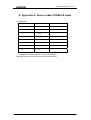
RC953-8FE16E1 Inverse Multiplexing Ethernet Gateway User manual Raisecom Technology Co., Ltd (06/2006) Contents 1. Cautions.............................................................................................................. 1 2. Overview............................................................................................................. 2 2.1. 2.2. 2.3. 3. Parameters ......................................................................................................... 4 3.1. 3.2. 3.3. 3.4. 3.5. 3.6. 3.7. 4. Main features ........................................................................................... 2 Part number specification......................................................................... 3 Dimension ................................................................................................ 3 Basic configuration................................................................................... 4 Ethernet interface parameters.................................................................. 4 E1 interface parameters........................................................................... 4 CONSOLE interface parameters.............................................................. 5 SNMP network management interface parameter ................................... 5 Power supply ........................................................................................... 5 Ambience ................................................................................................. 5 How to use.......................................................................................................... 6 4.1. 4.2. Front panel explanation............................................................................ 6 Rear panel explanation ............................................................................ 7 5. Typical application .............................................................................................. 9 6. Installation & Preparation.................................................................................. 10 6.1. 6.2. Preparation before Installation ............................................................... 10 Installation .............................................................................................. 10 6.2.1. Cable preparation.......................................................................... 10 6.2.2. Connect the fast Ethernet port .......................................................11 6.2.3. Connect the SNMP network management port ..............................11 6.2.4. Connect the CONSOLE port ..........................................................11 6.2.5. Power on ........................................................................................11 6.2.6. Service configuration..................................................................... 12 7. Q & A ................................................................................................................ 13 8. Appendix A: How to make CONSOLE cable..................................................... 14 9. Appendix B: Abbreviations ................................................................................ 15 Raisecom Technology Co., Ltd 1. Cautions Please read the following notices carefully before installing and using the device, Raisecom does not respond to any loss that caused by violating safety notice. This series product is integrated device that has precise elements, please avoid violent shakes and impacts, and do not disassemble or maintain the device yourself. If it is required, please do it under the guide of our technical staff following in the steps of anti static. Please contact us if there is any need. There must be grounding protection for the sake of safety; do not disassemble the device yourself, we regard it as you waiver your rights of repair guarantee. 1 Raisecom Technology Co., Ltd 2. Overview RC953-8FE16E1 is an Inverse Multiplexing Ethernet Gateway that delivers Ethernet services over existing TDM transportation network. It can be deployed in central site for aggregating subscribers or in customer premises enabling Inverse Multiplexing for enlarging much more bandwidth. RC953-8FE16E1 provides 8 Ethernet ports and 16 E1 ports (both balanced and unbalanced) for subscribers and functions as a bridge between IP-based network and leased circuits. Additionally its advanced features such as automatic E1 link adjustment, Ethernet port trunking (Link Aggregation for redundant Ethernet Access) and redundant power supply provide our carriers a cost-effective, flexible and reliable solution for high-quality Ethernet Service delivery by using TDM network resources. 2.1. Main features z z z z z z Provide 16 E1 interfaces and the E1 working mode can be Single E1 Mode and Inverse Multiplexing Mode; Provide 8 fast Ethernet interfaces, which support auto-negotiation, auto-MDI/MDIX, 10M/100M, half/full duplex and IEEE802.3x flow control; HDLC-over-E1 encapsulation In single E1 mode: Support both framed and unframed E1 mode Only one E1 link in each transmission channel With RC952 in remote sites in hub-and-spoke topology In E1 Inverse Multiplexing mode: Adopt frame-interleave multiplexing to realize the transportation of Ethernet over multiple E1 With RC953-FE4E1/8E1 in remote sites in hub-and-spoke topology E1 wire sequence auto-sensing The maximum relative latency of E1 line is +/-16ms Automatically adjust the E1 link capacity of transmission channel if one or more E1 link fails Only support framed E1 (PCM31, FAS+CRC4 by default), CRC auto-negotiation and is configurable Ethernet switching function: 4096 MAC address Transparently forward BPDU, GMRP, GVRP and IGMP packets Maximum Transmission Unit: 1536 bytes Ethernet port trunking (Link Aggregation for redundant Ethernet Access) 2 Raisecom Technology Co., Ltd z z z z z z z z E1 loop back and BERT function Complete E1 line indicators on front panel E1 interface type: 2 DB37 for both balanced and unbalanced interfaces SNMP, CONSOLE and Telnet management (any of the 8 fast Ethernet can be SNMP network management interface) and support local and remote field firmware upgrade. 1U chassis and can be installed in 19’’ rack Redundant power supply Power consumption <20W (at maximum load) Working temperature: -5℃- 50℃ 2.2. Part number specification Part number: RC953 - A 8FE16E1 B - C BL AC Blank DC RC953: inverse multiplexing Ethernet gateway A field: 8FE16E1 indicates there are 8 fast Ethernet ports and 16 E1 ports. B field: E1 connector type: BL or blank. Blank: 75ohm unbalanced BNC connector. BL: 120ohm balanced RJ-45 connector. C field: power supply is AC or DC *24V DC is customized. 2.3. Dimension International standard 19’’ 1U structure: 430mm(W)×44.45mm×(H)×266mm(D) 3 Raisecom Technology Co., Ltd 3. Parameters 3.1. Basic configuration z z z Main circuit: 8 fast Ethernet ports, 16 E1 ports. Power supply: two power supply modules, 90-264V/AC or -36V- -72V/DC. Management interface: CONSOLE, SNMP network management interface (utilize any of the 8 fast Ethernet ports). 3.2. Ethernet interface parameters z z z z z Speed: 10/100M auto-negotiation Connector: RJ-45 IEEE802.3 compliant IEEE802.3x flow control AUTO-MDI/MDIX 3.3. E1 interface parameters 75ohm unbalanced or 120ohm balanced E1 connector. 16 E1 ports, the first 8 E1 ports utilize one DB37 and the second 8 E1 ports utilize another DB37. z Bit rate: 2048Kbps±50ppm. z Line coding: HDB3. z Input impedance: 75ohm unbalanced. z Electric characteristic: ITU-T G.703 compliant. z Frame structure: ITU-T G.704 compliant z Jitter: ITU-T G.823 compliant. z In single E1 mode: E1 interface supports both framed and unframed E1 mode and can be configured through software (unframed mode by default). In framed E1 mode, support N*64k sub-rate access and FAS (PCM31 without CRC4), FAS+CRC4 (PCM31 with CRC4), FAS+CAS (PCM30 without CRC4) and PAS+CRC4+CAS (PCM30 with CRC40). In E1 Inverse Multiplexing mode: Adopt frame-interleave multiplexing to realize the transportation of Ethernet over multiple E1. E1 wire sequence auto-sensing The maximum relative latency of E1 line is +/-16ms Automatically adjust the E1 link capacity of transmission channel if one or more E1 link fails Only support framed E1 (PCM31, FAS+CRC4 by default), CRC auto-negotiation z z z 4 Raisecom Technology Co., Ltd z z z z z and is configurable There are three status indicators for each E1 circuit: LOS: Loss of Signal (local) LAL: local E1 general alarm, including AIS(alarm indication signal), LOF( Loss of Frame), CRC(Cyclic Redundancy Check) RAL: remote E1 alarm, including LOS, AIS, LOF, CRC Local and remote E1 loop back E1 BERT (bit error rate tester) function Traffic counter provides an effective E1 link monitoring by statistics collection of Rx, TX, total and error packets amount on E1 port. 4M Bytes buffer for each Ethernet port to avoid packet loss 3.4. CONSOLE interface parameters ● ● ● Connector type: RJ-45 RS232 compliant Rate: 9600bps 3.5. SNMP network management interface parameter ● Utilize one of the 8 fast Ethernet ports, please refer to chapter 3.2 3.6. Power supply ● ● Redundant power supply. Voltage range: -48VDC, –36V - -72V 220VAC, 90V- 264V ● Power consumption: <20W 3.7. Ambience ● ● Temperature: -5℃-50℃ Relative Humidity: ≤90%(35℃) 5 Raisecom Technology Co., Ltd 4. How to use 4.1. Front panel explanation RC953-8FE16E1 1 2 3 5 4 7 6 9 8 Figure 4-1 Front Table 4-1 Explanation of RC953-8FE16E1 front panel N o. Explanati on 1 Grounding SYS 2 and Indicator color Green Description SYS, Flashing indicates CPU work normally. PWR, ON indicates equipment is powered on. PWR indicator PWR1 and Green PWR1, ON indicates the first power supply works normally PWR2, ON indicates the second power supply works normally. PWR2 Explanation of PWR, PWR1and PWR2 combination: PWR PWR1 PWR2 ON ON ON Explanation The two power supply modules and main circuit works normally. ON ON OFF The first power supply works normally, the second works abnormally and the main circuit works 3 normally. ON OFF ON The first power supply works abnormally, the second works normally and the main circuit works normally. OFF ON ON The first power supply works normally, the second works normally but the main circuit works abnormally. OFF ON OFF The first power supply works normally, the second works abnormally but the main circuit works abnormally. 6 Raisecom Technology Co., Ltd OFF OFF ON The first power supply works abnormally, the second works normally but the main circuit works abnormally. OFF OFF OFF Not powered on or neither of the power supply module works normally. 4 CONSOL Local management port which connects to management PC E Green/or Ethernet 5 ange 1-8 fast Ethernet ports. And each port has two indicators: LNK/ACT (green) and 100M indicator (orange). port LNK/ACT, flashing indicates data is being received; indicator 100M, ON indicates the speed of fast Ethernet is 100M and OFF indicates 10M. Red Each E1 circuit has three indicators, from top to bottom are: (Top) LOS: Loss of Signal (local). 6 1-8 (Middle) LAL: local general alarm, including AIS (alarm indication signal), E1 LOF (loss of frame), CRC (cyclic redundancy check). indicator (Bottom) RAL: remote general alarm, including LOS, AIS, LOF, CRC. *note: when both LOS and LAL are ON at the same time, this indicates GID alarm. 7 1-8 E1 DB37 connector which connects with special cable. connector Red Each E1 circuit has three indicators, from top to bottom are: (Top) LOS: Loss of Signal (local). 8 9-16 E1 indicator (Middle) LAL: local general alarm, including AIS (alarm indication signal), LOF (loss of frame), CRC (cyclic redundancy check). (Bottom) RAL: remote general alarm, including LOS, AIS, LOF, CRC. *note: when both LOS and LAL are ON at the same time, this indicates GID alarm. 9 9-16 E1 connector DB37 connector which connects with special cable. 4.2. Rear panel explanation ON OFF 1 Figure 4-2 rear panel of RC953-8FE16E1 7 2 Raisecom Technology Co., Ltd Table 4-2: explanation of RC953-8FE16E1 rear panel Numb er Explanation Power 1 Description supply switch for the ON/OFF. device 2 Power supply connector Two types, AC and DC. 8 Raisecom Technology Co., Ltd 5. Typical application Figure 5-1 point-to-point topology Figure 5-2 point-to-multi point topology 9 Raisecom Technology Co., Ltd 6. Installation & Preparation 6.1. Preparation before Installation Please check if the models and part numbers are in consistence first, and also check if the equipments are damaged. There must be drying process if the equipment is damped. Please follow the following steps when install and use this equipment: ● Carefully read this manual ● Prepare all kinds of the cable. Ensure that they are not short-circuited. Refer to Appendix A for cable making. ● Fix and install the equipment ● Connect E1 cable ● Configure the equipment according to the configuration guide ● Use the equipment correctly 6.2. Installation 6.2.1. Cable preparation The following cables need to be prepared: Table 6-1 Cable specification for RC953-8FE16E1 connectors Connector Cable specification 10/100Mbps Electrical Ethernet connector Cat. 5 100Base-T UTP, and the maximum (SNMP management length is 100m (prepared by customers) connector) Please order the 2 cables separately Connector cable for For 75ohm unbalanced E1 connector: one end of E1 (the first 8 E1 the cable is DB37 and the other end are 8 utilize one DB37 75ohm unbalanced BNC connectors; connector and the For 120ohm balanced E1 connector: one end of second 8 E1 utilize the cable is DB37 and the other end are 8 one DB37 connector) balanced RJ-45 connectors; Provide one CONSOLE cable. CONSOLE connector Please refer to the appendix for how to make CONSOLE cable. AC power supply: provide one AC power supply Power supply cable. connector DC power supply: provide one DC power supply cable. 10 Raisecom Technology Co., Ltd 6.2.2. Connect the fast Ethernet port Connect one end of the Cat. 5 UTP cable with Ethernet router/switch and one end of the cable with the fast Ethernet port of RC953-8FE16E1. The LNK/ACT indicator will be ON after correct connection. 6.2.3. Connect the SNMP network management port Connect one end of the Cat. 5 UTP cable with management PC and one end of the cable with the fast Ethernet port of RC953-8FE16E1. The LNK/ACT indicator will be ON after correct connection. 6.2.4. Connect the CONSOLE port ● ● ● Connect the RJ-45 connector of CONSOLE cable with the CONSOLE port on the front panel. Connect the DB9 connector of CONSOLE cable with the PC serial port. Start the HyperTerminal program and configure the COM port properties as follows: ● Configure RC953-8FE16E1 according to software configuration guide 6.2.5. Power on If power supply is DC –48V, first connect middle end to PGND. Turn off Power Supply, 11 Raisecom Technology Co., Ltd connect “-48V” end with the lower electric level cable, “0V” end with higher electric level cable. Make sure no reverse connection, or no short circuited, and then turn on power. When Power Supply is turned on, the PWR indicator should be ON. 6.2.6. Service configuration Please refer to the command notebook and configuration guide of RC953-8FE16E1 for the service configuration. 12 Raisecom Technology Co., Ltd 7. Q & A If there are any problems during installation and using, try the following proposals. If the problems still can not be solved, please contact distributors/agents for help. ● If PWR, PWR1 and PWR2 are all OFF Please check if power supply cable is connected and then check if the Power Supply Board works normally *Explanation of PWR, PWR1and PWR2 combination: PWR PWR1 PWR2 Explanation ON ON ON The two power supply modules and main circuit works normally. ON ON OFF The first power supply works normally, the second one works abnormally ON OFF ON and the main circuit works normally. The first power supply works abnormally, the second one works normally and the main circuit works normally. OFF ON ON The first power supply works normally, the second one works normally but the main circuit works abnormally. OFF ON OFF The first power supply works normally, the second one works abnormally but the main circuit works abnormally. OFF OFF ON The first power supply works abnormally, the second one works normally but the main circuit works abnormally. OFF OFF OFF Not powered on or neither of the power supply module works normally. ● E1 LOS indicator is ON Answer: Loss of receiving signal occurs at e1 port. Check whether E1 cable is connected correctly; if there is still LOS alarm please change the E1 cable otherwise there is something wrong with the equipment. ● Ethernet LINK indicator OFF Answer: please check if the UTP cable is broken off first and then check if the equipment that connects with RC953-8FE16E1 works normally. Please make sure that the correct Ethernet cable is used. 13 Raisecom Technology Co., Ltd 8. Appendix A: How to make CONSOLE cable Pin definitions: RJ45 pins Function DS9 pins 1 NC - 2 DSR# 6 3 RxD 3 4 GND 5 5 GND 5 6 TxD 2 7 DTR# 4 8 NC - “-” indicates the relative RJ45 pin is not connected (NC). DB9 pins which are not in the list are not connected (NC). 14 Raisecom Technology Co., Ltd 9. Appendix B: Abbreviations EoPDH PDH Ethernet over PDH Pseudo-synchronous Digital Hierarchy. 15 Raisecom Technology Co., Ltd @2006 Raisecom Technology Co., Ltd. All trademarks are the property of their respective owners. Technical information may be subject to change without prior notification. 16