1
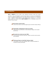
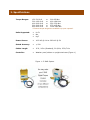
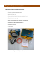
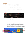
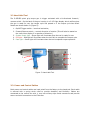
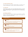
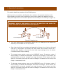
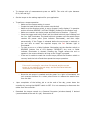
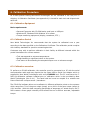
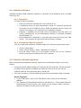
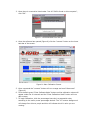
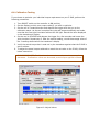
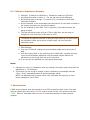
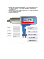
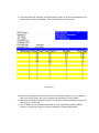
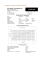
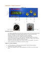
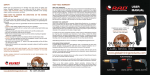
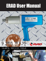
ERAD User Manual
Quality, Service, Value
TABLE OF CONTENTS
1. Introduction....................................................................................................1
2. Specifications..................................................................................................2
3. System Component Description.........................................................................3
3.1. Controller................................................................................................ 4
3.2. Hand Held Tool.........................................................................................5
3.3. Power and Control Cables...........................................................................5
3.4. Serial Communication Cable.......................................................................6
3.5. Software CD.............................................................................................6
3.6. Calibration Certificate................................................................................6
4. System Setup.................................................................................................6
5. Operation Instructions......................................................................................8
6. Calibration Procedure.....................................................................................10
6.1. Calibration Equipment..............................................................................10
6.2. Calibration Period....................................................................................10
6.3. Calibration overview................................................................................10
6.4. Calibration Software................................................................................11
6.4.1. Installation...................................................................................11
6.4.2. Uninstalling E-RADCal program........................................................11
6.5. Calibration Software Operation..................................................................11
6.6. Calibration Testing..................................................................................14
6.7. Calibration Adjustment.............................................................................15
7. Data Retrieval...............................................................................................15
7.1.
Data Retrieval Operation.......................................................................16
Appendix
Appendix
Appendix
Appendix
Appendix
A – Sample Calibration Certificate.....................19
B – Option 1 Operation....................................20
C – Option 2 Operation....................................21
C – Option 3 Operation....................................23
D – Contact Information..................................24
IMPORTANT
DO NOT OPERATE THE TOOL BEFORE READING THIS USER MANUAL.
IF BREAKDOWN, MALFUNCTION OR DAMAGE OCCURS, DO NOT
ATTEMPT TO REPAIR. CONTACT NEW WORLD TECHNOLOGIES INC.
OR YOUR LOCAL DISTRIBUTOR IMMEDIATELY.
IMPORTANT
WHEN USING A POWER PLUG ADAPTER, MAKE SURE THE EARTH
GROUND PIN IS PRESENT AND CONNECTED IN THE ADAPTER. NEW
WORLD TECHNOLOGIES INC. DOES NOT RECOMMEND REAPLCING
THE SUPPLIED POWER CORD. IN THE EVENT THE POWER CORD IS
REPLACED MAKE SURE THE NEW POWER CORD HAS AN EARTH
GROUND PIN.
1. Introduction
RAD E SERIES are the world’s most advanced electronic pistol grip torque
wrenches. They are designed to provide a high degree of accuracy and repeatability
using our patented, legendary gear box design and the precision of an electronic
motor. Capable of data collection, angle measurement, accuracy of +/- 3% and
torque values up to 4000 ft/lbs, RAD E-SERIES offer an affordable solution for
electronic bolting needs.
Push-button select torque
Fast and convenient error-free digital single increments torque settings
Lightweight and Ergonomic pistol grip design
Advanced low-profile handle to reduce operator fatigue and increase
productivity
Extremely low noise level only 75db
World’s quietest extreme torque gun, ideal for sensitive environments
and standards
LED Green (Pass) or Red (Fail) indicator lights
Unmistakable visual signal indicates status of torque procedure for
maximum accuracy and speed
2. Specifications
Torque Ranges:
150-700 lb-ft
or
300-1200 lb-ft
or
400-2000 lb-ft
or
500-3000 lb-ft
or
800-4000 lb-ft
or
*Custom torque ranges
200-950 Nm
400–1600 Nm
550-2700 Nm
675-4050 Nm
1000-5400 Nm
are available up upon request*
Units Supported:
Lb-Ft
Nm
Kg.F
Power Source:
115V AC @ 10A or 220V AC @ 5A
Stated Accuracy:
+/-3%
Cables Length:
15 ft / 4.5m (Standard), 20 ft/6m, 25 ft/7.6m
Controller:
Weather proof pelican or upright steel case (Figure 1)
Figure 1 : E-RAD System
3. System Component Description
E-RAD System (Figure 2) includes the following:
• Controller (weatherproof or steel case)
• Hand Held Torque Gun
• Power and Control Cables (attached to hand held tool)
• Reaction Arm (w. snap ring)
• Serial Communication Cable (calibration / data retrieval)
• Calibration and Data Retrieval software CD
• Calibration Certificate
• User Manual
Figure2: E-RAD System Components
3.1 Controller
Below in Figure 3 are all of the input/output ports in the E SERIES.
1. Main Input Power Connector – (115V AC) or (220V AC).
2. Ethernet Communication Port – Ethernet to Serial Port Cable Provided to
connect your E-RAD to a PC for calibration and data retrieval.
3.
Connectors for Pistol Grip Torque Gun – Military style connector provide a
protected interface between the Controller and the Hand Held Tool.
3
1
2
Figure 3: Controller Connections
Below in Figure 4 the user interface is outlined
1. 3 Button Touch Pad Overlay – Provides the user the ability to
increase/decrease torque / angle and change the units of measurement.
2. LCD Display – Visual feedback of the torque setting, torque achieved,
preset angle and direction of rotation.
3. Main Power Switch – This switch will turn the E-RAD on / off.
4. Green Power Light – This light will illuminate when the power is turned on.
3
2
4
1
Figure 4: User Interface
3.2 Hand Held Tool
The E-SERIES pistol grip torque gun is trigger activated with a bi-directional forward /
reverse switch. On the back of the gun housing is a 3 LED light display which notifies when
the gun is ready for use, the torque cycle has passed or if the torque cycle has failed.
Details are shown below in (Figure 5):
1. On/Off Trigger switch – hand tool activation;
2. Forward/Reverse switch – controls direction of rotation (This will also be stated on
the control box display if in question of direction.)
3. System Ready light – Green light will illuminate when the tool is ready for use
4. Fail light – Red light will illuminate when the tool fails to complete the torque cycle
5. Pass light – Green light will illuminate when the tool completes torque operation.
3
2
4
1
5
Figure 5: Hand Held Tool
3.3. Power and Control Cables
Both power and control cables are hard wired from the factory to the hand tool. Each cable
is secured with a spring strain relief to provide durability and flexibility. Cables are
connected to the control box with ¼ turn lock military style metal connectors and provide
secure and solid connection to the Controller.
3.4. Serial Communication Cable
This cable enables serial communication interface between your computer and the
Controller via standard RS232. This cable is required for calibration and data retrieval.
3.5. Software CD
E-RAD software CD contains 2 custom made windows based programs for the E-RAD
system: • E-RAD Calibration software – enables Lab/Field calibration of the hand held tool •
E-RAD Data Retrieval Software – enables the retrieval of up to 750 successful torque
operations
3.6. Calibration Certificate
Each unit is calibrated with compliance to ISO 10012 using equipment that is calibrated
according to known industry accepted standards traceable via NIST standards. See
appendix A for a Calibration Certificate Sample.
4. System Set-up
!
CAUTION
!
CAUTION
!
CAUTION
Before plugging in main power cord or Hand Held Tool cables; make
sure the main power switch is in the OFF position. Failure to comply
may result in equipment failure or equipment damage.
Do not force the connectors onto the Controller. Failure to comply
may result in damage to the connectors
Never lift the tool by the cables. Do not pull excessively on the
cables or drag the Controller by pulling on the cables. Failure to
comply may result in damage to equipment.
!
CAUTION
**Before powering up the unit perform the following steps**
1. Align control cable notch to the notch in the controller. Push the connector in forward
and turn clock wise at least ¼ turn until the plug locks into the connector on the
case;
2. Align power cable notch to the notch in the controller. Push the connector in forward
and turn clock wise at least ¼ turn until the plug locks into the connector on the
case; 3. Connect main AC power plug to an appropriate AC power source (115V AC or 220V
AC according to the model); 4. Make sure serial communication cable is disconnected.
!
CAUTION
Make sure that all connectors are secured prior to turning the power
switch ON. Failure to comply may result in equipment failure and/or
equipment damage.
5. Operation Instructions
This section details the operation of the E-RAD system.
When the tool is in operation, the Reaction Arm rotates in the opposite direction to the
Output Square Drive and must be allowed to rest securely against the adjacent bolt or a
nearby solid object that is on the same plane as the bolt that you are working on (Figure 6).
WARNING: ALWAYS KEEP HANDS CLEAR OF THE REACTION ARM WHEN THE
TOOL IS IN USE OR SERIOUS INJURY WILL RESULT.
Reaction Point
Clockwise Operation
FIG
Counter
Clockwise Operation
Figure 6: Reaction Arm
•
Turn main power switch to ON position. When the Green ON light on the control box
Assembly is illuminated the unit is powered.
•
Once internal self test is completed and passed, the System Ready light on the hand
held tool is illuminated. The display will flash model and firmware version for 2
seconds, then displays on the top row, last used torque setting and on the bottom
row and the actual torque reading.
•
To increase torque setting, press on the INCREASE arrow. If maximum value of
torque setting is reached, the displayed value does not change. If the buttons are
pressed briefly, the torque changes by a single increment. If the buttons are held
down for 3 seconds, the torque will start to change in increments of 10 counts, and
finally in increments of 100.
•
To decrease torque setting, press on the DECREASE arrow. If minimum value of
torque setting is reached, the displayed value does not change. If the buttons are
pressed briefly, the torque changes by a single increment. If the buttons are held
down for 3 seconds, the torque will start to change in increments of 10 counts, and
finally in increments of 100.
•
To change units of measurements press on UNITS. The units will cycle between
Ft.Lb, Nm and Kg.F.
•
Set the torque to the setting required for your application.
•
To perform a torque operation:
o Make sure the torque setting is correct
o Couple the hand held tool with socket onto the bolt
o Make sure the direction switch is set to forward (verify display if in question
as this will show REVERSE / ACTUAL TORQUE (forward) on the bottom row)
o Make sure reaction arm has a proper and safe point of reaction (Figure 6)
o Press the trigger and hold it down until the hand held tool stops rotating and
the Pass light illuminates. The hand held tool operates until the actual torque
reaches the preset value (Pass indicator Illuminated), and then stops
automatically. If the Trigger is released before the set torque is reached, or
the tool fails to reach the required torque, the Fail indicator light is
illuminated.
o To clear an error or a failed indicator illumination set the direction switch to
REVERSE (bottom line of LCD displays “REVERSE”) Any error or failed
indicator illumination is cleared; Pressing the Trigger causes the tool to
operate in the reverse direction as long as the Trigger is pressed.
o If the tool is unable to reach the correct torque, switch the Direction switch to
reverse, back the bolt off and then repeat the torque operation.
IMPORTANT NOTE:
If the tool is running for more than 20 seconds and the correct
torque is not reached, the tool stops, and the Red Failed indicator
illuminates on the handgrip.
o
Once the set torque is reached and the green Pass light is illuminated, the
tool reverses direction for a short pulse motion to release the reaction arm
from the bolt.
•
Upon completion of the bolting job or at the end of the day, power down the
controller by turning the ON/OFF switch to OFF. It is not necessary to disconnect the
cables from the controller.
•
Download the torque records to a Personal Computer (windows based) if desired
(recommended at the end of a job). See section 8.
6. Calibration Procedure
All E-RAD systems leaving New World Technologies Inc are calibrated in the Lab prior to
shipping. A Calibration Certificate (see appendix A) is issued for each tool and shipped with
each tool.
6.1. Calibration Equipment
Basic requirements:
• Personal Computer with CD-ROM and a serial port or USB port.
• Windows NT, Windows 2000 Windows XP or newer.
• Torque measuring equipment (display, transducer, ETC.)
6.2. Calibration Period
New World Technologies Inc recommends that the system be calibrated once a year
according to the date specified on the Calibration Certificate. The calibration period complies
with industry standards for precision measuring devices.
Customers may wish to perform calibration in their facility at different intervals within the
period listed above for various reasons:
• Tool was exposed to extreme temperatures
• Rough handling or significant shock to the system
• Tool seems to be exceeding the accepted torque error or tolerance margin.
6.3. Calibration overview
To perform an E-RAD calibration, the controller must be connected to a PC with the serial
communication cable and may require the Key Span USB to Serial Port Adapter which is
supplied by New World Technologies with every E-SERIES tool. The PC must have the ERAD Cal calibration software installed prior to calibration which is also provided by New
World Technologies (See 6.4.1). The hand held tool must be coupled to a suitable test
fixture fitted with a torque sensor / transducer.
The E-RAD Cal software allows us to calibrate 11 different calibration points on the systems
which range from 7% of the guns output (amps) up to 100% of the guns output (amps) in
10% intervals. With this data comparing percentage of amperage vs. actual torque, the ERAD creates a linear graph internally which allows the tool to deliver accurate, repeatable
torque.
6.4. Calibration Software
Standard windows based calibration software is required for the calibration and is included
with every tool.
6.4.1. Installation
To install E-RAD Cal software:
•
•
•
•
Place the E-RAD Cal software CD in the CD-Rom drive;
If installation does not start automatically, select my computer and double
click (open) on the CD-ROM (D) drive. Select and double click the “setup” file
(picture of computer); this will launch the installation program.
Software is installed into the folder that is specified by the user and if no
folder is specified this will be automatically saved to C:\Program Files\New
World\ERadCal_V2.
Once installation is completed, in your start menu there will be shortcut “New
World”. This shortcut will open the E-RAD calibration software.
6.4.2. Uninstalling E-RAD Cal program
If for any reason the calibration software needs to be removed, follow these steps:
•
•
•
Click on “Start Menu”
Select “Control Panel” • Select “Add/Remove Programs”
Find and select E-RAD Cal in the program list and click on the “Remove”
Button to remove the software from your computer.
6.5. Calibration Software Operation
Before launching the calibration software, make sure the calibration system is set up as
follows:
•
•
Connect the Serial Cable between the computer and the controller. Use the supplied
Key Span USB to Serial Port adapter provided with the tool if you are using a
computer that has only USB ports and no Serial port
Turn the Controller on with the hand held gun and communication cable connected.
On the Computer:
1. In your Start Menu, click on the “New World” tab to open up the calibration
software.
2. The software will automatically search for the Mint Drive. If the system does not
automatically find a Mint Drive, click “search” on the screen in figure 7 and the
program will detect the Mint Drive on the E-RAD.
3. Once there is a controller listed under “List of E-RAD’s found on this computer”,
click “OK”.
Figure 7: Communication Port Set-up
4. Once the software has opened (Figure 8) click the “connect” button on the lower
task bar of the screen.
Figure 8: Main Calibration Screen
5. Once connected the “connect” button will turn orange and read “disconnect”
(Figure 9)
6. Click the dark green “Enter Calibrate Mode” button and the calibration values will
appear under the % intervals and the “Enter Calibration Mode” button will turn
dark orange.
7. To begin calibration, click the percentage intervals in a sequential order,
according to the motor power percentage desired. The “%” buttons background
will change from blue to purple and this will indicate which % value you are
running.
Figure 9: Start Calibration Screen
8. Select 7%, motor load to limit motor power output to 7%.
9. Make sure direction switch on the tool is in Forward position.
(REVERSE does not appear on the controller display VERIFY THIS)
Depress the trigger on the tool. Do not let the trigger go until the tool stops
automatically and displays the green passed light.
10. If the tool is stopped and the green Pass light on the tool is not illuminated or the
Fail red light is illuminated, place the direction switch in REVERSE and depress
the trigger for a couple of seconds. Repeat step 9.
11. Record the reading on the transducer’s display, take a couple more readings to
make sure that the readings are in the same value range and take the average of
the values.
12. In the Calibration Torque table, place the cursor in the text box underneath the
label value of 7% and type in the average torque value calculated in the previous
step. Press Enter.
Attention:
Enter must be pressed after every entry, otherwise the value will not be recorded.
13. Repeat steps 8 to 12 for the other settings of 10% - 100% load.
14. Click on “Save Settings”. This means that the controller communicated the
calibration values to the computer and the values are saved.
15. To print out a copy of the calibration numbers for traceability, click on the purple
“Print” button.
16. Turn ON/OFF switch on the controller to OFF position;
17. Disconnect Serial Cable from the controller.
6.6. Calibration Testing
If you choose to optimize your individual torque requirement on your E-RAD, perform the
following procedures.
1. Turn ON/OFF switch on the controller to ON position;
2. Set the display to which ever torque value(s) you wish to optimize.
3. Set the tool in Forward direction and depress the trigger with the gun on the
calibration stand. Let the tool complete the cycle and stop automatically and make
sure that the Pass light illuminates without the fail light. Record the value displayed
on the transducer’s display.
4. Set the tool in REVERSE and depress the trigger for a few seconds and loosen the
joint simulator. Repeat step 3. After the second reading, record the average value of
the 2 readings observed on the transducer’s display.
5. Verify the actual torque that is read out by the transducer against what the E-RAD is
set to achieve.
6. To adjust the actual torque achieved to match the set value on the E-RAD, follow the
below instructions.
IMPORTANT NOTE: If calibration values are increased, actual torque applied
decreases. If calibration values are decreased, actual torque applied increases
Figure 10: Adjust Values
6.7. Calibration Adjustment Example
1. Example: E-RAD set to 1800 ftlbs = Transducer reads out 1750 ftlbs.
2. All though this value is within +/- 3%, we can narrow this difference.
3. By following steps 1 through 7 in section (6.5) re-connect to the E-RAD
calibration software.
4. Once connected, in the percentage intervals find the % value that is closest to
the torque value that you are trying to adjust.
5. For our example of 1800 ftlbs, 70% in (figure 9) is the value that we are
going to adjust.
6. To bring the actual torque up from 1750 to 1800 ftlbs, we are going to
change the 70% value from 1790 down to 1760.
Remember the general rule that to bring a torque value up, we must lower
the calibration value and to lower a torque value, we must raise the
calibration value.
7. Save Settings.
8. Turn your E-RAD off, unplug the communication cable and re-start your ERAD.
9. With the torque value on the controller set to 1800 ftlbs, complete a torque
cycle on the calibration stand and verify the actual torque read by the
transducer to the torque value set on the controller.
10. If you are still not satisfied you may repeat these steps.
Notes:
1. Generally for every (1) calibration value you change, the actual output torque will be
adjusted by 2. For Example…
2. If the value you are trying to change is right in between to percentage intervals
(20% / 30%), make adjustments to both percentage values.
NOTE: By adjusting both of these values, this may effect the accuracy of other
torque settings on your E-RAD.
7. Data Retrieval
E-RAD torque systems store the records of up to 350 successful torque cycles. The data
retrieval system does not record “FAILED” torque cycles and will only record cycles that
“PASS”. Below is a detailed outline on how to install and operate your data retrieval
program.
Minimum Requirements:
1.
2.
3.
4.
Personal Computer with CD-ROM and a serial port or USB port.
Windows NT, Windows 2000 Windows XP or newer
E-RAD Calibration software already installed on the same PC;
Microsoft Excel installed on the same PC.
The software does not require installation but the following setup must be performed:
1. Insert E-RAD Calibration Software CD in to the CD-ROM drive;
2. Select my computer and double click (open) on the CD-ROM drive. Select “E-RAD
Data V2.003 Setup” folder and then double click the “Setup” file.
3. From here the setup will guide you through installing the software onto your
computer.
4. After the setup is complete, unless otherwise specified the Data Retrieval
Software will be installed in My Computer/Program Files/E-RAD-Data. From here,
copy the short cut of the E-RAD Data Logger and paste this onto your desktop for
easy accessibility.
7.1. Data Retrieval Operation
1.) Before opening the E-RAD Data Retrieval Software, connect your E-RAD Control
Box to your computer using the Serial Communication Cable and Key Span USB to
Serial Adapter if necessary. Turn the E-RAD “ON”.
2.) Open the Data Retrieval program.
3.) Once open the below screen will automatically detect which port and baud rate
your E-RAD is connected to (Figure 1A). Once detected, the COMM PORT SETUP will
display your computers connection to the E-RAD (Figure 1B).
(Figure 1A)
(Figure 1B)
1.) Once the Data Retrieval main screen appears, fill out your desired information
into the screen (Operator ID, Job Number, Job Location, Completion Date,
Completion Time).
2.) Click “Connect to E-RAD” on the interface and the “RED” Disconnected will turn
“GREEN” and display Connected.
3.) Click on “Download Data”.
(Figure 10)
4.) The Data Retrieval Software will automatically open up an excel spreadsheet and
download all of the stored data. This will take approx 30 seconds.
(Figure 11)
5.) Save this file under any file name and in your desired location in your computer
and your bolting specs are now recorded and accessible in your system.
6.) After the download is complete, return to the Data Retrieval Software (Figure 10)
and click on “Clear Data”.
7.) Your E-RAD has now transferred all data to your personal computer and the
memory is clear and ready for another sequence of bolting application
Appendix A – Sample of Calibration Certificate
Appendix B – Option 1 Operation
Selector switch provides the ability to program up to 8 torque settings, 1 per switch
position. These settings are usually the most common settings used and allow a fast switch
between torque settings instead of dialing up/down the torque each time a different torque
is required. This option includes a lockout key switch which enables/disables torque changes
via the keypad and switch position programming.
Programming a switch position:
1.
2.
3.
4.
Place the switch knob to the position to be programmed;
Turn the key to the right (in this position key removal in not allowed);
Press increase or decrease to reach the torque setting required;
if more position are required to be programmed, turn the switch know to the next
position and repeat step 3;
5. After the last position programming turn the key left and remove the key;
6. Positions are now programmed and ready to use.
Note:
When the key is removed the keypad is disabled, pressing on any of the buttons will
have no effect.
Appendix C – Option 2 Operation
Standard Features:
All E-RAD torque/angle pre-sets will come pre-set to zero from the manufacturer and
are to be adjusted to the desired settings by the user. This is outlined below.
If the angle is set to zero than no angle movement will take place.
If the torque is set to zero, no initial torque will take place and the tool will only
perform the programmed angle movement only. The tool will walk up and seat the
reaction arm and then complete the angle movement.
If both the torque and angle are set to zero the tool will not operate.
Figure 1.1 = User Interface (above)
•
•
•
•
•
•
•
•
This indicates the initial torque value that the E-RAD will achieve before initializing
into the angle movement.
(2) This will indicate the actual torque applied by the E-RAD in your initial torque
cycle.
(3) This will indicate which unit of measurement your E-RAD is operating in. This
system can operate in ft.lbs / Nm / or KgF.
(4) This arrow will indicate which value or setting you would like to adjust. In Figure
1.1 this arrow is positioned to the right of the FP (ft.lbs) which means that by
pressing the increase / decrease buttons, you will be able to scroll through the
different units of measurement.
To change the position of the arrow which will allow you to adjust either the initial
torque, units of measurement, or angle movement, press the “Units” button (7) to
move this arrow to the right of your desired feature that you would like to adjust.
(5) This will indicate what angle movement the E-RAD is programmed to perform
after the initial torque cycle. Once the cycle is complete the E-RAD will display angle
move done.
(6) This increase / decrease button allows the user to increase torque, angle or
change the unit of measurement.
(7) The “units” button allows the user to scroll through which feature they would like
to adjust. This arrow is explained in (4) above.
Appendix D – Option 3 Operation
(Figure 1.1)
(Figure 1.2)
(Figure1.3)
Standard Features:
All E-RAD torque/angle pre-sets will come pre-set to zero from the manufacturer and
are to be adjusted to the desired settings by the user. This is outlined below.
Positions (1 through 8) will have the option of torque and angle.
If the angle is set to zero than no angle movement will take place.
If the torque is set to zero, no initial torque will take place and the tool will only
perform the programmed angle movement only. The tool will walk up and seat the
reaction arm and then complete the angle movement.
If both the torque and angle are set to zero the tool will not operate. This can be
used as a safety lock out setting on the selector switch.
Figure 1.1 = User Interface
•
•
(1) This indicates the initial torque value that the E-RAD will achieve before
initializing into the angle movement.
(2) This will indicate the actual torque applied by the E-RAD in your initial torque
cycle.
•
•
•
•
•
•
(3) This will indicate which unit of measurement your E-RAD is operating in. This
system can operate in ft.lbs / Nm / or KgF.
(4) This arrow will indicate which value or setting you would like to adjust. In Figure
1.1 this arrow is positioned to the right of the FP (ft.lbs) which means that by
pressing the increase / decrease buttons, you will be able to scroll through the
different measurements.
To change the position of the arrow which will allow you to adjust either the initial
torque, unit of measurement, or angle movement, press the units button (7) to
move this arrow to the right of your desired feature that you would like to adjust.
(5) This will indicate what angle movement the E-RAD is programmed to perform
after the initial torque cycle. Once the cycle is complete the E-RAD will display angle
move done.
(6) This increase / decrease button allows the user to increase torque, angle or
change the unit of measurement.
(7) The “units” button allows the user to scroll through which feature they would like
to adjust. This arrow is explained in (4) above.
Figure 1.2 = Selector Switch
•
Positions 1 through 8 can be programmed with your specific torque / angle values
that you input into the system. To program these setting simply place the dial on
the position of your choice, program in the desired torque / angle settings that are
required and then repeat this for all of the settings between position 1 and 8. Once
values are programmed into a setting, they will be saved and stored until changed
by the user. The user can switch back to position 1 at any time and their pre-set
values that they programmed in will come up on the screen and the system is ready
to go.
Figure 1.3 = Key Lock
•
•
This feature allows the operator the ability to lock out the user interface buttons so
that the pre-set torque / angle values cannot be adjusted by the operator eliminating
the chance for error.
If the key is removed from the unit, all unit selectors will be locked. To re-adjust
these settings, place the key back into the E-RAD and give the key a ¼ turn to the
vertical position. This will allow for the units selectors to be active again.
Appendix D – Contact Information
Service Centers
Please contact us for the closest service center to you. We can be reached via the
following methods:
Global Mining Products
105-19289 Langley Bypass
Surrey, British Columbia, Canada
V3S 6K1
Tel: 604-576-2855
Fax: 604-576-2854
Toll Free: 877-576-2855
Email: [email protected]
Website: www.globalminingproducts.net
THE INDUSTRY STANDARD...BELIEVE IT!
ELECTRIC SERIES
(V-RAD)
Quick adjust torque settings
Fast and accurate “dial a torque” for maximum versatility and efficiency
Soft-start vary speed trigger
Allows operator to safely and quickly set reaction arm before full torque is applied
Equal power in forward and reverse
Convenience and cost effective use of same tool for break away and final torque
Advanced ultra-durable electric motor design
Extreme duty designed to reduce maintenance cost and increase reliability
Torque Range
100-2300 ft. lbs.
ELECTRIC SERIES
(E-RAD)
Advanced gearbox design
PATENTED planetary gear reduction drive system delivering one of the highest
power-to-weight ratios of any controlled bolting system
Push-button select torque
Fast and convenient error-free digital single increment torque settings
Digital torque console display
Maximum accuracy by seeing the set torque value and the actual delivered torque
value
Lightweight and Ergonomic pistol grip design
Advanced low-profile handle to reduce operator fatigue and increase productivity
Extremely low noise level only 75db
World’s quietest extreme torque gun, ideal for sensitive environments and
standards
Torque Range
200-3000 ft. lbs.
BATTERY SERIES
LED Green (Pass) or Red (Fail) indicator lights
Unmistakable visual signal indicates status of torque procedure for maximum
accuracy and speed
Quick adjust torque settings
Fast and accurate “dial a torque” for maximum versatility and efficiency
Soft-start vary speed trigger
Allows operator to safely and quickly set reaction arm before full torque is applied
Equal power in forward and reverse
Convenience and cost effective use of same tool for break away and final torque
Imagine the freedom – no air lines, no power cords!
The lightweight design of the B-SERIES makes them ideal for any application,
especially where compressed air and electricity are not readily available.
Torque Range
100-1300 ft. lbs.
PNEUMATIC SERIES
Advanced gearbox design
PATENTED planetary gear reduction drive system delivering one of the highest
power-to-weight ratios of any controlled bolting system
PATENTED planetary gear reduction
Delivers one of the highest power-to-weight ratios of any pneumatic controlled
bolting system
Smooth continuous flow of controlled torque
Eliminates destructive hammering
Lightweight ergonomic pistol grip design
Reduces operator strain and injury; resulting in increased productivity
Torque Range
50-8500 ft. lbs.
Unmatched reliability and quality
Delivered by one of the most advanced engineered gear boxes on the market
www.globalminingproducts.com