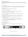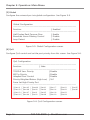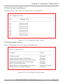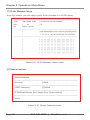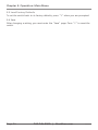
1
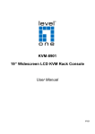
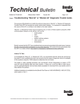
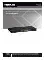
LB9316A LB9316C-SC-2K LB9316C-SC-20K LB9324A Value Managed Switches Provides serial management in a value-priced, BLACK BOX yet capable switch. ® Customer Support Information Order toll-free in the U.S.: Call 877-877-BBOX (outside U.S. call 724-746-5500) FREE technical support 24 hours a day, 7 days a week: Call 724-746-5500 or fax 724-746-0746 • Mailing address: Black Box Corporation, 1000 Park Drive, Lawrence, PA 15055-1018 • Web site: www.blackbox.com • E-mail: [email protected] FCC and IC RFI Statements FEDERAL COMMUNICATIONS COMMISSION AND INDUSTRY CANADA RADIO FREQUENCY INTERFERENCE STATEMENTS This equipment generates, uses, and can radiate radio-frequency energy, and if not installed and used properly, that is, in strict accordance with the manufacturer’s instructions, may cause interference to radio communication. It has been tested and found to comply with the limits for a Class A computing device in accordance with the specifications in Subpart B of Part 15 of FCC rules, which are designed to provide reasonable protection against such interference when the equipment is operated in a commercial environment. Operation of this equipment in a residential area is likely to cause interference, in which case the user at his own expense will be required to take whatever measures may be necessary to correct the interference. Changes or modifications not expressly approved by the party responsible for compliance could void the user’s authority to operate the equipment. This digital apparatus does not exceed the Class A limits for radio noise emission from digital apparatus set out in the Radio Interference Regulation of Industry Canada. Le présent appareil numérique n’émet pas de bruits radioélectriques dépassant les limites applicables aux appareils numériques de la classe A prescrites dans le Règlement sur le brouillage radioélectrique publié par Industrie Canada. Normas Oficiales Mexicanas (NOM) Electrical Safety Statement INSTRUCCIONES DE SEGURIDAD 1. Todas las instrucciones de seguridad y operación deberán ser leídas antes de que el aparato eléctrico sea operado. 2. Las instrucciones de seguridad y operación deberán ser guardadas para referencia futura. 3. Todas las advertencias en el aparato eléctrico y en sus instrucciones de operación deben ser respetadas. Page 2 724-746-5500 | blackbox.com LB9316A NOM Statement 4. Todas las instrucciones de operación y uso deben ser seguidas. 5. El aparato eléctrico no deberá ser usado cerca del agua—por ejemplo, cerca de la tina de baño, lavabo, sótano mojado o cerca de una alberca, etc. 6. El aparato eléctrico debe ser usado únicamente con carritos o pedestales que sean recomendados por el fabricante. 7. El aparato eléctrico debe ser montado a la pared o al techo sólo como sea recomendado por el fabricante. 8. Servicio—El usuario no debe intentar dar servicio al equipo eléctrico más allá lo descrito en las instrucciones de operación. Todo otro servicio deberá ser referido a personal de servicio calificado. 9. El aparato eléctrico debe ser situado de tal manera que su posición no interfiera su uso. La colocación del aparato eléctrico sobre una cama, sofá, alfombra o superficie similar puede bloquea la ventilación, no se debe colocar en libreros o gabinetes que impidan el flujo de aire por los orificios de ventilación. 10. El equipo eléctrico deber ser situado fuera del alcance de fuentes de calor como radiadores, registros de calor, estufas u otros aparatos (incluyendo amplificadores) que producen calor. 11. El aparato eléctrico deberá ser connectado a una fuente de poder sólo del tipo descrito en el instructivo de operación, o como se indique en el aparato. 12. Precaución debe ser tomada de tal manera que la tierra fisica y la polarización del equipo no sea eliminada. 13. Los cables de la fuente de poder deben ser guiados de tal manera que no sean pisados ni pellizcados por objetos colocados sobre o contra ellos, poniendo particular atención a los contactos y receptáculos donde salen del aparato. 14. El equipo eléctrico debe ser limpiado únicamente de acuerdo a las recomendaciones del fabricante. 15. En caso de existir, una antena externa deberá ser localizada lejos de las lineas de energia. LB9316A 724-746-5500 | blackbox.com Page 3 NOM Statement 16. El cable de corriente deberá ser desconectado del cuando el equipo no sea usado por un largo periodo de tiempo. 17. Cuidado debe ser tomado de tal manera que objectos liquidos no sean derramados sobre la cubierta u orificios de ventilación. 18. Servicio por personal calificado deberá ser provisto cuando: A: El cable de poder o el contacto ha sido dañado; u B: Objectos han caído o líquido ha sido derramado dentro del aparato; o C: El aparato ha sido expuesto a la lluvia; o D: El aparato parece no operar normalmente o muestra un cambio en su desempeño; o E: El aparato ha sido tirado o su cubierta ha sido dañada. Page 4 724-746-5500 | blackbox.com LB9316A Trademarks Used in this Manual Trademarks Used in this Manual Black Box and the Double Diamond logo are registered trademarks of BB Technologies, Inc. Hyperterminal is a registered trademark of of Hilgraeve, Inc. Any other trademarks mentioned in this manual are acknowledged to be the property of the trademark owners. LB9316A 724-746-5500 | blackbox.com Page 5 Table of Contents Table of Contents Chapter 1. Page Specifications ......................................................................................... 7 2. Overview ......................................................................................... 8 2.1Introduction.................................................................................... 8 2.2Features ......................................................................................... 8 2.3 What’s Included.............................................................................. 8 2.4 Hardware Description..................................................................... 8 2.4.1 Front Panel....................................................................... 8 2.4.2 Back Panel........................................................................ 9 3. Hardware Installation............................................................................... 10 4. Software Configuration............................................................................11 5. Operation: Main Menu............................................................................ 14 5.1Status ....................................................................................... 14 5.2Configuration............................................................................... 14 5.3Security ....................................................................................... 19 5.4Diagnostics................................................................................... 19 5.5 Load Factory Defaults................................................................... 20 5.6Save ....................................................................................... 20 Page 6 724-746-5500 | blackbox.com LB9316A Chapter 1: Specifications 1. Specifications Buffer: LB9316A: 1.625 MB; LB9324A: 1.25 MB Temperature Tolerance: Operating: 32 to 131° F (0 to 55° C) Humidity Tolerance: Operating: 10 to 90%, noncondensing Filtering and Forwarding Rate: 10 Mbps: 14,880 pps; 100 Mbps: 148,800 pps MAC Addresses: LB9316A: 4K; LB9324A: 8 K Standards: IEEE 802.3 10BASE-T, IEEE 802.3u 100BASE-T, IEEE 802.3x flow control Switching Method: Store-and-forward CE Approval: Yes RoHS: Yes Connectors: LB9316A: (16) RJ-45, (1) Power; LB9324A: (24) RJ-45, (1) Power Indicators: LB9316A: (17) LEDs: (1) Power, (16) LINK/ACT; LB9324A: (25) LEDs: (1) Power, (24) LINK/ACT Power: Both models: 100–240 VAC, 50–60 Hz internal power supply; LB9316A: 7.5 watts maximum; LB9324A: 10 watts maximum Size: 1.75" (1U) x 17.3" x 8.7"D (4.4 x 44 x 22 cm) LB9316A 724-746-5500 | blackbox.com Page 7 Chapter 2: Overview 2. Overview 2.1 Introduction Use this basic utility switch to connect up to 16 or 24 10-/100-Mbps Ethernet devices. Manage the devices via a PC connected to the switch‘s console port. 2.2 Features • Supports real-time status read/write operation • Provides on-line link status • Supports Auto MDI/MDI-X, so you don’t need crossover cables • Supports trunk speeds up to 800 Mbps • Includes optional fiber optic module slot for 100BASE-FX applications 2.3 What’s Included Your package should contain the following items. If anything is missing or damaged, contact Black Box Technical Support at 724-746-5500 or [email protected]. • (1) Value Managed Switch with DB9 connector on front panel • (2) Optional Fiber Modules (multimode: part number LB9316C-SC-2K, single-mode: part number LB9316C-SC-20K) • This user’s manual 2.4 Hardware Description 2.4.1 Front Panel Figure 2-1 shows the front panel of the switch. Table 2-1 describes its components. 1 2 3 4 5 Figure 2-1. Front panel. Page 8 724-746-5500 | blackbox.com LB9316A Chapter 2: Overview Table 2-1. Front panel components. NumberComponent Description 1 DB9 connector Console port connects to PC for management. 2 Power LED Lights when power to the unit is on. 3 LINK/ACT LEDs (16) on the LB9316A; (24) on the LB9324A; indicates port activity 4 RJ-45 connectors (16) on the LB9316A; (24) on the LB9324A; links to 10-/100-Mbps Ethernet devices 5 Optional module (1) 100BASE-FX module slot(multimode: part number LB9316C-SC-2K, single-mode: part number LB9316C-SC-20K) 2.4.2 Back Panel Figure 2-2 shows the back panel of the switch. Table 2-2 describes its components. 6 7 Figure 2-2. Back panel. Table 2-2. Back panel components. NumberComponent Description 6 Switch Press ON to power on the switch; Press OFF to power off the switch 7 Accepts 100–240 VAC, 50–60 Hz power plug LB9316A Power receptacle 724-746-5500 | blackbox.com Page 9 Chapter 3: Hardware Installation 3. Hardware Installation 1. Make sure your PC and the Value Managed Switch are powered off. 2. Connect the cable from the PC serial port to the DB9 connector on the switch. See Figure 3-1. Value Managed Switch PC console Figure 3-1. Attaching a PC to the switch’s console port. NOTE: When you connect the cable from the PC serial port, remember which serial port you connected. Page 10 724-746-5500 | blackbox.com LB9316A Chapter 4: Software Configuration 4. Software Configuration Follow these steps to install the software: Step 1: Go to Start > Programs > Accessories > Communications > HyperTerminal. See Figure 4-1. Figure 4-1. HyperTerminal screen. Step 2: Enter a name for a new connection, and then press “OK.” See Figure 4-2. Figure 4-2. New Connection screen. LB9316A 724-746-5500 | blackbox.com Page 11 Chapter 4: Software Configuration Step 3: Choose the serial port that you connected. See Figure 4-3. Figure 4-3. Connect To screen. Step 4: Configure the COM port properties. See Figure 4-4. The default settings are: Bits per second: 19200 Data bits: 8 Parity: None Stop bits: 1 Flow control: None Figure 4-4. COM1 Properties screen. Page 12 724-746-5500 | blackbox.com LB9316A Chapter 4: Software Configuration Step 5: Press any key to enter the login screen. Initializing…initialization done. Press any key into login screen. Figure 4-5. Press key to enter login screen. LB9316A 724-746-5500 | blackbox.com Page 13 Chapter 5: Operation: Main Menu 5. Operation: Main Menu Main Menu [1] Status [2] Configuration [3] Security [4] Diagnostics [5] Load Factory Defaults [6] Save Figure 5-1. Main menu. 5.1 Status Press [1] from the Main Menu (see Figure 5-1) to select enabled status, link, speed duplex, TX bandwidth control, and flow control for each port. 5.2 Configuration Press [2] from the Main Menu, and the Configuration Menu appears (see Figure 5-2). Configuration Menu [1] Port [2] Trunking [3] Global [4] QoS [5] Priotrity Tag Insert/Remove [6] VLAN Global Control [7] VLAN Member Setup [8] Device Features Figure 5-2. Configuration Menu. Page 14 724-746-5500 | blackbox.com LB9316A Chapter 5: Operation: Main Menu [1] Port To set port status, press the “Enter” key on the keyboard. See Figure 5-3. Config Port ------------------------------------------------------------------------------ Port | Enabled | Speed |Flow Control Bandwidth | advertisement RX TX 01 Enable 100 M Full Enable Non-control Non-control 02 Enable 100 M Full Enable Non-control Non-control 03 Enable 100 M Full Enable Non-control Non-control 04 Enable 100 M Full Enable Non-control Non-control 05 Enable 100 M Full Enable Non-control Non-control 06 Enable 100 M Full Enable Non-control Non-control 07 Enable 100 M Full Enable Non-control Non-control 08 Enable 100 M Full Enable Non-control Non-control Figure 5-3. Config Port screen. [2] Trunking Press the “Enter” key on the keyboard to select trunking. See Figure 5-4. Enable Trunking ------------------------------------------------------------------------------ Trunking | Enabled --------------------------------------------------------------------------------- Trunk1 (port 1, 2) | Disable Trunk2 (port 3, 4) | Disable Trunk3 (port 5, 6, 7, 8) | Disable Trunk4 (port 9, 10 ,11, 12) | Disable Trunk5 (port 13, 14, 15, 16) | Disable Trunk6 (port 17, 18 ,19, 20) | Disable Trunk7 (port 21, 22, 23, 24) | Disable Trunk8 (port 25, 26) | Disable Figure 5-4. Trunking screen. LB9316A 724-746-5500 | blackbox.com Page 15 Chapter 5: Operation: Main Menu [3] Global Configure the universal port via global configuration. See Figure 5-5. Global Configuration ------------------------------------------------------------------------------ Function | Enabled ------------------------------------------------------------------------------ Half Duplex Back Pressure Flow | Enable Broadcast Storm Filtering Control | Disable Loop Detect | Disable Figure 5-5. Global Configuration screen. [4] QoS Configure QoS control and set the port priority from this screen. See Figure 5-6. QoS Configuration ------------------------------------------------------------------------------ Function | State ------------------------------------------------------------------------------- TOS/Diff Serv. Priority | Disable 802.1p Priority | Disable Adapted Flow Control | Disable Priority Weighted Ration (High:Low) | 16:1 Force Set High-Priority Port ------------------------------------------------------------------------------- [ ]Port 01 [ ]Port 05 [ ]Port09 [ ]Port13 [ ]Port 17 [ ]Port21 [ ]Port25 [ ]Port 02 [ ]Port 06 [ ]Port10 [ ]Port14 [ ]Port 18 [ ]Port22 [ ]Port 03 [ ]Port 07 [ ]Port11 [ ]Port15 [ ]Port 19 [ ]Port23 [ ]Port 04 [ ]Port 08 [ ]Port12 [ ]Port16 [ ]Port 20 [ ]Port24 [ ]Port26 Figure 5-6. QoS Configuration screen. Page 16 724-746-5500 | blackbox.com LB9316A Chapter 5: Operation: Main Menu [5] Priority Tag Insert/Remove Configure ports’ tag status from this screen. See Figure 5-7. Port Tagging Control ------------------------------------------------------------------------------ Port | Tagging State ------------------------------------------------------------------------------ 01 | Don’t touch 02 | Don’t touch 03 | Don’t touch 04 | Don’t touch 05 | Don’t touch 06 | Don’t touch 07 | Don’t touch 08 | Don’t touch Figure 5-7. Port Tagging Control screen. [6] VLAN Global Control Select VLAN status from this page. See Figure 5-8. Global Configuration ------------------------------------------------------------------------------ Function | State ------------------------------------------------------------------------------ VLAN Function | Disable Unicast Packet Inter-VLAN Leaky | Disable ARP broadcast Packet Inter-VLAN Leaky | Disable IP Multicast Packet Inter-VLAN Leaky | Disable 802.1Q VLAN tag aware | Disable Ingress Rule for Acceptable frame types | Admit all Frames Ingress Rule for Ingress Filtering | Disable Figure 5-8. VLAN Global Control screen. LB9316A 724-746-5500 | blackbox.com Page 17 Chapter 5: Operation: Main Menu [7] VLAN Member Setup From this screen, you can select ports to be included in a VLAN group. | Port Based VLAN | VLAN | Port [VLAN member] Entry VLAN | | ID No. | 802.1q VLAN or ------------------------------------------------------------------------------------------------||0|0|0|0|0|0|0|0|0|1|1|1|1|1|1|1|1|1|2|2|2|2|2|2|2|2|2 1 2 3 4 5 6 7 8 9 0123456789 0123456789 ------------------------------------------------------------------------------------------------ | | | | | | | | | | | | | | || | || | | | | | | | | | | | | | | | | | | | | | || | || | | | | | | | | | | | | | | | | | | | | | || | || | | | | | | | | | | | | | | | | | | | | | || | || | | | | | | | | | | | | | | | | | | | | | || | || | | | | | | | | | | | | | | | | | | | | | || | || | | | | | | | Figure 5-9. VLAN Member Setup screen. [8] Device Features Device Features ------------------------------------------------------------------------------ Function | State ------------------------------------------------------------------------------ IGMP Snooping | Disable ------------------------------------------------------------------------------ IP Multicast Router Port (Read Only) (Auto-refresh) ------------------------------------------------------------------------------None. Figure 5-10. Device Features screen. Page 18 724-746-5500 | blackbox.com LB9316A Chapter 5: Operation: Main Menu 5.3 Security An authentication key prevents the connected PCs from accessing the console configuration. Figure 5-11 shows the Security screen. Security ------------------------------------------------------------------------------ Function | Value ------------------------------------------------------------------------------- Management Authorized Port Control ------------------------------------------------------------------------------- [V]Port 01 [V]Port 05 [V]Port09 [V]Port13 [V]Port 17 [V]Port21 [V]Port25 [V]Port 02 [V]Port 06 [V]Port10 [V]Port14 [V]Port 18 [V]Port22 [V]Port 03 [V]Port 07 [V]Port11 [V]Port15 [V]Port 19 [V]Port23 [V]Port 04[V]Port 08 [V]Port12 [V]Port16 [V]Port 20 [V]Port24 [V]Port26 Figure 5-11. Security screen. 5.4 Diagnostics Figure 5-12 shows the Diagnostics screen. Diagnositics (Read Only) (Auto-refresh) ------------------------------------------------------------------------------ Fault Information | VLAN ID | Port (VLAN member) ------------------------------------------------------------------------------- Trunk Link Warning | Trunk1(P01,02 )=>[ ] Trunk5(P13,14,15,16)=>[ ] | Trunk2 (P03,04 )=>[ ] Trunk6(P13,14,15,16)=>[ ] | Trunk 3 (P05,06,07,08)=>[ ] Trunk7(P13,14,15,16)=>[ ] | Trunk 4 (P09,10,11,12 )=>[ ] Trunk8(P13,14,15,16)=>[ ] ------------------------------------------------------------------------------- Network Loop Fault | P01 P02 P03 P04 P05 P06 P07 P08 P09 P10 P11 P12 P13 Port Detected | [ ] [ ][ ] [ ][ ] [ ][ ] [ ][ ] [ ][ ] [ ][ ] [ ] ------------------------------------------------------------------------------- | P14 P15 P16 P17 P18 P19 P20 P21 P22 P23 P24 P25 P26 | [ ] [ ][ ] [ ][ ] [ ][ ] [ ][ ] [ ][ ] [ ][ ] [ ] ------------------------------------------------------------------------------- Note: [X]=>1. Detected some port link down that belonged to the trunk group. =>2. Some port loop detected. Figure 5-12. Diagnostics screen. LB9316A 724-746-5500 | blackbox.com Page 19 Chapter 5: Operation: Main Menu 5.5 Load Factory Defaults To set the switch back to its factory defaults, press “Y” when you are prompted. 5.6 Save After changing a setting, you must enter the “Save” page. Press “Y” to reset the switch. Page 20 724-746-5500 | blackbox.com LB9316A NOTES LB9316A 724-746-5500 | blackbox.com Page 21 NOTES Page 22 724-746-5500 | blackbox.com LB9316A NOTES LB9316A 724-746-5500 | blackbox.com Page 23 Black Box Tech Support: FREE! Live. 24/7. Tech support the way it should be. Great tech support is just 60 seconds away at 724-746-5500 or blackbox.com. About Black Box Black Box Network Services is your source for more than 118,000 networking and infrastructure products. You’ll find everything from cabinets and racks and power and surge protection products to media converters and Ethernet switches all supported by free, live 24/7 Tech support available in 60 seconds or less. © Copyright 2014. Black Box Corporation. All rights reserved. LB9316A, rev. 2 724-746-5500 | blackbox.com