1
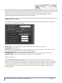
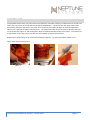
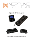
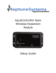
Apex AquaController Dosing and Fluid Metering System (DŌS) Setup Guide Table of Contents DOSING AND FLUID METERING SYSTEM – INTRODUCTION ............................................ 1 FEATURES ...................................................................................................................... 1 INSTALLATION ............................................................................................................... 1 PACKAGE CONTENTS .......................................................................................................... 1 Initial Connections.............................................................................................................. 2 Startup ............................................................................................................................. 2 VERIFY THE INSTALLATION ........................................................................................... 2 PREPARING YOUR TUBING FOR DŌS .............................................................................. 2 CALIBRATING DŌS ......................................................................................................... 3 PROGRAMMING EXAMPLES (APEX FUSION INTERFACE)................................................. 3 PROGRAMMING EXAMPLES (CLASSIC WEB INTERFACE) ................................................ 4 NEW PROFILE TYPE ............................................................................................................ 4 TESTING YOUR PUMP AND PROFILE ...................................................................................... 5 SIMPLE 2-PUMP DAY/NIGHT DOSING EXAMPLE ...................................................................... 5 DOSING CALCIUM AND ALKALINITY ..................................................................................... 6 AUTOMATIC WATER CHANGE ............................................................................................... 7 MAINTENANCE ............................................................................................................... 9 NEPTUNE SYSTEMS LIMITED WARRANTY ..................................................................... 10 CE DECLARATION OF CONFORMITY .............................................................................. 11 DOSING AND FLUID METERING SYSTEM – INTRODUCTION Congratulations on your purchase of this Apex AquaController expansion accessory. The DŌS is an easy to use fluid delivery system that connects seamlessly with your Apex system for ease of use and flexibility. Because DŌS is part of your overall Apex system, you can integrate its functions into its other monitoring and control functions. FEATURES 2-part dosing (Calcium and Alkalinity) Other additives dosing Automatic water changes Micro-quantity dosing Delivery of liquid foods and supplements Compatible with all Apex Systems INSTALLATION WARNING: Your Apex Base Unit must be running firmware version 4.33_BD14 or higher to support the DŌS. The current firmware version can be checked from the Apex Display on the Self Test screen. If needed, please upgrade the Apex Base Unit firmware before proceeding with the installation. See the Apex Setup and Programming Guide for firmware upgrade instructions. The DŌS can be placed on a tabletop or hung securely in a location free from moisture. Use #8 or #10 wood screws spaced 6 ½” apart if hanging. The DŌS keyhole slots can be accessed through the knockout mounting tabs on the back of its case. If mounting on drywall, use drywall anchors (mounting hardware not included). Mount all modules above the water line of the aquarium. Be sure to utilize drip loops on all power cords, AquaBus cables and probe cables. WARNING: Water damage to the module will void your warranty! Mount all modules in locations safe from moisture exposure. PACKAGE CONTENTS The DŌS comes with 5 items in the box from Neptune Systems: 1. The DŌS module 2. 24vdc power supply 3. 6’ Aquabus cable 4. 50 mL graduated cylinder 5. 4 meters of tubing, 6mm OD, 4mm ID, 1mm wall thickness If you’re missing any of these items, please contact Neptune Systems Support (see last page for contact information). Dosing and Fluid Metering System – Setup Guide Page 1 INITIAL CONNECTIONS Plug one end of the included AquaBus cable into either of the AquaBus ports on the DŌS and the other end into an available AquaBus port anywhere on your existing Apex system. It makes no difference which AquaBus port is used and you do not need to power down the system when connecting AquaBus accessories as the system is plug-and-play. Then connect the power supply. There is no need to use an energy bar outlet – a wall outlet will suffice if available. WARNING: NEVER plug standard USB devices into any AquaBus connector or AquaBus accessories into computer USB ports. Damage to the AquaBus accessory and/or USB device may result. STARTUP Once you ensure you have the proper software version you can connect the DŌS to your system. As soon as the DŌS is connected to an active AquaBus, the module will power up and begin to initialize. When first connected to an Apex Base Unit (through the AquaBus), the DŌS will automatically be assigned an AquaBus address and be added to the Apex configuration. The LED Status indicator on the DŌS will flash green while it is being initialized. This takes a few seconds. Once initialized, the LED Status indicator will be solid orange. The LED Status indicator will flash orange if communication with the Apex Base Unit is lost. Solid Orange Flashing Orange Solid Blue Flashing Red Flashing Green Ready Fallback Mode Pump(s) running Over temp/Hardware issue Initializing LED Status Indicator VERIFY THE INSTALLATION Verify the DŌS was initialized and added to the Apex configuration: Apex Display: Setup – Module Setup – Modify Name – from this screen, you can see all AquaBus modules installed on the system. Classic Apex Web Interface: Configuration – Module Setup – Verify the DŌS is listed in the Apex Module List and note the module number assigned to it. There will be two programmable outlets automatically created when you connect the DŌS to your Apex system. They will be called DOS_X_1 and DOS_X_2 where ‘X’ is the module number assigned to your DŌS. It is these outlets that will be programmed. If you don’t see these outlets after connection your DŌS, verify you have the proper firmware and that you have a solid orange status light for each of the pumps. PREPARING YOUR TUBING FOR DŌS After making your initial connections and verifying the installation, you’ll want to physically mount or position DŌS in its permanent location. After doing so you’ll want to measure your tubing for DŌS and cut it to the appropriate length. Dosing and Fluid Metering System – Setup Guide Page 2 On your DŌS pump cover and peristaltic assembly there is an “In” and and “Out” label. While the pump can run forward or reverse, typically it will run “in” to “out.” So “in” will be liquid coming from a container and “out” will be going to your aquarium. After measuring and cutting your tubing, remove the compression fittings from your pump cover and connect the tubing. Finally after connecting the tubing secure it to the assembly by locking the compression fittings back on your pump assembly CALIBRATING DŌS Your DŌS pumps must be calibrated before using or it WILL NOT dispense an accurate amount of fluid. THIS STEP IS IMPORTANT. The calibration is a simple process that is performed one pump at a time. You can calibrate using the Display module or the classic Apex web pages. Calibration is the process of running a pump for a fixed amount of time and confirming how much fluid it pumps using the graduated cylinder (included). Put the in/suction tube into a glass of tap water. Put the out/discharge tube into an empty glass. Prime the pump by pressing the button on the front of the DŌS that corresponds to the left or right pump and hold it until all air bubbles are out of the tubing. Now put the discharge tube into the graduated cylinder and you can begin the calibration. From the Display module, navigate to Setup – Module Setup – Config Module or via the web pages navigate to Configuration – Module Setup. Select your DŌS module. Then select the pump you want to calibrate. Pump #1 is the left side pump, #2 is the right side pump. Then press ‘OK’. The pump will run for approximately 90 seconds then stop. After it stops, note how much water (mL) is in the graduated cylinder and enter that value. There will be about 40 mL of liquid, maybe a little more or less but it’s that exact amount that becomes your calibration. When viewing the graduated cylinder it’s important to view it directly level with the liquid level – don’t view at an angle. Also, you will note that the liquid in the cylinder curves upward at the walls of the cylinder. The bottom is called the “meniscus”. Your reading must be from the meniscus. Precision is important here if you want accurate dosing so take some time and repeat the calibration if necessary. Repeat the process for the remaining pump. Your DŌS is now calibrated. Any time you change the types of fluid you’re pumping, change your tubing orientation or replace your pump tubing you should recalibrate. PROGRAMMING EXAMPLES (APEX FUSION INTERFACE) For assistance with configuring your DŌS with Apex Fusion, please refer to the “DŌS Get Started Guide.” In the Guide you can see two common applications of DŌS; Dosing Additives and Continuous Water Change. http://neptunesystems.com/getstarted/dos Dosing and Fluid Metering System – Setup Guide Page 3 PROGRAMMING EXAMPLES (CLASSIC WEB INTERFACE) Refer to the Apex Setup and Programming Guide or the Comprehensive Reference Manual for detailed instructions on how to configure and program profiles and outlets. These examples assume a basic understanding of profiles and outlets and use the Classic Interface. NEW PROFILE TYPE The DŌS has a new type of a profile (for more on profiles, please see the Comprehensive Reference Manual) that you can use to configure your pump. Profile Name – Any unique name you chose, 8 characters or less, no special characters Control Type – Select ‘Dose’ Dose Rate – Select the appropriate rate for your application. Note you can select 7, 12, 25, 60, 125 or 250 mL/min in either forward (in to out) or reverse (out to in) direction. Per Dose Amount (mL) – enter the dose in mL that you want. Dose Interval (s) – What is the interval between the end of this dose and the end of the next dose? Number of Doses – How many doses (dose + interval) per run of this profile? Common profile errors: ‘Too much dosing in too short a period’ – this error occurs when the Dose Interval is too short. It is designed to prevent the pumps from overheating. The Dose Interval should be at least 3x the time it takes to deliver 1 dose. For example, if the Dose Rate is 12 mL/min and the Per Dose Amount is 3 mL, it should take 15 seconds to deliver that 3 mL dose. Therefore, the minimum Dose Interval should be > 45 seconds (3 x 15). The interval will be your dose (15 sec) plus a 30 seconds (2 x 15) pause plus at least 1 second. See the following diagram: Dosing and Fluid Metering System – Setup Guide Page 4 DOSE INTERVAL DOSE #1 PAUSE DOSE #2 ‘Too much dosing in a given dose’ – this error occurs when the Per Dose Amount is more than 8x the Dose Rate and as above, is designed to keep the pumps from overheating. For example, with a Dose Rate of 60 mL/min, your Per Dose Amount should be <= 480 mL (8 x 60). TESTING YOUR PUMP AND PROFILE A simple profile and program will enable you to test your pump and give you an understanding of the logic behind both. Using the web pages, modify a spare profile and enter the following data: Profile Name – ‘dostst’ Control Type – Select ‘Dose’ Dose Rate – 60 mL Per Dose Amount (mL) – 5 Dose Interval (s) – 31 Number of Doses – 2 In your dosing outlet (default name is DOS_X_Y, X is the Aquabus ID of the DŌS) enter the following program in ‘Advanced’ mode: Set OFF If FeedA 000 Then dostst (if you’re already using FeedA, just select an unused Feed mode) To activate, select FeedA from either your Dashboard, the Display or your smartphone. Cancel the Feed mode if something doesn’t seem correct. This will deliver a sample dose of 5 mL over 10 seconds, pause for approximately 20 seconds then deliver another 5 mL dose, then stop. From here you can experiment with the times and dosing rates, testing each change simply by activating the appropriate feed mode. SIMPLE 2-PUMP DAY/NIGHT DOSING EXAMPLE Using what you learned during the test above, you can now configure a dosing profile and incorporate that into a dosing program. In this example, we will dose 5 mL every hour during the night from pump #1 and 5 mL every hour during the day from pump #2. Dosing and Fluid Metering System – Setup Guide Page 5 Profile setup: Profile Name Control Type Dose Rate Per Dose Amount Dose Interval Number of Doses Profile #1 Nite_dos Dose 60 5 3600 24 Profile #2 Day_dos Dose 60 5 3600 24 Program: DOS_1 Set OFF If Time 18:00 to 06:59 then Nite_dos DOS_2 Set OFF If Time 07:00 to 17:59 then Day_dos You can add in additional rules to stop dosing if certain probe parameters are met. For example, if you’re dosing Kalk and you want to only dose at night but stop if the pH rose above 8.4, you could use: Set OFF If Time 18:00 to 06:59 then Nite_dos If pH > 8.40 then OFF DOSING CALCIUM AND ALKALINITY In this example, we need to dose Calcium and Alkalinity 30 minutes apart to avoid precipitation. If the pH rises above 8.40 we want to suspend dosing. Dosing will happen every hour but only at night. Profile Name Control Type Dose Rate Per Dose Amount Dose Interval Number of Doses Calcium Ca Dose 7 1.1 3600 12 Dosing and Fluid Metering System – Setup Guide Alkalinity Alk Dose 7 2 3600 12 Page 6 Program DOS_Ca DOS_Alk Set OFF If Time 18:00 to 06:00 then Ca If pH > 8.40 Then OFF Set OFF If Time 18:30 to 06:30 Then Alk If pH > 8.40 Then OFF AUTOMATIC WATER CHANGE In this example, the DOS will be used to exchange old saltwater for new saltwater. Because of the precision of the DOS Dosing and Fluid Metering System we can accomplish this without the need for floats or elaborate program controls. The pumps will move a precise amount of saltwater each and every time. The exchange will be 4 x 1,000 mL or just a little over 2 gallon of water each day and will take place over a 96 minute period. The exchange will run M – F for a total of approximately 10.5g per week. On a 100g tank, that would be 10% / week. Profile Name Control Type Dose Rate Per Dose Amount Dose Interval Number of Doses Old Saltwater OSW Dose 250 1000 1500 4 New Saltwater NSW Dose 250 1000 1500 4 Program DOS_OSW Set OFF If Time 12:00 to 14:00 Then OSW If DOW S-----S Then OFF DOS_NSW Set OFF If Time 12:08 to 14:08 Then NSW If DOW S-----S Then OFF The first program will begin at 12:00 and pump out old saltwater. Each ‘dose’ will take 4 minutes (1000 / 250) and will pump out 1000 mL. The second program for the NSW will wait 8 minutes then start the exact same cycle and pump 1000 mL of NSW back into the tank. Meanwhile the OSW pump is waiting to cool down for 16 minutes after which time it will repeat the cycle. Same for the NSW pump. This will repeat another 2 times and 4000 mL of water (2.1 gallons) will have been exchanged. Dosing and Fluid Metering System – Setup Guide Page 7 If you wanted to extend this simply change the per dose amount, dose interval and number of doses. Simply changing the dose rate to 250 mL/min and dose amount to 2000 would exchange 2 gallons in the same time period. Dosing and Fluid Metering System – Setup Guide Page 8 MAINTENANCE The peristaltic pump tubes (the ones inside the pump itself) eventually need to be replaced due to normal wear. This is the only part on the pump that should require maintenance. The pump rotor and pump tube can be accessed by squeezing the sides of the pump cover (Figure 1) and pulling straight out from the DŌS being careful not to damage the plastic tabs (Figure 2). The pump tube itself can be removed by carefully lifting up on the nozzle tips (Figure 3) and working the tubing from behind and around the pinch rollers. The nozzles are a tight friction fit into the pump cover but will come straight up with a little pressure. Replacement pump tubing can be ordered from Neptune Systems. For more information please go to: http://www.neptunesystems.com Figure 1 Figure 2 Dosing and Fluid Metering System – Setup Guide Figure 3 Page 9 NEPTUNE SYSTEMS LIMITED WARRANTY Neptune Systems warrants this product to be free from defects in material and workmanship for a period of 1 year from the date of purchase. Probes carry a 90-day warranty. If repair or adjustment is necessary and has not been the result of abuse, misuse, or accidental damage, within the 1-year period, please return the product with proof of purchase, and correction of the defect will be made without charge. For your protection, items being returned must be carefully packed to prevent damage in shipment and insured against possible damage or loss. Neptune Systems will not be responsible for damage resulting from careless or insufficient packaging. Before returning please obtain a return authorization (RMA) number from Neptune Systems at (408) 779-4090. Returned merchandise will not be accepted without a RMA number. Except for the warranty set forth above, Neptune Systems is not responsible for any damages including, but not limited to, consequential damage occurring out of or in connection with the delivery, use or performance of Neptune Systems’ products. Buyer’s remedies for breach of warranty shall be limited to repair, or replacement and full or partial adjustment to purchase price. Information in this manual is subject to change without notice. Please see www.neptunesys.com for the latest product information and product updates. 105 Cochrane Circle, Suite L Morgan Hill, CA 95037 http://www.neptunesystems.com [email protected] Phone 408-779-4090 Fax 408-762-2042 ©2014 Neptune Systems - All Rights Reserved DŌSManual V1 Dosing and Fluid Metering System – Setup Guide Page 10 CE DECLARATION OF CONFORMITY Manufacturer: Neptune Systems, LLC. 105 Cochrane Circle Suite L, Morgan Hill, CA 95037; 408-779-4090 Product: DŌS Dosing and Fluid Metering System Model No. DŌS The undersigned hereby declares, on behalf of the Neptune Systems, LLC. of Morgan Hill, California that the above-referenced product, to which this declaration relates, is in conformity with the provisions of: EN 60950-1+A1:2009 EN 60335-1:2010 The Technical Construction File required by this Directive is maintained at the corporate headquarters of Neptune Systems, LLC, 105 Cochrane Circle, Suite L, Morgan Hill, California. ________________________ Curt Pansegrau President The symbol to the right means that according to local laws and regulations your product should be disposed of separately from household waste. When this product reaches its end of life, take it to a collection point designated by local authorities. Some collection points accept products for free. The separate collection and recycling of your product at the time of disposal will help conserve natural resources and ensure that it is recycled in a manner that protects human health and the environment. Dosing and Fluid Metering System – Setup Guide Page 11