1
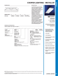
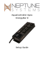
AquaController Apex EnergyBar 8 Setup Guide WELCOME TO AQUACONTOLLER APEX Congratulations on your purchase of the AquaController Apex EnergyBar 8! The EnergyBar 8 allows the AquaController Apex system to control up to eight 120 volt items such as lights, pumps, fans, heaters, chillers and more. PHYSICAL INSTALLATION The EnergyBar 8 should be securely mounted in a location free from moisture. Use wood screws through the mounting tabs or if mounting on drywall, use drywall anchors (mounting screws and anchors not included). • Mount the EnergyBar 8 above the water line of the aquarium. • Be sure to utilize drip loops on all power cords and AquaBus cables plugged in to the EnergyBar 8. • Plug the EnergyBar 8 into a circuit protected by a Ground Fault Circuit Interrupter (GFCI). WARNING: Water damage will void your warranty! Mount the EnergyBar in a location safe from moisture exposure. AQUABUS CONNECTORS The EnergyBar 8 communicates with and provides power to the AquaController Apex base, Apex Display and Apex accessory modules through the AquaBus connector. The EnergyBar 8 has six connectors to connect AquaBus Accessories. There are no limitations on the order AquaBus accessories can be connected or to which AquaBus ports accessories must be connected. The total length of all AquaBus cables should be limited to 200 feet. Please see the AquaController Apex Installation and Getting Started Guide for more information. WARNING: NEVER plug standard USB devices into any AquaBus connector or AquaBus accessories into computer USB ports. Damage to the AquaBus accessory and/or USB device may result. OUTLETS The EnergyBar 8 provides eight switched 120V outlets. They are numbered 1 through 8 as illustrated on the device. Outlets 1-3 and 5-7 are switched with silent solid state devices and can power items up to 5 amps each. Outlets 4 and 8 are switched with relays and can power items up to 10 amps each. The total current draw for all active outlets must be less than 15 amps. Instantaneous as well as a historical graph of the current draw can be viewed from the AquaController Apex Display or through the AquaController web server. Please see the AquaController Installation and Getting Started Guide for more information on monitoring and programming the EnergyBar 8 outlets. Some extremely small loads (Aqualifter pumps, solenoid, LED moon lights) may not turn off when controlled by the solid state outlets (1-3 and 5-7). To solve this problem, try one of the following solutions: • Use one of the relay outlets (4 or 8) for the device. • Plug in an additional load (i.e. small light bulb or fan) with the item having trouble using an outlet strip. • Use an AquaController Socket Expansion module. • Use an AquaController Direct Connect 4 or Direct Connect 4 Heavy Duty. AquaController Apex EnergyBar 8 - Setup Guide Page 1 ENERGYBAR 8 FEATURES • • • • • • • • • • • • • 8 Independently controllable 120V outlets. Built-in 6 port AquaBus hub so that accessories can be easily added. Communicates with and powers the AquaController Apex Display, base unit and accessories through the AquaBus. Active electrical current monitoring and logging through the AquaController Apex. Fail-safe setting. If communication failure occurs between the AquaController Apex and the EnergyBar 8, each outlet can be configured to revert to a user settable default setting. High reliability direct wired connection to the Apex System through the AquaBus (does not use X10). Completely silent operation on the solid state switched outlets. "Soft-Start" on the solid state switched outlets for reduced pump wear. Two outlets with relay switching for higher power switching. Up to 240 EnergyBar 8 devices can be connected together for up to 1920 switched outlets on a single AquaBus. Built-in circuit breaker protected. 4 Mounting Holes for easy installation. Compact custom aluminum enclosure (10.0" x 3.75" x 1.8"). STATUS INDICATOR The EnergyBar 8 has a single LED status indicator to provide the operational status of the EnergyBar 8. The table below lists the possible states of the indicator along with the indicated status. LED State Off Blinking Yellow Solid Yellow Blinking Green Solid Green Status The EnergyBar 8 is not powered The EnergyBar 8 is in boot loader mode and has not been configured by the AquaController Apex The EnergyBar 8 is in boot loader mode and has been configured by the AquaController Apex The EnergyBar 8 is running but has not received commands from the AquaController Apex. Outlets are in Fallback mode The EnergyBar is running and is receiving commands from the AquaController Apex base module AquaController Apex EnergyBar 8 - Setup Guide Page 2 TECHNICAL SPECIFICATIONS Number of Solid State Switched Outlets Number of Relay Switched outlets Maximum Current Draw per Solid State Outlet Maximum Current Draw per Relay Outlet Maximum Allowed Current Draw (total of all outlets) Number of AquaBus Connectors 6 2 5 Amps 10 Amps 15 Amps 6 NEPTUNE SYSTEMS LIMITED WARRANTY Neptune Systems warrants this product to be free from defects in material and workmanship for a period of 1 year from the date of purchase. Probes carry a 90-day warranty. If repair or adjustment is necessary and has not been the result of abuse, misuse, or accidental damage, within the 1-year period, please return the product with proof of purchase, and correction of the defect will be made without charge. For your protection, items being returned must be carefully packed to prevent damage in shipment and insured against possible damage or loss. Neptune Systems will not be responsible for damage resulting from careless or insufficient packaging. Before returning please obtain a return authorization (RMA) number from Neptune Systems at (408) 578-3022. Returned merchandise will not be accepted without a RMA number. Except for the warranty set forth above, Neptune Systems is not responsible for any damages including, but not limited to, consequential damage occurring out of or in connection with the delivery, use or performance of Neptune Systems’ products. Buyer’s remedies for breach of warranty shall be limited to repair, or replacement and full or partial adjustment to purchase price. ©2010 Neptune Systems - All Rights Reserved 6288 San Ignacio Ave. Unit #B San Jose, CA 95119 http://neptunesys.com Phone 408.578.3022 Fax 408.578.9383 EB8 Manual V2 AquaController Apex EnergyBar 8 - Setup Guide Page 3 CE DECLARATION OF CONFORMITY Manufacturer: Neptune Systems, LLC. 6280 San Ignacio Ave. Suite E, San Jose, CA 95119, USA. 408-578-3022 Product: EnergyBar 8 (EB8) Model No. EB8 The undersigned hereby declares, on behalf of the Neptune Systems, LLC. of San Jose, California that the abovereferenced product, to which this declaration relates, is in conformity with the provisions of: EN 60950-1+A1:2009 EN 60335-1:2010 The Technical Construction File required by this Directive is maintained at the corporate headquarters of Neptune Systems, LLC, 6280 San Ignacio Ave. Suite E, San Jose, California. ________________________ The symbol to the right means that according to local laws and regulations your product should be Curt Pansegrau disposed of separately from household waste. When President this product reaches its end of life, take it to a collection point designated by local authorities. Some collection points accept products for free. The separate collection and recycling of your product at the time of disposal will help conserve natural resources and ensure that it is recycled in a manner that protects human health and the environment. AquaController Apex EnergyBar 8 - Setup Guide Page 4