1
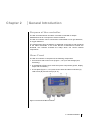
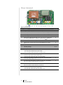
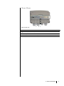
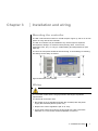
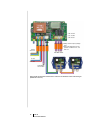
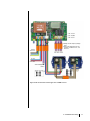
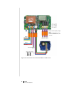
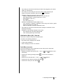
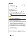
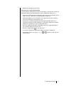
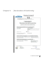
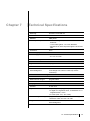
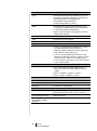
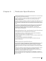
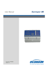
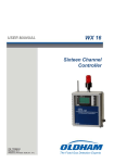
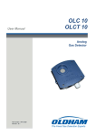
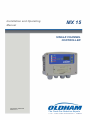
Installation and Operating
Manual
MX 15
SINGLE CHANNEL
CONTROLLER
Part Number: NPM15GB
Revision: B.1
The Fixed Gas Detection Experts
Copyright 2013 by Oldham
All rights reserved. Reproduction in any form, in whole or in part, without the
express written consent of Oldham is strictly prohibited.
The information contained within this manual is true and correct to the best of
our knowledge.
Due to ongoing research and development, the specifications of this product
may be changed at any time without notice.
Oldham
Rue Orfila
Z.I. Est – CS 20417
F – 62027 ARRAS Cedex
Phone: +33 (0)3 21 60 80 80
Fax: +33 (0)3 21 60 80 00
Table of Contents
ii
Table of Contents
Chapter 1
│General Information ................................................... 1
The User’s Guide ......................................................................................... 1
Symbols used .............................................................................................. 1
Safety Warnings .......................................................................................... 2
Important Information .................................................................................. 2
Limitation of liability ..................................................................................... 2
Chapter 2
│Genaral Introduction .................................................. 3
Purpose of the controller ............................................................................. 3
View: Front .................................................................................................. 3
View: Internal ............................................................................................... 4
View: Rear ................................................................................................... 5
Chapter 3
│ Installation and wiring .............................................. 7
Mounting the controller ................................................................................ 7
Wiring .......................................................................................................... 7
Chapter 4
│Operating instructions ............................................. 13
Display indications for start-up................................................................... 13
Channel measurement display .................................................................. 13
Menus ........................................................................................................ 13
Chapter 5
│Cleaning, servicing and maintenance ..................... 19
Cleaning .................................................................................................... 19
Maintenance and servicing ........................................................................ 19
Fuse replacement ...................................................................................... 20
Parts .......................................................................................................... 20
Chapter 6
│Declaration of Conformity........................................ 21
Chapter 7
│Technical Specifications .......................................... 23
Table of Contents
iii
Chapter 8
│ Particular Specifications ......................................... 25
Specifications for mechanical and
electrical installations in Explosive Zones. ................................................. 25
Metrological specifications ......................................................................... 25
Connecting detectors other than
Oldham detectors to the MX 15 controller ................................................. 26
Markings: ................................................................................................... 26
iv
MX 15
Instruction Manual
Chapter 1
│General Information
The User’s Guide
Please read the following notice carefully before installation and start-up,
paying particular attention to the end-user safety instructions. This user’s
guide should be distributed to every individual involved in the start-up, use,
maintenance or repair of the system. The information contained in this
manual, the data and technical drawings are correct as of the date of
publication. Should questions arise, please contact Oldham for additional
information.
This manual is designed to provide users with simple and precise information.
Oldham shall not be held responsible or liable for any misinterpretation that
may result from the reading of this manual. Although every effort is made to
ensure accuracy, this manual may contain unintentional technical
inaccuracies.
On behalf of its clients, Oldham reserves the right to modify the technical
characteristics of its equipment without notice to improve product
performance. This user manual and its contents are the inalienable property of
Oldham.
Symbols used
Icon
Meaning
This symbol indicates useful additional information.
This symbol indicates:
This equipment must be grounded.
This symbol indicates:
Safety grounding terminal. A cable of adequate diameter must
ground any terminal with this signal.
This symbol indicates:
Caution: In the current operating mode, failure to adhere to
the instructions preceding this symbol can result in a risk of
electric shock or death.
This symbol indicates:
Please refer to the instructions.
Double isolation.
1 – General Information
1
European Union (and EEA) only. This icon indicates that in
accordance with Directive DEEE (2002/96/EC) and with the
regulations of your country, this product may not be disposed with
household waste.
Dispose of this product at a collection site intended for electrical
waste, for example an official EEE (Electrical and Electronic
Equipment) collection site with a recycling or take-back program
for authorized products available to consumers whose purchases
replace old EEE products with new equivalents.
Failure to comply with regulations for the disposal of this type of
waste can be harmful to the environment and to public health, as
EEE products typically contain potentially hazardous substances.
Your complete cooperation in the disposal of this product will help
to ensure a more efficient use of natural resources.
Safety Warnings
Icons have been placed on the central controller to call attention to general
use safety precautions. These labels are an integral component of the central
controller. Replace any label that has peeled off or become illegible. The
meanings of these labels are explained below.
Installation and electric connections should be performed by a
qualified professional, according to Oldham's specifications and to
the standards of authorities in the field.
Failure to observe these rules may result in serious injury.
Exactness, particularly regarding electricity and assembly
(couplings, network connections) is imperative.
Important Information
The modification of any component or the use of any third party components
will automatically void any and all guarantees.
The central controller is intended to be used for precise applications of a
technical nature. Exceeding the indicated values is strictly prohibited.
Limitation of liability
Neither Oldham nor any other affiliated organization shall be held liable under
any circumstances for any damage whatsoever including, without limitations,
damages for loss of production, interruption of production, loss of information,
controller failure, personal injury, loss of time, money, or materials, or for any
indirect or consecutive consequence of loss occurring during the use of the
product or the inability to use the product, even in the event that Oldham had
been informed of such damages.
2
MX 15
Instruction Manual
Chapter 2
│Genaral Introduction
Purpose of the controller
The MX 15 measurement and alarm controller is intended for simple
installations that do not require an electrical cabinet.
The MX 15 controller can be connected to combustible or toxic gas detectors,
or oxygen detectors.
The measurement from the detector is displayed on the MX 15 and compared
to the alarm thresholds. In the event that the measurement exceeds the
threshold, the controller activates the relays which can control external
components.
View: Front
The MX 15 controller is composed of the following components:
■
An enclosure with access cover (Figure 1, ref. E) for the settings (zero,
sensitivity);
■
A motherboard (Figure 2) for all of the system components (power, display,
relays and connectors) ;
■
A front plate (Figure 1, ref. D) with sector status and alarm indicators (A),
LCD screen (B) and touch keys (ref. C).
Figure 1: Full view of the MX 15 controller.
2 – General Introduction
3
View: Internal
Figure 2: Internal view.
Ref.
Function
See page
A.
Programming circuit (Explo 340 mA or 4-20 mA).
9
B.
F8 Fuse (5x20, 250 V AC - 630 mA T) with 24V DC power supply.
9
C.
F7 Fuse (5x20, 250 V AC - 100 mA T) with 230 VAC power supply.
8
D.
Secondary ground connection.
E.
Sector power supply terminal (230 V AC or 110 V AC upon request) with
the following identifications: L (phase), N (neutral) and
8
(ground).
F.
Power terminal block 24 V DC (0, + 24V).
8
G.
Terminal block connection with remote acknowledgment (dry contact
8
NO).
H.
Terminal block detector connection.
9
J.
Sensitivity settings.
16, 17
K.
Zero adjustment.
16, 17
L.
Configuration jumper (J17) for Fault relay.
- NC: Fault relay contact closed in alarm mode.
- NO: Fault relay contact open when not in alarm mode.
9
M.
Configuration jumper (J19) for RL1 relay.
9
- NC: RL1 relay contact closed in alarm mode.
- NO: RL1 relay contact open when not in alarm mode.
4
N.
Fault relay terminal block. Contacts CT, 250 V AC – 2A. Contact status
not in alarm mode as defined by J17 (ref. L).
9
P.
RL1 alarm relay terminal block. Contacts CT, 250 V AC – 2A. Contact
status not in alarm mode as defined by J19 (ref. M).
9
Q.
RL2 alarm relay terminal block. Contacts CT, 250 V AC – 2A . Contact
status not in alarm mode as defined by J18 (ref. R).
9
R.
Configuration jumper (J18) for RL2 relay.
- NC: RL2 relay contact closed in alarm mode.
- NO: RL2 relay contact open when not in alarm mode.
9
MX 15
Instruction Manual
View: Rear
Figure 3: Rear view
Ref.
Function
See page
A.
Mounting rail (DIN format)
B.
Fixing the enclosure to the rail
C.
Stop for removal of the enclosure; pull downward to release.
2 – General Introduction
5
6
MX 15
Instruction Manual
Chapter 3
│ Installation and wiring
Mounting the controller
The MX 15 should be mounted on a DIN rail (see Figure 3), with 5 cm of free
space on every side of the controller.
The MX 15 controller may be installed in any area except for explosive
atmospheres, ideally in a monitored area (security office, control room,
equipment room, etc.), in a dry (no condensation) and temperate area (see
page 23).
The unit’s access panel should be forward facing, so that settings, monitoring
and wiring can be easily accessed.
Figure 4: Dimensions of the controller
Wiring
Also refer to the Particular Specifications chapter on page 25.
The controller meets Class II surge protection and Degree 2 pollution
requirements.
The electrical connection must:
■
Be carried out by a specialist and (with the controller) with the power
supply disconnected (electric power cut) ;
■
Respect the current regulations (NF C 15-100) ;
■
Use a power cable connected to the grid (230 VAC) with a minimum
2
diameter of 1.5 mm² and a maximum diameter of 2.5 mm .
3 – Installation and wiring
7
Verify the current and the grid power supply: the grid power supply must
correspond to the supply indicated on the controller front plate.
The MX 15 does not have an on/off switch.
Certain power supplies can cause serious or fatal injury. All
installation and wiring should be performed before turning on the
power supply.
Incorrect installation can lead to measurement errors or system
failure, all instructions in this manual must be followed carefully to
guarantee proper system operation.
Functional ground connection
The controller must be connected to a functional ground connection.
The ground terminal (yellow) (Figure 2, ref. D) is indicated with the following
symbol:
.
Refer to the wiring examples on pages 10 to 12.
Power
The controller must be protected upstream by a differential bipolar circuit
breaker with a nominal current of 0.5 A. The response curve must be type D.
Power supply 230 V AC
Protection is provided by fuse F7 (Figure 2, ref. C). The sector power supply
must be wired to the two terminals marked L (orange) and N (blue) ( Figure 2,
ref. E) as indicated by the wiring examples on pages 10 to 12.
Power supply 115 V AC
Protection is provided by fuse F7 (Figure 2, ref. C). The sector power supply
must be wired to the two terminals marked L (orange) and N (blue) (Figure 2,
ref. E) as indicated by the wiring examples on pages 10 to 12.
Power supply 24 V DC
The 24 V DC power supply is connected to the terminals marked 0 and +24V
(Figure 2, ref. F) as indicated by the wiring examples on page 9. This input is
protected by fuse F8 (Figure 2, ref. B).
Measurement Channels
Sensors
The different types of sensors should be connected to terminals C1, C2 and
C3 (Figure 2, ref. E) as indicated by the wiring examples on page 9.
Wheatstone bridge 3 active wire explosive gas detectors
■
C1: mid-point (signal).
■
C2 : detector filament (-).
■
C3 : compensator filament (+).
8
MX 15
Instruction Manual
4/20 mA 2 active wire sensors/transmitters
■
C1 : signal (return to ground).
■
C2 : not connected
■
C3 : power supply (+24 Volts).
4/20 mA 3 active wire sensors/transmitters
■
C1 : signal (return to ground).
■
C2 : power supply (0 Volts).
■
C3 : power supply +24 Volts.
Note
■
Each type of sensor has a different programming circuit (Explo 340 mA or
4-20 mA) installed during manufacturing (Figure 2, ref. A).
■
Each line may be connected to a maximum of 5 OLCT 10 toxic gas
sensors. In this case, circuit programming must be (Figure 2, ref. A)
completed by trained staff.
Alarm relays
The MX 15 controller uses two alarm relays which correspond to two instant
pre-programmed alarm thresholds.
The relays are energized, or with a powered coil with no gas alarm activated
(negative security available on request) and voltage-free. REL1 terminals
correspond to the REL1 relay contacts (alarm 1). REL2 terminals correspond
to the REL2 relay contacts (alarm 2).
The relay contacts can be used "normally open" (NO) or "normally closed"
(NC) by flipping the corresponding switch (Figure 2, ref. M or R).
Refer to the wiring examples on pages 10 to 12.
Relay fault
The fault relay is energized and voltage-free. Terminals marked DEF
correspond to fault relay contacts (trouble).
The relay contact can be used "normally open" (NO) or "normally closed" (NC)
by flipping the corresponding switch (Figure 2, ref. L).
Refer to the wiring examples on pages 10 to 12.
Remote acknowledgment
A remote acknowledgment button can be connected to the MX 15 controller at
the terminals marked Acknowledgment (Figure 2, ref. G) (dry, voltage-free
contacts) at a maximum distance of 2 meters.
Refer to the wiring examples on pages 10 to 12.
Wiring examples
The following pages contain examples of wiring.
3 – Installation and wiring
9
■ Relay contact output (voltagefree).
■ NO or NC depending on the
position of switches J17, J18
and J19.
Sector
230 VAC
0V DC
+24 V DC
Acknowledg
ment button
Figure 5: MX 15 controller and two OLCT 10 sensors for detection of the same toxic gas
(maximum 5 sensors).
10
MX 15
Instruction Manual
Sector
230 VAC
■ Relay contact output (voltagefree).
■ NO or NC depending on the
position of switches J17, J18
and J19.
0V DC
+24 V DC
Acknowledgment
button
Figure 6: MX 15 controller and two type OLC 10 TWIN sensors.
3 – Installation and wiring
11
■ Relay contact output (voltagefree).
■ NO or NC depending on the
position of switches J17, J18
and J19.
Sector
230 VAC
0V DC
+24 V DC
Acknowledgment
button
Figure 7: MX 15 controller and a 3-active wire EXPLO or TOXIC sensor.
12
MX 15
Instruction Manual
Chapter 4
│Operating instructions
Display indications for start-up
When starting up the controller, the following indications will be displayed:
■
Software version
■
Maintenance access code
■
Programmed alarm thresholds
■
Stabilization time
■
The measurement from the sensor
Channel measurement display
The MX 15 controller displays the measurement continuously. It is possible to
hide the measurement by pressing the
and
buttons on the keyboard
together. The MX 15 will then display ‘--- OK’.
To return to the measurement display, press
or
.
Menus
Reminder: for security reasons, only trained personnel should be
authorized to use the following menus.
Viewing the menus
To quit normal operating mode and view the list of menus:
■
Press the MENU button (
■
Using the
■
Using the " + " or " - " (
,
and
).
buttons, enter the standard access code 1000.
or
) buttons, view the available menus to see:
4 – Operating instructions
13
Menu
See page
PROGRAMMING (PRG)
14
FAC (factory settings)*
-
START UP (STA)
15
CODE (COD)
15
BUZZER (BUZ)
16
TEST (TST)
16
*
The FAC menu is not described here as it is reserved exclusively for Oldham's use.
Do not use this menu without prior training.
Menu Confirmation
■
Bring up the desired menu as directed in the Viewing the menus
paragraph.
■
Confirm the menu by pressing ENTER(
).
Exiting a menu (ESCAPE)
Press the "+" and "-" (
changes:
■
Press ENTER (
■
Press "+" (
and
) buttons together and validate or reject the
) to quit without saving the changes.
) and then ENTER (
) to quit and save the changes made.
Programming Menu
A maintenance key
is displayed while the programming menu is being
used. This menu allows the user to program measurement channel
configurations such as:
■
Start/Stop: blinking yellow LED.
■
Chemical symbol for the gas detected (CH4, CO, etc.).
■
Unit of measure (%LIE, ppm, etc.).
■
Measurement scale and decimal point (0.1, 1.0, 10, 100, 1000, etc.).
■
Programming the two gas alarm thresholds. The corresponding red LED
alarm will light up during this stage.
■
Options for clearing gas alarms:
1. Manual (MAN). If the gas level comes back down to below the preset
alarm threshold, the alarm will need to be manually acknowledged by
pressing the Acknowledge button
.
2. Automatic (AUT). If the gas level comes back down to below the preset
alarm threshold, the alarm will be acknowledged automatically.
■
Time delay (in minutes and seconds) for alarm relay triggering. Blinking
yellow LED light.
Alarm threshold
exceeded
LED alarm
and buzzer
Figure 8: depiction of alarm triggering.
14
MX 15
Instruction Manual
Delay
Alarm relay
switching
■
Time delay (in minutes and seconds) for alarm relay triggering: the yellow
LED is on continuously.
■
Time delay for connecting the unit to the power supply (blocking the
relays): the yellow LED blinks and the icon
is displayed.
■
Indication of the type of sensor used, such as:
- Bridge: in Bridge (filaments), types OLC 10, OLC 100, etc.
- EXP: EXPLO (explo. 4/20mA), type OLCT 10, etc.
- Fire: fire (ionic, optic, etc.).
- O2: oxygen.
- Oth: others (toxic, etc.).
■
Indication of maintenance mode, MAN or AUT:
- AUT: detection of detector calibration mode using this function (yellow
blinking LED light on the MX 15).
- MAN: no detection of detector calibration mode.
■
Time delay (in minutes and seconds) upon exiting the Calibration menu
(blocking the relays).
■
Validation of the settings changed in this menu:
- NO: changes have not been implemented.
- YES: new programming will be saved.
Initialization Menu (INI) - Start-up
This menu is used to start up the microprocessor.
It is used in the following situations:
■
By Oldham when shipping new material.
■
At the initial installation.
■
When changing a sensor or a detector.
Code Menu (access)
This menu allows the user to modify the access code (set as 1000 when
shipped) for the different menus:
■
Display the CODE menu (press the "+" and "–" [
same time).
■
Confirm the code by pressing ENTER (
displayed.
■
Enter the new code with the "+" and "–" (
■
Confirm the new code by pressing ENTER (
■
Confirm the code (Yes, No, ENTER
and
] buttons at the
). The current code will be
and
) buttons.
).
).
4 – Operating instructions
15
Buzzer Menu
Allows the user to use or not use the buzzer integrated into the MX 15 unit.
■
Display the BUZZER menu by pressing on the "+" and "-" (
buttons at the same time.
■
Confirm by pressing ENTER (
■
Select ON (buzzer activated) or OFF (buzzer deactivated).
■
Confirm (Yes, No, ENTER
and
)
).
).
TEST Menu (TST)
Allows the user to block the relays integrated into the MX 15 when performing
gas tests or calibrating the detector.
■
Display the TST menu by pressing on the "+" and "-" (
at the same time.
■
Confirm by pressing ENTER (
■
The yellow LED blinks, the message TST and the key
will appear,
confirming that the alarm relays are blocked during test operations or
calibration.
and
) buttons
): the yellow LED will blink.
Caution: this menu should only be used for calibration after the first
start-up.
Reminder: for safety reasons, only trained personnel are authorized
to perform the procedures listed below.
Procedure for an explosive gas detector (OLC 10, OLC 100, etc.)
■
Ensure the TEST menu is confirmed (see above).
■
Remove the access panel to the settings on the MX 15 faceplate to access
the setting potentiometers.
■
Adjust the zero setting if necessary using the zero "0" potentiometer
(Figure 2, ref. K). Read the instructions indicated on the display.
Reminder: ensure that the air in the environment is clean. If not, using the
calibration kit, inject reconstituted air (do not use nitrogen) into the detector
at a rate of 60 litres per hour, then wait for the stabilization measurement.
■
Inject the calibration gas (60 l/h) at sensor level and wait for stabilization
measurement.
■
Confirm the value on the display and adjust the sensitivity using the "S"
potentiometer (Figure 2, ref. J).
■
Remove the tank of calibration gas.
■
Wait for the display measurement to return to zero.
■
Press the TEST button (
■
The yellow LED will turn off and the display will show a dotted line.
■
If necessary, press one of the "+" or "-" (
measurement.
16
MX 15
Instruction Manual
) to exit this menu.
or
) buttons, to bring up the
■
Replace the settings access hatch.
Procedure for a 4-20 mA transmitter
The procedure to follow when the MX 15 controller is connected to a 4-20 mA
transmitter without a local maintenance device (calibration switch, etc.).
■
Ensure the TEST has been confirmed in order to block the controller-level
relays: see the TEST Menu (TST)paragraph on page 16.
■
Adjust the settings on the transmitter. For instructions on how to do this,
refer to the manual for the product in use.
■
Confirm the connection between the transmitter indicators (zero and
sensitivity) and the controller indicators. If necessary, adjust the controller
settings. For instructions, see the paragraph above.
■
Once the calibration has been completed, wait for the value indicated on
the controller display to return to zero.
■
Press the TEST button (
■
The yellow LED will turn off and the display will show a dotted line.
■
If necessary, press one of the "+" or "-" (
measurement.
) to exit this menu.
or
) buttons, to bring up the
4 – Operating instructions
17
18
MX 15
Instruction Manual
Chapter 5
│Cleaning, servicing and
maintenance
Cleaning
Do not use alcohol- or ammonia-based liquids to clean the central controller. If
necessary, clean the exterior of the enclosure with a damp cloth.
Maintenance and servicing
We strongly recommend that the user periodically inspect the:
-
proper triggering of alarm and fault relays,
proper triggering of attached loop connections, and
proper functioning of the buzzer and the indicators on the faceplate
by injecting gas into the detector.
Caution: the adjustment operations in this paragraph are reserved
for authorized, trained personnel because they may compromise
detection reliability.
Servicing frequency
Gas detectors are safety devices. Accordingly, Oldham recommends regular
testing of fixed gas detection installations. This type of test consists of
injecting a standard gas of sufficient concentration into the sensor to set off
the pre-adjusted alarms. This test does not, in any case, replace a full
calibration of the detector. Frequency of gas testing depends on the industrial
application in which the sensors are used. Inspection should occur frequently
during the months following installation start up, later it may be spaced out if
no significant problem is observed.
If a detector does not react upon contact with gas, it must be calibrated. The
frequency of calibration will depend on tests (humidity, temperature, dust,
etc.); calibration should occur at least once every year. We also recommend
calibrating the detector after exposure to high gas concentrations.
The site manager is responsible for implementing the safety procedures on
his site. OLDHAM is not responsible for implementing safety procedures.
5 – Cleaning, servicing and maintenance
19
Fuse replacement
Replacement of the fuses should only be performed by a qualified
professional. The fuses in use must conform to CEI 127 regulations (timedelayed, low breaking capacity, etc.). Please see the following paragraph.
Parts
Description
Reference
5x20 Fuse, 250 V AC - 630 mA T.
6,154,627
5x20 Fuse, 250 V AC - 100 mA T.
6,154,734
Complete electrical panel
6,451,569
Settings access panel
6,123,711
Fastening screws for settings access panel
6,902,569
Pre-equipped front panel (adhesive front plate, fixed access panel for
settings, 4 screws)
6,323,648
20
MX 15
Instruction Manual
Chapter 6
│Declaration of Conformity
6 – Declaration of Conformity
21
7 - Technical specifications
22
Chapter 7
│Technical Specifications
Mounting:
enclosure on a DIN rail
Dimensions:
185 x 157 x 67 mm.
Material:
ABS plastic
Cable input/outputs:
- 3 M20 cable glands, 5.5 to 12 mm cable
diameter.
- 1 M16 cable gland, 4 to 8 mm diameter
- allowance for direct input through the enclosure
wall.
Protection:
IP31.
Power supply
Power supply:
- 230 VAC or 115 V AC.
- 21 V to 30 V DC.
Power consumption:
16 VA.
Connections
Type:
spring terminal.
Cable diameter:
2.5 mm² maximum.
Remote
acknowledgment:
for 2 MX 15 short-circuit terminals, using a dry
and voltage-free exterior contact (2 meters
maximum).
Measurements and ranges
Measurement:
continuous.
Measurement ranges:
programmable.
Display
Position:
on the front.
Type:
■
liquid-crystal display (LCD).
4 digits of 7 segments each, 3 characters of 14
segments each, icons.
■ 4 LEDs (start, AL1, AL2, fault).
■
Device and gas settings:
programmable by the user in a list. Three (3)
characters which the user can edit.
Keypad:
buttons for menu access, indicators and
acknowledgment.
10 - Technical specifications
23
Alarms
■
Type:
2 independent thresholds defined by the user.
manual or automatic clearing for increasing or
decreasing values as programmed.
■ visualization with red indicator.
■ output relays (alarms 1 and 2).
■
Relay:
■
Breaking capacity:
2A - 250 VAC, 30 volts DC.
LED:
4 electroluminescent diodes.
Integrated audible alarm:
buzzer.
2 independent alarm relays energized or deenergized, programmable by the manufacturer.
■ 1 relay with energized disturbance.
■ open or closed contact configurable for all the
relays using a switch.
Sensors
■
1 OLC 10 combustible gas detector or 2 OLC
10 TWIN detectors for the detection of
methane, butane, propane in boiler rooms and
LPG, CNG or H2 in parking lots.
■ 1 OLCT 10 combustible gas detector for the
detection of methane, butane, propane in boiler
rooms and LPG, CNG or H2 in parking lots.
■ 1 to 5 detectors, also OLCT 10 for the detection
of CO, NO and NO2.
Wire Length
■
OLC 10 and OLC 10 TWIN: 300 m max. in
3x1.5 mm² (4x1.5mm² with both the OLC 10
TWIN).
■ OLCT 10 EXPLO: 1000m in 1.5mm².
■ OLCT 10 TOX : 2000m in 1.5mm².
Operating conditions
Ambient temperature:
-10 to +45°C
Storage temperature:
-10 to +40°C
Humidity:
5 to 95 % non condensing
Certifications
ATEX Directive 94/9/EC:
category 3 G for metrology in the detection of
explosive gases EN 61779-1 and 4 in Zone 2.
Low Voltage Directive:
under EN 61010
Electromagnetic
Compatibility (EMC)
Directive:
under EN 50270
24
MX 15
Instruction Manual
Chapter 8
│ Particular Specifications
Particular Specifications for use in Explosive Atmospheres in Accordance with
the European ATEX 94/9/EC Directive.
The MX 15 detection controller intended for the measurement of explosive
gases, conforms to European ATEX Directive (94/9/CE) pertaining to
explosive atmospheres.
The MX 15 detection controller is certified in accordance with EN 61779-1 and
EN 61779-4 (metrological performance) as a safety device for ATEX Zone 2.
The controller can also reduce the risk of explosion by sending data to outside
units.
Information in following paragraphs must be taken into account and followed
by the person responsible for the equipment installation site. Refer to the
provisions of European ATEX Directive 1999/92/EC, concerning the
improvement of safety protection and the health of workers exposed to the
risks of explosive atmospheres.
Specifications for mechanical and electrical
installations in Explosive Zones.
All installations must be in compliance with currently enforced standards,
notably standards EN 60079-14 and EN 60079-17.
The MX 15 controller must not be subject to intense mechanical vibration and
must be installed
in a safe area away from explosive atmospheres.
It is very important to refer to the user and start-up manuals for the gas
detectors being used.
Metrological specifications
The controller conforms to European metrological standards EN 61779-1 and
EN 61779-4 for methane (calibration gas), butane, propane and hydrogen
(gasses which follow response curves), where the controller is used with
Oldham gas detectors as stated in the EC Declaration of Conformity (Chapter
6).
Where the controller is used with other types of detectors delivering a current
of 4-20 mA, they must conform to ATEX Directive 94/9/EC, Annex II,
paragraph 1.5 and be compatible with the characteristics described therein
(refer to the controller transfer curve) in Figure 9.
Note: the vibration tests described in EN 61779-4 paragraph 4.13 were not
performed and therefore are not applicable for the operating conditions for the
MX 15 controller.
8 – Particular specifications
25
Connecting detectors other than Oldham
detectors to the MX 15 controller
Any user wishing to use detectors other than Oldham detectors must ensure
that they are compatible with the controller, in order for the unit to be
considered a safety device.
Configuration transfer curve 0 to 100 % LEL
The following curve demonstrates the controller response in terms of values
measured and treatment of faults, as a function of the value of the input
current delivered by the detector. In the case that the user connects a nonOldham brand detector to the MX 15 controller, the user must ensure that the
transfer curve is compatible with the input characteristics for the controller, so
that the information delivered by the detector will be properly interpreted. In
addition, the controller must provide sufficient supply voltage, taking into
account voltage drops in the cables.
LEL Display in %
ABOVE
Fault
100% LEL
Signal delivered by
the detector in mA
0% LEL
Fault
-15% LEL
Figure 9: Configuration transfer curve 0 to 100 % LEL
Caution: when the measurement is above or equal to 100 % LEL,
the measurement controller records that the scale has been
exceeded; the channel switches to alarm and fault mode. The user is
responsible for manually rearming these settings, following the
safety regulations applicable at their site. Rearming can be
accomplished by restarting the controller or through a maintenance
operation.
Power supply and resistance characteristics
■
Maximum current available between terminals 2 and 3: 300 mA under 20
V.
■
Maximum voltage without load between terminals 2 and 3: 30 V.
■
Resistance between terminals 1 and 2: 47 ohm.
Markings:
OLDHAM Arras
II (3) G
OSA 05ATEX0120
26
MX 15
Instruction Manual
27
The Fixed Gas Detection Experts
EUROPEAN PLANT AND OFFICES
Z.I. Est – rue Orfila CS 20417 – 62027 Arras Cedex FRANCE
Tél: +33 (0)3 21 60 80 80 – Fax: +33 (0)3 21 60 80 00
Website: http://www.oldhamgas.com
AMERICAS
Tel: +1-713-559-9280
Fax: +1-281-292-2860
[email protected]
ASIA PACIFIC
Tel: +86-21-3127-6373
Fax: +86-21-3127-6365
[email protected]
EUROPE
Tel: +33-321-608-080
Fax: +33-321-608-000
[email protected]