1
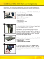
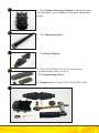
Glide Gear
DNA-1000
SET-UP AND OPERATIONS HANDBOOK
GLIDE GEAR LLC
714 Seaboard Street #9B, Myrtle Beach SC 29572 USA
www.glidegear.net
Table of Contents
SectionPage
Introduction .................................................................................................... 3
GLIDE GEAR DNA-1000 Parts and Components ......................................... 5
Assembling Your Glide Gear .......................................................................... 7
Attaching Your Camera To Your Glide Gear DNA-1000 .............................. 11
Balancing Your Glide Gear DNA-1000 .......................................................... 13
Handling Your Glide Gear DNA-1000 ........................................................... 18
Operating Your Glide Gear DNA-1000 ......................................................... 20
Shooting Tips & Tricks ................................................................................... 22
Improper Handling Techniques ...................................................................... 23
Other Camera Attachment Methods ............................................................. 24
Professional Usage ......................................................................................... 25
Maintenance ................................................................................................... 25
Warnings ........................................................................................................ 26
Warranty ......................................................................................................... 27
2
Introduction
Welcome to camera stabilization the GLIDE GEAR way! The GLIDE GEAR DNA1000 is our lightest, most compact, advanced hand-held camera stabilizer.
Designed for smaller cameras, it will perfectly accommodate anything from the
standard point-and-shoot to Mini-DV and HDV camcorders under 700 grams.
Its advanced design and engineering will transform the output of everyday
camera equipment and will allow you to produce smooth, high-quality footage
free from amateurish shakes and jerks.
The GLIDE GEAR DNA-1000 is fully equipped with all the cutting edge
balancing capabilities of other GLIDE GEAR hand-held camera stabilization
products but in a smaller and lighter package, which makes it ideal for
amateur and professional videographers alike. GLIDE GEAR Camera Stabilizers
provide unique balance and isolation; and, with the DNA-1000, even ordinary
recoding devices can get that seamless, floating, and shake-free movement.
Caught by an impromptu event at home, in the office, or anywhere else?
Shoot the occasion with the confidence of being able to perform a wide
assortment of camera movements; pan, tilt, boom, and move without any
fear of losing balance or stability. The GLIDE GEAR DNA-1000 works so
effectively that quality footage is within reach even under extreme conditions.
There’s no cause for worry anymore when shooting over bumpy terrain or going up and down steps. Imagine, it can deliver performance in such settings,
you can picture how much better your footage will be when shooting normally,
in natural walking speed or during a slow-mo movement around a subject.
The GLIDE GEAR DNA-1000 features an offset, foam-wrapped, cushioned
Handle Grip that is connected to a free-floating, three-axis Gimbal. This is
what allows the camera operator to move it from side-to-side or up and down
yet keep the camera stable; the camera is isolated from all the movement.
The Hand Grip and Gimbal together attenuate the bouncy, jumpy movement
that often results from the use of similar systems out in the market. This is
because our Handle Grip has been engineered to have this added feature: the
ability for vertical movement. This design element, combined with the overall
higher inertia of the GLIDE GEAR DNA-1000 results in greater stabilization
especially in comparison to the competition.
Its patented precision three-axis Gimbal features multiple adjustable axis
convergence controls, which allows for the compound axes to intersect for
correct alignment during operation.
3
Designed with a Camera Plate on its Camera-Mounting Platform, the GLIDE
GEAR DNA-1000 is a no-tools-required camera mount that lets you perform
quick attachment and removal of the camera. The easy to operate Control
Knobs make for simple and accurate adjustment of the platform mount’s forward and backward, and sideways movement. Through the Control Knobs, you
can easily adjust the camera’s horizontal balance.
The GLIDE GEAR DNA-1000 comes with an array of Counterweights. You can
fine-tune the camera’s vertical balance by modifying the amount of weight
on the Base Platform or through adjustments in the height of the telescoping
Central Post. A properly balanced camera on a GLIDE GEAR DNA-1000 practically floats and is ready to get into the thick of the action whenever you are.
Much sought-after features are bundled into the GLIDE GEAR DNA-1000.
Camera operators are always on the lookout for exceptional control and
maneuverability, and ease of use; and they get it all with this camera stabilizer’s exceedingly adjustable control, weight, and balance distribution areas.
Set-up, control, and adjustments on the system balance can be executed
easily and precisely.
The biggest factor in the GLIDE GEAR DNA-1000’s system is it’s compact and
lightweight makeup. Sure, it has all the features its bigger counterparts in the
GLIDE GEAR family of camera stabilizers and also makes the tripods and dollies
non-essentials in the quest for smooth and polished output, but most
importantly, it’s small, light, and easy to wield.
GLIDE GEAR continues to develop camera stabilization products for the
modern enthusiast and professional. Pushing the envelope in design and
manufacturing to ensure that more and more can have access to them.
This is also why it is fast becoming the choice of this new generation. GLIDE
GEAR now has a wide array of camera stabilizers, every one of which is
created to work best with specific camera equipment and shooting
requirements.
To achieve professional quality results with GLIDE GEAR products, some practice and a good understanding of the equipment is needed. Please read this
manual through carefully before setting up and using your GLIDE GEAR DNA1000. Reading the instructions, performing the Setup and Operation steps in
the correct order will not only lower the risk of possible accidents that may
cause damage to your equipment, it’ll also help you avoid frustration.
For further technical assistance, you may reach us at [email protected] or
call our Technical Support Lines (843)492-5283 (US) and (020)8816-7576 (UK).
4
GLIDE GEAR DNA-1000 Parts and Components
Welcome to your GLIDE GEAR experience! With your purchase of the GLIDE
GEAR DNA-1000 comes a whole new perspective on shooting and creativity!
1
1. From the box, your GLIDE GEAR DNA-1000 will
include the following:
• GLIDE GEAR DNA-1000 Manual
• Central Post with Gimbal assembly
• Camera Plate
• Camera Mounting Platform
• Telescoping Post
• Base Platform
• Counterweight Plates
• Hardware bag
2
2. The GLIDE GEAR DNA-1000 has a Central Post
with the Gimbal assembly attached.
3
IMPORTANT: Do not make any adjustments or
attempt to tighten the original factory settings on
the Gimbal, handle, and yoke. These parts need to
be able to move freely and stay loose, exactly as
they have been shipped to you.
3. These make up the head assembly of the GLIDE
GEAR DNA-1000. It includes:
• Camera Plate
• Camera Mounting Platform
4
4. The GLIDE GEAR DNA-1000’s Camera Plate is
where the camera is mounted. To take it out and
release the plate quickly from the head assembly,
turn the knobs counterclockwise and pull on them
to release.
5
5
6
7
8
5. The Camera Mounting Platform features forward
and backward, and sideways movement adjustment
knobs.
6. The Telescoping Post.
7. The Base Platform.
8. The GLIDE GEAR DNA-1000 comes with
Counterweights that consist of:
• 10 Counterweight Discs
9. Hardware set for the GLIDE GEAR DNA-1000
9
6
Assembling Your Glide Gear
NOTE: Images used for the assembly, setup, and handling sections of this manual
feature both the GLIDE GEAR DNA-1000 and DNA-5050. THE DNA-1000 is a
smaller version of the DNA-5050 and generally features the same parts and
functions. Differences in the models’ setup and functions will be duly highlighted
and specified.
11
11. Start with the Base Platform and the
Telescoping Post.
12
12. Check the bottom one end of the Telescoping
Post, it has the threaded insert.
13
13. A threaded stud attached to the center of the
Base Platform is the connection point for the
Telescoping Post. Screw in the Telescoping Post
securely to connect it to the Base Platform.
14
14. The Telescoping Post attached to the Base
Platform should look like image #14.
15
15. Locate 1 pair of bolts and attach their
corresponding washers from the hardware pack.
7
16
16. Insert the bolts with their washers into the slots
on the Base Platform. Do this for both sides.
17
17. PROGRESS CHECK: your GLIDE GEAR DNA1000 should like image #17.
18
18. Get the Counterweight Plates and slide them
through the bolts on the Base Platform. The holes
in the Counterweight Plates line up with the position of the bolts.
NOTE: Heavier cameras will need more counterweight than lighter ones.*
19
*The GLIDE GEAR DNA-1000 can accommodate devices
weighing less than 700 grams.
19. Lock the Counterweight Plates in place with
thumb nuts. Do the same for the other stack on the
other side of the Base Platform.
20
20. PROGRESS CHECK: Your GLIDE GEAR DNA1000 now has the Base Platform assembled complete with Counterweights.
NOTE: Extending the length of the Base Platform
and moving the Counterweight Plates further apart
will create pan inertia; this will slow down the
rotation of the sled and may also decrease side-toside movement while taking moving shots.
8
21
22
21. Next comes the insertion of the Telescoping
Post along with the attached Base Platform into
the Central Post.
22. Refer to image #22 to see how the Telescoping
Clamp’s adjustment knob should be aligned. To
get to this aligned position, just rotate the entire
Central Post into the correct position then tighten
the adjustment knob. Leave about an inch of the
Telescoping Post outside the Central Post under
the Telescoping Clamp. Aligning the Telescoping
Clamp’s adjustment knob as instructed does not
necessarily affect the function or balance of your
GLIDE GEAR DNA-1000, but it does make it easier
to reach when you need to use it.
23
23. Tighten the adjustment knob on the Telescoping Clamp. Tightening of the adjustment knob
should only be done by hand.
WARNING: Do not over tighten this knob.
24
25
24. PROGRESS CHECK: Your GLIDE GEAR DNA1000 should look like the one in image #24. It
will have the Base Platform and Telescoping Post
assembly properly aligned and connected to the
Central Post.
The number of Counterweight Plates you will need
will vary and will be dictated by the weight of the
camera you use. We will tackle the setting of the
correct number of Counterweights required for your
specific camera later.
25. Check the threaded insert at the top of the
Central Post.
9
26
26. Screw in the stud located at the bottom of the
Camera Mounting Platform to the threaded insert
on top of the Central Post.
The next steps shows how you are going to align
the Camera Mounting Platform so that its front
end is parallel to the front end of the Base Platform.
Correct alignment will have your GLIDE GEAR DNA1000 looking like the one in image #28.
27
27. We have two ways to adjust this alignment.
The first and simplest method is to loosen the
adjustment knob on the Telescoping Clamp and
rotate the parts until they are aligned as seen in
image #28; then, just tightening the adjustment
knob back. Keep the 1” of Telescoping Post visible
below the Telescoping Clamp as before.
28
28. Another way of correctly aligning said parts is to
use an Allen wrench to loosen the screw on the top
part of the Telescoping Clamp as shown in image
#27. Do this until you can rotate and correctly align
the parts as shown in image #28; remember to
retighten the screw.
NOTE: This method is recommended because it
leaves the Telescoping Clamp’s adjustment knob
properly aligned as in image #22. Again, while
technically it does not affect the function or
balance of your GLIDE GEAR DNA-1000, it does
make it easier to reach when you need to use it.
10
Attaching Your Camera To Your Glide Gear DNA-1000
Note: All succeeding images use the larger GLIDE GEAR DNA-5050 for
illustration purposes.
29
30
31
29. It’s now time to attach your camera to the
GLIDE GEAR DNA-1000’s Camera Plate. First,
remove the Camera Plate from the head assembly
by turning the knobs counterclockwise and pulling
on them to release.
30. Check the bottom of your camera and locate
the threaded insert.
31. Next, lay your camera on a stable surface and
place it bottom side up. Put the Camera Plate over
the camera bottom and center it as shown in image
#32.
32. Align the Camera Plate to the bottom of your
camera and make sure that it is flush against the
surface. Line up the threaded insert on the bottom
of your camera with one of the mounting holes in
the Camera Plate.
32
33
NOTE: If you’re using a camcorder or film camera
that is larger that the one shown in this manual,
you might want to first find the true front to back
center of gravity. You can do this by rolling the
base of your camera on a pencil until it is balanced
on it; mark that point on the camera’s side with a
small piece of tape, then refer to this marking to
center the Camera Plate over you camera’s center
of gravity.
33. Use a camera mounting screw and a ¼” washer
to attach the Camera Plate to your camera.
11
NOTE: Check how the shorter camera mounting
screw fits. If it does not fasten your camera
securely to the Camera Plate then try a slightly
longer mounting screw. You can also try using
more than one ¼” washer or eliminate the use of
washers altogether to get the right fit.
34
34. Place your camera on your lap or better yet,
on a stable but cushioned surface—a folded towel
on a table is a good example. Now that the
Camera Plate is in position, use a screwdriver to
affix the Camera Plate to your camera with the
camera mounting screw and the ¼” washer pair.
NOTE: Do not over tighten this screw. Doing so will
likely damage the threaded insert in your camera
base.
35
36
35. PROGRESS CHECK: Your camera and Camera
Plate should now be securely attached to each
other as shown in image #35
NOTE: If the Camera Plate can be easily rotated
on the base of your camera even when you have
adequately tightened the camera mounting screw,
and you don’t feel comfortable tightening the
camera mounting screw some more, then you
should consider using some kind of flexible “gasket”
between your camera base and the Camera Plate.
Some materials you can use are rubber tape or a
flat piece of rubber you can easily find at home—
you can, for example, cut up a piece of old rubber
household glove.
36. You can now securely place and center your
camera with the attached Camera Plate onto the
Camera Mounting Platform. Check that all knobs
are pulled all the way out before installing. Once
the plate is installed, push in the four knobs and
turn them clockwise to tighten.
12
Balancing Your Glide Gear DNA-1000
37
37. A checklist before you start the balancing process:
a) The camera is securely attached to the Camera
Plate and all four knobs are pushed in and tightened.
b) The lens cap has been removed and is secure.
c) The camera battery and video tape/disc are installed.
d) The flip out LCD is in its operating position
(if applicable, as seen in image #37)
e) The Telescoping Clamp is secure.
f) Weights have been added to the Base Platform.
38
38. Balancing the Horizontal Axis. At this point,
your GLIDE GEAR DNA-1000 is properly assembled.
You can now move on to setting up and testing
the horizontal balance of the system. You need
horizontal balance for your GLIDE GEAR DNA-1000
so it can allow your camera to stay level during
operation, given that you are not applying a pan,
tilt, or roll type of hand pressure to the GLIDE GEAR
DNA-1000.
39
In short, if your GLIDE GEAR DNA-1000 is horizontally balanced, your camera will remain level and
the Central Post will stay vertical unless intentionally
positioned otherwise. Additionally, if the GLIDE
GEAR DNA-1000 is horizontally balanced, it will
always return to a level and vertical position after
you release any pan, tilt, or roll pressure on the
Central Post as seen in image #38.
39. Testing for Proper Horizontal Balance. When
doing the test for proper horizontal balance you
have to make sure to pick up your GLIDE GEAR
DNA-1000 from a flat and level surface such as a
table; you also need to let the GLIDE GEAR DNA1000 hang freely as you hold it from the by the
Handle Grip as seen in image #38. A GLIDE GEAR
DNA-1000 that is properly balanced on its horizon-
13
tal axis will be level and upright, with the Central Post in virtually a perfect
vertical position as seen in images #38 and #40.
Chances are, your GLIDE GEAR DNA-1000 will not look as it does in images
#38 and #40. This just means that you have some adjustments to make.
WARNING: Not having enough Counterweight on the Base Platform at this
time will cause the entire GLIDE GEAR DNA-1000 to flip completely upside
down. Should this happen, add more Counterweight Plates to the Base Platform until your GLIDE GEAR remains right side up during this test.
The best method of adjusting the horizontal balance is to move your camera’s
center of gravity. You can do this in one of two ways: a) you can re-bolt the
camera to a different area of the Camera Plate or b) you can adjust the position of the Camera Plate and the Camera Mounting Platform either front-toback or side-to-side with the camera on it. Option “b” is the preferred method.
Should your GLIDE GEAR DNA-1000 tilt as it does in image #39, you then need
to loosen the thumb screws on the sides of the Camera Mounting Platform
and turn the adjustment knob counterclockwise. If the GLIDE GEAR DNA-1000
still tilts to the front, move the Camera Plate a little more to the back by turning the adjustment knob. If the GLIDE GEAR DNA-1000 is tilting to the back
instead, then move the Camera Plate to the front by turning the adjustment
knob clockwise. Always secure the thumb screws after any adjustments. If you
still cannot get the front to back axis balanced with method, then we suggest
re-mounting your camera to a different hole on the Camera Plate. When you
attain balance for the front to back axis, secure the four thumb screws on the
Camera Mounting Platform.
40
40. Should your GLIDE GEAR DNA-1000 lean
sideways, for example to the right, you will need
to loosen the thumb screws at the bottom of the
Camera Mounting Platform and turn the side-toside adjustment knob counterclockwise. Should
you notice a leftward lean—from the operator’s
vantage point—as seen in image #41, then adjust it
to the right by turning the side-to-side adjustment
knob clockwise. Remember to always tighten the
thumb screws after performing any adjustment.
A properly adjusted side-to-side horizontal axis is
shown in image #40.
14
41
41. Once you’re done adjusting the side-to-side
balance, you might have to go back and tweak the
front-to-back balance in order to get a true, fine
balance of the of the entire system. You can either
just do a visual check to judge for the correct
whorizontal balance of your GLIDE GEAR DNA-1000
or employ a lightweight bubble level (not included)
to make sure.
NOTE: The GLIDE GEAR DNA-1000’s horizontal
balance tends to be less sensitive as it becomes
more bottom heavy; conversely, the horizontal
balance becomes very sensitive as the GLIDE GEAR
DNA-1000 moves toward correct vertical balance
(more in the next section).
NOTE: Afterward, when you have adjusted the vertical balance of your
GLIDE GEAR DNA-1000, you will have to go back and readjust the
horizontal balance once more in order to achieve a true, fine balance of
the entire system.
42
42. Balancing the Vertical Axis. Now that your
GLIDE GEAR DNA-1000 is horizontally balanced,
you can turn your attention to setting up and testing the system’s vertical axis balance. The point of
having a proper vertical balance for your camera
and GLIDE GEAR DNA-1000 is so that they can stay
level during operation, given that you are not applying a pan, tilt, or roll type of hand pressure to the
GLIDE GEAR DNA-1000. Most important of all, that
the DNA-1000’s Central Post remains vertical even
when you are walking, running, or turning during
operation.
In short, if your GLIDE GEAR DNA-1000 is vertically
balanced, your camera will remain level and the
Central Post will stay vertical unless intentionally
positioned otherwise. A vertically unbalanced GLIDE
15
GEAR DNA-1000 will swing about and pendulum
when you walk, run, or turn.
43
43. Once more, if the vertical balance is properly
set, you will be able to move about quickly as well
as start or stop moving suddenly and still keep the
Central Post vertical. To adjust the GLIDE GEAR
DNA-1000’s vertical balance you can either attach
or take out Counterweights from the Base Platform, or telescope the Base Platform in or out.
When you have more or less the right amount of
weight on the Base Platform, you can fine-tune the
vertical balance further by using the Telescoping
Post.
NOTE: The GLIDE GEAR DNA-1000 swinging
between horizontal and vertical during the “Sled
Arc Test” as seen in image #43.
44
44. The Sled Arc Test is performed to check the
balance of the vertical axis. Doing the Sled Arc Test
is as simple as holding the GLIDE GEAR DNA-1000
by its Handle Grip, pulling the Base Platform up
and back until the Central Post is horizontal and
motionless as in image #42, then gently letting the
Base Platform go. After that, you need to take note
how many seconds it will take for the GLIDE GEAR
DNA-1000 to go from the horizontal position is was
just in as shown in image #43, to the moment it
first passes the vertical position, see image #44.
A vertically balanced GLIDE GEAR DNA-1000 will
take approximately two to three seconds—also
known as “Drop Time”—to pass the vertical position. Make sure to count your seconds by reciting
them to beat like: one one thousand, two one
thousand, and so on for better accuracy. Adjust
the number of Counterweight Plates on the Base
Platform or lengthen or shorten the Telescoping
Post until it takes only two to three seconds for the
16
GLIDE GEAR DNA-1000 to swing in an arc from horizontal to vertical.
NOTE: The length of Drop Time set will, in the end, be up to you to decide.
Different Drop Times affect the vertical balance and as a result, will change
the obtainable shooting output.
An alternative method to check for proper vertical balance is the “Movement
Test.” It requires moving forward with the GLIDE GEAR DNA-1000 and suddenly stopping. If the abrupt movement causes the its Base Platform to swing or
pendulum away from you or from the upright vertical position it was previously
in, then you have confirmation that it is not vertically balanced. Adjust the
number of Counterweight Plates on the Base Platform, or lengthen or shorten
the Telescoping Post until the GLIDE GEAR DNA-1000 stays vertical during the
Movement Test.
This test also applies to running or turning around abruptly while holding the
GLIDE GEAR DNA-1000. Again, movements such as running or quick turns will
not affect a vertically balanced DNA-1000’s basic, upright position.
Image #44 shows the GLIDE GEAR DNA-1000 swinging past an illustrated vertical line. During a Sled Arc Test, the GLIDE GEAR DNA-1000 will swing or pendulum past this line over a dozen times if left alone; but, it is only the initial
swinging in an arc movement that you need to concern yourself with. When
you have counted the time it takes for the GLIDE GEAR DNA-1000 to go from
horizontal to passing the vertical once, you can stop the test. You can either
put down the GLIDE GEAR DNA-1000 or make your adjustments and perform
the test again.
NOTE: Adding more Counterweight Plates or lengthening the Telescoping Post
will speed up the Drop Time. Taking out Counterweight or shortening the
Telescoping Post will slow down the Drop Time.
17
Handling Your Glide Gear DNA-1000
Knowing how to correctly handle your GLIDE GEAR DNA-1000 is a must prior
to shooting or filming any project. In the operation of the your DNA-1000, one
hand will be used to hold the Handle Grip and the other, to guide the camera
in the direction you want to shoot. For clarity’s sake, let’s call the hand on the
Handle Grip the “Grip Hand” and the hand that directs the camera’s movements
such as tilting, panning, etc., the “Guide Hand.”
45
45. There are a couple of things you need to do to
properly handle your GLIDE GEAR DNA-1000 and
they are: 1) grip it firmly, and 2) take hold of it
either in the middle or near the bottom of the
Handle Grip. The position you pick will depend
on the type of shots you need to take. For normal
shooting, it is best to grip the handle in the middle
as in image #45. For shots that require pointing the
camera up, down, or sideways best to grip it firmly
at the bottom; doing so will allow the “yoke” of the
Gimbal to twist and move around without hitting
your hands or knuckles.
46
46. As you handle your GLIDE GEAR DNA-1000,
you will want to use your Guide Hand to lightly hold
onto either the point just under the yoke and bearing assembly as seen in image #46, or a spot down
by the Base Platform as seen in image #53. When
using your GLIDE GEAR DNA-1000, these two areas
allow for the easiest and best control. Again, the
hand position you pick will depend on the type of
shots you need to take.
Observe how the Guide Hand does not touch the
yoke or main bearing assembly.
47. Normal shooting will require that you hold the
GLIDE GEAR DNA-1000 with your Guide Hand at
the spot just underneath the yoke as seen in
18
image #46. Handling it this way will allow you to subtly aim your camera while
maintaining the camera’s upright position. This is the position that will let you
shoot the smoothest footage when walking or running with the unit during
normal shooting.
NOTE: Take note that your Guide Hand and Grip Hand do not touch the bearing assembly or yoke while shooting; doing so can lead to unsteady shooting.
Irregular or unconventional shots such as those that require pointing the camera straight up or down, or sideways will need you to hold the GLIDE GEAR
DNA-1000’s lower portion or by the Base Platform as seen in image #53. This
will give your Guide Hand a higher measure of control over the unit even while
shooting erratic shots and angles.
19
Operating Your Glide Gear DNA-1000
48
48. The GLIDE GEAR DNA-1000 is designed for
two-handed operation as seen in images #46 and
#48. Operating it with your Grip Hand alone, the
camera is likely to drift away from its original
position as you shoot. Your Guide Hand is essential
in controlling the camera’s direction.
49
49. In the operation of the GLIDE GEAR DNA-1000,
you will not be able to use the viewfinder.
Putting your eye right next to the viewfinder’s
eyecup will hamper the stabilization capabilities of
the GLIDE GEAR DNA-1000. It is best to use the
camera’s built-in LCD monitor as shown in image
#54. Another option is to attach a separate external
monitor directly to the Base Platform. This monitor
“mounting hole” can be found at both the front and
back edges of the Base Platform.
50
50. While we think attaching an external LCD
monitor to the Base Platform is a better option
because it will encourage you to look down to
check on it more often—and therefore, get more
opportunities to look at where you’re going and
make getting around obstacles in your path safer—
you can opt to attach the external LCD monitor to
the accessory shoe on top of your camera.
NOTE: Images #49 to #51 show the GLIDE GEAR DNA-1000 held and
used in different ways.
20
51
51. Putting your GLIDE GEAR DNA-1000 to use
for extended periods of time can fatigue you Grip
Hand easily. Should tiredness set in while you’re in
the middle of a shoot, you can try switching hand
roles in the operation of your GLIDE GEAR DNA1000 —swap your Grip Hand with your Guide Hand
and vice versa. Or, you can opt to take a break and
rest for a bit by placing the unit upright on a level
surface or laying it on the ground; if you’re using
the bracket, you can also dock the sled.
GLIDE GEAR also has separate accessories for the
DNA-1000 that can address your need for help in
handling the unit for longer periods of time. Check
out our website: www.glidegearhdslr.com or give us
a call to learn more.
52. In the handling or operation of your GLIDE
GEAR DNA-1000, be aware and steer clear of
sudden and forceful movements such as a violent
jerking motion with your arm and similar actions.
Performing such can cause damage to the unit
and possibly even get your camera loose from the
Camera Plate.
53. The GLIDE GEAR DNA-1000 is not made for
underwater shooting; it does not work underwater.
The unit is not waterproof. You are advised to avoid
direct exposure to rain and water spray. Also, the
GLIDE GEAR DNA-1000’s bearings are sensitive
to dirt and sand, so avoid getting any into them.
Refer to the bearing maintenance section for more
information.
21
Shooting Tips & Tricks
54
54. When using a standard consumer camcorder you will likely notice that the
widest focal length setting on such units are not sufficient to replicate looks
often shot with professional cranes, dollies, and stabilizers; but, there is a
workaround. Using a wide-angle lens converter over your standard camcorder
lens when shooting should take care of this.
55. Walking the Line. “Walking the line” is an exercise designed to help you
use your GLIDE GEAR DNA-1000 more accurately. All you will need is some
masking tape, camera, or gaffer’s tape. First, create a cross mark on a flat
wall; this mark will be for framing purposes. Next, lay down tape in a straight
line on the floor leading up to the cross mark; this line should be around 10
to 20 feet long. Then, the exercise will proceed with you walking the line you
laid down on the floor and keeping the cross mark on the wall centered on
your LCD monitor as in image #54. The objective of this exercise is to train
you precision framing during a shoot.
22
Improper Handling Techniques
56
57
56. Do not clutch the Central Post
when shooting with the GLIDE GEAR
DNA-1000 as seen in image #56. Doing
so voids the principle of the thee-axis
Gimbal and the isolation it provides.
Refer to images #46 and #48 for proper
handling of your GLIDE GEAR DNA1000.
57. Do not let the Handle Grip to come
into contact with the Camera Mounting
Platform as seen in image #57. Such
contact will limit your range of motion
and will lead to shaky, jerky, and
possibly unusable footage. Remember
to position the Handle Grip as shown
in image #45.
23
Other Camera Attachment Methods
Create a Gasket. In case your camera does not have a true flat and level
bottom to allow for full contact with the Camera Plate, getting it solidly
attached can become an issue. Making and adding a paper/cloth or rubber
gasket to the Camera Plate can easily resolve this. Using the Camera Plate as
pattern simply cut the material (such as a piece of rubber dishwashing glove)
and make a hole in it to let the Camera Mounting Bolt through and into the
base of your camcorder’s threaded insert.
24
Professional Usage and Maintenance
PROFESSIONAL USAGE
Using the GLIDE GEAR DNA-1000 to achieve professional output, perhaps in
taking shots or footage you’d like to incorporate into a movie or some type of
commercial project, we highly recommend plenty of pre-planning and maybe
even rehearsing your shots before the actual shoot. Having an assistant,
especially during complicated shots, will increase your chances of getting the
professional look you’re aiming for.
Good luck and enjoy shooting with your GLIDE GEAR DNA-1000.
MAINTENANCE
Cleaning. Cleaning your GLIDE GEAR DNA-1000 is simple. If or when the unit
gets dirty, just use a water-dampened cloth or sponge to gently wipe it clean.
Do not use solvents or harsh cleaners of any kind.
Bearing Maintenance. Your GLIDE GEAR DNA-1000’s main bearing is connected to the Central Post, approximately two inches from the top. The main
bearing is metal and is partly enclosed by the bearing assembly. If after some
time this bearing does not quite turn as smoothly as it originally did, you can
thinly coat it with light lubricating oil. Remember, you just need to use a very
small amount of oil, anything more than that will just ooze out of the bearing
and onto to your GLIDE GEAR DNA-1000. You can also use the light lubricating oil for your GLIDE GEAR DNA-1000’s yoke and handle bearings. Take care
to safeguard your camera from the oil by checking and cleaning up any spill
over when you’re done.
Storage. When storing your GLIDE GEAR DNA-1000 for long periods of time,
remember to keep it upright and in a dry or low to normal humidity area as
much as possible. If you cannot be sure of the environment’s humidity conditions, we then suggest that the unit be stored in an airtight plastic container or
bag. Storing the unit upright helps in alleviating the stress on the system.
25
Warnings
Take care when using your GLIDE GEAR DNA-1000 at night, in low light
conditions, and in uneven or unfamiliar terrain. A dangerous and bad mistake
you can make is focusing so much on what you’re shooting and not seeing
the hazards along your path. You can trip, fall over, or slip on something; or,
stray into a dangerous area like a street with busy automobile traffic, a deep
pothole or even a swimming pool. Extra care is also necessary when tackling
stairs and other kinds of uneven ground. These warnings apply to shooting in
daylight and well-lit areas.
Minors using this product should have adult supervision. If you intend to shoot
while moving fast, or while traversing uneven terrain, do not hesitate to wear
protective gear such as knee and elbow pads, a helmet, and eye protection.
26
Warranty
We will repair or replace you GLIDE GEAR DNA-1000, free of charge, in the
event of a defect in materials or craftsmanship obtained during normal use or
handling based on the GLIDE GEAR DNA-1000 user’s manual for ninety (90)
days from date of shipment (shipment date appears on your purchase receipt).
Shipping, packing, and insurance costs to and from the factory will be your
responsibility.
This limited warranty is available only to the original buyer and proof of purchase in the form of the original receipt is required.
The warranty does not include, by way of example, damage cause by products
not supplied us or damage resulting from mishandling in transit, accident, misuse, neglect, vandalism, modification, lack of reasonable care (pertaining to
units for commercial use, including rental to others) of the GLIDE GEAR DNA1000, or service by anyone other than our company. We offer no express warranties except as listed above. This warranty awards you specific legal rights.
You may also have other rights that may differ from state to state.
GLIDE GEAR is not liable for incidental or consequential damages resulting
from the use of the unit or occurring due to any breach of this warranty. All
express and implied warranties, including the warranties of merchantability and
fitness for a particular purpose, are limited to the ninety (90) day warranty
period.
To get service during or beyond the warranty period, you may get in touch
with us through [email protected] or call us at (843) 492-5283 (US)
and (020) 8816-7576 (UK).
Do not send the unit to us without first getting a response and acquiring a
return authorization number.
For more information on GLIDE GEAR product performance and training,
visit the GLIDE GEAR website.
www.glidegear.net
27
Glide Gear
GLIDE GEAR LLC
714 Seaboard Street #9B, Myrtle Beach SC 29572 USA
www.glidegear.net