1
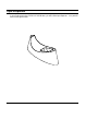
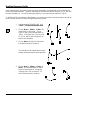
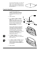
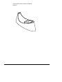
Draft the Dispenser Profile
Since constructing this part requires some precise point placement, we thought that color coordinating the
points would ease the process. Therefore, some steps will use both the name of the point (P1, S1, etc.) and
the color allocated to it. You will be making the majority of your part using the Attribute LTBLUE.
To build the initial cross sections of the dispenser, you are going to construct a spline through a set of given
points, and then construct an ellipse through a second set of points.
1. Load the drawing DSPNSR.DWG, click
on Edit > Surfaces and boolean solids.
2. Click on Draw > Spline > Create. Set
-Input Style? to ‘thru points’, -Curve
Type? to ‘open’ and -Attribute Name? to
‘violet’. In the front view, click on points
P1, P2, P3, and P4 (the violet points), as
shown in the illustration.
3. Click on Done in the Spline Function box
to accept the points for the spline.
The illustration to the right shows the spline
created, passing through the points specified.
4. Click on Draw > Ellipse > Center, 2
Points. Set -Attribute Name? to ‘ltblue’
and set -Ellipse Extent? to ‘full ellipse’.
In the top view, click on points P1, P2,
and P3 (the blue points), as shown.
CADMAX User's Manual
Boolean Solids Tutorial / 3


![[ol-rs-ha6]-en - Sonic Electronix](http://vs1.manualzilla.com/store/data/005843713_1-a0736ea4d1b526b61217546e349ee9ef-150x150.png)