1
1
Table of Contents
Introduction
Section 1.0 Plant Routine Inspection and Service Instructions
Section 2.0 Operating Instructions
Section 3.0 Diffuser Stone Replacement
Section 4.0 Plant Troubleshooting Guide
Section 5.0 Hydro-Action® Industries AP-Series Plant Specifications
Section 6.0 Process Description
Section 7.0 Safety
Appendix 1: OPS Explanation Guide
Appendix 2: Technical Manual for Air Pumps
Appendix 3: Technical Manual for Timers
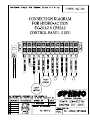
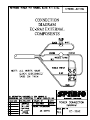
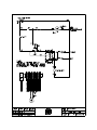
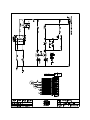
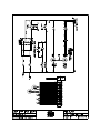
Appendix 4: Electrical Controls Schematics
Appendix 5: Drawings
Appendix 6: Misc. Forms & Documents
Appendix 7: NSF Certification & Responsibilities
Introduction
The AP Series Aerobic Treatment Units
(ATUs) are now available through HydroAction®. Please read this introduction
before reviewing this manual.
facilities. The improvements in these units
make them not only extremely efficient
operational units but also the most easily
maintainable system in the industry.
Earth’s environment has purified water
through natural processes since the
beginning of time. Only recently, beginning
in the Twentieth Century, has man
developed a system to accelerate the
processes that Mother Nature uses. HydroAction® AP Series ATUs are just such
systems.
By following the instructions in this manual,
you will be providing yourself with the best
on-site wastewater treatment and service.
We invite you to share in our pride of the AP
Series Treatment Units.
In 1916, the City of Houston, Texas, was
the first to use the activated sludge
wastewater treatment process as an
accepted, full-scale system process to purify
domestic wastewater. Since that time, the
United States and many other nations have
utilized this process and variations to
properly treat sewage. Federal Law 92-500
supports our nation’s commitment to
provide secondary treatment for all
domestic wastewater.
This commitment is presently being
extended to on-site sewage treatment
facilities. Hydro-Action® has been a visible
part of this effort since 1989. We have
manufactured numerous products to provide
individuals with a means of proper,
effective, efficient, and affordable on-site
wastewater treatment. Our professional
commitment to market needs and customer
service have enabled us to reach our goal
of providing effective products that assure a
safe, reusable effluent. We are helping
Mother Nature protect our environment and
our most valuable natural resource: water.
Our continuing mission is to develop and
manufacture individual on-site wastewater
treatment facilities that meet society’s needs
in the field. This manual is a part of that
dedication to customer service.
Hydro-Action® AP Series Aerobic
Treatment Units are among the most
advanced on-site products available today.
They are state-of-the-art extended aeration,
activated sludge wastewater treatment
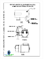
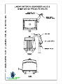
This manual includes information on the AP500, AP-600, AP-750, AP-1000G & AP1500G wastewater treatment plants. These
units may be installed with either a platform
mounted OPS® (operations/control center)
or a Remotely Located OPS®. Installation
needs vary, so your on-site wastewater
system may contain some of the following
auxiliary components along with the
treatment plant:
• Pretreatment tank
• Pump/holding tank
• Alarm systems
• Equipment for chosen effluent disposal
method (drip irrigation, spray irrigation,
gravel-filled drain field, pressure dosing,
etc.)
• Chlorinator / UV Disinfection Unit
The certified Hydro-Action® dealer or
installer of your Hydro-Action® AP Series
wastewater treatment plant is responsible
for completing and submitting to us the
Installation Warranty Information to properly
activate your Hydro-Action® Product
Warranty.
We are eager to assist you with any
questions or problems. Please contact
Hydro-Action® at 800.370.3749 to request
assistance from our Customer Service or
Engineering Departments
SECTION 1.0: Plant Routine
Inspection and Service Instructions
1.1: Each site should be inspected and
serviced by following these simple
instructions. As each state may have
differences due to selected disposal
options, refer to our website and inspect to
determine which options are present then
proceed with the following instructions.
1.1.1: Upon arrival at the site, remove the
tamper-resistant screws from the HydroAction® plant access cover and the
Platform Mounted OPS® or Remotely l
Located OPS® enclosure. Then remove the
access cover and enclosure. Set the
security screws and covers in a protected
place for later reassembly.
1.1.2: Collect an activated sludge sample
from the aeration compartment. The sample
size should be approximately one quart.
Collect the sample as soon as possible; you
can perform other work while the solids are
settling and thereby reduce your inspection
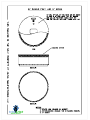
time at the site. Use this sample to run the
sludge volume test (15 minutes settable
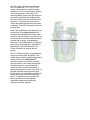
solids ml/L test). To perform this test a oneliter graduated cylinder or any tall, straightsided, clear glass container, about onequart in capacity, will be needed. Divide the
container into 10 equal parts using a
waterproof marker, thus signifying 0 to
100%.
a. Immediately after sample is collected, fill
graduated container to 100% mark.
b. Allow sample to stand for 15 minutes.
c. Measure sludge volume by locating
interface between clarified effluent and
settled sludge on graduations. Interface
should be between the 20% and 60%
marks, indicating a well-functioning plant.
Values less than 20% or greater than 60%
indicate there is a problem. Sludge layer
should be chocolate in color and full of very
small particles resembling small pieces of
sponge. Refer to the Hydro-Action® Plant
Condition Chart, section 4.12.
1.1.3: As turbulence in the aeration
compartment caused by the rising fine air
bubbles can be seen, observe any
significant changes in mixing and aeration
characteristics. If insufficient mixing or poor
aeration is observed, refer to Section
1.1.4a. Both diffuser assemblies should
appear to have equal turbulence. This is an
indication of proper diffuser assembly and
diffuser operation.
1.1.4: Proper aeration in the Hydro-Action®
AP-Series is maintained by performing the
following maintenance operations:
a. Clean or replace the air pump inlet/outlet
filters during routine inspections; inspect the
aeration compartment surface through the
access port to determine the amount of
turbulence caused by air coming from each
diffuser assembly. Both diffuser assemblies
should appear to have equal turbulence.
This is an indication of proper diffuser
assembly and diffuser operation.
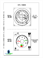
b. Locate the Schrader air pressure valve
on the PVC air pump discharge line.
Unscrew the protective cap and connect the
quick chuck pressure gauge. Read and
record the pressure. If the pressure equals
or exceeds 3.5 psig, it is time to replace the
air diffuser stones on the diffuser
assemblies (refer to Section 3). After
pressure reading is complete, remove the
quick-chuck pressure gauge and replace
the protective cap on the Schrader air
pressure valve.
Note: Whenever replacing the HydroAction® diffuser stones, replace all
stones—not just a few. Replacement parts
can be obtained from Hydro-Action®.
1.1.5: To replace air diffuser stones, refer to
Section 3.0.
1.1.6: Using a clean, clear sample bottle
catch an effluent sample from the pump
tank or other discharge point. Effluent
should have a non-offensive odor and be
clear in color. If results differ from these
refer to section 4.0, Plant Troubleshooting
Guide.
1.1.7: Check the surface of the clarification
compartment for floating solid or scum
buildup. If build-up is found, remove it using
a small net with very fine mesh and dispose
of off-site according to all federal, state, and
local regulations. (Material may be returned
to system upstream of plant through
cleanout.) Using a garden hose, spray a
high-pressure stream of water into clarifier,
breaking up any remaining floating solids.
Clean any over spray from the general area.
1.1.8: Activate liquid level alarm by raising
and lowering float in clarifier to test both
audible and visible alarms. Disrupt the air
pressure by disconnecting the air pressure
tubing from the electrical enclosure inside
OPS® to test air pressure alarms. If any
problem is experienced with alarm
functions, make necessary adjustments,
corrections, and/or repairs. If optional
remote alarm has been installed, be sure
that its audible and visual alarms are also
working correctly.
1.1.9: The switch indicated “normal/silence”
on OPS® models 50-11, 20, -30 & -32 is
used to test the alarms, silence an alarm
condition, or is left in the normal on position.
The normal position of the mode is for
normal operation of the plant and silence is
a mode that will disrupt both the audible and
visual alarm. Move the switch to the left and
hold to test the alarms. The test switch will
reset itself automatically. These alarms
should always be tested before leaving the
site to assure they are operational.
1.1.10: If optional effluent pump is included
on system, activate pump float switch to
assure effluent pump is operational; set and
adjust timers as required (if installed).
1.1.11: Reinstall Hydro-Action® access
covers being sure to install and tighten
tamper-resistant screws to prevent
unauthorized plant entry.
1.2: Each site visit requires an investigation
of the solids inventory within the wastewater
treatment plant and a determination of when
excess solids need to be removed from the
system. Follow these procedures in
evaluating solids inventory:
a. Hydro-Action® plant inspection and
service should be performed a minimum of
every six (6) months. This inspection and
service includes performing a sludge
volume test, which is an indicator of plant
performance. (Refer to section 4.0, Plant
Troubleshooting Guide.)
b. When sludge volume in plant aeration
compartment reaches 60% to 80% it is time
to pump the plant and pretreatment tank (if
included). This is usually necessary every
two (2) to six (6) years.
1.3: Follow these procedures to pump the
sludge solids from the treatment tanks. A
qualified service technician should oversee
the work performed.
1.3.1: Remove the plant access cover.
1.3.2: Refer to installation worksheet to
determine which tanks and auxiliary
equipment are included on this particular
installation (i.e., pretreatment tank, surge
tank, pump tank, access covers of different
units). Remove pump tank access cover (if
included). If necessary, use a shovel to dig
down and expose the pretreatment tank
access covers and remove them. Remove
the clean-out adapter plug from the outlet
tee fitting. The tanks are now ready to be
pumped.
1.3.3: The suction hose should be
positioned to be very near the bottom of the
tanks. Care should be taken not to damage
internal components. The plant and other
tanks should be washed and cleaned while
they are being pumped. The waste from the
tanks should be disposed of in compliance
with local, state, and federal laws.
1.3.4: It is important that care is taken when
pumping plant and any other tank to assure
that hydraulic displacement of tanks
(floating of tanks) does not occur. Tank
flotation may occur whenever water and
solids are removed from the tank when high
groundwater conditions exist. Any source of
water in the soil around the plant installation
could cause the tank to float. Water sources
may include rainfall, springs, creeks,
bayous, rivers, lakes, and coastal areas.
Proper precautions are therefore required to
prevent tank flotation due to hydraulic
displacement.
Note 1: The owner has been informed that
replacement parts can be obtained from a
Hydro-Action® Certified Dealer.
These precautions include, but are not
limited to, the following:
Note 2: Pumping the plant is usually
necessary every two (2) to six (6) years;
however, there is no set time because
loadings vary from household to household.
Access to the plant is accomplished through
the access opening, which is at surface
grade. When a Hydro-Action® plant is
being pumped, a qualified service
technician should oversee the job. Care
should be taken not to damage internal
components. The plant should be washed
and cleaned while it is being pumped. The
waste from the plant must be disposed of in
compliance with all federal, state, and local
laws.
• Plant location — choose a site that will
minimize possible groundwater saturation.
Consider seasonal water table and soil
conditions in the area of installation. Do not
locate the plant in a low spot in the ground
where water tends to pool or at the edge of
any natural body of water. If such a location
cannot be avoided, call Hydro-Action® for
technical advice.
• Whenever a tank is pumped, do not
remove more than one-half of the capacity
of the tank. It is recommended that you
pump the tank during dry seasons only.
However, if tank must be pumped during the
wet season, watch for upward movement of
the tank while pumping is being done. If
upward movement is detected during pump,
immediately stop pumping water out of
the tank and refill the tank to stop
flotation. Each site must be evaluated on a
case-by-case basis to determine the best
time to remove water from the tank and
prevent flotation.
1.3.5: Replace the pre-treat, plant access,
and pump tank access cover (if included),
being sure to reinstall and tighten the
Hydro-Action® tamper-resistant screws to
prevent unauthorized plant entry. Note:
Plant and other tanks should be filled with
water before leaving site.
1.4: Normal maintenance on the HydroAction® AP Series plant will include:
Every Six (6) Months:
a. Maintaining aeration system and air
diffusers.
b. Maintaining air pump.
c. Removing scum from clarifier.
d. Inspecting and testing plant alarms.
Every Two (2) to Six (6) Years:
e. Pumping excess sludge from plant.
SECTION 2.0: Operating Instructions
2.1: The Hydro-Action® AP Series Plant
has been designed and built to provide
efficient, dependable, and reliable service.
However, as with any individual wastewater
treatment plant, routine periodic service is
required. When proper preventive
maintenance is performed, the HydroAction® plant will operate at designed
performance levels to give years of
satisfactory treatment of domestic
wastewater.
2.2: Local Hydro-Action® authorized
representatives are required to perform all
routine inspections for the first two (2) years
from the original date of installation. At the
time of inspection the plant will be checked for
proper operation. If a problem exists, service
will be performed at no charge to the owner,
unless the required maintenance is not warranty
related. At the end of the two (2) year initial
service period, the local representative will
make available a continuing service policy. This
extended service is available for a nominal
fee. Rep will also provide O&M agreement as
well as a copy of the warranty policy.
2.3: The Hydro-Action® OPS®
(Operations/Control Center) is equipped
with an alarm beacon and an audible horn
alarm. Also on the OPS® should be the
name, address, and telephone number of
the local servicing dealer. An optional
remote alarm with audible and visual alarms
may also be present. Should either alarm
come on, the owner is instructed to call the
local dealer. After a power failure, if an
alarm remains on for more than 30 minutes
the owner is instructed to call the local
dealer immediately. To silence audible
alarm while waiting for service technician to
arrive, owner should locate the switch on
outside face of the OPS® enclosure labeled
“normal/silence” and push it to the “silence”
(right) position. Visual alarm beacon will
remain illuminated.
2.4: The Hydro-Action® AP-Series Plant
will handle all domestic wastewater. The
term domestic wastewater refers to rapidly
biodegradable material. To keep
maintenance at a minimum and to prevent
the plant from malfunctioning, the following
guidelines need to be followed:
• Since aerobic bacteria are responsible for
treating the wastewater, inorganic or nonrapidly biodegradable materials should not
be put into the plant. Examples of improper
items are: plastic products, rubber products,
sanitary napkins or tampons, washcloths,
cigarette butts, melon seeds, coffee
grounds, egg shells, matches, some food
items such as corn husks, grape vines, etc.
• Do not introduce cooking grease or large
amounts of oil into plant; instead pour it into
a container and dispose of it properly.
• To minimize pump-out frequency, limit use
of garbage disposals.
• Lint from lint catchers, hair, etc., should be
disposed of in the trash and not washed
down the drain.
• Water softener backwash should not be
routed through the system. Another source
of disposal should be used. Check our state
specific portion of our website for bypass
method to be used.
• Diapers can be rinsed out in the toilet;
however, do not flush cloth or disposable
diapers down the toilet.
• Large amounts of harsh chemicals, high
foaming detergents, disinfectants or any
substance that kills bacteria must not be
discharged into the plant.
• The plant will not perform to its fullest
capabilities if volumetric overload is allowed
to occur. This occurs whenever excessive
water, above the designed flow rate, is
allowed into the plant. Excessive water use
or leaking plumbing fixtures may cause this
condition.
Hydro-Action® Authorized Representatives
& Technicians are asked to inform
homeowners of these guidelines. Too often a
malfunctioning treatment unit is due to
abuse that can be avoided with simple
education.
2.5: Other than for the mechanical and
structural working of the plant itself, HydroAction® is not responsible for the in-field
operation of a plant. The proper operation of
this or any other individual wastewater plant
depends upon proper organic and hydraulic
loading of the plant. We cannot control the
loading and thereby control the amount of
harmful substances that may be discharged
into the plant. Only the users of a plant can
control what enters the unit. Therefore, we
provide a comprehensive owner’s manual
that outlines substances that should be kept
out of the plant.
2.6: The Hydro-Action® AP-Series must be
installed and maintained according to
factory specifications. No modifications of
equipment or design are allowed.
Modification of the plant will void warranty
and invalidate NSF certification of plant.
2.7: OPS® models 50-30 or 50-32 include a
Omeron micro-dose timer. The micro-dose
timer is utilized in drip applications. The 50-30
is a 24-hour time clock with 15 minute
incremental settings. The 24-hour timer is
used in spray or light dosage applicationss.
If for some reason their is a loss of power,
the timers may need to be reset. However,
the treatment plant will immediately begin
rejuvenating. See the Technical Manual
section of timers in Appendix 3.
SECTION 3.0: Diffuser Stone
Replacement
3.1: With plant access cover removed,
reach in and disconnect the flexible airline
hoses from retainer clamps. Then remove
diffuser assemblies through the plant
access opening.
3.2: Disconnect and remove diffuser
assemblies from the flexible airline hoses.
Remove diffuser assembly locknuts,
gaskets, and diffuser stones. Now wash and
clean all diffuser assembly components.
Discard original diffuser stones and replace
with new ones. Reassemble and reconnect
the diffuser assemblies in reverse order,
lubricating all gaskets and making sure all
gaskets and check valves are in the proper
place and in good condition before
tightening.
3.3: Reattach the diffuser assemblies to
flexible airline hoses and reattach flexible
airline hoses to retainer clamps. Replace
diffuser assemblies into Hydro-Action®
plant by lowering the diffuser assemblies
with attached anchor to the bottom of
aeration tank.
Note 1: Securely tighten all connections by
hand being sure not to over-tighten and not
to push the gaskets out of the gasket seat
areas. All connections must be properly
sealed to assure trouble-free diffuser
operation.
Note 2: Diffuser stones are to be replaced
whenever the pressure reading at the
schrader valve on the discharge side of the
air pump equals or exceeds a reading of 3.5
psig on AP Series.
SECTION 4.0: Plant Troubleshooting
Guide
4.1: The Hydro-Action® AP Series plant
has proven to be very effective and reliable
in the treatment of domestic wastewater.
The problems outlined here occur only in a
very small percent of total installations.
They can all be corrected and most can be
prevented.
4.2: When the owner/user calls, ask him or
her to describe the problem in detail and
determine the plant age and service history
from your records. This information is then
used in preparation for the service call.
4.3: First perform a routine service call as
described in section 1.0, Plant Routine
Inspection and Service Instructions.
4.4: If routine servicing does not solve the
problem, go through the steps listed below.
4.5: Verify model number of plant and OPS®
with those in records. If this is a new
installation, you should verify that the plant
and all its components were installed
correctly and in accordance with
manufacturers and regulatory agency
requirements. See Hydro-Action® AP
Series Installation Manual, available from
Hydro-Action®.
4.5.1: Inspect plant to verify that the HydroAction® plant is installed properly and is not
damaged. Plant should be level and internal
components should be in proper place and
correct working order. Please fill out the
Installation Checklist.
4.5.2: Check to see that effluent disposal
method is allowing for proper level to be
maintained in plant. High level in plant can
adversely affect performance.
4.6: After confirming that Hydro-Action®
plant is installed properly and is not
damaged, check the operational and
maintenance conditions of the plant to
determine if it is performing correctly. To do
this run a sludge volume test as described
in section 1.0. compare your findings with
the conditions given in the Hydro-Action®
Plant Condition Chart, section 4.12. Follow
the recommended actions required to return
the plant to its proper operating conditions.
4.7: The alarms supplied with this
wastewater treatment plant provide the
owner with a secure, reliable, dependable,
and economical means of notification for
most malfunctions of the plant that would
lead to producing an unsatisfactory effluent.
These alarms include notification for
problems of air pump failure, aeration piping
malfunctions, and high water level. These
alarms need to be inspected and tested
during each plant operation and
maintenance site visit. If an optional remote
alarm has been installed, it should also be
inspected and tested during each site visit.
4.8: To gain access to the electrical controls
and air pump, remove the security screws
holding the OPS® enclosure to the base.
4.9: The switch indicated “normal/silence”
on OPS® models 50-11, 20, -30, & -32 is
used to test the alarms, silence an alarm
condition, or is left in the normal on position.
The normal position of the mode is for
normal operation of the plant and silence is
a mode that will disrupt the audible alarm.
Move the switch to the left and hold to test
the alarm. You should see and hear the
visible and audible alarms when this mode
is selected. The OPS® switch will reset itself
automatically.
4.10: If the audible and visual alarms on the
outside face of the Hydro-Action® OPS®
enclosure are indicated the problem might
be failure in power supply or air pump, or an
electrical short in the line between electrical
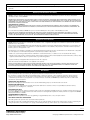
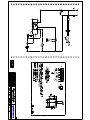
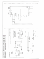
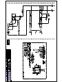
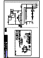
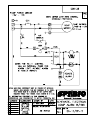
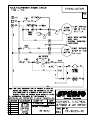
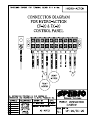
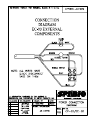
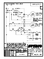
controls and air pump. See Appendix 5,
Electrical Controls Schematics, for details of
each model. See Appendix 2, Operation &
Maintenance Technical Manual for Air
Pumps for details on working with air
pumps.
4.11: The AP-Series plant is equipped with
a high-level float switch and alarm. If the
system also includes a pump/holding tank to
remove effluent, the Hydro-Action®
electrical controls may include a second
high-level alarm. If the owner reports highlevel alarm light on, service technician
should be sent to correct the problem. A
malfunctioning water pump or level float or a
plugged discharge could cause the high
level conditions. A malfunctioning high-level
sensor float could give a false high-level
alarm. This problem left uncorrected will
lead to system failure and improper
wastewater treatment and therefore
requires immediate attention.
This section intentionally left blank.
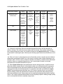
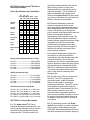
4.12: Hydro-Action® Plant Condition Chart
®
Hydro-Action Condition
Organic
Over loading
Organic
Under loading
Toxic
Influent
Volumetric
Overloading
Well Functioning
Sludge Volume Test
Characteristics
Black particles
In sludge.
Solids do not
separate
from liquids well.
Septic odor.
Same
as
organic
under
loading.
20-60%
particles.
Sludge does not
settle well.
Chunks of
floating material
above main
sludge layer.
Very little
settling usually
5-10 %.
Very little
settling.
Sludge
particles
are
very small.
Particles
resemble
small
pieces
of sponge.
Color
Gray Black
Light Muddy
Gray
Grayish
Black
Light Muddy
Gray
Chocolate
Action needed
Diffuser stones
may need to
be changed
to increase
dissolved O 2
level and
maintain
chocolate color.
Look for
ways
to increase
organic
load.
Refrain
from
or reduce
the use of
toxic
substances.
(*2)
Reduce flow
of liquid to
designed GPD.
(*1)
None
If chocolate
color cannot
be maintained,
then the plant
will have to
be pumped.
(*3)
*(1). Volumetric overloading (flow rate exceeds designed flow rate) could be caused by a
number of things. The most common are leaky toilets or faucets. Only sanitary waste (sinks,
tubs, washing machines, toilets, etc.) should be allowed in the Hydro-Action® plant. To check if
excess water is entering the plant, observe plant discharge point when house facilities are not in
use.
*(2). Find out if owner is using large amounts of chemicals such as unusual amounts of bleach,
disinfectants, photographic wastes, etc. Also check to see that water softener backwash is not
allowed in plant. This can cause a chemical imbalance and destroy needed bacteria. Backwash
should be routed to a separate disposal area. Any unusual types of waste not normally
associated with a household should be kept out.
*(3). When Hydro-Action® plant and pretreatment tank are being pumped, a qualified service
technician should oversee the job. Care should be taken not to damage internal components.
Plant and pretreatment tank should be washed and cleaned as they are being pumped. The
waste from the tanks should be disposed of in compliance with state and federal law. HydroAction® recommends pumping the plant every 2 to 6 years; however, there is not a set time
because loading varies from household to household. Care should be taken when pumping
plant and pretreatment tank. Empty tanks can be hydraulically displaced (float tank) by ground
water. If soil is water-saturated tanks should not be completely emptied. Wasting sludge (solids)
can be accomplished without completely empty tanks.
SECTION 5.0 Hydro-Action® AP Series
Plant Specifications.
Power Specifications by Pump Model
Hi- Hi- HiBlow Blow Blow Gast Gast
100 120 150 1/4 HP 3/4 HP
Voltage
(VAC)
120 120 120
115 115/220
Current
(Amps)
1.55 2.1
3.9
Power
(Watts)
186 252 252
120 120/560
Frequency
(Hertz)
60
60
60
60
50
Flow
(Cfm)
5.2
6.1
8.6
4.3
8.2
Max Pressure 4.5
(Psi)
4.5
4.5
5.0
7.0
2.1
7.8/3.9
Design Flow by Model (Gallons Per Day)
AP 500-------------------------------500 Gal/Day
AP 600-------------------------------600 Gal/Day
AP 750-------------------------------750 Gal/Day
AP 1000----------------------------1000 Gal/Day
AP 1500--------------------------- 1500 Gal/Day
CBOD 5 (Pounds Per Day)
AP 500------------------------------1.25 Lbs/Day
AP 600------------------------------- 1.5 Lbs/Day
AP 750------------------------------ 1.88 Lbs/Day
AP 1000---------------------------- 2.50 Lbs/Day
AP 1500---------------------------- 3.75 Lbs/Day
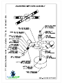
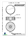
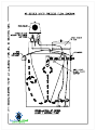
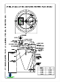
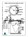
cylindrically shaped aeration tank with an
offset service access, a unique cone
shaped clarification compartment and an
outlet tee-assembly. Two fine-bubble air
diffuser assemblies with ceramic stone
diffusers and Hydro-Action® efficient rotary
air pump are combined to provide effective,
efficient, and economical aeration.
6.2: Domestic wastewater enters the
aeration compartment and is mixed
thoroughly with the already present mixed
liquor suspended solids (MLSS) activated
sludge. The injection of air through the
porous ceramic air diffusers placed near the
bottom of the aeration chamber is
responsible for this complete mixing. The
fine-bubble diffusers and the vortex area
between diffuser assemblies produce a high
magnitude of air diffusion and therein
provide ample mixing and a more than
generous quantity of dissolved oxygen to
maintain the aerobic environment even
under extreme conditions.
6.3: Hydraulic displacement causes the
mixed liquor to enter the clarification
compartment and move upward toward the
outlet tee-assembly. Due to the calm
conditions in the clarifier, suspended solids
settle to the bottom where they are remixed
with the Mixed Liquor Suspended Solids
(MLSS) for additional biological treatment.
The remaining clarified effluent leaves the
plant via the outlet tee assembly and
discharge line.
SECTION 6.0: Process Description
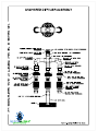
6.4: The AP Series ATUs are operated by
the OPS®. The OPS® integrates the
electrical controls, visible and audible
alarms and air pump in a protective
polyethylene enclosure. The OPS® can be
either platform mounted on the plant or
remotely located. These features plus; the
offset access, flexible air hose, and
anchored diffuser assemblies make the
plant extremely reliable and easy to service.
An optional visible and audible alarm may
be added to remotely locate to an area of
your choice.
6.1: The Hydro-Action® AP Series
individual wastewater treatment plant is a
self-contained, extended aeration, aerobic
treatment facility utilizing the activated
sludge process. The plant consists of a
6.5: The technology used in the HydroAction® plant allows it to produce excellent
effluent quality, which thereby meets all
ANSI\NSF International Standard 40 class I
and the Environmental Protection Agency’s
Aeration Pump Choices by Model
AP 500--(1) ¼ HP Rotary or (1) 100 Linear
AP 600--(1) ¼ HP Rotary or (1) 120 Linear
AP 750--(1) ¼ HP Rotary or (1) 150 Linear
AP 1000(1) 3/4 HP Rotary or (2) 100 Linear
AP 1500(1) 3/4 HP Rotary or (2) 120 Linear
requirements of a secondary treatment
process. NSF requires that a Class I plant
shall be shown to meet EPA secondary
treatment guidelines for CBOD5, TSS, and
pH. The Hydro-Action® AP Series ATUs
satisfy all these requirements.
SECTION 7.0: Safety
7.1: Safety is an important issue in our
business since we deal with one of the more
potentially health hazardous materials
known: raw sewage. Domestic wastewater
carries in it members of a specialized group
of life known as microorganisms. Such
microorganisms are bacteria, viruses, algae,
actinomycetes, protozoa, fungi, rotifers,
crustaceans, and other members of both the
plant and animal worlds. The function of a
wastewater treatment plant is to treat the
water to a degree that the effluent is
relatively free of pathogenic bacteria and
nuisance microorganisms. Until the
wastewater entering the plant has had
sufficient time for treatment and disinfection,
it may contain any number of the harmful
organisms that cause disease.
7.2: As raw wastewater may and usually
does contain some level of unsafe
microorganisms, proper respect and care
must be given to safety. When coming into
contact with raw sewage, do not fear the
contact, but do take proper precautions to
avoid potential danger.
7.3: Follow these simple safety precautions
whenever exposed to wastewater:
• Wear disposable rubber gloves when
handling wastewater contaminated items
or chlorine tablets.
• Always wash with soap and water after
handling any contaminated item. The use
of good bactericide soap is strongly
recommended.
• Always dispose of scum, rags, trash,
debris, or soiled material in a proper
waste container.
• If a wastewater spill or leak occurs in a
yard, flush area with plenty of clean
water and disinfect. If a spill or leak
occurs in the house, clean with a dilute
solution of bleach.
• Treated effluent from a Hydro- Action® or
other treatment unit may still contain
harmful microorganisms. Careful attention
must be used when dealing with any form
of wastewater or effluent.
• If an illness or disease is suspected to
have come from exposure to sewage,
get proper medical attention immediately.
When proper treatment is given the
remedy and cure will be rapid and less of
a problem. There are some serious
diseases that could be transmitted by
contact with raw sewage, take the proper
precautions and be safe!
• Report all accidents relating to sewage
exposure to the proper supervisory
personnel.
Appendix 1: OPS Explanation
50-11 Series OPS® Wastewater Plant Control
This OPS® provides total control of the aerobic unit including air pump and alarms. Other
features include separate disconnect switch (which cuts off power to all electrical components)
with an optional lockout feature. It requires a single circuit 120 volt / 20 amp feed.
Typical Applications Include:
• Direct Discharge
• Gravity Flow to Gravel Drain Fields
• Gravity Flow to Leaching Chambers or any disposal method where a pump is not required.
Equipment Included:
1 – Hydro-Action® Air Pump
1 – Polyethylene OPS® Base & Enclosure
1 – Electrical Control
Small Components Include:
Wiring harnesses, electrical connectors, liquid tight compression fittings, air tubing, shraeder
valve, audible alarm, visual alarm, and various other components which provide for integration
of the OPS®.
50-20 Series OPS®
Wastewater Plant / Pump Tank Control
This OPS® provides total control of the aerobic unit and pump tank including air pump, water
pump and alarms. Other features include two-branch circuit breakers, separate disconnect
switch (which cuts off power to all electrical components) with an optional lockout feature. It
requires a single circuit 120 volt / 30 amp feed.
Typical Applications Include:
• Spray Irrigation
• Pumping to Gravel Drain Fields
• Pumping to Low Pressure Dosing Systems
• Pumping to Leaching Chambers or any disposal method requiring a pump where timed dosing
is not required.
Equipment Included:
1 – Hydro-Action® Air Pump
1 – Polyethylene OPS® Base & Enclosure
1 – Electrical Control
Floats Switches Required:
1 – Water Pump On/Off Float
1 – Pump Tank High Level Alarm Float
Small Components Include:
Wiring harnesses, electrical connectors, liquid tight compression fittings, air tubing, shraeder
valve, audible alarm, visual alarm, and various other components which provide for integration
of the OPS®.
50-30 Series OPS®
Wastewater Plant / Pump Tank Control w/ 24 HR Timer
This OPS® provides total control of the aerobic unit and pump tank including air pump, water
pump and alarms. Other features include two-branch circuit breakers, separate disconnect
switch (which cuts off power to all electrical components) with an optional lockout feature and a
24 hr. timer. It requires a single circuit 120 volt / 30 amp feed.
Typical Applications Include:
• Spray Irrigation
• Pumping to Gravel Drain Fields
• Pumping to Low Pressure Dosing Systems
• Pumping to Leaching Chambers or any disposal method requiring a pump where 24 hr. – 15
minute increment timed dosing is required.
Equipment Included:
1 – Hydro-Action® Air Pump
1 – Polyethylene OPS® Base & Enclosure
1 – Electrical Control w/ 24 hr. – 15 min. Timer
Floats Switches Required:
1 – Water Pump On/Off Float
1 – Pump Tank High Level Alarm Float
Optional Float Switch:
1 – Pump Tank Timer Override Float
Small Components Include:
Wiring harnesses, electrical connectors, liquid tight compression fittings, air tubing, shraeder
valve, audible alarm, visual alarm, and various other components which provide for integration
of the OPS®.
50-32 Series OPS®
Wastewater Plant / Pump Tank Control w/ Micro-dose Timer / For Use w/ Hydro-action
Turtledrip.
This OPS® provides total control of the aerobic unit and pump tank including air pump, water
pump and alarms. Other features include high-level override, two-branch circuit breakers,
separate disconnect switch (which cuts off power to all electrical components) with an optional
lockout feature with a fully adjustable repeat cycle (micro-dosing) timer. It requires a single
circuit 120 volt / 30 amp feed.
Typical Applications Include:
• Drip Irrigation
• Pumping to Gravel Drain Fields
• Pumping to Low Pressure Dosing Systems
• Pumping to Leaching Chambers or any disposal method requiring a pump where micro-dosing
is desired with single float high level override / high level alarm.
Equipment Included:
1 – Hydro-Action® Air Pump
1 – Polyethylene OPS® Base & Enclosure
1 – Electrical Control w/ Micro-dosing Timer
Floats Switches Required:
1 – Water Pump On/Off Float
1 – Pump Tank High Level Alarm Float/Timer Override Float
Small Components Include:
Wiring harnesses, electrical connectors, liquid tight compression fittings, air tubing, shraeder
valve, audible alarm, visual alarm, and various other components which provide for integration
of the OPS®.
PART NO. 70 - 298 G378PL (REV-C)
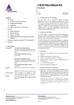
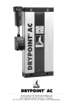
RV03-RV05 SERIES OILLESS
COMPRESSORS
OPERATION & MAINTENANCE MANUAL
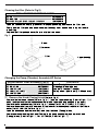
Model #RV03 Shown with
Rear Motor Fan
Model #RV03
Thank you for purchasing this Gast product. It is manufactured to the highest standards
using quality materials. Please follow all recommended maintenance, operational
and safety instructions and you will receive years of trouble free service.
IMPORTANT: PLEASE READ THIS MANUAL AND SAVE FOR FUTURE REFERENCE
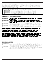
General information
• Standard Rebuild Clearances: Top: .002”
Ends: .0015” - .005”
• Model numbers ending in “X” have automatic thermal
protectors which protect the motor by shutting the motor
off if it overheats. The motor will automatically restart
once the motor has cooled.
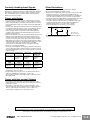
Product Use Criteria:
• Pump only clean, dry air.
• Operate at 32ºF - 104ºF (0ºC - 40ºC).
• Protect unit from dirt & moisture.
• Do not pump flammable or explosive gases or
use in an atmosphere that contains such gases.
• Protect all surrounding items from exhaust air . This
exhaust air can become very hot.
• Corrosive gases and particulate material will
damage unit. Water vapor, oil-based contaminants
or other liquids must be filtered out.
• Consult your Gast Distributor before using at high
altitudes.
• Oil-Less rotary-vanes require NO lubrication.
• Sealed bearings are grease packed.
• Use of petroleum or hydrocarbon products will
reduce carbon-vane service life.
ISO 9001 & 14001 CERTIFIED
www.gastmfg.com
®Registered Trademark/™Trademark of Gast Manu facturing Inc., Copyright © 2001 Gast Manufacturing Inc. All Rights Reserved.
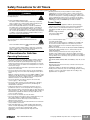
Your safety and the safety of others
is extremely important.
We have provided many important safety messages
in this manual and on your product. Always read
and obey all safety messages.
This is the safety alert symbol. This symbol
alerts you to hazards that can kill or hurt you and
others. The safety alert symbol and the words
“DANGER” and “WARNING” will precede all safety
messages. These words mean:
DANGER
You will be killed or seriously injured if you don’t
follow instructions.
WARNING
You can be killed or seriously injured if you don’t
follow instructions.
All safety messages will identify the hazard, tell you
how to reduce the chance of injury, and tell you
what can happen if the safety instructions are not
followed.
INSTALLATION
WARNING
c
Electrical Shock Hazard
Plumbing
Remove plugs from the IN and OUT ports. Connect
with pipe and fittings that are the same size or larger
than the product’s threaded ports. Install relief valves
and gauges at inlet or outlet, or both, to monitor
performance. Check valves are required to prevent
back streaming through the pump.
Accessories
The product’s intake and exhaust filters will provide
adequate filtration in most applications. Consult your
Gast representative for additional filter
recommendations.
Motor Control
It is your responsibility to contact a qualified
electrician and assure that the electrical installation is
adequate and in conformance with all national and local
codes and ordinances.
Determine the correct overload setting required to
protect the motor (see motor starter manufacturer ’s
recommendations). Select fuses, motor protective
switches or thermal protective switches to provide
protection. Fuses act as short circuit protection for the
motor, not as protection against overload. Incoming line
fuses help to withstand the motor ’s starting current.
Motor starters with thermal magnetic overload or circuit
breakers protect motor from overload or reduced
voltage conditions.
The wiring diagram attached to the product provides
required electrical information. Check that power
source is correct to properly operate the dual-voltage
motor.
OPERATION
WARNING
Injury Hazard
Disconnect electrical power at the circuit breaker
or fuse box before installing this product.
Product surfaces become very hot during operation,
allow product surfaces to cool before handling.
Install this product where it will not come into
contact with water or other liquids.
Air stream from product may contain solid or liquid
material that can result in eye or skin damage,
wear proper eye protection.
Install this product where it will be weather
protected.
Electrically ground this product.
Failure to follow these instructions can result in
death, fire or electrical shock.
Correct installation is your responsibility. Make sure
you have the proper installation conditions and that
installation clearances do not block air flow .
Blocking air flow over the product in any way can
cause the product to overheat.
Mounting
This product can be installed in any orientation.
Mounting the product to a stable, rigid operating surface
and using shock mounts will reduce noise and vibration.
Failure to follow these instructions can result in
burns, eye injury or other serious injury.
It is your responsibility to operate this product at
recommended pressures or vacuum duties and
room ambient temperatures.
Model numbers ending in “X” have automatic
thermal protectors which protect the motor by
shutting the motor off if it overheats. The motor will
automatically restart once the motor has cooled.
Start Up
If motor fails to start or slows down significantly under
load, shut off and disconnect from power supply. Check
that the voltage is correct for motor and that motor is
turning in the proper direction. Vane life will be
drastically reduced if motor is not operating properly .
Vanes can break or be damaged if motor/pump runs in
the wrong direction.
Flushing
MAINTENANCE
WARNING
c
Electrical Shock Hazard
Disconnect electrical power supply cord before
performing maintenance on this product.
If product is hard wired into system, disconnect
electrical power at the circuit breaker or fuse box
before performing maintenance on this product.
Failure to follow these instructions can result in
death, fire or electrical shock.
WARNING
Injury Hazard
Product surfaces become very hot during operation,
allow product surfaces to cool before handling.
Air stream from product may contain solid or liquid
material that can result in eye or skin damage,
wear proper eye protection.
Flush this product in a well ventilated area.
Failure to follow these instructions can result in
burns, eye injury or other serious injury.
It is your responsibility to:
• Regularly inspect and make necessary repairs to
product in order to maintain proper operation.
• Make sure that pressure and vacuum is released
from product before starting maintenance.
Check intake and exhaust filters after first six months of
operation. Clean filters and determine how frequently
filters should be checked during future operation. This
one procedure will help to assure the product’ s
performance and service life.
General Maintenance
1. Remove end cap and filters. Inspect filters for
2.
3.
4.
5.
6.
7.
8.
rips,tears, cuts, brittleness and excessive foreign
material.
Clean filters if in good condition with
compressed air. Re-inspect for wear conditions.
Set filters aside.
Check both internal and external filter felts (#8 and
#11 on exploded view) for foreign material. If felts
are dirty or worn, replace with new felts.
Check condition of O-ring on internal filter . It should
be soft and flexible. Replace if it is not.
Remove and inspect muffler box. Clean box. Set
box aside. (Not all models have a muf fler box.)
Check gasket for cracks or tears. Install new gasket
if any cracks or tears appear. Replace gasket.
Reinstall muffler box. Torque bolts to 90-120 in. lb.
Reinstall filters or install new filters if required.
Reinstall end cap finger tight.
Flushing this product to remove excessive dirt, foreign
particles, moisture or oil that occurs in the operating
environment will help to maintain proper vane
performance. There are 2 options for this operation.
If Option 1 does not remedy your problem, go on to
Option 2.
Use only Gast AH255B Flushing Solvent or other
non-petroleum based flushing solvent. Do Not use
kerosene or ANY other combustible solvents to
flush product.
Option 1
You will need 2 pipe nipples at least 4 inches long with
appropriate thread size for the unit involved. No nipples
are needed if the unit does not have a muf fler box.
1. Remove filter and muffler cap (#9).
2. Remove 5 bolts. Use a small hammer to tap on
muffler box to remove it. Attach pipe nipples
where muffler caps were removed.
3. Start product and add flushing solvent to the inlet
port. If using liquid solvent, pour several
tablespoons directly into the inlet port. If using Gast
AH255B, spray solvent for 5-10 seconds into inlet
port. Place towel over exhaust port to clean up
solvent.
4. Plug inlet port for 20-30 seconds. Listen for
changes in the sound of the pump. If pump sounds
smooth, go to next step. If pump does not sound
like it is running smoothly, installing a Service Kit wil
be required (See Service).
5. Release vacuum.
6. Repeat steps 3-5 three or four times.
If Option 1 is not successful, remove the end plate and
examine.
Option 2
1. Remove six end plate bolts. (See exploded view .)
2. Use a small hammer to carefully tap on end plate to
remove. Do not use a screwdriver to pry of f.
3. Check that vanes are moving freely in and out of
vane slots. Replace vanes if more than 50% of the
vane extends past the vane slot.
4. Remove vanes and clean both sides with fine emery
cloth. Clean end-plate with fine emery cloth.
5. Flush vanes with AH255B solvent and remove all
solvent from vanes.
6. Flush body, rotor and end plate with AH255B
solvent, then remove all solvent from each part.
7. Check body, rotor and end plate for scoring. If each
part is clean and shows no signs of scoring,
re-install parts. If scoring appears,
send unit to factory or replace with new part(s).
8. Insert vanes, checking that the bevel edges are in
the correct direction.
9. Replace end plate. Torque bolts to 90-120 in. lb.
10. Check gasket for damage.
11. Reinstall muffler box. Torque bolts to 90-120 in. lb.
Check that all external accessories such as relief
valves and gauges are attached to cover and are
not damaged before re-operating product.
SHUTDOWN PROCEDURES
It is your responsibility to follow proper shutdown
procedures to prevent product damage.
NEVER ADD OIL TO THIS OIL-LESS PUMP.
1. Disconnect plumbing.
2. Operate product for at least five minutes without
plumbing.
3. Run at maximum vacuum for 10-15 minutes.
4. Repeat step 2.
5. Disconnect power supply.
6. Plug open ports to prevent dirt or other
contaminants from entering product.
SERVICE KIT INSTALLATION
WARNING
c
Electrical Shock Hazard
Disconnect electrical power supply cord before
installing Service Kit.
If product is hard wired into system, disconnect
electrical power at the circuit breaker or fuse box
before installing Service Kit.
Vent all air lines to release pressure or vacuum.
Failure to follow these instructions can result in
death, fire or electrical shock.
Gast will NOT guarantee field-rebuilt product
performance. For performance guarantee, the
product must be returned to a Gast-authorized
facility.
Service Kit contents vary. Most contain vanes, gaskets
and filter parts.
1.
2.
3.
4.
5.
6.
7.
Remove filter/muffler parts from front of muf fler box.
Remove the 5 muffler box bolts.
Use a small hammer to tap on box to remove. Do
not use a screwdriver.
Remove the 6 end plate bolts.
Remove end plate. Check direction of bevel edges
of vanes then remove vanes.
Clean body and rotor slots with AH255B or
equivalent flushing solvent. Hand turn the rotor to
make sure it rotates freely. Any unusual grinding or
scraping sound could indicate worn bearings or
scored parts.
Check end plate, rotor and body for scoring.
Severe scoring or worn bearings will require
service at a Gast-authorized facility.
DO NOT remove rotor or motor bolts.
8.
Insert vanes, checking that the bevel edges are in
the correct direction. See diagram below .
9. Replace end plate. Torque bolts to 90-120 in. lb.
10. Check gasket for damage.
11. Reinstall muffler box. Torque bolts to 90-120 in. lb.
Check that all external accessories such as relief
valves and gauges are attached and are not damaged
before re-operating product.
The vanes need to be flush with the curvature of
the rotor when installing.
END CAP FILTER
10
QTY
1
1
FOOT SUPPORT KIT
FELT SUPPORT
FELT FILTER
SCREEN CAP
ROTOR
TOLERANCE RING
SERVICE KIT
13
14*
15
16
17
RV03-101
K882
AF105
AH775B
AJ571
B344A
B347
AC136
B343B
AK526
AK510
AK524
AK473
AK519
AK521
AK501
AK502B
AH850A
AK504
RV05-101
K882
AF105
AH775B
AJ571
B344A
B347
AC136
B343B
AK526
AK510
AK524
AK473
AK519
AK521
AK501
AK502B
AH850A
AK500
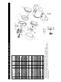
* Denotes parts included in the Service Kit. Parts listed are for stock models.
** No Service Kit available, order parts separately . For specific OEM models, please
consult the factory. When corresponding or ordering parts, please give complete model
and serial numbers.
1
1
2
1
1
FILTER / MUFFLER
12
1
2
2
2
2
1
1
1
1
4
1
11
ASSEMBLY
END CAP
FELT
*
8
9
O-RING
*
MUFFLER BOX
7
6
GASKET
END PLATE
*
4
5
SHROUD
VANE
3
*
BODY
1
2
DESCRIPTION
REF
EXPLODED PRODUCT VIEW, PARTS & ORDERING INFORMATION
Intake Filter
Assembly
WARRANTY
Gast finished products, when properly installed and operated under normal conditions of use, are warranted by Gast to
be free from defects in material and workmanship for a period of twenty four (24) months from the date of purchase
from Gast or an authorized Gast Representative or Distributor . In order to obtain performance under this warranty , the
buyer must promptly (in no event later than thirty (30) days after discovery of the defect) give written notice of the defect
to Gast Manufacturing Incorporated, PO Box 97, Benton Harbor Michigan USA 49023-0097 or an authorized Service
Center (unless specifically agreed upon in writing signed by both parties or specified in writing as part of a Gast OEM
Quotation). Buyer is responsible for freight charges both to and from Gast in all cases.
This warranty does not apply to electric motors, electrical controls, and gasoline engines not supplied by Gast. Gast’ s
warranties also do not extend to any goods or parts which have been subjected to misuse, lack of maintenance,
neglect, damage by accident or transit damage.
THIS EXPRESS WARRANTY EXCLUDES ALL OTHER WARRANTIES OR REPRESENTATIONS EXPRESSED OR
IMPLIED BY ANY LITERATURE, DATA, OR PERSON. GAST’S MAXIMUM LIABILITY UNDER THIS EXCLUSIVE
REMEDY SHALL NEVER EXCEED THE COST OF THE SUBJECT PRODUCT AND GAST RESERVES THE RIGHT,
AT ITS SOLE DISCRETION, TO REFUND THE PURCHASE PRICE IN LIEU OF REPAIR OR REPLACEMENT.
GAST WILL NOT BE RESPONSIBLE OR LIABLE FOR INDIRECT OR CONSEQUENTIAL DAMAGES OF ANY KIND,
however arising, including but not limited to those for use of any products, loss of time, inconvenience, lost profit, labor
charges, or other incidental or consequential damages with respect to persons, business, or property , whether as a
result of breach of warranty, negligence or otherwise. Notwithstanding any other provision of this warranty , BUYER’S
REMEDY AGAINST GAST FOR GOODS SUPPLIED OR FOR NON-DELIVERED GOODS OR F AILURE TO FURNISH
GOODS, WHETHER OR NOT BASED ON NEGLIGENCE, STRICT LIABILITY OR BREACH OF EXPRESS OR
IMPLIED WARRANTY IS LIMITED SOLELY, AT GAST’S OPTION, TO REPLACEMENT OF OR CURE OF SUCH
NONCONFORMING OR NON-DELIVERED GOODS OR RETURN OF THE PURCHASE PRICE FOR SUCH GOODS
AND IN NO EVENT SHALL EXCEED THE PRICE OR CHARGE FOR SUCH GOODS. GAST EXPRESSLY
DISCLAIMS ANY WARRANTY OF MERCHANTABILITY OR FITNESS FOR A PARTICULAR USE OR PURPOSE WITH
RESPECT TO THE GOODS SOLD. THERE ARE NO WARRANTIES WHICH EXTEND BEYOND THE DESCRIPTIONS
SET FORTH IN THIS WARRANTY, notwithstanding any knowledge of Gast regarding the use or uses intended to be
made of goods, proposed changes or additions to goods, or any assistance or suggestions that may have been made
by Gast personnel.
Unauthorized extensions of warranties by the customer shall remain the customer ’s responsibility.
CUSTOMER IS RESPONSIBLE FOR DETERMINING THE SUITABILITY OF GAST PRODUCTS FOR CUSTOMER’S
USE OR RESALE, OR FOR INCORPORATING THEM INTO OBJECTS OR APPLICATIONS WHICH CUSTOMER
DESIGNS, ASSEMBLES, CONSTRUCTS OR MANUFACTURES.
This warranty can be modified only by authorized Gast personnel by signing a specific, written description of any
modifications.
MAINTENANCE RECORD
DATE
PROCEDURE PERFORMED
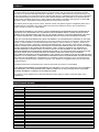
TROUBLESHOOTING CHART
Low
High
Vacuum
Pressure
l
l
Vacuum Pressure
At pump
At pump
l
At pump
l
l
Pump
Motor
Reason and remedy
Overheat
Overload
for problem.
l
l
Filter dirty.
Clean or replace.
l
l
Muffler dirty.
Clean or replace.
l
l
Vacuum line collapsed.
Repair or replace.
l
l
Relief valve set too high.
Inspect and adjust.
Relief valve set too low.
Inspect and adjust.
l
l
l
l
l
l
Vanes sticking.
Clean or replace.
l
l
Vanes worn.
Replace.
l
l
At pump At pump
l
l
Plugged vacuum/pressure line.
Inspect and repair.
l
l
l
Foreign material- in pump.
Inspect and clean.
l
l
l
Motor not wired correctly.
Check wiring diagram and line voltage.
We have Gast Certified Service Centers throughout the world. For the most up-to-date
listing, contact one of our sales offices below:
World Headquarters
P.O. Box 97
2550 Meadowbrook Rd.
Benton Harbor, MI
49023-0097
Ph: 269/926-6171
FAX: 269/925-8288
www.gastmfg.com
Gast Hong Kong
Unit 12, 21/F, Block B
New Trade Plaza
6, On Ping Street, Shatin
N. T. Hong Kong
Ph: (852) 2690 1008
Fax: (852) 2690 1012
www.gasthk.com
ISO 9001 & 14001 CERTIFIED
www.gastmfg.com
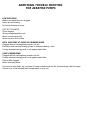
ADDITIONAL TROUBLE SHOOTING
FOR AERATION PUMPS
LOW PRESSURE
Make sure intake filter isn’t clogged
Vanes are not sticking
No foreign material in pump
UNIT NOT RUNNING
Check breaker
Wrong voltage applied to unit
Motor is wired incorrectly
Motor has dust & dirt inside
HIGH PRESSURE AT PUMP OR GRINDING NOISE
Plugged diffuser causing back pressure on unit
Excessive heat causing bearing grease to dissipate causing noise
Foreign material causing parts to rub against each other .
PUMP OVERHEATING
Plugged diffuser causing back pressure on unit
Foreign material causing parts to rub against each other .
Filter/muffler clogged
Motor incorrectly wired
Unit must be kept clean, dry, and free of foreign material such as dirt, moisture,bugs, and hot temps.
Failure to do so will shorted the life expectance of your unit.
INSTRUCTION MANUAL
OPERATION & MAINTENANCE
TECHNICAL MANUAL
HIBLOW SERIES COMPRESSORS
MODELS
01 ISO
40
an
HI
BL
1
900
ISO 1
O W Jap
1 2 3 4 1
DANGER: 5 3 WARNING: 5 3 CAUTION: - 3 GENERAL INFORMATION
DANGER: # CAUTION: # 2 "
CAUTION: 6 7,℃&*,7°8) 8 CAUTION: ! INSTALLATION
WARNING: " ! &'() CAUTION: # *
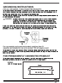
GROUNDING INSTRUCTIONS
FOR ALL GROUNDED, CORD-CONNECTED PRODUCTS
% " DANGER: % %
! "
# $ "
.
.
/
!
.
0
For a grounded, cord-connected product rated less than 15
amperes and intended for use on a nominal 120 volt supply circuit.
*+, - FOR PERMANENTLY CONNECTED PRODUCT
" &
)
WIRING
*+,9 6! 2 #
/
-
. : . 5
(
9
2;4 &<)
01 ISO
40
an
HI
BL
1
900
ISO 1
/ 5 0 -
O W Jap
+
9 . :
: ) : 1' .
+ ) *. . .
3 %55 ") ; %4 3+< 3 6 * " *
$
) * "
) ' +
+3
+ , -) ' " * " -) - . ' " ( ) * ) " "
&
' " ! " #"
$ %
" . 1' " :
( * ' " - &
"
' *
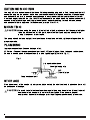
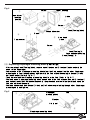
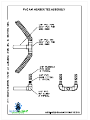
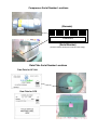
・After the Diaphragm mounting block have been installed, replace with the new Head (Casing)
block, reattaching the L-tube, and reinstall the 4 screws holding the Head (Casing) on. (Refer to
Fig.4-③or⑤)
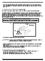
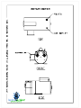
〔3〕Replacement of Safety Screw (Refer to Fig.6)
SP Switch (For HP-60/HP-80/HP-100/HP-100LL/HP-120/HP-120LL/HP-150/HP-200 Series)
The body of the switch is set on the upper part of the Rod. If the Diaphragm is damaged or unit is
dropped, the unusual movement of the Rod will cause the upper part of the Rod to touch the Lshaped lever, contacting the spring terminal, breaking the safety screw. This turns the power off,
stopping the pump automatically. This is a built in safety device to prevent any further damage to the
pump. To replace SP Screw:
REPLACEMENT SAFETY SCREW PART#
HP-60/HP-80/HP-100/HP-100LL/HP-120/HP-120LL/HP-150/HP-200 PASPSW0200
Fig. 6
Beam
Safety screw
Nut Spring
electrode
L-shaped lever
・First remove the pump plug from the electrical outlet.
WARNING: All power must be disconnected or deenergized before servicing unit. If hazard is
ignored personal injury or property damage is possible.
・Dispose of broken screw. Be sure all debris is removed (may be necessary to turn pump upside
down) from unit.
・Fasten screw with plastic nut. The screw is designed so that the nut will turn freely when it is
properly fastened, stop tightening when this happens.
〔4〕Reinstall the Upper housing (Refer to Fig.4)
・Reinstall the 4 screws holding the Frame cover on. (For HP-100/120, Refer to Fig.4- ④)
・Reinstall the Sound absorber (except for HP-40, HP-100LL, HP-120LL).
・Reinstall the Upper housing and tighten corner screws. (Refer to Fig.4- ①)
7
" *
. / " "" ". "
& "
/ " ) " ")
) ..
0
. + "
) * "
$ 23 $ 2!) . "
( *
.4567856"
-. * " () ') ) ) "
*
0
0
&'
3. "
*
$
') ,
. ( . .
. ) " ( "
. 3 "
*
"
3. * " "
. 3
6 * $. & " "
*
. + "
) " "
$
! . "
"
&" ' ) " . ) "" .
$
) "
.) 3
6 *
$.
=
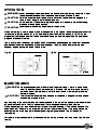
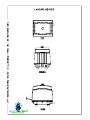
Cleaning the filter (Refer to Fig.3)
REPLACEMENT FILTERPAD PART#
&%0&&&&'&
$%&
.&%0&&&&&
$%-&+$%.&
$%'&&+$%'&&((+$%')&+$%')&((+$%'/&+$%)&&
')&%0)&&'&
・ ! ・3!" ! ! " " !! !!
・! ! #
Fig. 3
#
! !
Changing the Pump (Chamber) Assembly-HP Series
REPLACEMENT PUMP ASSEMBLY PART#
$%&
$%-&+$%.&
$%'&&+$%')&
$%'&&((+$%')&((
$%'/&+$%)&&
&%,&&&&1&
.&%,&&&&'
')&%,)&&''
')&%,)&&)'
)&&%,)&&''
CONTENTS
$ , !
2 !
$ ! + #" + ! $%-& 〔1〕Remove the Head (Casing) block ・ ① ② ! !" " ・ #
② $%& $%'&&(( $%')&((
・ !! *
! $%'&&+')& ④
・ (
$ , !
・ $ , $
, ! ③ $%'&&+')& ⑤
/
Fig. 4
①
! ②
③
④
⑤
〔2〕Replacing Diaphragm mounting block &" %)
・" # " $ ! " %
・& " ' " &# '
" ( & $ !
% &" %)①
・* ' " &% &" %) ②
・& ' " & $ ! # & " & %
・& $ ! & '
%
'
&
+
! ②
' HI
BL
1
900
01 ISO
40
an
①
ISO 1
Fig. 5
O W Jap
,
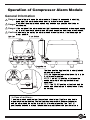
Operation of Compressor Alarm Module
General Information
Danger: Do not attempt to open the alarm module. If the unit is connected to electricity,
opening of the alarm module can result in a risk of electric shock.
Danger: Service of the alarm module should only be done by a qualified electrician or
serviceman.
Danger: If the outside of the alarm module or light lens becomes cracked or damaged, unplug
or shut-off the electric power immediately and contact an electrician or serviceman.
Caution: Do not carry the unit by the alarm module or electrical cord. It could damage the
alarm module.
Light Lens
Alarm Module
Toggle Switch
The three position toggle switch is clearly labeled
on the alarm module.
RUN : During normal operation the switch is in the
"RUN" or center position.
MUTE : The "MUTE" position will silence the
audible alarm while leaving the visual alarm
operational.
TEST : The "TEST" position will activate both the
audible and visual alarms to check to see if they
are working.
In Case of an Alarm :
01 ISO
40
an
HI
BL
1
900
ISO 1
The alarm module audible alarm (buzzer) and visual alarm (light) are intended to
signal a system malfunction. Contact your service provider whenever you hear or
see the alarm when the switch is in the "RUN" or center position. The "MUTE"
position can be used to silence the audible alarm until the service provider arrives.
O W Jap
8
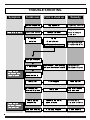
TROUBLE SHOOTING
Symptom
Possible cause
Point to check up
Remedy
" 蘆" "
蘆 %
!
# $ # # 3
YOUR WARRANTY
6 6 7&89 6* - 7'(9 6 :" -* &'(( ) " + " , :" .+&/0* % 6 *
6;
< *
)
* 6;
< 6 *
6 = = *
%;
6 2 6;
* 6 * ) 6 6 *
:> ;
*
6 ;
<
*
)
> 6 *
AUTHORIZED SERVICE CENTER
&'(( ) * " + " ,- .+&/0
)1 /'.23..24(.' 5 /'.23..24&0'
01 ISO
40
an
HI
BL
1
900
ISO 1
http://www.hiblow-usa.com
O W Jap
&(
an
ISO 1
HI
BL
9001
01 ISO
40
O W Jap
http://www.takatsuki.co.jp
!!" "# $%" &'%( http://www.hiblow-usa.com
Printed in Japan KA04000840
2JU.0802.500犧
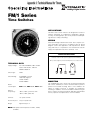
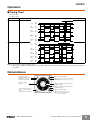
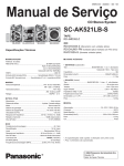
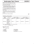
FM/1 Series
Time Switches
APPLICATIONS
The FM/1 series of time switches are designed for control of
heating, ventilating, air conditioning, refrigeration, lighting,
security, circulating pumps, spas or any electrical load requiring 24-hour or 7-day scheduling.
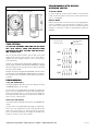
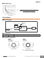
WIRING
Verify input voltage stated on back of unit. Use 1/4” quick connects and make connections in accordance with the wiring
diagram shown and applicable code requirements. When
using 24V units, it is important to use transformers that will
supply the required 24 volts AC to terminals 1 & 2.
Terminal Connections
Contacts shown in “Off” position (trippers pushed inward)
“On” position (trippers pushed outward) will close contacts 3 & 4
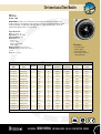
TECHNICAL DATA
Supply Voltage:
24, 120 and 240VAC, 60Hz models
Quartz: 24V AC/DC, 120 and
240VAC 50/60 Hz
Switch Type:
SPDT
Switch Rating:
21A/250VAC resistive
1350 watt tungsten
1HP @ 125VAC
2HP @ 240VAC
Power
Consumption:
Ambient
Temp. Range:
24V: 0.1VA; 120V: 0.5VA; 240V: 1.0VA
–40°F to 180°F, synchronous units
–20°F to 140°F, quartz units
Terminals:
1/4” spade terminals
Reserve Carryover:
7 days for quartz units
Weight:
Approximately 3 oz.
NOTE: 24V quartz unit will operate on 6VDC, 12VDC,
or 24VDC
M
5
4
3
NC
NO
COM
2
1
INPUT
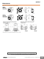
MOUNTING
The standard FM/1 units can be flush mounted (mounting kit
with screws available) or surface mounted inside a panel. A
printed circuit board mounting base is also available. An
indoor or outdoor enclosure is available for stand-alone
mounting. In addition, unit is also available in DIN housing for
flush or surface mounting (see MIL72, Digi 20 or Digi 42 data
sheets). Optional clear plastic dust cover is available.
Dimensions
FM/1 synchronous/quartz
PROGRAMMING WITH MANUAL
OVERRIDE SWITCH
AUTOMATIC MODE
In order to operate the time switch module in the automatic
mode, the manual switch must be in the center position (automatic) - see diagram.
MANUAL MODE
With the manual switch selector lever the selected programs
can be overridden. In the lower position, marked “O”, terminals 3 and 5 are permanently closed. In the upper position,
marked “I”, terminals 3 and 4 are permanently closed (see
diagram).
Override Mode
TIME SETTING
3-way manual
override switch
I = permanent ON
= automatic
0 = permanent OFF
TO SET THE CURRENT TIME (AND DAY OF WEEK
ON 7 DAY UNITS), TURN THE MINUTE HAND
CLOCKWISE. DO NOT SET THE TIME BY ROTATING “OUTER” DIAL.
Turn the minute hand clockwise until the day of the week
(7-day timer) and the time of day on the outer dial is
aligned with the triangle marker on the inner dial (two
o'clock position).
Example for 7-day program dial Monday 10:30 AM. Turn the
minute hand clockwise until Monday 10:30 AM is aligned
with the triangle on the inner dial. The hour and minute hand
will show exactly 10:30.
Example for 24-hour program dial 10:30 AM. Turn the minute
hand clockwise until 10:30 AM is aligned with the triangle on
the inner dial. The hour and the minute dial will show exactly 10:30.
PROGRAMMING
7-Day (SW, QRW Models)
The weekly program dial reflects the seven days of the week
and AM/PM imprints for each day.
The time switch is programmed by pushing the captive trippers to the outer ring position for the entire period that the
load is to be turned “ON”, i.e., two hours for each tripper on
the 7-Day dial. When the tripper is pushed to the inside, the
switch is in the “OFF” position.
24-Hour (ST, QRT Models)
The 24-Hour dial has quarter-hour divisions and AM/PM indications.
The time switch is programmed by pushing the captive trippers to the outer ring position for the entire period that the
load is to be turned “ON”, i.e., fifteen minutes for each tripper on the 24-Hour dial. When the tripper is pushed to the
inside, the switch is in the “OFF” position.
Intermatic Incorporated • Spring Grove, IL 60081 • www.intermatic.com
300GR10020
Electromechanical Timer Modules
FM/1 Series
24 Hour, 7 Day
APPLICATION: The FM/1 series electromechanical timer modules are designed to be placed inside a
machine control panel, circuit board, or other equipment. It offers up to 21A switching designed for control
of heating, ventilating, air conditioning, refrigeration, lighting, security, circulating pumps, spas or any
electrical load requiring 24-hour or 7-day scheduling.
Specifications:
Size: 2.36” x 2.36” x 1.25”
Supply Voltage: 24, 120, 240VAC
Power Consumption: 1 VA
Switch Rating: SPDT
Resistive: 21A
Tungsten: 1350W
Inductive: 1HP @ 120VAC
2HP @ 240VAC
Wiring Connections: 1/4” quick-connects
Installation: Stand Alone: With indoor or outdoor
enclosure
Panel: Surface mounting
Features:
• 21A SPDT switch
• Captive Trippers
• 1/4” quick terminals
• Noise Immune—Ideal for
robust applications
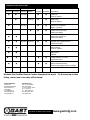
FM/1 Series Ordering Data†
Grasslin
Model
Intermatic
Model
Override
Switch
Program
Carryover
Program
On/Off Every
Minimum
On/Off Time
Switch Output
Type
Switch Output
Rating
FM/1 STuZ-120
FM1STUZ-120U
No
24 Hr.
No
15 Minutes
15 Minutes
SPDT
21A. Res.
FM/1 STuZ-24
FM1STUZ-24U
No
24 Hr.
No
15 Minutes
15 Minutes
SPDT
21A. Res.
FM/1 STuZ-240
FM1STUZ-240U
No
24 Hr.
No
15 Minutes
15 Minutes
SPDT
21A. Res.
FM/1 SWuZ-120
FM1SWUZ-120U
No
7 day
No
2 Hours
2 Hours
SPDT
21A. Res.
FM/1 SWuZ-24
FM1SWUZ-24U
No
7 day
No
2 Hours
2 Hours
SPDT
21A. Res.
FM/1 SWuZ-240
FM1SWUZ-240U
No
7 day
No
2 Hours
2 Hours
SPDT
21A. Res.
FM/1 STuZH-120
FM1STUZH-120U
Yes
24 Hr.
No
15 Minutes
15 Minutes
SPDT
21A. Res.
FM/1 STuZH-24
FM1STUZH-24U
Yes
24 Hr.
No
15 Minutes
15 Minutes
SPDT
21A. Res.
FM/1 STuZH-240
FM1STUZH-240U
Yes
24 Hr.
No
15 Minutes
15 Minutes
SPDT
21A. Res.
FM/1 SWuZH-120
FM1SWUZH-120U
Yes
7 day
No
2 Hours
2 Hours
SPDT
21A. Res.
FM/1 SWuZH-24
FM1SWUZH-24U
Yes
7 day
No
2 Hours
2 Hours
SPDT
21A. Res.
FM/1 SWuZH-240
FM1SWUZH-240U
Yes
7 day
No
2 Hours
2 Hours
SPDT
21A. Res.
FM/1 SWuZH-277
FM1SWUZH-277U
Yes
7 day
No
2 Hours
2 Hours
SPDT
21A. Res.
FM/1 QTuZH-120
FM1QTUZH-120U
Yes
24 Hr.
7 day
15 Minutes
15 Minutes
SPDT
21A. Res.
FM/1 QTuZH-24
FM1QTUZH-24U
Yes
24 Hr.
7 day
15 Minutes
15 Minutes
SPDT
21A. Res.
FM/1 QWuZH-120
FM1QWUZH-120U
Yes
7 day
2 Hr.
2 Hours
2 Hours
SPDT
21A. Res.
FM/1 QWuZH-240
FM1QWUZH-240U
Yes
7 day
2 Hr.
2 Hours
2 Hours
SPDT
21A. Res.
Available with 24V, 120V, 240V, 277VAC input
WEATHERPROOF • ENERGY CONTROLS • PROFESSIONAL LIGHTING • POOL & SPA • SURGE PROTECTION • CONSUMER
93
Solid-state Twin Timers
H3CR-F
DIN 48 × 48-mm Twin Timers
• Wide power supply ranges of 100 to 240 VAC and 48 to
125 VDC respectively.
• ON- and OFF-times can be set independently and so
combinations of long ON- or OFF-time and short OFF- or ONtime settings are possible.
• Fourteen time ranges from 0.05 s to 30 h or from 1.2 s to 300 h
depending on the model to be used.
• Models with a flicker ON start or flicker OFF start are available.
• Easy sequence checks through instantaneous outputs for a
zero set value at any time range.
• Length, when panel-mounted with a Socket, of 80 mm or less.
• 11-pin and 8-pin models are available.
Model Number Structure
■ Model Number Legend
H3CR - F @ @ - @ @
1 2
3
4
5
1. Classification
F:
Twin timers
2. Configuration
None: 11-pin socket
8:
8-pin socket
3. Twin Timer Mode
None: Flicker OFF start
N:
Flicker ON start
4. Time Range
None: 0.05 s to 30 h models
300: 1.2 s to 300 h models
5. Supply Voltage
100-240AC: 100 to 240 VAC
24AC/DC: 24 VAC/VDC
12DC:
12 VDC
48-125DC: 48 to 125 VDC
Ordering Information
■ List of Models
Operating
modes
Flicker OFF
start
Supply
voltage
100 to 240 VAC
0.05 s to 30 h models
11-pin models
H3CR-F 100-240AC
1.2 s to 300 h models
8-pin models
11-pin models
H3CR-F8 100-240AC
H3CR-F-300 100-240AC
8-pin models
H3CR-F8-300 100-240AC
24 VAC/DC
H3CR-F 24AC/DC
H3CR-F8 24AC/DC
H3CR-F-300 24AC/DC
H3CR-F8-300 24AC/DC
12 VDC
H3CR-F 12DC
H3CR-F8 12DC
H3CR-F-300 12DC
H3CR-F8-300 12DC
48 to 125 VDC
H3CR-F 48-125DC
H3CR-F8 48-125DC
H3CR-F-300 48-125DC
H3CR-F8-300 48-125DC
H3CR-FN 100-240AC
H3CR-F8N 100-240AC
H3CR-FN-300 100-240AC
H3CR-F8N-300 100-240AC
H3CR-F8N-300 24AC/DC
Flicker ON start 100 to 240 VAC
24 VAC/DC
H3CR-FN 24AC/DC
H3CR-F8N 24AC/DC
H3CR-FN-300 24AC/DC
12 VDC
H3CR-FN 12DC
H3CR-F8N 12DC
H3CR-FN-300 12DC
H3CR-F8N-300 12DC
48 to 125 VDC
H3CR-FN 48-125DC
H3CR-F8N 48-125DC
H3CR-FN-300 48-125DC
H3CR-F8N-300 48-125DC
Note: Specify both the model number and supply voltage when ordering.
Example: H3CR-F 100-240AC
Supply voltage
http://www.ia.omron.com/
(c)Copyright OMRON Corporation 2007 All Rights Reserved.
1
H3CR-F
■ Accessories (Order Separately)
Name/specifications
Models
Flush Mounting Adapter
Y92F-30
Y92F-73
Y92F-74
Mounting Track
50 cm (l) × 7.3 mm (t)
PFP-50N
1 m (l) × 7.3 mm (t)
PFP-100N
1 m (l) × 16 mm (t)
PFP-100N2
End Plate
PFP-M
Spacer
PFP-S
Protective Cover
Y92A-48B
Track Mounting/
Front Connecting Socket
Back Connecting Socket
Hold-down Clip (See note 2)
8-pin
P2CF-08
8-pin, finger safe type
P2CF-08-E
11-pin
P2CF-11
11-pin, finger safe type
P2CF-11-E
8-pin
P3G-08
8-pin, finger safe type
P3G-08 with Y92A-48G (See note 1)
11-pin
P3GA-11
11-pin, finger safe type
P3GA-11 with Y92A-48G (See note 1)
For PL08 and PL11 Sockets
Y92H-7
For PF085A Socket
Y92H-8
Note: 1. Y92A-48G is a finger safe terminal cover which is attached to the P3G-08 or P3GA-11 Socket.
2. Hold-down Clips are sold in sets of two.
Specifications
■ General
Item
H3CR-F
H3CR-F8
H3CR-FN
Operating mode
Flicker OFF start
Pin type
11-pin
Operating/Reset method
Time-limit operation/Time-limit reset or self-reset
Output type
Relay output (DPDT)
Mounting method
DIN track mounting, surface mounting, and flush mounting
Approved standards
UL508, CSA C22.2 No.14, NK, Lloyds
Conforms to EN61812-1 and IEC60664-1 (VDE0110) 4kV/2.
Output category according to EN60947-5-1.
H3CR-F8N
Flicker ON start
8-pin
11-pin
8-pin
■ Time Ranges
0.05 s to 30 h Models
Time unit
Setting
×10 s (10 sec)
s (sec)
min (min)
1.2
0.05 to 1.2
1.2 to 12
0.12 to 1.2
3
0.3 to 3
3 to 30
0.3 to 3
12
1.2 to 12
12 to 120
1.2 to 12
30
3 to 30
30 to 300
3 to 30
h (hrs)
Note: Instantaneous output is available at any time range. To obtain instantaneous output, set to below 0.
1.2 s to 300 h Models
Time unit
Setting
×10 s (10 sec)
×10 min (10 min)
h (hrs)
×10 h (10 hrs)
1.2
1.2 to 12
1.2 to 12
0.12 to 1.2
1.2 to 12
3
3 to 30
3 to 30
0.3 to 3
3 to 30
12
12 to 120
12 to 120
1.2 to 12
12 to 120
30
30 to 300
30 to 300
3 to 30
30 to 300
Note: Instantaneous output is available at any time range. To obtain instantaneous output, set to below 0.
http://www.ia.omron.com/
(c)Copyright OMRON Corporation 2007 All Rights Reserved.
2
H3CR-F
■ Ratings
Rated supply voltage (See notes 1, 2, and 3.) 100 to 240 VAC (50/60 Hz),12 VDC, 24 VAC/DC (50/60 Hz), 48 to 125 VDC
Operating voltage range
85% to 110% of rated supply voltage; 90% to 110% with 12-VDC models
Power reset
Minimum power-opening time: 0.1 s
Power consumption
100 to 240 VAC: approx. 10 VA (2.1 W) at 240 VAC
24 VAC/VDC:
approx. 2 VA (1.7 W) at 24 VAC
approx. 1 W at 24 VDC
48 to 125 VDC: approx. 1.5 W at 125 VDC
12 VDC:
approx. 1 W at 12 VDC
Control outputs
Contact output: 5 A at 250 VAC/30 VDC, resistive load (cosφ = 1)
Note: 1. A power supply with a ripple of 20% max. (single-phase power supply with full-wave rectification) can be used with each DC Model.
2. Do not use an inverter output as the power supply. Refer to Safety Precautions for All Timers for details.
3. Refer to Safety Precautions for All Timers when using the Timer together with a 2-wire AC proximity sensor.
■ Characteristics
Accuracy of operating
time
±0.2% FS max. (±0.2% FS ±10 ms max. in ranges of 1.2 and 3 s)
Setting error
±5% FS ±50 ms max.
Reset time
0.1 s max.
Reset voltage
10% max. of rated voltage
Influence of voltage
±0.2% FS max. (±0.2% FS ±10 ms max. in ranges of 1.2 and 3 s)
Influence of temperature ±1% FS max. (±1% FS ±10 ms max. in ranges of 1.2 and 3s)
Insulation resistance
100 MΩ min. (at 500 VDC)
Dielectric strength
2,000 VAC, 50/60 Hz for 1 min (between current-carrying metal parts and exposed non-current-carrying metal parts)
2,000 VAC, 50/60 Hz for 1 min (between control output terminals and operating circuit)
2,000 VAC, 50/60 Hz for 1 min (between contacts of different polarities)
1,000 VAC, 50/60 Hz for 1 min (between contacts not located next to each other)
Impulse withstand
voltage
3 kV (between power terminals) for 100 to 240 VAC, 48 to 125 VDC
1 kV for 12 VDC, 24 VAC/DC
4.5 kV (between current-carrying terminal and exposed non-current-carrying metal parts) for 100 to 240 VAC, 48 to
125 VDC
1.5 kV for 12 VDC, 24 VAC/DC
Noise immunity
±1.5 kV (between power terminals), square-wave noise by noise simulator (pulse width: 100 ns/1 μs, 1-ns rise)
±400 V for 12 VDC
Static immunity
Malfunction: 8 kV
Destruction: 15 kV
Vibration resistance
Destruction: 10 to 55 Hz with 0.75-mm single amplitude for 2 hrs each in three directions
Malfunction: 10 to 55 Hz with 0.5-mm single amplitude for 10 min each in three directions
Shock resistance
Destruction: 980 m/s2 three times each in six directions
Malfunction: 98 m/s2 three times each in six directions
Ambient temperature
Operating:
Storage:
−10°C to 55°C (with no icing)
−25°C to 65°C (with no icing)
Ambient humidity
Operating:
35% to 85%
Life expectancy
Mechanical: 20 million operations min. (under no load at 1,800 operations/h)
Electrical:
100,000 operations min. (5 A at 250 VAC, resistive load at 1,800 operations/h) (See note)
EMC
(EMI)
Emission Enclosure:
Emission AC Mains:
(EMS)
Immunity ESD:
EN61812-1
EN55011 Group 1 class A
EN55011 Group 1 class A
EN61812-1
IEC61000-4-2:
6 kV contact discharge (level 3)
8 kV air discharge (level 3)
Immunity RF-interference from AM Radio Waves:
IEC61000-4-3: 10 V/m (80 MHz to 1 GHz) (level 3)
Immunity RF-interference from Pulse-modulated Radio Waves: IEC61000-4-3: 10 V/m (900±5 MHz) (level 3)
Immunity Conducted Disturbance: IEC61000-4-6:
10 V (0.15 to 80 MHz) (level 3)
Immunity Burst:
IEC61000-4-4:
2 kV power-line (level 3)
2 kV I/O signal-line (level 4)
Immunity Surge:
IEC61000-4-5:
1 kV line to line (level 3)
2 kV line to ground (level 3)
Case color
Light Gray (Munsell 5Y7/1)
Degree of protection
IP40 (panel surface)
Weight
Approx. 100 g
Note: Refer to the Life-test Curve.
http://www.ia.omron.com/
(c)Copyright OMRON Corporation 2007 All Rights Reserved.
3
H3CR-F
■ Life-test Curve
Switching operations (x 103)
10,000
5,000
1,000
500
Reference: A maximum current of 0.15 A can be switched at 125 VDC (cosφ = 1)
and a maximum current of 0.1 A can be switched if L/R is 7 ms. In
both cases, a life of 100,000 operations can be expected.
The minimum applicable load is 10 mA at 5 VDC (failure level: P).
30 VDC L/R = 7 ms
250 VAC/30 VDC
(cosφ = 1)
100
250 VAC (cosφ = 0.4)
Load current (A)
Connections
■ Block Diagrams
ON indicator
Zero setting
detection
circuit
OFF indicator
Indicator
circuit
ROM
RAM
Clock
Output
circuit
AC (DC) input
Power supply
circuit
Time range/unit
selectors
One-chip microcomputer
■ I/O Functions
Inputs
Outputs
--Control output
Outputs are turned ON/OFF according to the time set by the ON- and OFF-time setting knob.
■ Terminal Arrangement
H3CR-F8
H3CR-F8
NH3CR-F8-300
H3CR-F8N-300
H3CR-F
H3CR-FN
H3CR-F-300
H3CR-FN-300
(+)(~)
Power supply
Power supply
Note: Leave terminals 5, 6, and 7 open.
Do not use them as relay terminals.
http://www.ia.omron.com/
(c)Copyright OMRON Corporation 2007 All Rights Reserved.
4
H3CR-F
Operation
■ Timing Chart
tON: ON set time
tOFF: OFF set time
Operating mode
Timing chart
Flicker OFF start
0.1 s min.
Power
ON
OFF
tOFF
tON
tOFF
tON
tOFF
tOFF
Lit
ON
indicator Not lit
Lit
OFF
indicator Not lit
Output
NO
ON
OFF
Output
NC
ON
OFF
Power
ON
OFF
Flicker ON start
0.1 s min.
tON
tOFF
tON
tOFF
tON
tOFF
Lit
ON
indicator Not lit
Lit
OFF
indicator Not lit
Output
NO
ON
OFF
Output
NC
ON
OFF
Note: 1. The reset time requires a minimum of 0.1 s.
2. When power is supplied in flicker ON start mode, the OFF indicator lights momentarily. This, however, has no effect on the performance
of the Timer.
Nomenclature
OFF indicator (green)
Lit when the output is OFF.
ON indicator (orange)
Lit when the output is ON.
Scale range display
windows
OFF-time unit display window
OFF-time unit selector (select one from sec.
10 s, min., and hrs, or from 10 s, 10 min, hrs,
and 10 h)
ON-time setting knob (with orange pointer)
For ON-time setting
OFF-time setting knob (with green pointer)
For OFF-time setting
Time range selector (select one
from 1.2, 3, 12, and 30 at full
scale)
For both ON-time and OFF-time.
http://www.ia.omron.com/
ON-time unit display window
ON-time unit selector (select one
from sec, 10 s, min, and hrs, or from
10 s, 10 min, hrs, and 10 h)
(c)Copyright OMRON Corporation 2007 All Rights Reserved.
5
H3CR-F
Dimensions
Note: All units are in millimeters unless otherwise indicated.
H3CR-F
H3CR-FN
H3CR-F-300
H3CR-FN-300
17.4
5.7
6
48
66.6
52.3
0.7
44.8 × 44.8
37 dia.
48
14 dia.
R1.3
11 pins
H3CR-F8
H3CR-F8N
H3CR-F8-300
H3CR-F8N-300
17.4
5.7
6
48
66.6
52.3
44.8 × 44.8
37 dia.
48
0.7
14 dia.
R1.3
8 pins
Dimensions with Front Connecting Socket
P2CF-08-@/P2CF-11-@
Dimensions with Back Connecting Socket
P3G-08/P3GA-11
17.4
81.5
80
H3CR-F
H3CR-FN
103.2*
92.3*
90.0
H3CR-F
H3CR-FN
Y92F-30
P2CF-11
P2CF-11-E
2.3*
81.5
75
H3CR-F8
H3CR-F8N
100.9
17.4
P2CF-08
P2CF-08-E
2.3*
P3GA-11
(When
Y92A-48G
mounted)
H3CR-F8
H3CR-F8N
Y92F-30
P3G-08
(When
Y92A-48G
mounted)
*These dimensions vary with the kind of DIN track (reference value).
ALL DIMENSIONS SHOWN ARE IN MILLIMETERS.
To convert millimeters into inches, multiply by 0.03937. To convert grams into ounces, multiply by 0.03527.
In the interest of product improvement, specifications are subject to change without notice.
http://www.ia.omron.com/
(c)Copyright OMRON Corporation 2007 All Rights Reserved.
6
Safety Precautions for All Timers
Refer to the Safety Precautions for individual Timers for precautions specific to each Timer.
!WARNING
The following Timers contain lithium batteries that are
not explosion proof.
1. Timers with Built-in Batteries: H5L
The Timer contains a lithium battery, which may occasionally
ignite or rupture. Do not disassemble, deform under pressure,
heat to 100°C or higher, or incinerate the Timer.
2. Timers with Replaceable Batteries: Y92S-20 (for H5CN-M)
The battery may occasionally rupture, ignite, or leak fluid. Do
not short the positive and negative terminals. Do not charge,
disassemble, deform under pressure, or throw the battery into a
fire. If a non-specified battery is used, the battery may leak fluid
or rupture, occasionally resulting in equipment failure or minor
injury. Use only the specified battery.
• Normal operation may not be possible in locations subject to
sulfidizing gas, such as in sewer systems or waste incinerators.
OMRON does not market any Timers or other control devices for
operation in atmospheres containing sulfidizing gas. Seal the Timer
so that sulfidizing gas will not enter it. If sealing is not possible,
OMRON does provide special Timers with improved resistance to
sulfidizing gas. Ask your OMRON representative for details.
Power Supply
• Be sure that the voltage applied is within the specified range,
otherwise the internal elements of the Timer may be damaged.
• Install a switch or circuit breaker that allows the operator to
immediately turn OFF the power, and label it to clearly indicate its
function.
• Maintain voltage fluctuations
in the power supply within
Allowable
Voltage Range
the specified range.
!CAUTION
The following Timers contain lithium batteries that are
explosion proof.
Timers with Built-in Batteries: H5BR, H5AN-4DM, H5S, H5F, and
H4KV
The Timer contains a lithium battery, which may occasionally
ignite or rupture. Do not disassemble, deform under pressure,
heat to 100°C or higher, or incinerate the Timer.
■ Precautions for Safe Use
Operating Environment
• Use the Timer within the ratings specified for ambient operating
temperature and ambient operating humidity for each model.
• Store the Timer with the specified temperature range for each
model. If the Timer has been stored at a temperature of less than
−10°C, allow the Timer to stand at room temperature for at least 3
hours before using it.
• Use the Timer within the performance specified for water and oil
exposure for each model.
• Do not use the Timer in locations subject to shock and vibration.
Long-term usage in such locations may damage the Timer due to
stress.
Magnetic contactors generate a shock of 1,000 to 2,000 m/s2 when
switching a load. When mounting to DIN Track, separate magnetic
contactors from the Timer so that the Timer is not subjected to
vibration and shock. Use anti-vibration rubber.
• Do not use the Timer in locations subject to excessive dust,
corrosive gases, or direct sunlight.
• Do not use organic solvents (such as paint thinner or benzine),
strong alkalis, or strong acids because they will damage the
external finish of the Timer.
• Separate the input devices, input wiring, and Timer as far as
possible from sources of noise and power lines carrying noise.
• When using the Timer in environments subject to large amounts of
static electricity (e.g., pipes carrying molding materials, powders, or
fluid materials), separate the Timer as far as possible from the
sources of static electricity.
• Do not remove the external case from the Timer.
• Do not use the Timer in locations where condensation may occur
due to high humidity or sudden temperature changes.
Condensation inside the Timer may result in malfunction or
damage to Timer elements.
• The life of internal parts may be reduced if Timers are mounted in
close proximity to each other.
• Resin and rubber parts (e.g., rubber packing) may deteriorate,
shrink, or harden depending on the operating environment (e.g.,
subjected to corrosive gases, ultraviolet light, or high
temperatures). We recommend periodic inspection and
replacement.
http://www.ia.omron.com/
• Use a commercial power supply for the power supply voltage input
to models with AC inputs.
Inverters with an output frequency of 50/60 Hz are available, but
the rise in the internal temperature of the Timer may result in
ignition or burning. Do not use an inverter output for the power
supply of the Timer.
• The Timers listed below cannot be directly turned ON and OFF by
using an AC 2-wire proximity sensor to turn the Timer's power
supply ON and OFF.
Use the following countermeasure when using an AC 2-wire
proximity sensor with the Timer. (The power supply circuit in the
Timer uses half-wave rectification. Only a half AC wave is supplied
to the proximity sensor, which may cause operation to be unstable.)
Applicable Models
H3Y, H3YN, H3RN, H3CA-8, RD2P, and H3CR(-A, -A8, -AP, -F, and
-G)
Countermeasure
Wire through a relay and use the relay contacts to turn the power
supply ON and OFF.
Confirm the stability of operation after making the connections.
• Install protective measures (such as earth leakage breakers, wiring
breakers, or fuses) on the power supply side according to any
applicable laws or regulations.
(c)Copyright OMRON Corporation 2007 All Rights Reserved.
C-1
Correctly Handling Input Signals
Other Precautions
Malfunction due to noise may occur if input wiring is placed in the
same duct or conduit as power lines or high-voltage lines. Separate
input wiring from power lines and wire them in a separate system.
Also, use shielded cables, use metal conduits, and keep wiring
distances as short as possible.
• Confirm that you have the correct model before using it.
• Be sure that all terminals are wired correctly.
• Always test the output status with a tester before using a Timer with
a built-in keep relay (e.g., the H3CR-H and H3DE-H). Shock
resulting from dropping the Timer during transport or handling may
cause the output contacts to reverse or to be in a neutral status.
• Leaving the Timer with outputs ON at a high temperature for a long
time may hasten the degradation of internal parts (such as
electrolytic capacitors). Use the Timer in combination with relays
and avoid leaving the Timer with the output turned ON for an
extended period of time (e.g., for more than a month).
Reference Example (Use the Timer as shown below.)
Timers with Relays
• Do not connect a load that exceeds contact ratings, such as the
switching capacity (contact voltage or contact current). Insulation
faults, contact welding, contact faults, and other failures to achieve
specified performance may occur and the relay may be damaged or
may burn.
• Continued use with deteriorated performance may ultimately result
in insulation breakdown between circuits or relay burning. The life
of the built-in relay is greatly affected by switching conditions.
Before using the Timer, test operation under actual application
conditions and confirm that the switching frequency presents no
problems in performance.
• Electrical life depends on the type of load, switching frequency, and
ambient environment. Observe the following precautions when
using the Timer. When switching a DC load, contact transfer may
cause the contacts to stick or may cause contact failure. Confirm
applicability and consider using a surge absorbing element. When
switching at high frequencies, heat generated by arcing may cause
contacts to melt or may cause metal corrosion. Consider
connecting an arc absorbing element, reducing the switching
frequency, or lowering the humidity.
• The surge current depends on the type of load, which also affects
contact switching frequency and the number of operations. Check
the rated current and the surge current, and design the circuits with
sufficient margin.
Resistive load Solenoid load
Rated current
Sodium light
loads
10 to 20 times
the rated
current
Capacitor
loads
1 to 3 times the 20 to 40 times
rated load
the rated load
Motor load
5 to 10 times
the rated
current
Transformer
loads
5 to 15 times
the rated load
X2/b
T
T/a
X1
X1/a
X1/a
X2
X
Auxiliary relay
(e.g., MY Relays)
• Be sure that only a qualified worker (e.g., an electrical engineer)
performs electrical work for the Timer.
Incandescent
lamp load
10 to 20 times
the rated
current
Mercury light
loads
1 to 3 times the
rated load
• Arcing when switching and relay heating may result in ignition or
explosion. Do not use the Timer in atmospheres subject to
inflammable or explosive gases.
• Contact faults may occur. Do not use the Timer in atmospheres
subject to sulfidizing gas, chloride gas, or silicon gas.
• The switching capacity for DC voltage loads is lower than that for
AC voltage loads.
Timers with Non-contact Outputs
• Short faults or open faults may occur due to destruction of the
output element. Do not use the Timer for a load that exceeds the
rated output current.
• Short faults or open faults may occur due to destruction of the
output element from reverse electromotive force. When using the
Timer for a DC inductive load, always connect a diode as a
countermeasure against reverse electromotive force.
ALL DIMENSIONS SHOWN ARE IN MILLIMETERS.
To convert millimeters into inches, multiply by 0.03937. To convert grams into ounces, multiply by 0.03527.
In the interest of product improvement, specifications are subject to change without notice.
http://www.ia.omron.com/
(c)Copyright OMRON Corporation 2007 All Rights Reserved.
C-2
Read and Understand This Catalog
Please read and understand this catalog before purchasing the products. Please consult your OMRON representative if you have any questions or
comments.
Warranty and Limitations of Liability
WARRANTY
OMRON's exclusive warranty is that the products are free from defects in materials and workmanship for a period of one year (or other period if
specified) from date of sale by OMRON.
OMRON MAKES NO WARRANTY OR REPRESENTATION, EXPRESS OR IMPLIED, REGARDING NON-INFRINGEMENT, MERCHANTABILITY, OR
FITNESS FOR PARTICULAR PURPOSE OF THE PRODUCTS. ANY BUYER OR USER ACKNOWLEDGES THAT THE BUYER OR USER ALONE HAS
DETERMINED THAT THE PRODUCTS WILL SUITABLY MEET THE REQUIREMENTS OF THEIR INTENDED USE. OMRON DISCLAIMS ALL OTHER
WARRANTIES, EXPRESS OR IMPLIED.
LIMITATIONS OF LIABILITY
OMRON SHALL NOT BE RESPONSIBLE FOR SPECIAL, INDIRECT, OR CONSEQUENTIAL DAMAGES, LOSS OF PROFITS, OR COMMERCIAL
LOSS IN ANY WAY CONNECTED WITH THE PRODUCTS, WHETHER SUCH CLAIM IS BASED ON CONTRACT, WARRANTY, NEGLIGENCE, OR
STRICT LIABILITY.
In no event shall responsibility of OMRON for any act exceed the individual price of the product on which liability is asserted.
IN NO EVENT SHALL OMRON BE RESPONSIBLE FOR WARRANTY, REPAIR, OR OTHER CLAIMS REGARDING THE PRODUCTS UNLESS
OMRON'S ANALYSIS CONFIRMS THAT THE PRODUCTS WERE PROPERLY HANDLED, STORED, INSTALLED, AND MAINTAINED AND NOT
SUBJECT TO CONTAMINATION, ABUSE, MISUSE, OR INAPPROPRIATE MODIFICATION OR REPAIR.
Application Considerations
SUITABILITY FOR USE
OMRON shall not be responsible for conformity with any standards, codes, or regulations that apply to the combination of products in the customer's
application or use of the product.
At the customer's request, OMRON will provide applicable third party certification documents identifying ratings and limitations of use that apply to the
products. This information by itself is not sufficient for a complete determination of the suitability of the products in combination with the end product,
machine, system, or other application or use.
The following are some examples of applications for which particular attention must be given. This is not intended to be an exhaustive list of all possible
uses of the products, nor is it intended to imply that the uses listed may be suitable for the products:
• Outdoor use, uses involving potential chemical contamination or electrical interference, or conditions or uses not described in this catalog.
• Nuclear energy control systems, combustion systems, railroad systems, aviation systems, medical equipment, amusement machines, vehicles, safety
equipment, and installations subject to separate industry or government regulations.
• Systems, machines, and equipment that could present a risk to life or property.
Please know and observe all prohibitions of use applicable to the products.
NEVER USE THE PRODUCTS FOR AN APPLICATION INVOLVING SERIOUS RISK TO LIFE OR PROPERTY WITHOUT ENSURING THAT THE
SYSTEM AS A WHOLE HAS BEEN DESIGNED TO ADDRESS THE RISKS, AND THAT THE OMRON PRODUCT IS PROPERLY RATED AND
INSTALLED FOR THE INTENDED USE WITHIN THE OVERALL EQUIPMENT OR SYSTEM.
Disclaimers
CHANGE IN SPECIFICATIONS
Product specifications and accessories may be changed at any time based on improvements and other reasons.
It is our practice to change model numbers when published ratings or features are changed, or when significant construction changes are made.
However, some specifications of the product may be changed without any notice. When in doubt, special model numbers may be assigned to fix
or establish key specifications for your application on your request. Please consult with your OMRON representative at any time to confirm actual
specifications of purchased product.
DIMENSIONS AND WEIGHTS
Dimensions and weights are nominal and are not to be used for manufacturing purposes, even when tolerances are shown.
ERRORS AND OMISSIONS
The information in this catalog has been carefully checked and is believed to be accurate; however, no responsibility is assumed for clerical,
typographical, or proofreading errors, or omissions.
PERFORMANCE DATA
Performance data given in this catalog is provided as a guide for the user in determining suitability and does not constitute a warranty. It may represent
the result of OMRON’s test conditions, and the users must correlate it to actual application requirements. Actual performance is subject to the OMRON
Warranty and Limitations of Liability.
PROGRAMMABLE PRODUCTS
OMRON shall not be responsible for the user's programming of a programmable product, or any consequence thereof.
COPYRIGHT AND COPY PERMISSION
This catalog shall not be copied for sales or promotions without permission.
This catalog is protected by copyright and is intended solely for use in conjunction with the product. Please notify us before copying or reproducing this
catalog in any manner, for any other purpose. If copying or transmitting this catalog to another, please copy or transmit it in its entirety.
2007. 3
OMRON Corporation
In the interest of product improvement, specifications are subject to change without notice.
Industrial Automation Company
http://www.ia.omron.com/
(c)Copyright OMRON Corporation 2007 All Rights Reserved.
Appendix 4: Electrical Controls Schematics
Rhombus Panels: Used prior to ’08 (No longer use nor have parts available)
Model 11 Electrical Controls Schematics.........................................................EC-11 / CP-11
Model 20 Electrical Controls Schematics.........................................................EC-20 / CP-20
Model 30 Electrical Controls Schematics.........................................................EC-30 / CP-30
Model 32 Electrical Controls Schematics.........................................................EC-32 / CP-32
SPI Panels: Used ’08 to Present
Model 11 Electrical Controls Schematics.........................................................EC-11 / CP-11
Model 20 Electrical Controls Schematics.........................................................EC-20 / CP-20
Model 30 Electrical Controls Schematics.........................................................EC-30 / CP-30
Model 32 Electrical Controls Schematics.........................................................EC-32 / CP-32
OEC Panels: Used ’09 to Present
Model 11 Electrical Controls Schematics.........................................................EC-11 / CP-11
Model 20 Electrical Controls Schematics.........................................................EC-20 / CP-20
Model 30 Electrical Controls Schematics.........................................................EC-30 / CP-30
Model 32 Electrical Controls Schematics.........................................................EC-32 / CP-32
Appendix 5: Drawings
AP Series PVC Air Header Tee Assembly (units prior to 2009) .........................................
AP Series Hydro-Action® Industries Rotary Air Pump.....................................................
AP Series Hydro-Action® Industries Linear Air Pump.....................................................
AP Series Schrader Air Pressure Valve & Quick Chuck Pressure Gauge (Rotary)............
AP Series Schrader Air Pressure Valve & Quick Chuck Pressure Gauge (Linear).............
AP Series WWTP Installation Details .................................................................................
AP Series OPS® Data Plate ..............................................................................................
AP Series Data Plate ..........................................................................................................
AP Series Anchored Diffuser Assembly Used prior to 2010................................................
AP Series Anchored Diffuser Assembly New Model 07/09 to present ...............................
AP Series 6” Poly Loc Riser ...............................................................................................
AP Series 6” Tuff-tite Riser .................................................................................................
AP Series WWTP Process Flow Diagram ..........................................................................
AP-500, AP-600, AP-750 Plant Detail ................................................................................
AP-1000G, AP-1500G Plant Detail .....................................................................................
OPS® Models 50-30 and 50-32 Timer ...............................................................................
Float Setting Diagram.......................................................................................................…
Appendix 6: Misc. Forms & Documents
Suggested Initial Service Contract................................................................................
Suggested Service Call Procedure................................................................................
Service Technician Checklist.........................................................................................
Installation Checklist......................................................................................................
Regulator Checklist.........................................................................................................
Limited Warranty.............................................................................................................
Warranty Registration.....................................................................................................
Proper use of the Sludge Judge.....................................................................................
Homeowner Care Instructions........................................................................................
Compressor Serial Number Locations .........................................................................
Data Plate & Serial Number Locations .........................................................................
INITIAL SERVICE POLICY
Our company, ___________________________________________________, will provide a twoyear initial service policy, which will provide for inspection and service of your Hydro-Action®
treatment plant. The policy will include the following:
• Four inspection/service calls (at least one every six (6) months) or _______ inspection/service calls
every _______ months as per local regulation, over the two (2) year period including inspection,
adjustment and servicing of the mechanical, electrical and other applicable component parts to
ensure proper function. This includes inspecting OPS®, air pump, air filter, diffuser operation, and
cleaning and replacing or repairing any component not found to be functioning correctly. (In the
state of Texas, this service must be performed three times per year, timed to every four months.)
• An effluent quality inspection consisting of a visual check for color, turbidity, scum overflow and
examination for odors.
• Maintenance company will visit the property in response to a complaint by the property owner
regarding the operation of the system within _______ hours.
• Disinfection unit (if applicable) will be maintained by:
Property Owner
Maintenance Company
The following person is certified by Hydro-Action® to perform service on Hydro-Action® systems:
_________________________________________________________________________________
(Certified Hydro-Action® Industries Service Technician – Please Print Name)
(HAI Cert. #)
If any improper operation is observed that cannot be corrected at the time of the inspection/service
call, you shall be notified immediately in writing of the conditions and the estimated date of
correction.
At the conclusion of the initial service policy, our company will make available, for purchase on an
annual basis, a continuing service policy to cover labor for normal inspection, maintenance, and repair.
Owner/user operation instructions must be strictly followed or warranties are subject to invalidation.
Pumping of sludge build-up from the plant, if necessary, is not included in these services.
OWNER:
MAINTENANCE COMPANY:
__________________________________
__________________________________
__________________________________
__________________________________
__________________________________
__________________________________
DATE: ___________________________
__________________________________
Rev10/10
AK/HA Manufacturing, LLC
Suggested Service Call Procedure
Hydro-Action® Industries’ aerobic treatment systems should be serviced at least every six months per NSF International
regulation. Some states require more frequent calls. This service call procedure meets all NSF International requirements for
the Aerobic Treatment Unit as well as pretreatment and pump tanks.
Service Procedure:
1.
Remove cover from OPS® Operations Control Center. Open access covers on treatment unit, pre-treatment and pump
tanks. Observe the mixed liquor in the mixing chamber of the treatment unit. Note on the inspection report the condition
per your Plant Condition Chart. If there is a noticable odor in either the treatment unit or pump tank, take a Settleable
Solids Test sample and set aside. This test may be observed after 45 minutes settling time and read per your Plant
Condition Chart.
2.
Gauge back pressure in the air system by attaching a 5 psi air gauge to the provided schrader valve. Note the reading on
your inspection report. Back pressure should be between 2.75 psi and 3.5 psi for normal operation. If the back pressure
exceeds 3.5 psi, replace the diffuser stones. If back pressure is allowed to exceed 4 psi for any length of time, air pump
damage may occur. In an initial visit to an existing system, inspect the diffuser stones prior to taking air pressure
readings; if the stones are clogged, the overpressure you will encounter may damage the 5 psi gauge.
3.
Remove small air pressure tube from barbed fitting beside schrader valve. Low Air Pressure Alarm should sound. Reattach tube to barbed fitting.
4.
Inspect air pump filters, cleaning or replacing as necessary.
5.
Remove any surface sludge from the mixing chamber and clarification chamber. Dispose of this sludge as local
regulations require.
6.
Inspect high level alarm function by lifting the float. Alarm should sound. Note results in your inspection report.
7.
Take a sludge level reading from the mixing chamber and note in your inspection report. Read settleable solids test and
note results on your inspection report. Pour test sample back into mixing chamber. Close the access cover and secure
with security screws.
8.
Lift high level alarm (upper) float in pump tank to assure proper operation. Alarm should sound.
9.
Remove effluent pump stalk. Lift lower float to test. Pump should start when float is lifted above level. Do not run
effluent pump over 5 seconds by this method or effluent pump damage may occur.
10. Remove and clean effluent pump screens. If a Chlorine Residual Test is to be performed, take your sample at this time.
If the system is chlorinated, check chlorine level and add chlorine if necessary.
11. Replace pump stalk and replace access cover, securing with security screws. Replace cover onOPS® unit and secure
with security screws.
12. Take a sludge reading from the pretreatment tank and notein your inspection report. Replace cover and secure with
security screws.
13. Complete your inspection report and leave a copy with the homeowner.
14. Mail a copy of your inspection report to the local authority and retain the original in your files.
Rev. 10/10
AK/HA Manufacturing, LLC
Service Technician Checklist
Hydro-action Industries' aerobic treatment systems should be serviced at least every six months
per NSF requirements. Please consult the Suggested Service Call Procedure and the
Operation & Maintenance Manual while performing this checklist.
Remove covers from OPS, Pre-treat, ATU, and Pump Tank.
notes:
Note condition of ATU by consulting Plant Condition Chart
notes:
Perform Settleable Solids Test
notes:
Gauge back pressure
notes:
Perform Air Pressure Alarm Check by removing tube from barbed fitting
notes:
Inspect pump filters
notes:
Remove any surface sludge from ATU
notes:
Inspect high level alarms (ATU & Pump Tank)
notes:
Measure sludge level w/ Sludge Judge (ATU & Pre-treat Tank)
notes:
Check effluent pump on/off float
notes:
Check chlorinator & chlorine level
notes:
Replace covers w/ supplied security screws
notes:
Complete Inspection Report and make copies for; Homeowner, Local Authority, and Self
notes:
AK/HA Manufacturing, LLC
Installation Checklist
Hydro-action Industries' aerobic treatment systems should be serviced at least every six months
per NSF requirements. Please consult the Installation Manual while performing this checklist.
Chose site and soil condition, excavate
notes:
Install gradeable material and level system
notes:
Fill tanks with water and leak check while buring
notes:
Connect inlet and discharge piping
notes:
Install OPS as per instructions and run power conduit
notes:
Install diffuser assemblies
notes:
Install OPS and Tank Covers w/ supplied security screws
notes:
Follow start-up procedure and educate homeowner on their system
notes:
Perform system check to insure proper operation
notes:
Fill out installation / warranty sheet
notes:
Give copy of homeowners manual to homeowner
notes:
Give homeowner copy of service contract and warranty sheet
notes:
Send in installation warranty sheet to Manufacturer
notes:
AK/HA Manufacturing, LLC
Regulator Installation Checklist
Hydro-Action® Industries' aerobic treatment systems should be serviced at least every six months
per NSF requirements. Please consult the Installation Manual while performing this checklist.
Insure that installer has chosen site with proper soil conditions and proper excavation technique.
notes:
Insure that installer has used gradeable material, compacted and leveled system properly.
notes:
Insure that installer has filled tanks with water, and performed a leak check.
notes:
Insure that the inlet and discharge piping is properly connected and secured.
notes:
Insure that OPS was properly installed and power ran to house within regulation.
notes:
Insure that diffuser assemblies are installed per instructions.
notes:
Insure that the OPS and Tank Covers are installed with atleast two security screws per cover.
notes:
Insure proper start-up procedure and homeowner has been educated on their system.
notes:
Have installer perform system check to insure proper operation.
notes:
Insure that the installer has filled out installation / warranty sheet .
notes:
Insure that installer has given copy of homeowners manual to homeowner.
notes:
Insure installer has given homeowner copy of service contract and warranty sheet.
notes:
Limited Warranty
AK/HA Manufacturing, LLC d/b/a Hydro-Action Industries (^Hydro-Action Industries")
warrants each Hydro-Action Industries aerobic wastewater treatment plant ("plant") to be free
from defects in materials and workmanship for a limited, prorated five (5) year period from the
date of installation by an authorized Hydro-Action Industries dealer for the end user when
properly registered with Hydro-Action Industries by the submission of the warranty sheet found
in this manual.
The first two (2) years LIMITED WARRANTY is 100% on all components. Then followed by
an additional three (3) year Limited Warranty, the Third (3rd) year at 75%, the Fourth (4th) year at
50% and the Fifth (5th) year at 25%. The Third, Fourth and Fifth years limited, prorated warranty
apply only if the plant is maintained by an authorized distributor through a continuous
maintenance program and proof is provide with the return. All components manufactured by AK
Industries, Inc are warranted for Five (5) years.
The sole remedy under the LIMITED WARRANY is as follows: Hydro-Action Industries may,
at its sole option, replace or exchange any component part, F.O.B. factory, that in Hydro-Action
Industries reasonable judgment shows evidence of defects in material and/or workmanship,
provided said component part has been paid for and returned through an authorized HydroAction Industries dealer, transportation prepaid, to Hydro-Action Industries at 2055 Pidco
Drive, Plymouth, IN, 46563. The end user must at the time also specify the nature of the defect,
in writing, to Hydro-Action Industries at the same address. No claim may be made unless the
end user specifies the nature of the defect. This LIMITED WARRANTY applies to parts only.
Any and all labor charges shall be the responsibility of the user. The LIMITED WARRANTY
does not apply to consumables, such as but not limited to stones, filters, etc.
The LIMITED WARRANTY does not cover Hydro-Action Industries aerobic wastewater
treatment plants and related components that have been flooded, by external means, or that have
been disassembled by unauthorized persons, improperly installed, subject to external damage or
damage due to altered of improper wiring or overload protection.
No warranty is made as to the field performance of any systems. The LIMITED WARRANTY
applies only to the parts manufactured by Hydro-Action Industries and does not include any
portion of the plumbing, drainage, house wiring or installation of the plants. In no event shall
Hydro-Action Industries be responsible for delays or damages of any kind or character resulting
from, or caused directly or indirectly by, defective components or materials manufactured by
others.
The LIMITED WARRANTY extends solely to the end user of this product. The end user is
defined as the purchaser who first has the plant installed, or in the case of a plant designed for
non-permanent installation, the purchaser who first uses the plant. It is the end users obligation to
make known to any other customer the terms and conditions of this LIMITED WARRANTY.
Hydro-Action Industries reserves the right to revise, change, or modify the construction and
design of the Hydro-Action Industries aerobic wastewater treatment plant, or any component
part or parts thereof, without incurring any obligations to make such changes or modifications in
previously sold equipment. Hydro-Action Industries also reserves the right, in making
replacement of component parts under this LIMITED WARRANTY, to furnish a component part,
which, in its judgment, is equivalent to the part replaced.
Effective 7/1/09
Warranty Registration
Hydro-Action® Industries
2055 Pidco Drive
Plymouth, IN. 46563
800.370.3749
This form must be filed with Hydro-Action® Industries by the dealer
within 30 calendar days after installation or all warranties are void.
Owner/User ___________________________________________________________________
Address ______________________________________________________________________
City/County/State/Zip ___________________________________________________________
Phone _______________________________________________________________________
Best time to be reached _________________________________________________________
Dealer/Installer ________________________________________________________________
Address ______________________________________________________________________
City/State/Zip __________________________________________________________________
Phone _______________________________________________________________________
Distributor (if applicable) _________________________________________________________
Service will be performed by:______________________________________________________
Name ________________________________________________________________________
City/State/Zip __________________________________________________________________
Phone _______________________________________________________________________
Type of Installation: Residential ___________________ Commercial _____________________
Number of residents or occupants _________ Garbage disposal?
Yes ______ No ________
Date Installed _________________________________________________________________
Plant Model # ____________________ OPS® Model # ________________________________
Plant Serial # _____________________ Air Pump Serial # ______________________________
Effluent disposal method & equipment used __________________________________________
Controlling Regulatory Agency: ___________________________________________________
Agency ______________________________________________________________________
Sanitarian ____________________________________________________________________
Address ______________________________________________________________________
City/State/Zip __________________________________________________________________
Phone _______________________________________________________________________
Proper use of the Sludge Judge in Hydro-Action Industries Systems
A Sludge Judge is a device used to discover tankage sludge levels. Proper use in our
systems is as follows:
1. Let the Sludge Judge down into the tank to be tested, being sure to keep the Sludge
Judge as close to vertical as possible, until it contacts the bottom of the tank. (As
sludge in the ATU tends to assume a dished shape due to mixing currents, two
readings should be tanken: against the tank wall and the center of the clarifier.)
2. Pull the Sludge Judge vertically out of the tank and inspect.
3. You should find a sludge level indicated in the barrel of the Sludge Judge. Note that
the barrel of the Sludge Judge is marked in 1 foot intervals. Using these marks,
estimate the depth of sludge indicated to the nearest inch (i.e. halfway between marks
would be 6”, etc.)
4. Make a note of the sludge levels on your inspection report.
System Tankage Sludge Level Suggestions
Tankage
Pretreatment Tank
Aerobic Treatment
Unit
Pump Tank
Level
18”
to
24”
Logic
The primary problem with sludge build-up in the pretreatment (or ‘trash’) tank is one of obstructed volume.
An important role played by this tank is the dilution of
chemicals harmful to the bacterial colony. As sludge builds
up in this tank, the volume of liquid influent is reduced,
thereby reducing the total volume available for dilution.
6” The clarifying cone in the center of the ATU extends to
within 8” of the bottom of the tank. If the opening at the
bottom of this cone is obstructed, cleaned mixed liquor
cannot enter the clarifier, leading to poor quality effluent.
10” Sludge build-up is almost never a problem in the pump tank,
due to the extremely pure effluent produced in the ATU.
We use a mid-suction pump in the pump tank, and the
intake on that pump is 12” from the bottom of the tank. If
sludge is allowed to enter this intake, effluent pump life will
at least be greatly shortened, and the pump could possibly
fail immediately. Such a failure is not warrantied.
Rev. 10/10
Homeowner Care of a Residential Aerobic Wastewater Treatment System
All Aerobic Wastewater Treatment Systems are
suspended growth floating bio-mass systems
designed to treat common household sewage only.
In plain language, this means that the systems contain
and depend on an aerobic (oxygen-requiring) bacterial
colony which, when well cared for, digests and treats
household sewage just as aerobic bacteria clean
groundwater in nature. This is why aerobic systems
have an air pump and air distribution piping – for
supplying the aerobic bacteria with oxygen. Bacteria,
however, can't eat just anything and everything. For a
listing of things to avoid feeding to an aerobic
bacterial system, see below.
What NOT to put in an aerobic treatment system:
l
l
l
l
l
l
l
l
l
l
l
l
Non-biodegradable items such as cigarette butts,
match sticks, disposable diapers, feminine hygene
products, condoms, hair, coffee grounds, rags,
paper towels, bandages, etc. These are solid-waste
items and should be disposed of in regular trash
service.
Greases, fats or oils. This includes cooking oils and
meat or meat grease.
Pesticides, herbicides, photographic chemicals or
other toxins.
Paints, thinners or household chemicals, including
many cleaning compounds, and mop-bucket water.
Water softener unit backwash.
Citrus products, oranges, lemons, grapefruit, etc.
Home-brewery or winemaking wastes.
Strong medicines, particularly antibiotics.
Antibacterial soaps and antibacterial laundry
detergents should be avoided. These are the
current marketing rage, but overuse will only breed
resistant strains of bacteria in the home, and kill the
aerobic action in the treatment system.
Strong disinfectants or bleaches, particularly
products containing chlorine or ammonia.
Commercial septic tank additives; they do more
harm than good.
Kitchen garbage grinders (disposals) should be
used sparingly, if at all. Dispose of food waste in a
solid waste bin or compost heap. Food waste
represents additional loading on the aerobic plant,
possibly causing organic overloading and more
frequent pump-outs of the system.
Normal maintenance is required on all aerobic
treatment units, as they are activated sludge sewage
treatment systems just like large municipal water
treatment plants. Our factory-trained Hydro-Action
Industries installers or service technicians regularly
service our installations, checking to be sure that
these systems are in proper working order.
Aerobic systems are not designed for disposal of solid
waste or chemicals. If homeowners stay within the
guidlines listed below, their systems should function
properly as sewage treatment systems and should not
require unscheduled maintenance or frequent
expensive pump-outs.
Volumetric Overload of an Aerobic System
Our system is rated for a maximum volume throughput per
day, ie. 500 gallons per day (GPD) for an AP-500, 600
GPD for an AP-600, etc., and only household wastewater
(sinks, tubs, washing machines, toilets, etc.) should be
allowed into the unit. 'Volumetric overloading' is simply a
term used to describe putting more than the rated amount
of wastewater through the system during a 24 hour period.
To avoid volumetric overloading of our system, which can
result in incomplete treatment conditions, observe the
following:
l
l
l
l
Avoid multiple wash loads in one day; spread out
your laundry during the week.
Watch for leaking/flowing faucets or toilets and
repair immediately.
Use water flow reducing devices whenever possible.
Be aware of any excessive water use of any kind.
Home Cleaning Products Guidelines:
l
l
Recommended laundry detergents are: Powdered, low-sudsing,
low-phosphate, non-antibacterial and bio-degradable.
Recommended household cleaning products are: Non-chlorine,
non-ammonia, non-antibacterial, non-toxic and bio-degradable.
© Copyright 2003, Hydro-Action Industries
Compressor Serial Number Locations
(Barcode)
100884883
(Serial Number)
(The first 4 numbers indicate year and month for date coding)
Data Plate Serial Number Locations
Data Plate for AP Unit
Data Plate for OPS
Appendix 7: NSF Certification & Responsibilities
Hydro-Action® Industries’ on-site wastewater
treatment plants have been tested and certified
to ANSI/NSF Standard 40 requirements. This
means that; when properly installed, used, and
maintained the plants produce effluent that
meets the criteria for EPA secondary treatment
(clear, odorless water).
Dealers and Distributors benefit from selling an
NSF certified product; since homeowners and
regulators are assured that the product meets
the highest standards available. Maintaining our
certification however, is a responsibility that all
involved must take seriously.
As per the condition of certification, NSF
mandates audits as a check & balance of
approved systems. Each year NSF is authorized
to audit 4 Dealer or Distributors of each
manufacturer. By doing these audits it assures
that the manufacturers are complying with all
components of their approved standard. In the
same respect manufacturers are mandated to
perform audits on 10% of all their dealers. This
insures that Dealers and Distributors are
complying with their portions of the standard.
An NSF audit comes unannounced, and Dealers
should be prepared at all times. NSF will
perform certain inspections to help assess
certification compliance. There are three
portions of Inspection; The Site Visit Inspection
Report, Authorized Representative Inspection
Report, and Authorized Representative
Verification Report.
3.
4.
5.
6.
7.
NSF Standard 40 Site Visit Inspection Report
8.
The Site Visit Inspection Report is an inspection
to be completed on each system that NSF
wishes to inspect. Three systems are picked at
random and visited to perform the inspection.
Items that are looked at are as follows…
9.
1. Is the record of installation and
maintenance on this installation up to
date and adequate? This question is
usually best answered by having the
appropriate installation sheet and any
pertinent local permit information
available.
2. Service available within two working
days? It is NSF’s policy to be able to
service a call within 48 hours. Simple
records showing dates of any services
performed and dates will suffice. If no
maintenance was necessary on the
system, then a Dealer can simply state
their 48 hour policy to the inspector.
Are all component parts properly
installed and operating? The auditor
will simply inspect the system for
compliance and document deficiencies.
Are all data plates properly attached
to: a. the control panel and b. the
tank, riser, or aeration equipment?
The manufacturer should have these
data plates installed at time of shipment,
however, if one becomes damaged or
®
missing contact Hydro-Action
immediately. A replacement will be
provided.
Have any modifications been made to
the plant? NSF does not allow any
modifications to be made to the certified
plant. Altering the system could put the
Dealer and Manufacturer in jeopardy.
No modifications are allowed or
condoned by Hydro-Action®.
Are all access covers secure? And by
what method? Hydro-Action® utilizes
tri-groove tamperproof screws to
eliminate unauthorized entry to its
systems. The safety screws also
prevent accidental entry by children.
Hydro-Action®’ policy on this is firm.
Each lid should have at minimum two
(2) security screws.
Does the effluent appear turbid or
foamy? This will give an auditor an
indication of how well the system has
been maintained.
Was user's manual available at the
site? It is a good idea to have the
homeowner available to provide this.
Otherwise, it is a good idea to keep
proof that the homeowner has received
a copy.
Was the local regulatory official
present during this inspection?
Although no required, it is convenient to
have the local official there to answer
questions, and get a good feel for their
®
confidence of Hydro-Action systems.
NSF Standard 40 Authorized
Representative Inspection Report
The Authorized Representative Report is an
inspection to check for proper
documentation required to comply with NSF
certification. The questions asked are as
follows…
1. Was the authorized representative
trained by the Certified Company
concerning proper fabrication,
installation, service, maintenance,
and recordkeeping? This is answered
simply by being able to provide a
training certificate and certification card.
Hydro-Action® issues these documents
once proper training outlined has been
completed. Request these documents if
yours are missing, or not issued.
2. Does authorized representative have
complete set of operation,
maintenance and installation
instructions on file for each model?
These manuals can be found at
www.hydro-action.com or requested
from Hydro-Action®.
3. Was a copy of Standard 40 available?
This can be provided by Hydro-Action® if
not available.
4. Was a copy of the "General Policies
Relating to the Use of an NSF
Certification Mark" and "The Program
Specific Policies for Wastewater
Treatment Devices" on file? This can
be provided by Hydro-Action® if not
available.
5. Did the authorized representative
have a copy of the Certified
Company's Official Listing? This can
be provided by Hydro-Action® or
downloaded from the NSF website if not
available.
6. Was a copy of the Wastewater
Technology Report for the plant(s) on
file? This can be provided by HydroAction® if not available.
7. Are the dimensions of the plant(s)
identical to those published in the
Wastewater Technology Report? The
inspection of the tanks will be made to
insure that no one has altered or
modified the system.
8. Are the plants fiberglass or
concrete? (circle one) Merely an
observation to determine which model.
9. Are the components identical to
those Listed (i.e., pumps, warning
buzzers, aerators.)? Again, no
alterations are to be made to the
system.
10. Has the authorized representative
made any modifications to the design
and/or construction of the Listed
plant(s)? NSF does not allow any
modifications to be made to the certified
plant. Altering the system could put the
Dealer and Manufacturer in jeopardy.
No modifications are allowed or
®
condoned by Hydro-Action .
11. Does the plant exhibit a smooth
interior finish? Observation made to
determine plant condition.
12. Does the plant bear the NSF Mark?
Refer to “Guide for Using the NSF
Mark”. No unauthorized usage on the
system nor literature are condoned by
Hydro-Action®.
13. Data Plates? The following is inspected
on the certified system…
a. Is a data plate attached to the
control box? A data plate must
attached to the control panel or
doghouse as per certification.
b. Is the second data plate
attached to the aerator, tank,
or riser? A data plate must also
be attached in the vicinity of the
aerator, tank, or riser. Hydro®
Action has placed its data
plate on the lid of the access to
comply with this requirement.
c. Are the data plates
permanently attached and
easy to read? Visual
Inspection.
d. Is the following information
included; Listed name of
manufacturer, Model number,
Serial number, Rated
capacity, and Class
designation? Visual Inspection.
14. Is a complete set of instructions
for installation, initiation of service,
operation, and maintenance provided
to the user? Provided documents
should be requested from the homeowner, and explain that they are also
available via www.hydro-action.com.
15. Is a continuous service policy
available to each owner? (attach
copy) Copies of all service of the
systems should be made available.
16. Is the authorized representative's
service label, including name,
address, and phone number,
attached to the control box? This
should be attached to the data plate on
the control.
17. Are six month service calls being
conducted and recorded? Proofed by
showing the inspection reports.
18. Are records of installations and
service properly recorded? a. Are
details of the service provided
recorded? b. Are emergency calls
recorded? Records should be kept and
filed on each system installed.
Producing these will help pass this
section of the inspection.
19. Are component parts (i.e., aerators,
filters, etc.) available should a plant's
components need repair? Parts can
be maintained at Dealer location and
are also available with same day
shipping to allow rapid service.
20. Does the authorized representative
distribute any literature concerning
the plant(s) other than the Listed
Company's literature? (If so, attach a
copy.) This inspection is performed to
insure proper use of the NSF mark.
21. Does the authorized representative
advertise locally, or in the phone
book Listed plants or reference NSF?
(If yes, attach copy of ads) Again, to
insure proper use of the NSF mark.
22. Are the three site visit inspection
forms attached? These are the prior
explained inspections, minimum of three
are performed.
NSF Standard 40 Authorized Representative
Verification Report
The Authorized Representative Verification
Report is similar to the Authorized
Representative Inspection report. Its contents
are repetitive, but utilized for companies where
the Distributor does not act as the Dealer. Refer
to the Authorized Representative Inspection
Report above for reference.
AK/HA Manufacturing LLC.
2055 Pidco Dr. / P.O. Box 640
Plymouth, IN. 46563
Toll Free: 800.370.3749
Phone:(574) 936-2542
Fax: (574) 936-2298
www.hydro-action.com
rev. 10/10