1
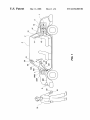
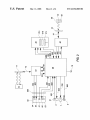
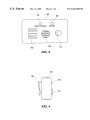
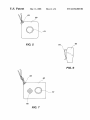
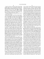
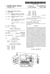
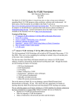
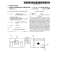
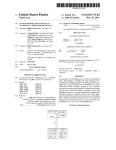
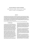
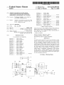
US006532360B1
(12) United States Patent
Shalfer
(54)
(10) Patent N0.:
(45) Date of Patent:
MOBILE SECURITY SYSTEM WITH
CELLULAR TRANSCEIVER, POSITION
REPORTING AND REMOTE ACTUATION
5,742,666 A
5,786,789 A
5,805,055 A
M. Bennett Sha?'er, 514 N. Bluff St.,
St. George, UT (US) 84770
(*)
Subject to any disclaimer, the term of this
patent is extended or adjusted under 35
Notice:
5,894,266 A
5,918,180 A
*
(21) Appl. No.: 09/460,753
(22) Filed:
Dec. 14, 1999
Int. Cl.7
......................... .. H04M 11/00
(52)
US. Cl. ..................... .. 455/404; 455/426; 455/414;
(58)
Field of Search ............................... .. 455/521, 404,
455/456; 340/426
455/426, 345, 414, 456, 422; 342/42, 825;
340/902, 426, 990, 425, 539
References Cited
U.S. PATENT DOCUMENTS
4,100,529 A
7/1978 Evans
4,339,753 A
7/1982 Mawhinney
4,724,538
4,833,477
5,055,851
5,081,667
5,155,689
5,185,779
5,247,564
5,334,974
5,365,570
5,388,147
5,418,537
5,552,789
5,555,286
5,572,201
A
A
A
A
A
A
A
A
A
A
A
A
A
A
5,708,417 A
5,712,619 A
2/1988
5/1989
10/1991
1/1992
10/1992
2/1993
9/1993
8/1994
11/1994
2/1995
5/1995
9/1996
9/1996
11/1996
*
ColiZZa .................... .. 340/426
*
*
4/1999
6/1999
Wood et a1. .............. .. 340/506
Dimino .................... .. 455/456
7/1999 Lin
8/1999 Settles et 81.
5,986,543 A
* 11/1999
6,028,537 A
*
2/2000 Suman et a1.
6,067,007
*
5/2000
A
Johnson .................... .. 340/426
Gioia
... ... ... .
6,133,832 A
* 10/2000 Winder et a1.
6,167,255
*
12/2000
6,262,656 B1 *
7/2001
A
Kennedy
.....
Farrell
Tendler
Sheffer
Drori et 81.
Wortham
Dop et al.
Zicker
Simms et 81.
Boubelik
Grimes
Bird
Schuermann
Tendler
Graham et 81.
340/426
340/10.4
. . . .. 455/414
Byrd et a1. .............. .. 307/10.2
Alpine Electronics, User’s Manual, Alpine Mobile Mayday
System (On—Guard), ATX Technologies, Inc. (1999).
NeWs Release, Cars: Calling for Help, Automatically, by
Ann M. Job, Sep. 13, 1999.
* cited by examiner
Primary Examiner—EdWard F. Urban
Assistant Examiner—KhaWar Iqbal
(74) Attorney, Agent, or Firm—TraskBritt
(57)
ABSTRACT
A mobile security system for use in an automobile or other
vehicle, Which activates a cellular phone to automatically
dial an emergency telephone number and plays a voice
recording including position information provided by the
vehicle operator. The vehicle operator is prompted to record
neW position information When the vehicle ignition is turned
off. The system can be remotely activated by a Wireless
transmitter device Which generates an RF signal When a
“panic button” is depressed. Components of the security
system include a cellular telephone, RF receiver device,
recording device, and controller. A speaker and microphone
permit tWo-Way communication betWeen the vehicle opera
tor and emergency personnel.
1/1998 Tallman et a1. ........ .. 340/425.5
1/1998 Simkin
340/426
. . . ..
OTHER PUBLICATIONS
(51)
(56)
9/1998
11/1998 Revell et 81.
5,926,752 A
5,933,074 A
U.S.C. 154(b) by 0 days.
Mar. 11, 2003
4/1998 Alpert
7/1998 Janky
5,838,237 A
(76) Inventor:
US 6,532,360 B1
14 Claims, 4 Drawing Sheets
U.S. Patent
Mar. 11, 2003
Sheet 1 0f 4
US 6,532,360 B1
.GEF
U.S. Patent
Mar. 11,2003
Sheet 3 0f 4
54
50
WEAK SIGNAL
READY
%
I:
j
52
US 6,532,360 B1
\
53
51
FIG. 3
5O
56 \
/
fié
>//54
E;
FIG. 4
U.S. Patent
Mar. 11,2003
Sheet 4 0f 4
US 6,532,360 B1
60
61
FIG. 5
64
60
FIG. 6
US 6,532,360 B1
1
2
MOBILE SECURITY SYSTEM WITH
The inventive system has the further advantage that it can
CELLULAR TRANSCEIVER, POSITION
be activated by a user that is either inside or outside of the
REPORTING AND REMOTE ACTUATION
vehicle.
It has the further advantage that either a pre-recorded
BACKGROUND OF THE INVENTION
1. Field of the Invention
The invention relates generally to the ?eld of personal
security systems, the ?eld of vehicle emergency signal and
position transmission systems, and to the ?eld of mobile
telephone systems for emergency and security use. It relates
emergency message can be transmitted, or the vehicle user
may establish direct tWo-Way communication With an emer
gency operator.
10
BRIEF DESCRIPTION OF THE SEVERAL
VIEWS OF THE DRAWINGS
speci?cally to systems including cellular telephones capable
FIG. 1 depicts the components of the invention.
of automatically dialing a preset emergency telephone num
ber and activating a voice recording for relaying location
and identi?cation information.
FIG. 2 is a schematic diagram of the invention.
2. Statement of the Art
15
Systems for generating and transmitting emergency sig
nals are knoWn in the prior art. These include systems for use
on boats and ships, cars or trucks, and systems to be carried
on a person. Cellular phone systems for dialing a preset
activation device.
FIG. 6 is a side vieW of the remote activation device of
FIG. 5.
emergency number and transmitting a position signal rep
resenting the current position of the vehicle, or, in some
cases, the last recorded position of the vehicle are also
knoWn in the art. In the prior art, position information is
FIG. 7 shoWs an alternative embodiment of the remote
activator device.
obtained from a GPS or LORAN system, or determined by
triangulation (or comparable calculation) from signal
25
DETAILED DESCRIPTION OF THE
INVENTION
An example of a presently preferred embodiment of the
invention is shoWn in FIG. 1. The main components of the
invention are located in alarm box 1, Which is preferably
installed in a hidden location, for example the trunk 2 of
vehicle 3, as shoWn here. The main components of the
strength in cells of a cellular phone system. The prior art
includes systems in Which GPS or similar coordinates are
translated to a local street address for more convenient
location of the vehicle or individual. Prior art systems have
been activated by various means, including a “panic button”,
car alarm activation, airbag deployment detector, or by
device include cellular telephone 10, controller 20, record
ing device 30, and radio frequency (RF) receiver device 40.
pressing a key or sequence of keys on a telephone keypad.
There remains a need for an alarm system Which is
inexpensive, provides clear information about vehicle
position, and can be activated by a user Who is either inside
FIG. 3 is a front vieW of the user interface box.
FIG. 4 is a side vieW of the user interface box.
FIG. 5 is a front vieW of one embodiment of the remove
35
or outside the vehicle.
Cellular telephone 10 is connected to antenna 11 via cable
12; RF receiver device 40 is connected to antenna 13 via
cable 14. Antennas 11 and 13 are preferably mounted in the
rear WindoW 4 of vehicle 3, but alternatively may be
mounted in any other location Which provides acceptable
SUMMARY OF THE INVENTION
signal reception.
The present invention includes a mobile security system
A message providing identifying information (e.g., user
name, vehicle license plate number, etc.) and location infor
for use in an automobile or other vehicle and Which, When
activated, uses a cellular telephone to dial a pre-set emer
mation can be recorded With recording device 30. In the
event of an emergency, the user activates the device either by
gency telephone number and play a voice recording Which
states the location of the vehicle and provides other identi
fying information. The system also permits direct voice
communication betWeen the occupant of the vehicle and the
pressing a button 51 on user interface 50 Which is mounted
inside vehicle 3, or by pressing a button 61 on remote
45 activation device 60 Which the vehicle user 70 carries on his
contacted emergency operator. The system can be activated
or her person. Remote activation device 60 sends an RF
by depressing a sWitch or button on a user interface box
signal to receiver device 40, Which signals controller 20.
mounted in the vehicle, or by pressing a panic button on a
Controller 20 activates cellular telephone 10 to dial a
remote activation device Which the operator carries on his or
pre-programmed emergency telephone number and activates
her person. The remote activation device transmits an RF
recording device 30 to play the pre-recorded emergency
signal to a transceiver mounted in the vehicle Which then
message Which includes identi?cation and location informa
tion. The controller may also be programmed to activate the
vehicle horn 7 or lights 9, respectively, via lines 700 or 900,
or disable the vehicle upon receipt of a signal from the
initiates dialing of the cellular telephone and transmission of
the recorded emergency message. The remote activation
device makes it possible for the user to activate the device
from any location in the general vicinity of the vehicle, as
Well as from inside the vehicle, thereby greatly enhancing
the utility of the security system. The system utiliZes a voice
recording of position information Which is recorded by the
55
to activate cellular telephone 10 to dial the pre-programmed
emergency telephone number; hoWever, instead of activat
ing recording device 30 to playing a pre-recorded message,
operator of the vehicle and updated as needed. By using a
user-recorded position message, the complexity and cost of
the device is considerably reduced in comparison to systems
Which utiliZe more costly GPS devices. Moreover, the
tWo-Way communication betWeen the user and emergency
operator is enabled. The system can be reset and transmis
sion halted by pressing reset sWitch 18, Which is mounted on
alarm box 1. Reset sWitch 18 is covered, recessed, or
position message can include details Which are not provided
by other types of position signals.
The inventive system has the advantage that it can be
manufactured relatively inexpensively, since it does not
utiliZe a costly GPS.
remote activation device 60. If button 51 on interface 50 is
depressed, a signal is sent to controller 20, Which causes it
65
otherWise protected to prevent it from being depressed
accidentally. Alternatively, the system may be reset using a
reset button located on the remote activation device 60, on
user interface 50, or elseWhere in the system.
US 6,532,360 B1
4
3
record a position message indicating the current (or most
Alarm boX 1 may be constructed of metal or other durable
recent) location of the vehicle, the location description
material, and is sized to contain cellular telephone 10,
controller 20, RF receiver device 40, and recording device
30. All components residing Within alarm boX 1 are prefer
ably poWered by the 12 Volt DC vehicle battery 5, Which is
recorded by the user, a message containing identifying
information pertaining to the vehicle or driver (e.g. vehicle
make and/or model, license plate number, driver name
and/or driver’s license number, etc.), and other messages
Which may be used in the practice of the invention. Record
ing device 30 preferably includes a plurality of memory or
recording locations 31a, 31b, 31c, etc. Where the various
connected to alarm boX 1 by cables 5001 and 5002.
Alternatively, it Would be possible to provide a separate
poWer supply (e.g., battery) for the components of the
invention. Remote activation device 60 is packaged sepa
rately and is preferably poWered by a battery.
10
A schematic diagram of the components of the inventive
system is given in FIG. 2.
Cellular telephone 10 is a conventional cellular telephone
Which has been modi?ed so that its voice output signal is
messages can be stored and from Which the messages can be
retrieved. Recording device 30 further includes audio input
301, audio output 302, memory select input 303, and func
tion select input 304. These are preferably digital inputs and
outputs, Which may be either parallel or serial. Audio input
sent out on line 103, so that it may be routed to speaker 52 15 301 and output 302 must have suf?cient throughput to
transmit a signal of acceptable quality in a reasonable
in user interface 50 via line 502. Cellular telephone 10
amount of time. Memory select input 303 accepts an input
signal Which represents the memory location in Which the
accepts as input 101 either the output signal 304 from
recording device 30 or the audio signal on line 503 from
microphone 53 in user interface 50. In an alternative
desired message is to be stored, or from Which it is to be
retrieved. Function select input accepts an input signal
Which indicates the function to be performed by recording
embodiment of the invention, audio input 101 may originate
from microphone 62 in remote activation device 60. The
audio signal Would be sent from receiver device 40 to
controller 20 via line 402, and from there to cellular tele
phone 10. Cellular telephone 10 is pre-programmed With a
desired emergency number (e.g., 911, a private security
device 30, ie Whether it is to record the signal on audio
input 301 in the selected memory location or play the
message in the selected memory location on audio output
25
company, police, or other emergency service provider) in the
usual manner; hoWever, telephone 10 is modi?ed so that
tions of inputs and outputs may be suitable for use in the
invention, and that the invention is not limited to the
auto-dialing is initiated upon receipt of an activation signal
particular con?guration described here.
on line 102. The audio input received on line 101 is
converted to a cellular telephone signal Which is sent to
antenna 11 via line 12 and transmitted to cellular telephone
transceiver device 70 and routed to the emergency service
provider. Cellular voice signals from the contacted emer
gency service are picked up by antenna 11, carried to cellular
telephone 10 on line 12, and output from cellular telephone
302. It Will be appreciated by those of ordinary skill in the
art that various recording devices having various combina
When a sensor 81 on the ignition 8 of vehicle 3 detects
35
10 on line 103. If the cellular phone 10 is not receiving a
that ignition 8 has been shut off, a signal is generated on line
801. On detection of this signal, controller 20 generates
signals memory select line 303 and function select line 304
causing recording device 30 to play a prompt message stored
in memory location 31a on audio output 302. The prompt
message, Which is routed to speaker 52 on line 502, instructs
strong enough signal to transmit, it generates a signal on line
504 Which causes Weak signal indicator light 54 in interface
boX 50 to be illuminated. If cellular phone 10 is receiving a
the vehicle user to record a neW location description.
strong enough signal for transmission, it generates a signal
location description should be recorded. Asignal on function
select line 304 enables recording device 30; the user speaks
on line 505 Which causes ready signal indicator light 55 in
interface boX 50 to be illuminated.
RF receiver device 40 is a radio frequency (RF) receiver.
RF receiver device 40 is connected to antenna 13 via cable
14. RF receiver device 40 is tuned to receive RF signals
Which are generated by remote activation device 60. RF
signals transmitted by remote activation device 60 include
an alarm signal Which is generated When a “panic button” 61
Though less preferred, it Would also be possible to generate
a beep or other sound to indicate to the user that a neW
into microphone 53, and the signal from microphone 53 is
45
carried to controller 20 via line 503, routed to recording
device 30 on audio input line 301, and recorded in memory
location 31b. In alternative embodiments of the invention,
the voice signal to be recorded could originate from micro
phone 62 in remote activation device 60, or another source.
In the preferred embodiment of the invention, recording
is pressed, and, optionally, an audio signal picked up by a
device 30 also stores a recording of identi?cation informa
microphone 62 in remote activation device 60. RF receiver
tion (driver name, vehicle license plate number, etc.), e. g., in
device 40 sends a noti?cation signal on line 401 to controller
memory location 31c. The identi?cation information is
preferably recorded at the time that the inventive system is
installed in the vehicle, and updated only as needed; it Would
not be necessary, and indeed Would probably be inconve
nient and time-consuming, to record identi?cation informa
20 When the alarm signal is received from remote activation
device 60. The audio signal originating from microphone 62
is transmitted to controller 20 on line 402, and from there is
routed to cellular phone 10 on audio input line 101. RF
receiver device 40 receives a reset signal from controller 20
on line 403. The reset signal causes the receiver device to
stop sending to controller 20 and commence Waiting for an
alarm signal from remote activation device 60. In some
55
tion each time the location information Was recorded.
Recording device 30 may also store a greeting or intro
ductory message, e. g. in memory location 31d, Which Would
be played at the start of an emergency call. In the event that
an emergency occurs and the inventive system is activated,
embodiments of the invention it may be desirable to use a
device capable of both receiving and transmitting signals
(i.e., a transceiver) in place of receiver device 40, for
controller 20 Would send an activation signal to recording
device 30 causing it to play back, in a predetermined
sequence, the greeting, location, and identifying information
stored in memory locations 31d, 31c, and 31b. The activa
example, if it Were desired to transmit signals back to remote
activation device 40 to permit tWo-Way communication.
Recording device 30 is used to record, store and replay a
number of voice messages used by the inventive system.
These include a prompt message Which instructs the user to
65
tion signal could consist of a sequence of signals on memory
select input 303, specifying the memory locations of the
message components, accompanied by a “play” signal on
US 6,532,360 B1
5
6
function select input 304, instructing the recording device to
it to the user’s clothing, such as clip 64, or loop 63 or similar
play back the messages in the indicated memory locations.
The messages Would be played on output line 302 and routed
to cellular telephone 10 via line 101 by controller 20
folloWing dialing of the emergency number. It Will be
appreciated that various message components may be
combined, and the practice of the invention is not limited to
means Which permit it to be attached to a key chain or
necklace. A ?rst example of remote activation device 60 is
depicted in FIGS. 5 and 6. This embodiment of the device
includes activation sWitch (button) 61, Which causes activa
tion of remote activation device 60 to transmit an RF alarm
signal Which is picked up by RF antenna 13 and received by
recording and combining three message components from
RF receiver device 40. Receiver device 40 sends an activa
three memory locations, as described here. Moreover, it may
be desirable to use a larger number of prompts in the system,
20 to activate cellular telephone 10 to dial the pre
tion signal to controller 20 via line 401, causing controller
programmed emergency message and activate recording
device 30 to play the prerecorded message composed of
greeting, location, and identi?cation components, Which is
e.g., to prompt the user to record the identi?cation
information, to provide instructions on system use, etc., and
these also may be stored in and retrieved from recording
device 30. The use of recording device 30 for recording
location information eliminates the need for using a costly
15
GPS or similar system. Moreover, the user may record
details on location not available in global coordinates or
even street addresses (eg “at the back of the building”, “on
the third level of the parking garage”, or “in the northbound
lane of the highWay”) Which may signi?cantly aid emer
gency personnel in locating the vehicle or driver.
User interface 50 is preferably mounted in the front
portion of the passenger compartment of vehicle 3, eg
above the rear vieW mirror, as shoWn in FIG. 1. Interface box
50 is illustrated in more detail in FIGS. 3 and 4. It includes
25
a speaker 52 and microphone 53 Which are used in providing
voice prompting by the system and recording of messages
by the user, as described previously in connection With the
recording device. Speaker 52 and microphone 53 may be of
the type used in cellular phones. User interface box 50 also
includes a sWitch 51 Which is preferably a button (a “panic
button”). If sWitch 51 is activated (i.e. pressed, in the case
that it is a button) controller 20 activates cellular phone 10
to dial the pre-programmed emergency number. The audio
signal from microphone 53 is carried to controller 20 on line
503, and from there routed to cellular phone 10 on line 101,
to be transmitted to the cellular telephone transceiver device
71 for routing to the emergency service provider. The signal
then transmitted to the emergency operator by cellular
telephone 10, as described previously. Optionally, the con
troller 20 can be con?gured to cause the vehicle horn 7 to
honk or to disable the vehicle ignition 8 if an alarm signal
is received from remote activation device 60.
An alternative embodiment of remote activation device 60
is shoWn in FIG. 7. This embodiment of the device includes
all the features included in the embodiment of the invention
shoWn in FIGS. 5 and 6, and also includes a microphone 62
for picking up an audio signal Which is transmitted to RF
receiver device 40, sent to controller 20 on line 402, and
routed to cellular telephone 10 for transmission to the
emergency operator. This alloWs the user to provide a verbal
message in addition to the pre-recorded location and iden
ti?cation messages, and also alloWs the emergency operator
to listen to any activity (sounds of distress, etc.) taking place
in the vicinity of remote activation device 60. A further
alternative Would be to include a receiver and a speaker in
remote activation device 60, to alloW tWo-Way communica
tion betWeen the user and the emergency operator; hoWever,
inclusion of additional components Would lead to an
35
increase in the siZe and Weight of the device.
It is anticipated that user interface box 50 Would be used
to activate the system in cases Where the vehicle user could
from the emergency service is sent to controller 20 on line
readily reach and press button 51, and in Which tWo-Way
communication Was desired, for example, if the vehicle had
103, and from there routed to speaker 52. This alloWs direct
tWo-Way communication betWeen the occupant of the
vehicle and the contacted emergency personnel.
suspicious activity outside the vehicle. Remote activation
an engine breakdoWn or ?at tire, or if the vehicle user noted
device 60 Would be used in cases Where the vehicle user Was
outside the vehicle, or Was inside the vehicle but unable to
Weak signal indicator light 54 and ready signal indicator
light 55 are mounted on the outside of box 50. Weak signal
indicator light 54 is preferably a red light emitting diode
(LED) and ready signal indicator light 55 is preferably a
green LED. HoWever, it Will be appreciated that other colors
and types of lights may be used in the practice of the
invention. A cable 500 containing lines 501, 502, 503, 504
and 505 from sWitch 51, speaker 52, microphone 53, Weak
45
reach the user interface (e. g., if the person Was injured by an
accident) or needed to contact emergency personnel Without
attracting attention (e.g., if an intruder Was in the vehicle).
Controller 20 includes sWitching, timing, and control
logic. As Will be appreciated from the foregoing descriptions
of the various components of the invention, controller 20
controls the routing of input and output signals betWeen
signal indicator light 54 and ready signal indicator light 55,
other components of the invention. Controller 20 also must
respectively, runs from interface box 50 to alarm box 1, as
shoWn in FIG. 1. Interface box 50 may be constructed of
plastic. A metal clip 56 on the rear of box 50 may be used
to mount interface box 50 to the plastic strip 6 found
betWeen the Windshield and “headliner” of vehicle 3.
Alternatively, interface box 50 may be mounted to the
Windshield, rear vieW mirror, sun visor, or location in the
generate appropriate delays betWeen actions carried out by
other components of the invention, for example, betWeen
55
generation of a prompt to record position information and
actual recording of the information, or betWeen automatic
dialing of the pre-programmed emergency number and
playing and transmission of the recorded message contain
ing identi?cation and location information. Controller 20
vicinity of the driver, With the use of clamps, suction cups,
may include analog and digital circuitry, programmable
adhesive, etc., as knoWn in the art.
Remote activation device 60 may be carried on the
vehicle user’s person, and is used to provide remote activa
memory devices, a microprocessor, and other components as
knoWn to those of ordinary skill in the art. Controller 20 may
tion of the system. Remote activation device 60 is preferably
designed to be small enough to carry easily and to have an
inconspicuous appearance. For example, it may be made to
be connected to sWitches Which alloW the user to select
various options, such as Whether controller 20 should cause
the vehicle horn 7 to honk or disable the vehicle ignition 8
65 if an alarm signal is received from remote activation device
resemble a pager, as depicted in FIGS. 5, 6 and 7. Remote
60. It Will be appreciated that various methods of construct
activation device 60 preferably includes means for attaching
ing controller 20 may be devised by those of ordinary skill
US 6,532,360 B1
7
8
in the art, and the practice of the invention is not limited to
a particular embodiment thereof.
While the present invention has been described and
illustrated in terms of certain speci?c embodiments, those of
ordinary skill in the art Will understand and appreciate that
it is not so limited. Additions to, deletions from and modi
?cations to these speci?c embodiments may be effected
Without departing from the scope of the invention as de?ned
by the claims. Furthermore, features and elements from one
speci?c embodiment may be likewise applied to another
embodiment Without departing from the scope of the inven
capable of picking up and audio signal transmitting said
audio signal from said remote activation device to said
receiver device and routing said audio signal to said cellular
telephone by said controller.
6. The mobile security system of claim 5, Wherein said
user interface device further comprises a sWitch capable of
activation by a user, and Wherein activation of said sWitch by
said user causes transmission of a third activation signal to
said cellular telephone causing dialing of said prepro
grammed emergency telephone number, and Wherein acti
vation of said sWitch further causes routing of an audio
tion as de?ned herein.
signal from said microphone in said user interface device to
What is claimed is:
1. A mobile security system for use in a vehicle compris
ing:
a cellular telephone con?gured for receiving a ?rst acti
said cellular telephone for transmission and routing of the
audio signal received by said cellular telephone from said
15
vation signal and, upon receipt of said ?rst activation
signal, dialing a preprogrammed emergency telephone
7. The mobile security system of claim 6, Wherein said
emergency message comprises a recording of location infor
mation.
8. The mobile security system of claim 1, Wherein said
user interface device further comprises a microphone
capable of picking up an audio signal, and Wherein said
audio signal may be routed from said user interface device
to said cellular telephone by said controller.
9. The mobile security system of claim 8, Wherein said
emergency message comprises a location description.
10. The mobile security system of claim 8, Wherein said
user interface device further comprises a sWitch capable of
activation by a user, and Wherein activation of said sWitch by
number of an emergency service provider and trans
mitting an emergency message to said emergency ser
vice provider;
a user interface device comprising a microphone and a
speaker;
a recording device con?gured for recording, storing, and
playing back a plurality of messages, said emergency
message comprised of at least one of said plurality of
messages, said recording device con?gured for receiv
ing a second activation signal and, upon receipt of said
second activation signal, sending said emergency mes
sage to said cellular telephone;
said user causes transmission of a third activation signal to
said cellular telephone causing dialing of said prepro
grammed emergency telephone number, and Wherein acti
a remote activation device comprising a transmitter and a
user input device, said remote activation device con
?gured for transmitting an arm signal upon recent of an
input on said user input device;
a receiver device tuned to receive said alarm signal
transmitted by said remote activation device, and con
emergency service provider to the speaker of said user
interface device.
vation of said sWitch further causes routing of an audio
35
signal from said microphone to said cellular telephone for
transmission and routing of the audio signal received by said
cellular telephone to the speaker of said user interface
device.
?gured for generating a noti?cation signal upon receipt
of said alarm signal; and
11. The mobile security system of claim 1, Wherein at
least one of said plurality of messages stored by said
recording device is a prompt message, Wherein said prompt
a controller con?gured for receiving said noti?cation
signal from said receiver device and, upon receipt of
said noti?cation signal, generating said ?rst activation
signal for sending to said cellular telephone to initiate
message is con?gured for playing through a speaker to
instruct a user to state a location description, and Wherein
dialing of said preprogrammed emergency telephone
said location description is recorded by said recording
number and generating said second activation signal for
sending to said recording device to initiate sending of
device.
45
said emergency message to said cellular telephone from
said recording device;
Wherein said user interface device, said receiver device,
and said controller are con?gured for placement Within
said vehicle, and Wherein said remote activation device
is con?gured for generating an alarm signal for recep
tion by said receiver device When said remote activa
ignition sWitch, and Wherein said prompt message is played
and said recording device is enabled to record said location
description upon detection of shutoff of said ignition sWitch.
14. A mobile security system for use in a vehicle, said
tion device is located at a distance from said receiver
mobile security system comprising:
device.
2. The mobile security system of claim 1, Wherein said
emergency message comprises a location description.
3. The mobile security system of claim 1, Wherein the
vehicle comprises a horn, and Wherein upon receipt of said
12. The mobile security system of claim 11, Wherein said
emergency message comprises a location description.
13. The mobile security system of claim 11, Wherein said
vehicle comprises an ignition sWitch and a detector associ
ated With said ignition sWitch for detecting shutoff of said
55
a cellular telephone con?gured for receiving a ?rst acti
vation signal and, upon receipt of said ?rst activation
signal, dialing a preprogrammed emergency telephone
number of an emergency service provider and trans
noti?cation signal, said controller causes said horn to honk
mitting an emergency message to said emergency ser
at least once.
vice provider;
a user interface device comprising a microphone, a
4. The mobile security system of claim 1, Wherein the
vehicle comprises headlights and tail lights, and Wherein
upon receipt of said noti?cation signal, said controller
speaker, and a user-activated sWitch;
a recording device capable of recording, storing, and
causes one or more of said headlights and said tail lights to
be illuminated.
5. The mobile security system of claim 1, Wherein said
remote activation device further comprises a microphone
65
playing back a plurality of messages, said emergency
message comprised of at least one of said plurality of
messages, said recording device con?gured for receiv
ing a second activation signal and, upon receipt of said
US 6,532,360 B1
10
second activation signal, sending said emergency mes
sage to said cellular telephone;
said emergency message to said cellular telephone from
said recording device;
a remote activation device comprising a transmitter and a
Wherein said user interface device, said receiver device
and said controller are con?gured for placement Within
said vehicle, Wherein said remote activation device is
user-activated sWitch, said remote activation device
capable of transmitting a RF alarm signal upon activa
tion of said user-activated sWitch of said remote acti
con?gured for generating an alarm signal for receiving
vation device;
by said receiver device When said remote activation
receiver device connected to an antenna, tuned to
device is located at a distance from said receiver
receive said RF alarm signal transmitted by said remote
activation device and con?gured for generating a noti
?cation signal upon receipt of said RF alarm signal; and
device, Wherein said plurality of messages stored by
controller con?gured for receiving said noti?cation
signal from said receiver device and, upon receipt of
said noti?cation signal, generating said ?rst activation
signal for sending to said cellular telephone to initiated
dialing of said preprogrammed emergency telephone
number and generating said second activation signal for
sending to said recording device to initiate sending of
10
said recording device includes at least one prompt
message instructing a vehicle user to state position
information, and at least tWo emergency message com
ponents for combining to form said emergency
15
message, at least one of said at least tWo emergency
message components comprising a location descrip
tion.
UNITED STATES PATENT AND TRADEMARK OFFICE
CERTIFICATE OF CORRECTION
PATENT NO.
: 6,532,360 B1
Page 1 of 2
APPLICATION NO. : 09/460753
DATED
INVENTOR(S)
: March 11, 2003
: M. Bennett Shaffer
It is certified that error appears in the above-identi?ed patent and that said Letters Patent is
hereby corrected as shown below:
In the speci?cation:
COLUMN 2,
COLUMN 2,
COLUMN 2,
COLUMN 2,
COLUMN 2,
LINE 14,
LINE 15,
LINE 16,
LINE 33,
LINE 47,
COLUMN 3,
LINE 17,
COLUMN 3,
LINE 22,
COLUMN 3,
LINE 27,
change “however, telephone” to --however,
cellular telephone-
COLUMN 3,
COLUMN 3,
COLUMN 3,
COLUMN 3,
LINE 32,
LINE 38,
LINE 39,
LINE 42,
COLUMN 3,
LINE 62,
change “device 70” to --device 71change “in interface” to --in user interfacechange “box 50 to” to --50 tochange “interface box 50” to --user interface
50change “place of receiver” to --place of RF
COLUMN 4,
LINE 12,
change “select input 303,” to --select line
COLUMN 4,
LINE 13,
change “select input 304.” to --select line
COLUMN 4,
COLUMN 4,
LINE 17,
LINE 20,
COLUMN 4,
LINE 33,
COLUMN 4,
LINE 58,
change “interface box.” to --interface.change “interface box.” to --interface.change “of the remove” to --of the remotechange “via cable” to --via cable or linechange “signal to receiver” to --signal to RF
receiverchange “signal 304” to --signal 302change “sent from receiver” to --sent from RF
receiver-
receive -
303,304.-
change “select input 303” to --select line 303change “select input accepts” to --select line
304 acceptschange “signals memory” to --signals on
memory-
COLUMN 5,
COLUMN 5,
COLUMN 5,
COLUMN 5,
LINE 24,
LINE 30,
LINE 44,
LINE 52,
COLUMN 5,
LINE 53,
COLUMN 5,
COLUMN 5,
LINE 54,
LINE 55,
change “31d, which” to --31d (not shown),
whichchange “Interface box” to --User interfacechange “interface box 50” to --interface 50change “of box 50.” to --of user interface 50.change “interface box 50” to --user interface
50change “Interface box 50” to --User interface
50change “box 50” to --user interface 50change “interface box 50” to --user interface
50-- and change “strip 6 found” to --strip 6 (not
shown) found-
UNITED STATES PATENT AND TRADEMARK OFFICE
CERTIFICATE OF CORRECTION
PATENT NO.
: 6,532,360 B1
Page 2 of 2
APPLICATION NO. : 09/460753
DATED
INVENTOR(S)
: March 11, 2003
: M. Bennett Shaffer
It is certified that error appears in the above-identi?ed patent and that said Letters Patent is
hereby corrected as shown below:
In the speci?cation (continued):
COLUMN 5,
LINE 57,
COLUMN 6,
LINE 36,
change “interface box 50” to --user interface
50change “interface box 50” to --user interface
50-
Signed and Sealed this
Second Day of October, 2007
m Wart”
JON W. DUDAS
Director ofthe United States Patent and Trademark O?ice