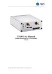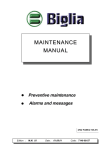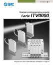
1
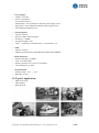
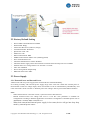
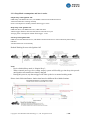
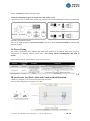
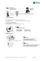
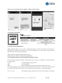
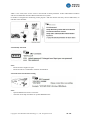
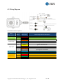
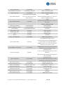
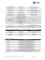
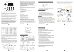
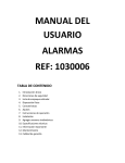
GSM/
GPSALARM
KI
T
AS200USER SGUI
DE
I
P67Rat
ed¦Sat
el
l
i
t
eTr
ac
ki
ng¦Cel
lPhoneCont
r
ol
Content Index
1-Introduction:.................................................................................................................................................3
1.1-Instruction of Safety:.................................................................................................................................3
1.2-Specification..............................................................................................................................................3
1.3-Typical Application:..................................................................................................................................4
1.4-Package Contents:.....................................................................................................................................5
2-Knowlege Before Usage:............................................................................................................................. 5
2.1- How it works?.......................................................................................................................................... 5
2.2 Factory Default Setting............................................................................................................................. 6
2.3 Power Supply............................................................................................................................................ 6
2.4 Transmitter Operation............................................................................................................................... 8
3. Functions and Operation:............................................................................................................................ 9
3.1 Arm/Disarm............................................................................................................................................... 9
3.2 Alarm functions......................................................................................................................................... 9
3.3 Immobilizer Engine...................................................................................................................................9
3.4 Power Saving...........................................................................................................................................10
3.5 3D Accelerator for Shock Alert and Crash accident Detection.............................................................. 10
3.6 Voice Listen-in.........................................................................................................................................11
3.7 Switch ON/Off Siren............................................................................................................................... 12
3.8 Battery Low.............................................................................................................................................12
3.9 Recovery Factory Default....................................................................................................................... 13
3.10 Remote Reboot......................................................................................................................................13
3.11 Locate in parking Lot............................................................................................................................ 13
3.12 GPS Tracking features...........................................................................................................................13
4. Get started to use and Installation............................................................................................................. 15
4.1 How to Insert SIMCARD........................................................................................................................15
4.2 Device Configuration.............................................................................................................................. 15
4.3 Wiring Diagram.......................................................................................................................................17
5. Problem Shooting......................................................................................................................................18
APPENDIX................................................................................................................................................... 18
Copyright © 2015 Shenzhen ANB Technology Co., Ltd. All rights reserved.
2 / 20
1-Introduction:
AS200 is a IP67 Rated GSM/GPRS/GPS alarm tracking box for multi applications.
This small unit is equipped with Quad Bands GSM/GPRS module, Hi-sensitivity GPS receiver and 3D
Accelerometer. It’s also can be connected with optional wireless/wired accessories like PIR senor, RF Key
Fob, Alarm siren and Relay for external electronics device control
It supports both GPS tracking and backup LAC/CID tracking, which brings an idea solution with no blind
tracking both indoor and outdoor.
1.1-Instruction of Safety:
Do not disassemble the device more than it is allowed. If the device is damaged, the power supply
cables are not isolated or the isolation is damaged, before unplugging the power supply, do not
touch the device.
All wireless data transferring devices produce interference that may affect other devices which are
placed nearby.
The device may be fitted only by qualified personnel.
The device must be firmly fastened in the predefined location.。
The device is susceptible to water and humidity in environment with IP class greater than IP67.
Any installation and/or handling during a lightning storm is prohibited.
Ensure that the batteries are not immersed in water. When stored, keep the device in a cool and dry
place.
Ensure that device and batteries are not exposed to hot surfaces or direct sunlight.
1.2-Specification
•
•
•
•
•
Physical Specification:
Dimension: 56*78*38mm
Weight:
Enclosure: ABS
IP Rating: IP67
Connector: 14Pin
Copyright © 2015 Shenzhen ANB Technology Co., Ltd. All rights reserved.
3 / 20
•
•
•
Power Supply:
Voltage: 9-36V DC
Power Consumption:
70-150mA(All active)/
Simple Sleep:<15mA (GSM ON, GPS Off, Alarm trigger active)
Deep Sleep: <5mA (GSM Off, GPS Off, Alarm trigger active)
Internal Battery:800mAH, 3.7V
•
•
•
•
•
GPS Navigation:
Antenna: Internal
Receiver: uBlox NEO 6M engine
Sensitivity: -162dBm
Navigation Update: 1Sec
TTFF: Cold Starts: 29s/Aided Starts: <1S/ Hot Starts: <1S
•
•
GSM:
Antenna: Internal
Modem: QUECTEL M35 /Quad Bands:850/900/1800/1900MHz
•
•
•
•
Radio Frequency:
Working frequency: 433MHz.
Code: 1527/2240 study
Working Voltage: 12V ( 27A 12V dry battery)
Control Distance: 20-50M
•
•
Environmental:
Working Temp.: -20℃ ~ +75℃
Humidity: 20-95%
1.3-Typical Application:
•
•
•
Motorcycle/ATVs
Motor Homes
Boats & Yacht
Copyright © 2015 Shenzhen ANB Technology Co., Ltd. All rights reserved.
4 / 20
1.4-Package Contents:
1.4.1Standard Package Contents
1.4.2 Optional Accessories
Note:
Please kindly noted that optional accessories is not a standard parts inside the package. They need to
purchase separately from Manufacturer.
2-Knowlege Before Usage:
2.1- How it works?
The AS200 mainframe works as a host box with multi input/outputs. The mainframe will process to get
GPS location and various working status from inputs and send those information to preset Phone Numbers
or IP/Port Server via GSM network. Cell Phone or Server software can send commands to control outputs
action and also acquire different information by available commands.
Copyright © 2015 Shenzhen ANB Technology Co., Ltd. All rights reserved.
5 / 20
2.2 Factory Default Setting
•
•
•
•
•
•
•
•
•
•
•
•
•
•
•
Device SMS Command Password: 1234
IP/Port/APN: Empty
Alarm Alert Phone No.(A/B/C/G): Empty
Arm/Disarm Status: Disarmed
Speed Over Limit: Off
GEO Fence: Off
Data Transmit Mode: SMS
GPRS Communication Mode: TCP /(UDP supported)
Siren: Internal Buzzer ON
Automatic Immobilizer in Alarm: Disabled
Automatic Power supply switch from external to internal when external power low: Enabled
External Power low voltage Alert Level: less than 11.5V DC
Auto Arm: Disabled
Power Saving Mode: Simple Sleep
SMS Data Time Zone: GMT
2.3 Power Supply
2.3.1 External Power and Internal Power
AS200 works with two power supply mode: External Power and Internal Battery.
It's working normally with external power supply range from 9-36V DC. When the external power is
disconnected or with low voltage output, device will switch to work on internal battery automatically. And
it also will send" Circuit Cut Off" or "External power low voltage" Alert to preset Alerts Phone Numbers.
Note:
- When external Power is less than 5V DC, system will treat as disconnected
- Default External Power low voltage alert level is 11.5V DC. This parameter is available for
configuration according to different application environment. Configuration commands please refer to
APPENDIX “Available SMS commands” list.
-
When both external and internal power supply in low status, device will get into deep sleep
mode by external power source
Copyright © 2015 Shenzhen ANB Technology Co., Ltd. All rights reserved.
6 / 20
2.3.2 Sleep Mode consumptions and how it works
Simple Sleep when Ignition Off:
GSM Sleep with SMS/Call Active, NO GPRS Connection and GPS shut down
All Alarms Detection working normally
Power Consumption in standby without alarm trigger: 10mA
Deep Sleep when Ignition Off:
GSM Shut down, NO SMS/Call active, GPS shut down
Alarms trigger detection: Off 6seconds, detect 2seconds in recycle
Average power consumption without alarm trigger: <5mA
NO sleep when Ignition Off:
GSM all ON with SMS/Call active, and GPRS connected with Server with continuously data sending
GPS ON
All alarm detection work normally
Default Working Process after Ignition Off:
Note:
- Device default Sleep mode is “Simple Sleep”;
- When external power get low voltage output, system will forcibly get into deep sleep mode
until ignition was started on or battery charged
- During this process, any alarm trigger will wake up device to normal working mode.
Please check following Battery lasting time based on different Sleep Mode Settings:
Copyright © 2015 Shenzhen ANB Technology Co., Ltd. All rights reserved.
7 / 20
2.4 Transmitter Operation
2.4.1 Transmitter Button functions
Arm
Panic (Siren)
Disarm
Mute
Arm: Buzzer sound once, or direction light flash once
Disarm: Buzzer Sound Twice or direction light flash twice.
Mute Key: In siren sounding, press this button to stop the sounding.
In panic, Activate Siren to sound. Or in parking lot, press this button for car finding.
2.4.2 Transmitter OVERRIDE
If your transmitter is lost or damaged, or the transmitter battery is flat, the system can be
overridden by Ignition switch conjunction with Panic Button.
Please follow below process to finish the transmitter overridden operation:
1. Send SMS command to clear all existing transmitter code which stored in the system
2. Disarm the system by SMS command
3. Press and Hold Panic button
4. Switch Key from ACC off to ON position continuously 7times
5. Buzzer will sound once to indicating Overridden mode entered
6. Press any button of the transmitter
7. Buzzer sound twice again to indicate override success and exit overridden mode
If system get into overridden mode, and no transmitter button was pressed or did not receive any
incoming signal during 20seconds, buzzer will sound bibibi three times and exit override mode
After you pressed the transmitter button during overridden mode, but system failed in accident
due to unexpected reason, system also will sound bibibi three times to indicate failure.
Copyright © 2015 Shenzhen ANB Technology Co., Ltd. All rights reserved.
8 / 20
You can start the process again until you get it work success.
For other wireless sensor, like Door/window contact, Smoke and gas detectors follow the same
process to integrate them to system.
3. Functions and Operation:
3.1 Arm/Disarm
Automatic Arm:
If the system was configured to allow automatic Arm, it will arm automatically 8Minutes after ignition is
switched OFF, or you can arm the system manually before this time.If the system was Disarmed when
ignition is OFF, it will arm automatically after 8Minutes either.
You can disable this "AUTOMATIC ARM" function by SMS command. Factory Default is disabled.
Enable SMS command: *1234*AutoArmON#
Disable SMS command: *1234*AutoArmOFF#
3.2 Alarm functions
In Armed status, any illegal operation will trigger an alarm action. In alarm, system siren(buzzer) will
sound for 15seconds, and also send alarm alert via SMS and missed call to preset phone numbers A/B/C.
Please check following alarm events alert system:
3.3 Immobilizer Engine
When system received SMS Command *1234*STOP#, it will activate immobilizer to get ignition not
Copyright © 2015 Shenzhen ANB Technology Co., Ltd. All rights reserved.
9 / 20
started. *1234*K# command will deactivate it.
Automatic Immobilize Engine in Armed status and Alarm events:
Upon Alarm events in armed status, system will automatic activate the immobilizer. Default is disabled this
automatic immobilizer function.
You can use SMS command *1234*autoCutON# to activate it. And *1234*autoCutOff# will disable this
automatic feature.
3.4 Power Saving
The system is designed to have different sleep mode when ignition off. In different sleep mode, the power
consumption are different. Details please check <2.3.2 Sleep Mode consumptions and how it
works>.
Please check following Commands for Power saving activate:
3.5
3D Accelerator for Shock Alert and Crash accident Detection
AS200 was designed to use 3D accelerator detecting movement.
Check as following picture to about how it works:
Copyright © 2015 Shenzhen ANB Technology Co., Ltd. All rights reserved.
10 / 20
-
Shocking Alarm:
System will detect all X,Y,Z acceleration, any changes in all X,Y,Z axis will be calculated, every
changes which over 0.1G, system calculated for shocking once, every 5Seconds scan and calculate
once.
We use 5seconds average shocking times as shocking sensitivity.
1=most sensitive
200= Most insensitive.
SMS commands for adjusting shocking sensitivity:
*1234*VS*xxx#
(xxx=001-200)
Switch On/Off Shocking Alarm SMS commands:
*1234*H#
<Switch On shocking Alarm>
*1234*N#
<Switch Off Shocking Alarm>
-
Crash Accident Detecting:
Crash accident has two cases:
1) Knock from front or back
You need to preset the Y axis acceleration value for this impact. Please consult with your distributor about
how to do this.
2) Fall down to two sides
System will detect automatically, no need calibration and setup.
Setup SMS commands:
Setup Crash Parameter
acceleration value on X,Y,Z axis>
Switch Off Crash Alert
Switch On Crash Alert
*1234*CS*-1.0,8.0,-7.0#
<-1.0,8.0,-7.0 means
*1234*GOFF#
*1234*GON#
3.6 Voice Listen-in
Copyright © 2015 Shenzhen ANB Technology Co., Ltd. All rights reserved.
11 / 20
Non-authorized Person do Voice Monitoring SMS command:
*1234*VMxxxxxxxx#
<xxxxxxx is call back phone No. for system>
3.7 Switch ON/Off Siren
By SMS command, user can switch ON/Off siren remotely.
3.8 Battery Low
Copyright © 2015 Shenzhen ANB Technology Co., Ltd. All rights reserved.
12 / 20
3.9 Recovery Factory Default
3.10 Remote Reboot
3.11 Locate in parking Lot
3.12 GPS Tracking features
3.12.1 Query Location
Copyright © 2015 Shenzhen ANB Technology Co., Ltd. All rights reserved.
13 / 20
Open up your google Link in smart phone to check location on map:
3.12.2 Speed Limit Manage
3.12.3 GEO Fencing Management
AS200 maximum allows user to create 25 GEO fencing areas. And the area shape can be cirlular or
rectangular. Considered text message only can contain 140Bytes text, so user need to create multi-areas
with more than one text message command.
GEO fencing alert support both Entry and Exit event.
Details please check following SMS command definition.
*1234*GEOXXYZ,X1,Y1,X2,Y2;0110,X2,Y2,R2;0220,X3,Y3,R3#
In above sample command, it defined 3 GEO fencing areas. First one is rectangular, second and third one
is circular shapes
*1234*
// Command header with password
GEO
// Command Name
XXYZ
//First Area definition for area ID, area shape and events alert type.
XX is area ID. Ranges=00-24, maximum 25Areas supported=Alert type, Y=1 means entry, Y=2 means exit,
Y=3 means alert both in entry and exit. Z=Area shape, Z=0 means circular, Z=1 means rectangular.
X1, Y1, X2, Y2
// Rectangular shape parameter format. (Unit must be degrees, for Western
Copyright © 2015 Shenzhen ANB Technology Co., Ltd. All rights reserved.
14 / 20
and southern value put – before it).Taken value as following chart:
0110,X2,Y2,R2
//Circular shape area parameter format.
In this area, Area ID=01, event alert when entry this area, area shape type is cirlular. X2,Y2 are coordinates
for circle center point. R2 is radius value. See as following picture:
4. Get started to use and Installation
4.1 How to Insert SIMCARD
1).Unscrew the AS200 Box
2).Find the SIMCARD slot on PDB boards
3) Follow below illustration to insert the SIMCARD IN and switch it back.
4.2 Device Configuration
Considering AS200 is a security system, before your usage, please configure it properly according this
manual and get it work well.
4.2.1 Authorization Alert Phone Numbers
In AS200, we defined 4 authorization number for different user roles.
Copyright © 2015 Shenzhen ANB Technology Co., Ltd. All rights reserved.
15 / 20
A/B/C is for owner, B/C are for owner’s close friend or family members. A/B/C authorization numbers
will receive SMS alerts and also Missed call alert from system.
G Number is designed for monitoring center purpose. And this number will only receive SMS alerts, no
call alert to this Number.
4.2.2 Modify Password
Note:
- Password max. length is 4 bytes
- Password can be a combination of letters and numbers
4.2.3 Time Zone Localization Setting
Note:
- System default Time zone is UTC time
- This time zone setup will effect on system SMS data time.
Copyright © 2015 Shenzhen ANB Technology Co., Ltd. All rights reserved.
16 / 20
4.3 Wiring Diagram
Pin Definition Detail explains as:
Wire
Description
Power
Digital Output
Digtal Input
Microphone
RF Receiver
Pin No.
Wire Color
Function/Specification Description
13
Red
Power positive pole, 8-60V DC
14
Black
Power Ground
11
Orange
Connect to Direction light or Alarm Horn
5
Blue
Control External device via Rely
6
Grey
Engine Immobilizer
10
Yellow
Ignition status Detection
8
Brown
Door Status( =0V: Open)
7
Oragne
Panic Button(=0V:effective)
4
Grey
Input signal for Arm/Disarm
9
Blue
Mic+
12
Green
Mic-
1
Red
3.3V Power
2
Green
RF Data
3
Black
Ground
Copyright © 2015 Shenzhen ANB Technology Co., Ltd. All rights reserved.
17 / 20
5. Problem Shooting
APPENDIX
1. Available SMS Commands List
Command Name
SMS Format
System Reply
Setup Center SMS Service No.
*1234*G13480877140#
Armed/Unarmed;G:xxxxxxxx
Delete G Number
*1234*G#
Armed/Unarmed;G:
Setup Alarm alerts No.
*1234*AXXXXX*BXXXXXC
XXXX#
Armed/Unarmed;A:xxxxxB:xxxxxC:xxxxx
Delete A/B/C Number
*1234*A*B*C#
Armed/Unarmed;A:B:C:
Enable Siren Sound
*1234*SIRENON#
SIRENON OK
Disable Siren Sound
*1234*SIRENOFF#
SIRENOFF OK
Query all authorizaiton
Number
Modify Password
*1234*YY#
*1234*E4321#
Armed/Unarmed;A:XXXXXB:XXXXC:XXX
XG:XXXXX
Password has been changed!
Immobilizer
Activate Immobilizer
*1234*STOP#
Enabled;$GPRMC,xxxxxx.xxx,A,xxxx.xxxx,
N,xxxxx.xxxx,E,x.x,xxx.x, xxxxxx,,,A*xx
Immoibilizer
Deactivate Immobilizer
*1234*K#
Disabled;$GPRMC,xxxxxx.xxx,A,xxxx.xxxx,
N,xxxxx.xxxx,E,x.x,xxx.x, xxxxxx,,,A*xx
Recover to factory setting
*1234*V#
Factory Setting Recovered
Reset
Reboot Device remotely
*1234*Z#
Ok;$GPRMC,xxxxxx.xxx,A,xxxx.xxxx,N,xxx
Speed Limit Setup
*1234*SPDxxx#
Speed Over alert activated: xxx Km/h
xx.xxxx,E,x.x,xxx.x, xxxxxx,,,A*xx
Copyright © 2015 Shenzhen ANB Technology Co., Ltd. All rights reserved.
18 / 20
Query Speed Limit
*1234*SPD#
XXXkm/h
Setup SMS Data Time Zone
*1234*GMT+/-XXXX#
GMT+/-XXXX Setup OK!
Query Time zone
*1234*GMT#
GMT+/-XXXX Setup OK!
*1234*GPRS:86307001580606
GPRS
9,211.154.142.150,9114,T,CM
Parameter:863070015806069,211.154.142.15
NET,user,pass#
0,9114,1,CMNET,User,Pass
Setup GPRS Parameter
GPRS
Query GPRS Parameter
*1234*QP#
Parameter:863070015806069,211.154.142.15
0,9114,01,
CMNET,,SMS/SMS+GPRS
Timing report Interval
*1234*ITV0010#
ITV Enabled:60
Ignition Off Report Interval
*1234*AV0060#
AV Enabled:0060
Voice Listen-in
*1234*VM15019417609#
<No reply>
Disable Shock Alert
*1234*N#
Shake Alert Off
Enable Shock Alert
*1234*H#
Shake Alert On
Arm
*1234*S#
Armed forcibly
Disarm
*1234*C#
Unarmed
Query system IMEI No.
*1234*IMEI#
IMEI:012207002358775
UnArmed/Armed; Engine:off/on;
Door:off/on;Immobilizer:enabled/disabled;LA
Query System status
*1234*X#
C:xxxxxx;CID:xxxxx;Signal Strength:xx
$GPRMC,xxxxxx.xxx,A,xxxx.xxxx,N,xxxxx.
xxxx,E,x.x,xxx.x, xxxxxx,,,A*xx
Check GPRMC Format Data
*1234*GPS#
$GPRMC,063231.00,A,2232.64712,N,11355.
45466,E,0.581,195.93,050811,,,A*6C
Time:2011-12-08
12:32:13,V,60Km/H,Heading:60,LAC:2638,C
Acquire Google Link
*1234*P#
ID:0ECF;
http://maps.google.com/maps?hl=en&q=22.53
7222,114.020948
Time:2011-12-08,
Query Coordinates
*1234*GPSD#
12:32:13,V,60Km/H,Heading:60,LAC:2638,C
ID:0ECF,Lat:22.54415,Lon:113.92423
Query System Version
*1234*VER#
Firmware Version:2.01
Setup shock sensitivity level
*1234*VS*xxx#
Vibration Sensitivity:020
Setup Crash Parameter
*1234*CS*-1.0,8.0,-7.0#
Crash Sensitivity -1.0,8.0,-7.0
Switch Off Crash Alert
*1234*GOFF#
Accident Alert Off
Switch On Crash Alert
*1234*GON#
Accident Alert ON
Setup external power low level
*1234*LBxxx#
LB:8.0V
Query power low level
*1234*LBQ#
LB:10.0V
Activate SMS mode only
*1234*SMS#
SMS Mode Activated
Copyright © 2015 Shenzhen ANB Technology Co., Ltd. All rights reserved.
19 / 20
Activate SMS+GPRS mode
*1234*SMS+GPRS#
SMS+GPRS Mode Activated
Simple sleep activate
*1234*SL*O#
Simple Sleep Activated!
Deep sleep activate
*1234*SL*A#
Deep Sleep Activated!
No sleep activate
*1234*SL*C#
Sleep Deactivated!
Sound Siren
*1234*L#
No response, system sound siren 20seconds
Enable Auto Arm
*1234*autoArmON#
Auto Arm Activated
Disable auto Arm
*1234*autoArmOff#
Auto Arm Deactivated
Open battery charger
*1234*CHARGEROPEN#
Charger Activated
Deactivate battery charger
*1234*CHARGERCLOSE#
Charger Deactivated
*1234*GEO0031,+/-DDD.DDD
D,+/-DD.DDDD,+/-DDD.DDD
GEO fencing area
configuration
D,+/-DD.DDDD;
0110,+/-DDD.DDDD,+/-DD.D
Geofence OK
DDD,900000;
0220,+/-DDD.DDDD,+/-DD.D
DDD,1000;;#
Cancel GEO area
*1234*GEO002#
Geofence Deactivated
0331,+/-DDD.DDDD,+/-DD.DDDD,+/-DDD.
Query single GEO area
*1234*GEO03#
DDDD,+/-DD.DDDD
//No
area
Errors
Error Message
Reason Solution
Password Wrong
Key Incorrect!
wrong password, 4digits password only
SMS command format Wrong
Format Incorrect!
All SMS command gets no space character
Setup fail
Setup Failed!
Try again
Query fail
Query Failed!
Try again
Control fail
Control Failed!
Try again
2. Alarm Alert contents
Copyright © 2015 Shenzhen ANB Technology Co., Ltd. All rights reserved.
20 / 20