1
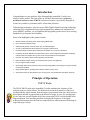
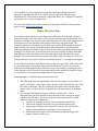
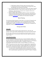
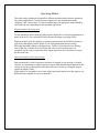
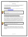
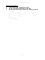
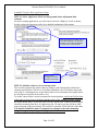
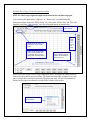
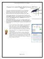
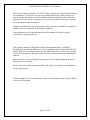
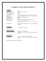
Armadillo Crossfire Side Fire Traffic Collector User Manual and Installation Guide Rev 1.0, 1st March 2014 Armadillo Crossfire Non-Intrusive FMCW Radar Based Traffic Collector Houston Radar LLC 12818 Century Drive, Stafford, TX 77477 Http://www.Houston-Radar.com Email: [email protected] Contact: 1-888-602-3111 This device complies with part 15 of the FCC Rules. Operation is subject to the following two conditions: (1) this device may not cause harmful interference, and (2) this device must accept any interference received, including interference that may cause undesired operation. Changes or modifications not expressly approved by the party responsible for compliance could void the user's authority to operate the equipment. Any modification or use other than specified in this manual will strictly void the certification to operate the device. Unit emits low power microwave radar signals through the front cover. Do not cover with any labels or block for proper operation. Keep unit powered off when not in use. Note: Specifications may change without notice. Note: Not liable for typographical errors or omissions. Table Of Contents INTRODUCTION............................................................................................................. 5 PRINCIPLE OF OPERATION ....................................................................................... 5 FMCW RADAR ................................................................................................................ 5 RADAR DETECTION ZONE ................................................................................................ 6 RADAR POINTING ............................................................................................................. 7 BACKGROUND CLUTTER .................................................................................................. 7 Clutter Map ................................................................................................................. 7 Clutter Map Time Constant ........................................................................................ 7 Choosing a CTC value ................................................................................................ 8 OPERATING MODES ......................................................................................................... 9 Highway mode (side firing only)................................................................................. 9 Intersection mode (side or front firing) ...................................................................... 9 USER CONFIGURABLE DETECTION LANES ..................................................................... 10 Lane Definition ......................................................................................................... 10 Lane Status over USB ............................................................................................... 10 Lane Setup ................................................................................................................. 10 Historical Lane Counts ............................................................................................. 10 STREAMING ASCII DATA .............................................................................................. 10 RADAR MOUNTING ........................................................................................................ 11 Side firing installations ............................................................................................. 11 Mounting Bracket...................................................................................................... 11 Location .................................................................................................................... 11 Setback and Mounting Height ................................................................................... 11 Sighting Camera ....................................................................................................... 12 INITIAL SETUP ................................................................................................................ 14 Selecting an Operating Mode ................................................................................... 14 Selecting Clutter Time Constant and Performing Clutter Initialization................... 14 Defining Lanes .......................................................................................................... 14 Optimal Performance Checklist ................................................................................ 15 Armadillo Crossfire Basic Application Setup ........................................................... 16 PD300/PD310 Target Verification and Lane Setup ................................................. 17 In-Radar Lane-By-Lane Counts................................................................................ 22 CONNECTING TO THE ARMADILLO TO RETRIEVE DATA ........................... 23 RETRIEVING DATA USING THE USB INTERFACE: ............................................................ 23 RETRIEVE DATA USING THE BUILT IN BLUETOOTH WIRELESS INTERFACE: ..................... 23 IMPORTING DATA ...................................................................................................... 23 ANALYZING DATA ...................................................................................................... 24 CHARGING THE BATTERY ...................................................................................... 24 CHARGING VIA THE FAST AC CHARGER (RECOMMENDED) ........................................... 25 CHARGING VIA USB ...................................................................................................... 25 CHARGING VIA THE OPTIONAL BUILT-IN HIGH PERFORMANCE MPPT SOLAR CHARGER ....................................................................................................................................... 26 ARMADILLO CROSSFIRE SPECIFICATIONS ...................................................... 28 GENERAL ....................................................................................................................... 28 APPROVALS ................................................................................................................... 28 DATA INTERFACES ......................................................................................................... 28 MECHANICAL ................................................................................................................. 28 Introduction Congratulations on your purchase of the Houston Radar Armadillo Crossfire nonintrusive traffic counter. This state of the art 24GHz K-band microwave frequency modulated continuous wave (FMCW) radar based counter is specifically designed for license free portable or permanent traffic volume data collection. Utilizing high performance, ultra-low power DSP (Digital Signal Processing) technology and microwave components based on a planar patch array antenna with integrated low power PHEMT oscillator, you will find that this high quality product meets your exacting standards for performance and reliability. Some of the highlights of this product include: World’s smallest and lowest power usage ranging FMCW radar. Up to 105ft (32m) detection range Simultaneously detects, tracks and logs up to six individual targets. Six user-configurable lanes allow assignment of targets to specific lanes. Unmatched range resolution allows setting lane boundaries in 1 foot (0.3m) increments. Companion Windows application provides intuitive GUI to set all configuration parameters and display real time plots of the targets, lane by lane counts and accumulated count histograms. Firmware “boot loader” allows for field upgrading of the firmware. Built-in statistics storage memory for stand-alone lane-by-lane count gathering. FCC pre-approved with CE mark. Optional high performance maximum power point technology (MPPT) solar charger to long term studies or permanent locations Optional GPS option to geostamp data collection location (coming soon). Optional 3G modem for remote data access. (Coming soon. Annual data plan subscription required). Principle of Operation FMCW Radar The PD310 FMCW radar in the Armadillo Crossfire modulates the frequency of the transmit signal in a linear fashion. The difference between the frequencies of the local oscillator and the signal returned from the target is proportional to the time delay between these signals and thus is proportional to the distance to target. In case of a moving target we also take into account Doppler shift of the return signal. PD310 utilizes double linear ramp modulation, first increasing and then decreasing the frequency of the signal. Additional information derived from two ramps allows the radar to measure both range to target and target velocity. The Armadillo Crossfire employs advanced target tracking technique based on a proprietary algorithm that allows it to detect, measure and track multiple targets simultaneously. It also features advanced “application filters” pre-configured to optimize performance for a variety of applications. For a more detailed theoretical description of the principles of FMCW radar operation please see this article on the Internet. Radar Detection Zone The radar detection zone has an oval shape and is defined by the beam cone (20ºx60º) and incident angle to the road surface. Note that the beam does not cutoff abruptly at the boundary of the detection zone but rather gradually tapers off. Thus weak targets near the boundaries may be missed while strong targets outside may still get detected. The strength of the target is determined by its radar cross-section (RCS) and depends on the target material, area, shape and incident angle of the radar beam. Large flat metallic surfaces positioned at exactly 90 degrees to the incident radar beam make the best targets. Examples are vehicle sides, front and rear ends. Flat metal surfaces at angles other than perpendicular to the beam tend to reflect the radar signal away and reduce the signal strength. Two or three metal surfaces joined at 90 degree angle, for example a corner of a pickup truck bed create perfect reflector and usually result in a very strong return signal. As the radar beam diverges with distance the detection zone gets wider. This can be used to a great advantage if you need to increase the detection area. In this case, move the radar away from the target location. This may involve, for example, mounting the radar on the opposite side of the road or increasing setback and/or height. This kind of a setup is often used in a loop-replacement application for intersections. Important things to remember about radar detection zone: 1. The radar beam does not end abruptly at the specified angle. Per convention, we specify “half-power” beam angles where the power falls off to half the value from the center of the beam. Thus it is possible for the radar to detect strong targets outside of the oval derived from a trigonometric calculation based on the beam angle. 2. Every target has different microwave reflective characteristics. This is characterized by the RCS and affects how much microwave energy the target returns back to the radar. This is one of the most important factors in reliable detection. Simple rules of thumb are: a. Vehicle side typically has larger cross section than vehicle front b. Vehicle rear typically has larger cross section than vehicle front c. Larger target is likely to have larger RCS, thus a truck will provide a stronger return signal then a passenger car or a motorcycle. d. Metal targets have larger cross section than non-metallic targets (like humans, animals, plastics etc.) e. Metal surfaces joined at a 90-degree angle create perfect reflector. f. Perfectly flat metal surface at an angle other then 90 degrees may reflect the radar beam away and result in a weak target. 3. In a side firing configuration as the vehicle passes in front of the radar, an incident angle momentarily becomes 90º and results in a strong return signal. This effect manifests in a somewhat narrower detection zone compared to what may be expected from the beam geometry. 4. Unlike in a Doppler radar, with FMCW radar there is always a fixed internal design limit to the maximum detection range. No matter how strong the target is, it will not be detected beyond this limit. The maximum detection range may be found in the specification and is different for various modes of operation. Radar Pointing The radar beam should be pointed across the traffic at 90º to the road. Pointing the radar at an angle substantially different from 90º is not recommended because the signal strength is severely reduced. The industry refers to pointing the radar at 90º as a side firing installation. Consult Operating Mode section about what types of installations are supported by current firmware. Background Clutter Clutter Map Since the radar can detect stationary targets, things like fences, road curbs, lane separators, traffic signs and other unwanted targets need to be processed and eliminated from the output. In order to do so the radar maintains a clutter map where it stores all these unwanted targets. The clutter map is subtracted from the signal leaving only true targets to report. Clutter Map Time Constant The radar continuously adjusts the clutter map to account for changing conditions. The rate of the adjustment is determined by clutter time constant (CTC). CTC specifies how long does it take for an average target to fade away into the background, e.g. become part of the clutter map and no longer be reported as a valid target. CTC is a user programmable value and can be set from 1 second to 28 minutes. For a fast moving traffic CTC may be set to a lower value whereas for a stopped traffic it is appropriate to set it to a higher value. Besides automatic continuous adjustment of the clutter map, the user can issue a command to take and store a quick snapshot of the current clutter map and use it as a new basis the next time the radar is turned on. Typical use cases are: 1. You may issue this command during the setup when road is clear of the vehicles so you do not have to wait for an automatic clutter map adjustment to take place. This is especially handy in applications where a long CTC is required. A snapshot command temporarily overrides long CTC value and speeds up clutter map reconstruction. 2. You want the radar to start with a “mostly good” clutter map after the power cycle in order to reduce initial adjustment time. The clutter map adjustment rate is asymmetric. The clutter is adjusted up slowly (targets fade away slowly) but is adjusted down fast. This facilitates improved clutter map maintenance in situations where traffic density is high. You MUST issue the “Initialize Clutter” command via the provided GUI after you have setup the radar in the intended location. You MUST reissue this command if you change the operating mode of the radar, as the clutter map will be considerably different. You MUST reissue this command after you adjust the radar pointing, height or angle on the road. Choosing a CTC value Typically you would set the CTC value to be 5 to 10 times longer than the maximum expected presence time of real targets. Settings the CTC to too short a value may result in real targets fading into the background thus resulting in poor detection. Typical CTC values are 15 seconds to 5 minutes for highway mode if vehicles are not expected to stop in front of the radar for extended periods of time. Typical CTC values are 10 to 30 minutes for intersection mode where vehicles may be expected to stop in front of the radar for a few minutes at a time. Operating Modes The radar can be configured to function in different operating modes that are optimized for various applications. Current firmware supports two pre-programmed modes: “Highway” and “Intersection”. For the best performance an appropriate mode should be selected by the user depending on their intended application. Highway mode (side firing only) To take advantage of this mode the radar must be deployed in a side firing installation so that it looks across the road and NOT directly into incoming or receding traffic. Highway mode is used for counting, occupancy measurements and vehicle detection at typical city and highway traffic speeds. It can easily distinguish between closely following individual vehicles in multiple lanes. Traffic is expected to be free flowing most of the time. If traffic does slow down and come to an occasional stop, it is acceptable for the radar to experience brief signal dropouts as the vehicle moves across the detection zone. Intersection mode (side or front firing) Intersection mode is used for presence detection of stopped or slow moving (<14mph) vehicles. It is optimized to continuously track targets with minimal signal dropouts as the vehicle slowly moves through the radar detection zone or comes to a complete stop for significant length of time. In this mode it is acceptable to miss some of the high speed targets since they appear very different from a stopped or slow moving traffic. Houston Radar PD300/PD310 User Manual User Configurable Detection Lanes Lane Definition A lane is a user-configurable range slot within the radar’s detection zone. When a vehicle is present within this slot, the lane gets “activated”. Lane activations are used for presence indication whereas vehicle tracking is used for counting. For example if a vehicle has crossed from lane to lane it will be counted once only but both lanes will be sequentially activated. Lane Status over USB Target presence information in each lane (lane activation status) is also available in realtime to an attached controller via the USB port. An external controller communicates with the radar via the Houston Radar Binary protocol. The same protocol is used to communicate to all radars (Doppler and FMCW) produced by Houston Radar. Please contact us for a “C” or “C#” SDK (software development kit) if you wish to utilize this feature. Lane Setup Typically, you would configure one or more detection lanes during initial setup. Please note that the radar measures distance along the line of view from the radar to the target and does not correct for the mounting height. This is usually not a problem as the supplied configuration program accumulates and displays all detected targets as a histogram in real time regardless of lane setup and the user may simply draws the lane boundaries around the histogram peaks. Thus no manual calculations are required. Historical Lane Counts The radar also counts the number of vehicles detected in each lane during every accumulation interval. Accumulation interval is programmed in minutes via the “Record Interval” setting on the configuration tool. These counts are stored in internal memory and may be retrieved later for analysis. Streaming ASCII Data In instances where a user only needs to know only counts and/or occupancy indicators on periodic real time basis, and can remain connected to the radar, the Crossfire may be configured to stream counts per lane and occupancy indicators per lane periodically. In order to enable streaming occupancy indicator per lane check the “Periodic ASCII Output” checkbox(s) in the Radar Setup tab of the configuration tool. Page 10 of 28 Houston Radar PD300/PD310 User Manual Radar Mounting Side firing installations Typically the radars will be used in a side firing installation where the radar points across the traffic, e.g. radar beam is at 90 degree angle to the road and covers one or more lanes. This mode must be used to detect traffic at typical highway speeds. It may also be used for intersection and stop bars to detect stopped or slowly moving traffic. In this mode vehicles traveling on the road at highway speeds are detected for a short duration of time while they are crossing the beam and their velocity is mostly tangential (at right angle to the beam) with a negligible radial (along the beam) component. Mounting Bracket The provided mounting bracket allows for sufficient adjustment of the radar pointing angle for various mounting heights. The user must perform a “camera view” check using the included snapshot camera to validate that the radar beam is pointed correctly. Installation must also ensure that the Armadillo Crossfire is rigidly mounted. Support structures that are affected by wind are not a good choice. Swaying action changes radar’s field of view and affects the performance. Note: highway mode is less susceptible then intersection mode due to lower sensitivity and range resolution. Location Places that have a lot of wall area such as tunnels and overpasses are not a good location for the radar. Walls can bounce the radar beam and create ghost targets. Note: when beam bounce or multi-pass propagation creates ghost targets it is sometimes possible to adjust the radar location in such way that these ghost targets would fall outside of the user defined lanes and thus be discarded. Supplied Windows Configuration Utility should always be used to verify the setup. Setback and Mounting Height In the side fire multi-lane installation the radar must be mounted in such way that it may see over the top of the closer vehicles. This requires it to be mounted higher than the tallest vehicle it will encounter in a closer lane. An exception to this rule is a situation where you are detecting only the closer lane, e.g. a turn lane or an exit only. In which case the radar can be mounted at target height and pointed horizontally. This may also be used in locations with very low traffic density where the probability of simultaneous vehicles in adjacent lanes is very low. Page 11 of 28 Houston Radar PD300/PD310 User Manual For optimal performance, the setback must be increased with the mounting height as suggested in the table below. Insufficient setback may result in lane misdetection for the closer lanes. Radar pointed down between one-third and one-half of the detection zone Acceptable range of pointing variation. Height Ln 1 Ln 2 Ln 3 Ln 4 Ln 5 Ln 6 Setback Armadillo Crossfire Setup Table Number of 12 Minimum Setback (ft) feet (4m) lanes Highway/Intersection 11 6 2 10 3 13 4 15 5 17 6 20 Minimum Setback (m) Highway/Intersection 1.8 3.0 4.0 4.6 5.2 6.1 Minimum Height (ft) 4 17 17 20 21 23 Minimum Height (m) 1.2 5.2 5.2 6.1 6.4 7.0 Sighting Camera The Armadillo Crossfire has an inbuilt color VGA sighting camera. You may take a snapshot via the supplied configuration tool and examine the view of the camera that approximately matches the view of the radar. This makes verifying the pointing quite simple and convenient. 1 In intersection mode when detecting only one closest lane the setback requirement can be reduced to 4 feet (1.2 m) Page 12 of 28 Houston Radar PD300/PD310 User Manual An example photo from the Armadillo Crossfire sighting camera showing proper pointing for a 4 lane highway. In the example photo above note that the 4 lanes are approximately centered in the frame and the radar is mounted high enough and with enough setback to allow an unblocked view of traffic in all lanes. In this example, the Armadillo Crossfire was mounted with a 20 foot setback from the closest lane and about 20 feet high. The far lane is about 88 feet away. Click the “Take Photo” button to take a snapshot of the radar view of the road. This is a very convenient feature of the Armadillo Crossfire to verify proper pointing both in the vertical and horizontal direction. Ensure you are pointed as close to 90° to the passing traffic as possible for best results. The photo is also saved in the stats analyzer database and you can later view it once you import the data from the unit. Page 13 of 28 Houston Radar PD300/PD310 User Manual Initial Setup You must initially configure the radar for your intended application at the installation site to ensure proper operation. At least an appropriate application mode and clutter time constant should be selected, clutter map initialized and lanes defined. Selecting an Operating Mode Use provided Windows Configuration Utility to set an appropriate mode of operation as recommended in Operating Mode section. Use Highway Mode where precise counting of the vehicles is important. Use Intersection Mode where reliable detection of the stopped or slow moving traffic is important Selecting Clutter Time Constant and Performing Clutter Initialization Use provided Windows Configuration Utility to set clutter time constant (CTC). Clutter time constant should be 5-10 longer than the maximum expected duration of the stopped traffic. For example if a vehicle stops in front of the traffic light for a maximum of 1 minute, CTC should be set to 5-10 minutes. After the time constant is set, wait for clear road and initialize clutter map. Clutter map initialization takes 15 seconds. Occupancy should be low during this time. Clutter map initialization is not absolutely required. Without initialization it will take the radar about ten CTC to initialize the clutter map on its own and start operating normally but this delay will occur after every power cycle. Clutter map must be re-initialized after switching between highway and intersection mode and after adjusting radar pointing, height or location. Defining Lanes Use provided Windows Configuration Utility to define lanes. If lanes are not defined, counts, occupancy and lane activation features will not operate correctly. If open drain outputs are used, make sure they are correctly mapped to lanes. You only have to define lanes that you are interested in, other lanes may be omitted and radar will disregard traffic in those lanes. Page 14 of 28 Houston Radar PD300/PD310 User Manual Optimal Performance Checklist Tunnel and under overpass locations should be avoided. The radar should be rigidly mounted to minimize wind action. Radar should be pointed across the direction of traffic (side-firing) so that the side of passing vehicle is visible to the radar and vertical angle adjusted to cover all configured lanes. Radar should be mounted high enough to “see” over the top of the highest expected target. At least 17 feet of height is recommended in case of truck traffic. This requirement increases as you try to detect far lanes. Operating mode of the radar (highway or intersection) must match intended application. Appropriate background clutter compensation time constant must be selected and clutter map initialized. Lanes should be configured and stored in the radar. Page 15 of 28 Houston Radar PD300/PD310 User Manual Armadillo Crossfire Basic Application Setup STEP #1: Select Application Mode and background clutter adjustment time constant. For most counting applications, you will want to select the “Highway” mode as shown. See the section on clutter map earlier for a detailed explanation of this setting. After connecting to the radar, click on the PD300 Setup tab. The GUI will read the current radar configuration and allow you to edit and save it. Click on “Save Changes” to save the settings to the PD300. STEP #2: Initialize clutter to correct startup value. The Crossfire continuously adjusts clutter to changes in the background with the time constant specified above. However, to facilitate immediate view of real time targets and lane setup, it’s advantageous to set the initial clutter level to eliminate fixed targets when no real targets are present in the radar’s view. To do this, ensure radar is securely mounted in desired position, wait for the field in front of the radar to clear of any real targets and then click on the “Initialize Clutter” button in the screen shown above. If you now click over the “PD300 Plot” window, no new targets should be streaming from the x=0 (right most) side. Of course you may still have older targets showing on the plot but they will scroll off eventually off the left side of the chart. You should re-initialize clutter if you make any changes to the radar mounting (height or angle) or operating mode (Highway or Intersection). Page 16 of 28 PD300/PD310 Target Verification and Lane Setup STEP #3: Check target signal strength and location on the real time range plot. After selecting the application (“Highway” or “Intersection”) and initializing the background clutter map in the PD300 Setup Tab, click on the “PD300 Plot” tab. This will bring up a real time “chart recorder” type plot of tracked targets as shown below. Select the “PD300 Plot” window. Target linear range from face of the radar. Select how much history (in seconds) is shown on the chart. Past (t = now -10 seconds). This is what the radar “saw” 10 seconds ago. You may change this in the box above. Present (t=0) seconds. This is what the radar is “seeing” at this instant in time in front of it. PAST HISTORY. Time in seconds Please review the layout of the real time range plot above. All targets the radars detects in front of it will be shown here as red lines. The actual real-time range is plotted. Every red line is a target that is tracked by the radar. The plot keeps track of a specified amount of history before targets are allowed to scroll off the left part of the screen. Right click to access more options. Check Target Signal Strength: A very weak target. Only 5 empty RSS bars. Will be first to fade away into background clutter. Targets are plotted in real time as red lines and scroll from the right to the left. Long lines as shown represent stationary targets (this plot was taken inside a room. Some of the top targets are double reflections from walls and corners). Check “Show RSS” to show the target Receive Signal Strength. 3 or more solid bars out of 5 represent a good signal. You should adjust the radar pointing to get 3 or more bars to the desired target(s). Range can be read off the scale on the right. Alternatively click on the target for a range reading on your screen or right click to access plot zoom features to get a more accurate reading. Typical Real Time Chart Recorder View of “Intersection Mode” Five targets are shown and are stationary in this view since horizontal target lines means distance to target is not changing over time. You may enable histogram to show all observed targets stacked up on the left. This will provide better statistical data for lane configuration. You should also enable the “Show RSS (received signal strength) checkbox to view the signal strength of the return signal from the visible targets. For every target detected the histogram grows by one pixel when the target is no longer being tracked. Stationary targets will meld into the background clutter and disappear from view with the “Background Clutter Compensation” time constant. Thus it’s very important to set the clutter time constant to a value that is at least 5 to 10 times longer than the normal expected presence time of targets in front of the radar. Excellent return signal strength from this vehicle on the road. Enable “Show Histograms” to observe where targets are appearing on the range plot. This will help you define lanes. Typical Real Time Chart Recorder View of “Highway Mode” Targets observed in the last 5 seconds (this is user set in the box on the top left) show up as red tracks while older targets that have already scrolled off the screen are contributing to the height of the blue histograms on the screen left. As can be clearly seen from the histograms, traffic has created four clearly defined groups. Each group corresponds to a lane on the four-lane highway. Defining lanes is as simple as drawing them around the histogram peaks as shown in the next section. Also note excellent signal strength from each of the shown targets. Each red track (a target) has at least 3 or more filled “RSS” bars. Lower signal strength may indicate a problem with radar installation and pointing. Typically, for a given target length and speed, further targets will result in longer tracks due to the beam diverging as it propagates away from the radar. This can be seen on the example screen shot above. Similarly, faster targets, all other things being the same, will result in shorter tracks. Note: The scrolling speed of the target lines is based on the amount of history you select to view. It is not an indication of the speed of the target. Additionally, the Armadillo Crossfire cannot determine direction of travel of the target. Thus by default the targets will always scroll from the right (present) to the left (past). Armadillo Crossfire Live Lane Setup Step-By-Step Example: Real targets are streaming by. Setting up lanes is as easy as drawing around them on this chart. Right click on chart background to access lane setup context menu. Then select either “Define new Lane” if no lanes are present or “Edit Lane(s)…” if lanes have already been defined and you need to adjust the start/end positions. You can also draw around the built up histograms that show you where the targets are occurring. Place first boundary around histogram by left clicking the mouse button, then place second boundary. Lane is now defined between these two boundaries. Once stop boundary is defined, lane will fill with gray. As you move the boundary location before placing it, you can see the distance from the radar face. This is the direct distance from the radar to the target and not the horizontal distance on the road. Once you place the lane boundary, it will be rounded to the nearest foot as lane boundaries can only be specified in integer number of feet. Armadillo Crossfire Live Lane Setup Step-By-Step Example Continued… This road has 4 lanes (gray) with a median in between (white). Even though targets (sometimes double reflections or a curb or a lane divider) may be detected as red line in the median, they will not affect lane counts or other lane based data collected by the radar or trigger digital outputs. You can adjust the lane locations, add or delete a lane) by right clicking and selecting “Edit Lanes…” and bringing up this window. To match the direction of the traffic, you can split the screen in two in the center and start drawing some lane on the right side of the split to scroll the other way (left to right). T=0 (now) then becomes in the center as shown here. Note: This is a display feature for convenience only and does NOT affect the radar at all as the radar cannot determine traffic direction in side-fire mode. If you wish this lane to scroll from center split to right, draw the lane by clicking on the right side of the split. The target will then appear on the right side of the line and scroll right to match the direction of traffic. When screen is split, t=0 (now) is in the center where the split is shown. In-Radar Lane-By-Lane Counts The Armadillo Crossfire keeps date/time stamped accumulated counts of vehicles in each lane and periodically save off this data in internal non-volatile memory. The radar has a 20x60 degree beam angle for best count accuracy. This minimizes the merging of the target return signal of closely following vehicles in far lanes where the radar beam has diverged past the width of a typical car. There is adequate memory to save the last 4+ months of data. After that the log will roll over and start overwriting the oldest data. On a typical road with a free flowing traffic, the Armadillo Crossfire can be better than 98% accurate on a lane-by-lane basis and better than 99% accurate on a direction basis. For best accuracy, the radar should be setup in highway mode and traffic must be moving faster than 7mph (11kph). The range plot can keep track of counts on a lane-bylane basis to assist you in comparing with actual counts on the road. Note: These are not the counts logged by radar in internal memory, but counts kept by the PC program after it has established connection to the radar. The Real Time Range Chart Recorder Plot has a helpful “counts per lane” feature that you can use to verify the accuracy of lane-by-lane counts during initial setup. Connecting to the Armadillo to Retrieve Data There are two ways to connect to retrieve data from the Armadillo: Retrieving data using the USB interface: 1. Connect the provided cable to the weatherproof connector on the bottom of the box and tighten to secure the connection. Plug the USB connector on the other end in a USB slot on a Microsoft Windows computer. 2. Power on the Armadillo. Windows will detect a USB to RS232 converter and install a COM port. If your computer is connected to the Internet it will automatically install the drivers. Otherwise drivers are located on the provided CD ROM in the USBdrivers folder. When connected to the USB port or USB charger, the stats box will also slow charge the internal battery and supply power to the Armadillo in the case of a depleted battery. USB and Charger Connection Retrieve data using the built in Bluetooth wireless interface: You must have a Bluetooth adapter on your computer to make a Bluetooth connection. Bluetooth is indicated by the icon in the task bar. A Bluetooth Class I USB adapter is provided. We highly recommend using the provided Class I USB Bluetooth adapter even if your computer has a built-in Bluetooth adapter. Built in adapters are usually 10m range Class II adapters and will only allow a connection if you are next to the box. The Armadillo has a high performance very long range Class I adapter that will perform best when paired with the provided Class I adapter. If you have previously paired your computer’s Bluetooth adapter with the Armadillo, you can skip to the next section. If this is the first time you are connecting to this particular box, you must first pair the two Bluetooth adapters. 1. Open the Bluetooth interface on your computer by clicking on the icon and then scan for devices (or click on “Add a device”). All Houston Radar Bluetooth device names start with “HR-BT“ and the complete and unique name is also printed on the box. You must pair once with each Armadillo from your PC. 2. Once the scan locates the Armadillo, right click and select “pair” and establish the connection. Windows will then assign a COM port to this paired connection. A pairing key is not required but in case it is requested, enter 1234. The Bluetooth interface in the Armadillo is not operational if its USB port is plugged in to a computer. It is not affected by the AC fast charger or a dedicated USB charger. Importing Data 1. Start the previously installed “Houston Radar Stats Analyzer” and then go to Data->Data Import Wizard… Houston Radar PD300/PD310 User Manual 2. Select “Import From Radar…” option. 3. Drag and drop the data from the pane on the right a project on the left (you can right click to create a new project). If you have more than one 4. Once the traffic stats are read you may choose to erase the data memory. This will avoid the same data being imported next time. 5. Click on OK at which point you may enter a name for this location. 6. Analyzing Data Please refer to the Houston Radar Advanced Stats Analyzer user manual (supplied as a PDF file) on the provided CD ROM for a detailed tutorial on analyzing the data. The latest version of this file is always available on our website at: http://www.houston-radar.com/user-manuals/HoustonRadarAdvancedStatsAnalyzerUserManualRelease.pdf Scan the QR code with smart phone to download manual in pdf format. Page 24 of 28 Houston Radar PD300/PD310 User Manual Charging the Battery The Houston Radar Armadillo features a state-of-the-art Lithium Iron Phosphate (LiFePO4) battery that will allow the unit to run at least one week on a full charge. Additionally it will retain the charge for many weeks when switched off and placed on the shelf, thus being ready when needed. You must fully charge the battery once initially using the provided fast AC charger for the on-board fuel gauge to work properly. There are 3 methods to charge the battery: Charging Via the Fast AC Charger (recommended) Connect the provided fast charger to the black connector on the weather proof cable provided with the product and plug the circular connector into its mate on the bottom of the box. Plug the AC charger into a 110 to 240V AC wall socket. Ensure that the light on the quick charger turns on. A red light means that the battery is charging. A green light means that the battery is fully charged. Fast AC Charger Connector A fully depleted battery will take about 3.5 hours for a full charge. You may also monitor the percentage charge via the Houston Radar Stats Analyzer. Connect to the Armadillo and go to File->Connect To Radar… and click on “Connect To Radar”. Once connected, a battery icon will be shown in the window. The charging status is shown via a blinking thunder bolt and the percentage charge remaining is listed next to the battery icon. Battery Charge Status Icon Charging Via USB 1. Connecting to a powered USB hub (any desktop USB port and most notebook USB ports) will charge the battery at the rate of about 1.5Watt/Hour. This will take about 2 days for a full charge and is recommended only for a quick top off. 2. Connecting to an AC powered high power USB wall charger will allow the battery to charge with as much power is available from that source. You can typically purchase a charger in the open market with an output current of 1 or 1.8A. This will provide about 3.3Watt/Hour or 6Watt/Hour respectively. This will charge the battery in 11 to 19 hours. 3. Plug the USB connector into the 12VDC car adapter provided with the unit. This will charge the battery at 1.8A and is convenient for a quick top off while in your vehicle out in the field. The unit will not charge from an Apple wall USB charger as those chargers do not follow standard the USB high power charger specification. The unit will usually charge from high power USB chargers of other smart phones and tablets (e.g. Android and Samsung etc.) as these typically follow the USB specification. Page 25 of 28 Houston Radar PD300/PD310 User Manual Charging Via the Optional Built-In High Performance MPPT Solar Charger If you have purchased the solar kit option to use in a permanent installation, connect the provided 10W solar panel to the solar panel circular connector on the bottom of the box. This will provide full autonomy in practically all locations even in winter. In the northern hemisphere, the solar panel must be pointed towards true South (not magnetic south) and angled based on the latitude of the location. Most smart phones feature a compass that may be set to point towards true South. The suggested angle from the horizontal is (location latitude + 15º). The solar panel will charge the battery even with the key switch in the off position but you will not be able to connect to the Armadillo if the switch is off. To see a visual history of the Armadillo’s charge/discharge status, simply connect to the Armadillo via the Houston Radar Stats Analyzer and then click on the battery icon. A window will open that will track the charge status of the battery. It will also calculate the rate of charge or discharge of the battery. This is a very helpful tool when debugging charging issues. The Armadillo also logs the battery charge, voltage and ambient temperature every hour to internal data memory. These parameters are extracted when you retrieve the traffic statistics data from the Armadillo and may be plotted. This will allow you to ensure that the solar charger is keeping the battery adequately charged. Page 26 of 28 Recommended Solar Panel Angle Houston Radar PD300/PD310 User Manual This device complies with part 15 of the FCC Rules. Operation is subject to the following two conditions: (1) this device may not cause harmful interference, and (2) this device must accept any interference received, including interference that may cause undesired operation. The device must be located 20 cm or more from persons. The device must not be co-located with other transmitters. Changes or modifications not expressly approved by the party responsible for compliance could void the user's authority to operate the equipment. Any modification or use other than specified in this manual will strictly void the certification to operate the device. This product contains a rechargeable Lithium Iron Phosphate battery (LiFePO4). Charging must be performed indoors in a dry environment only by the provided LiFePO4 battery charger. Do not charge unsupervised or hidden from view. Do not expose charger to rain, water or moisture. Securely cap the connectors on the bottom when installing box outdoors. Battery must be recycled or disposed properly per local recycling regulations or may be returned to us for recycling. Do not crush, pierce, and incinerate product or the battery. Discontinue use immediately if any leaking occurs. Product contains no user serviceable parts inside. Do not attempt to open or repair. Doing so will void all warranty. Page 27 of 28 Armadillo Crossfire SPECIFICATIONS General Operating Band Occupied Bandwidth RF Power Output Antenna Beam Pattern Max Range Range Resolution Polarization Supply Voltage Power Consumption Battery Charger Operating Temp. K-Band 24.020 GHz to 24.230 GHz 5mW 20x60° 120 feet in Highway mode, 80 feet in Intersection Mode 0.375 inch in Highway Mode, 0.25 inch in Intersection Mode Linear Internal 6.6Ah LiFePO4 battery 0.25 W Supplied 2A 10.9V float voltage LiFePO4 charger -4F to +140F (-20C to +60C) Electronics designed and tested to –40C, battery is limited to above ratings Weatherproof Yes, NEMA 4X Polycarbonate enclosure with weatherproof connectors. Approvals Approvals FCC (TIAPD300), CE Mark Data Interfaces PC Communication Data & Power Connector USB device, Class I Bluetooth Provided cable with USB Connector and high speed charger connection. Mechanical Weight Dimensions approx. 4lbs (1.8Kg) with mounting bracket 6.73 x 4.76 x 3.15 in. / 170.94 x 120.90 x 80.01 mm without bracket Specifications may change without notice.