1
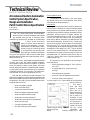
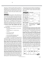
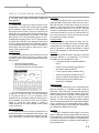
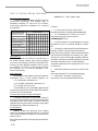
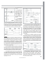
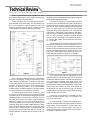
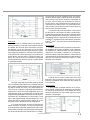
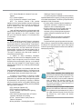
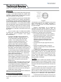
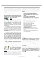
Technical
Review
Control System Design
A Condensed Guide to Automation
Control System Specification,
Design and Installation
Part 1: System Identification
and Safety
by Tom Elavsky,
AutomationDirect
If you have not been directly involved in the world of
factory automation, data acquisition, process instrumentation
or electrical controls in general, then the above words and
acronyms may be somewhat overwhelming. But these words,
and many others, are part of the language that's used in the
industrial automation world. (For "A Guide to Common
Automation Terms" refer to http://support.automationdirect.com/docs/glossary.html.)
The following is Part 1 of a four-part series of articles
on Control System Design that can act as a general guide to the
specification, design and installation of automated control
systems. The information and references are presented in a
logical order that will take you from the skills required to
recognize an operation or process suited for automating, to
tips on setting up a program, to maintaining the control
system. Whether you are an expert or a novice at electrical
control devices and systems, the information presented should
give you a check list to use in the steps to implementing an
automated control system.
Electrical control systems are used on everything from
simple pump controls to car washes, to complex chemical
processing plants. Automation of machine tools, material
handling/conveyor systems, mixing processes, assembly
machines, metal processing, textile processing and more has
1-1
increased productivity and reliability in all areas of manufacturing, utilities and material processing.
You may have come to realize that an operation or
process used to produce your end product is very laborious,
time consuming, and produces inconsistent results. You may
have also visualized ways that would allow you to automate the
operation. Automating the process will reduce the amount of
manual labor, improve throughput and produce consistent
results. You may have the skills to develop the mechanical
means and select the appropriate equipment to make this
happen, and although you have a basic understanding of electrical control devices, you may not have the experience to put
it all together. Your first option may be to enlist the help of a
qualified System Integrator. If you do decide to use a System
Integrator, it would be beneficial to understand as much as
possible about automation control system devices and their
terminology so that your communications with the System
Integrator go faster and more smoothly.
In most cases, special expertise is required to design and
install industrial automation control systems. Persons without
such expertise or guidance should not design and install
automation control systems because they can fail and cause
serious injury to personnel or damage to equipment. The
information provided in this series of articles is provided "as is"
without a guarantee of any kind. We do not guarantee that the
information is suitable for your particular application, nor do
we assume any responsibility for its use in your application.
It is our intent to produce this series of articles as a
usable guide, with additional information, including a typical
"real world" application that can be followed from concept to
completion. It is not our intent for the guide to cover every
possible topic dealing with automation control systems or to
even suggest that the topics being covered are fully detailed.
Instead, the topics are aimed at giving the reader a good
starting reference for automated control systems.
In Part 1, we will cover the topics of Safety and
Identifying an operation or process that could benefit from
automation. In upcoming issues we will cover control device
specification, control system design and construction, control
system installation, and finally control system maintenance.
The topics will be broken down as follows:
Part 1 - SAFETY and IDENTIFICATION
Part 2 - SPECIFICATION
Part 3 - DESIGN and BUILD
Part 4 - INSTALL and MAINTAIN
Safety:
The first and most important item to
consider before attempting an automated
control system, or even a simple on/off control
for a pump, is safety, both for personnel who
may be working with or near the automated equipment, as
well as to prevent damage to the equipment.
To minimize the risk of potential safety problems, you
should follow all applicable local, state and national codes that
regulate the installation and operation of your control system,
along with the equipment or process it is designed to control.
These codes vary by area and usually change over time. It will
be your responsibility to determine which codes should be
followed and to verify that the equipment, installation,
and operation is in compliance with the latest revision of
these codes.
Most likely your control system will be dealing with
electrical energy, so your first goal will be to eliminate the risk
of fire and electrical shock to personnel. The top organizations
that provide applicable standards and codes are listed below,
but even before you get to this area of safety, it would be wise
to educate yourself as much as possible about electricity and
electrical equipment in general. A good understanding of basic
electricity, including DC and AC theory and practice, Ohm's
Law, etc. will go a long way in helping you understand the
various codes and standards. There are many good
publications and articles on the subject of basic electricity and
some local technical colleges offer courses covering subjects
dealing with basic electricity. Some even offer courses in
Programmable Logic Controllers (PLCs), which can be very
useful when dealing with automated control systems. Also,
many Web sites offer free tutorials covering basic electricity
and PLCs. It would be beneficial to have some understanding
of electronic devices, such as the operation of a transistor and
other solid state devices, as well as understanding of the use
and operation of electrical test and measurement instruments,
such as voltmeters, current loop meters, clamp-on amp
meters, etc.
At a minimum, you should follow all applicable sections
of the National Fire Protection Association (NFPA) fire code,
and the codes of the National Electrical Manufacturer's
Association (NEMA). There may also be local regulatory or
government offices that can help determine which codes and
standards are necessary for the safe installation and
operation of electrical control equipment and systems.
Please keep in mind that if the automated control system
you are developing needs to be accepted in the international
market, the National Electrical Code (NEC), as a publication
of NFPA, is being harmonized with the International
Electrotechnical Commission (IEC) (Web site: www.iec.ch/)
and the European Hazardous Location Ratings. For more
information, check the Instrument Society of America's (ISA)
Web site at www.isa.org. Additional resources on the subject
can be found at www.ul.com/hazloc/
Another area of safety that needs to be considered for
automated control systems is lockout/tagout procedures as
specified by Occupational Safety and Health Administration
(OSHA). "Lockout/tagout" refers to specific practices
and procedures to safeguard operators and maintenance
personnel from the unexpected energization or startup of
machinery and equipment, or the release of hazardous
energy during service or maintenance activities. In order to
have your control system make use of a lockout/tagout
procedure, the design should include the ability to shut off,
neutralize, or isolate any energy source, such as the main
electrical feed, but also any pneumatic, hydraulic or
mechanical energy storage device. The means to do this should
be considered in the initial design of the automated control
system. Additional information can be found on OSHA's Web
site at: http://www.osha.gov/SLTC/controlhazardousenergy/
There are many reasons why the electrical devices that
you will use in the design of your automated control system
should be listed, approved or registered with a testing laboratory. One reason is to ensure that the device meets standards
that will prevent failure that could lead to catastrophic results.
Another reason might be for insurance or compliance
purposes. One of the most specified and premier safety testing
laboratories is Underwriters Laboratories (UL). The most
applicable area of interest for control systems is UL's Standard
for Safety 508A. If your control system panel requires being
built to UL508A, then you will need to contract directly with
UL to become a UL508A panel builder or use an existing
UL508A panel builder. Additional information can be found
at: http://www.ul.com/controlequipment/devices.html
Compliance to UL508A for AutomationDirect products
can be found on our Web site at:
http://support.automationdirect.com/compliance.html
The following are other safety points to consider in the
design of your automated control system:
- Emergency Stop - The control system must provide a
quick manual method of disconnecting all system power to
the machinery, equipment or process. The disconnect device or
switch must be clearly labeled "Emergency Stop". After an
Emergency shutdown or any other type of power interruption,
there may be requirements that must be met before the
control system or PLC control program can be restarted. >>
www.automationnotebook.com
1-2
Technical
Review
Control System Design Continued
For example, there may be specific register values in the PLC
memory that must be established (or maintained from the state
prior to the shutdown) before operations can resume. There
may also be mechanical positions of equipment that have to be
moved or jogged to the proper position.
- Accidental Powering of Outputs - Do not rely on the
automation control system alone to provide a safe operating
environment. You should use external electromechanical
devices, such as relays or limit switches, that are independent of
any electronic controlling device, such as a solid state relay or
a PLC output module, to provide protection for any part of the
system that may cause personal injury or damage. These
devices should be installed in a manner that prevents any
machine operations from occurring unexpectedly. For
example, if the machine has a jammed part, the controlling
system or PLC program can turn off the motor rotating a saw
blade. However, since the operator must open a guard to
remove the part, you should also include a bypass switch that
disconnects all system power any time the guard is opened.
- Orderly Equipment Shutdown - Whether using a
control system designed around relays and timers or a PLC, an
orderly system shutdown sequence should be included in your
design. If a fault is detected, then any mechanical motion, valve
position, etc., needs to be returned to its fail-safe position and
the equipment/process stopped. These types of problems are
usually things such as jammed parts, broken cutting tools, bin
full, etc. that do not pose a risk of personal injury or
equipment damage. If a detected problem would result in risk
of personal injury or equipment damage, then use other means
to deal with it, such as applying a brake to rotating equipment
to stop it before personnel can come in contact with it.
- Grounding - To prevent electrical shock, incorporate
good grounding practices in the design, construction and
installation of your system. Use protective devices for faulted
conductors to prevent fire, and also realize that good
grounding practices can reduce electromagnetic and radiated
noise interference to sensitive electronic devices.
- Finger-Safe and Dead Fronts - Another safety area to
consider is the use of devices that have finger-safe terminal
connections, which are surrounded by insulated guarding. The
use of protective guards over live circuits should also be considered, even on control panels that have limited access, so it is
safer for maintenance electricians and authorized personnel to
troubleshoot or make adjustments to electrical control devices.
Dead fronts should be used on control system enclosures where
the operator needs to make adjustments to devices, such as
selector switches, thumbwheels, potentiometers, etc., and the
controls need to be inside the enclosure so as to protect them
from outside weather conditions. The dead front is normally
an interior door that is mounted in front of the main control
panel. The outside enclosure door may still require key entry
by the operator, but the dead front interior door with
adjustable devices is interlocked so that it requires a switch to
open it, disconnecting power to the electrical devices mounted
on the main control panel.
- Closed-loop Control - It is your responsibility in any
type of closed-loop control system to ensure that if the feedback signal is lost, the system shuts down so as not to cause
injury to personnel or damage to the equipment.
Identifying Process for Automation:
The first step in configuring an automated control system is to identify what
can be automated. You need to have a good
understanding of basic electricity and safety.
It is also important that you have an understanding of basic
hydraulics, pneumatics, mechanical operating mechanisms,
electronics, control sequences, etc. and a solid knowledge of
the operation or process that you are going to automate.
- Control Power Distribution - Develop a power
distribution scheme in the control system circuitry, according
to code, that ensures all circuits are protected with fusing,
circuit breakers or other interrupting means coordinated such
that only the faulted circuit will be opened (de-energized),
allowing other powered equipment and devices to continue
to operate.
You should understand how to control motion and
movement, regulate the flow of fluids, dispense granular materials, orient parts, sense product in position, detect when an
operation is complete, etc. As a simple example, let's say we
have a conveyor that moves our product from point A to point
B. The conveyor is powered by a 3-phase AC motor, which is
turned off and on by a manually controlled motor starter and
includes, for fire protection, both short circuit and overload
protection. The system requires an operator standing at the
motor starter to watch as the product reaches the entrance to
the conveyor, and to turn the conveyor on to move the
product. The operator must also turn the conveyor off once the
product has reached the discharge end.
- Unauthorized Access - Make sure all enclosures and
cabinets that have energized circuits are secured to prevent
unauthorized personnel from gaining access without the
proper tool, key or other authorized means.
To automate the conveyor, we will need to replace the
manually controlled motor starter with an electrically
controlled motor starter, including short circuit and overload
protection. We will need to size the motor starter to work
1-3
with the existing conveyor motor. (Refer to our Web site at:
http://www.automationdirect.com/static/specs/
fujimcselection.pdf for information on specifying
and sizing motor starters.)
We will also need to identify where to locate sensors such
as limit switches, photoelectric sensors, proximity sensors, etc.
that will indicate when an operation is completed. This is
required so our control system knows when to proceed to the
next step in our operation. As an example, we usually need a
limit switch to detect when a cylinder is fully extended, as in
the case when the cylinder is used to push our product onto a
conveyor. The cylinder "fully extended" signal is used to deenergize the solenoid valve that provided the air pressure to the
pneumatic cylinder. We also need a limit switch to indicate
when the cylinder has fully retracted, and provide a signal to
the start/stop control of the conveyor that the product push
cylinder is out of the way for the next product. Another application for a sensor is to indicate when the product has reached
the conveyor. The sensor can be a limit switch with a roller arm
that comes in contact with the product or a photoelectric
sensor that can detect the product by using an infrared beam of
light. The photoelectric approach may be the better choice
because the position of the product on the conveyor belt may
vary. (Refer to our Web site at:
www.automationdirect.com/static/specs/peselection.pdf
for information on selecting photoelectric sensors.)
We would continue with this analysis, looking at each
piece of equipment or component in our system, and select a
device that could control or sense it. Some examples include an
electrical solenoid valve to control water used to wash residue
from a product, or a pneumatic valve to control air pressure to
a cylinder operating a gate that diverts product on a conveyor,
or energizing a control relay to signal that a product is in
position on a scale.
In some instances we may need to vary the speed, rate or
position of our controlling device, such as varying the speed of
a conveyor, changing the amount a valve opens to control a
flow rate, or remotely changing the setpoint level for a tank.
This could be accomplished by using an analog output signal.
An analog output signal is a varying signal that corresponds to
the real value we have determined and calibrated into the
device. For example, a 0 to 10 VDC signal could represent a
conveyor speed of 0 to 500 feet per minute. An analog signal
to the speed controlling device for the conveyor motor of 5
VDC would result in a conveyor speed of 250 feet per minute.
Identifying devices to control motion, flow, events, etc.
and sensing completion is basically identifying the I/O (inputs
and outputs) of our control system. Once these devices are
identified, they can be used as the field devices in a PLC-based
system, or they can be “hard-wired” for simpler applications.
You will also want to determine if your automated
control system will benefit from the use of an operator
interface, also referred to as a Human Machine Interface
(HMI). If your process requires making changes to setpoint
values, process time, flow rates, etc., then the use of an HMI is
the best way to proceed. In these situations, you will most
likely need a PLC that can easily communicate with the
HMI device.
If your application requires keeping data records for
reference, traceability, history, trending, meeting regulations,
etc., then you should look at using a control system that would
fall into the category of a "Supervisory Control And Data
Acquisition" (SCADA) system. Most of these control systems
would be comprised of PLC-type I/O that interface to a PC
with appropriate software.
Part 2 will cover Control Device Specification.
References:
For information on "PLC Logic and Principles" by
Doug Bell of InterConnecting Automation, PLC training
books, and training through technical schools and
organizations visit:
http://support.automationdirect.com/docs/training.pdf
For Web sites with free tutorials that cover basic
electricity principles visit any of the following:
www.thelearningpit.com/elec/bas/theory/etb-menu.html
or http://www.kilowattclassroom.com/Index.htm or
http://www.mrplc.com/ or http://www.plcs.net/
You may also want to visit the AutomationDirect
Customer Forums at:
http://forum1.automationdirect.com/cgi-bin/Ultimate.cgi
Information for the National Electrical Manufacturer's
Association (NEMA) can be found at their Web site at:
http://www.nema.org. NEMA is also being harmonized with
the International Electrotechnical Commission (IEC) (Web
site: www.iec.ch/) and other European standards. Additional
information can be found at Global Engineering Documents'
Web site at: www.global.ihs.com. Global Engineering
Documents is also the source for obtaining NEMA, IEC and
CE documents.
Further information for the National Fire Protection
Association (NFPA) can be found at their Web site at
http://www.nfpa.org/. Some of the more useful publications
are the National Electrical Code (NEC), publication NFPA 70
and also as a good reference refer to the Electrical Standard for
Industrial Machinery, publication NFPA 79.
www.automationnotebook.com
1-4
Technical
Review
Control System Design
A Condensed Guide to Automation
Control System Specification,
Design and Installation
Part 2: Control Device Specification
by Tom Elavsky,
AutomationDirect
I
n Part 1 of Control System Design, we covered safety
aspects involved in the use of automated control systems
and discussed some tips used in identifying which
manufacturing equipment and processes can be automated.
In Part 2, we will cover how to
specify the various devices required for
controlling the equipment in an automated system. Your specifications need to
include not only the "controlling" devices
for your application, but also items such
as the housing or enclosure for the devices,
the type of wire required to meet the various codes, agency
approvals required for safety and insurance purposes, environmental conditions, etc.
As stated in Part 1, special expertise is generally required
to design, wire, install, and operate industrial automation
control systems. Persons without such expertise or guidance
should not attempt to design control systems, but should
consider seeking the services of a qualified system integrator.
Control systems can fail and cause serious injury to personnel
or damage to equipment. The information in this series of articles is provided "as is" without a guarantee of any kind.
With that said, the first skill we need to develop in this
effort will be the gathering of all the equipment parameters and
specifications needed to specify the devices required to control
the equipment. We need to be the proverbial detective who
would ask questions such as;
•
What is the operating voltage?
•
What is the power rating?
•
How much current does it draw?
•
What is the operating temperature range?
•
What is the relative humidity range?
•
What are the mounting dimensions?
•
What are the minimum mounting clearances?
•
What is the duty cycle?
•
How will the system be used?
•
Who will be using the control system?
2-1
Control System Devices
The devices you need to specify in your control system
will generally fall into one of three categories; input devices,
output devices and the processing unit.
Input devices
Input devices are used to sense a condition, detect movement or position, indicate a limit or set point has been reached,
sense intervention by an operator, detect an alarm, etc. Typical
input devices may include limit switches, photoelectric sensors,
pushbuttons, proximity sensors, an operator interface, etc.
These input signals are generally in an ON or OFF state. We
can look at an input from a device, such as a photoelectric
sensor used to detect an obstruction, and state that when the
sensor sees the obstruction, the sensor is ON; in other words
we have a true condition. When the sensor is not obstructed,
then the input is OFF; or we can say the condition is false.
These types of signals are called discrete signals, meaning they
are always one of two states; ON or OFF. They can be wired
into a PLC input module and the PLC can be programmed to
use the status of the signals to execute the logic to control the
automated system. Or these same signals can be used in a
"relay logic" system, where control relays are hardwired to
create the system logic.
Of importance to our specifications are the ratings of
these input devices:
•
What is the operating voltage; 24, 120 or 240 Volt
AC or DC?
•
If they are rated for DC, are they sinking or
sourcing?
•
What distances can they sense?
•
How much force can be applied to the actuator?
• How much current do they require?
As a note, most PLC DC input modules can be configured as
sinking or sourcing 1.
Also keep in
mind that when
selecting a sensor
device, such as to
detect the presence of
product or sense the
end of travel for a
mechanism, it is very
important to consider
the environment in
which the sensor will
operate. This should
Typical wiring for sinking Figure 1 not only include
temperature
and
and sourcing input
humidity ranges, but in some
devices
cases, indoor or outdoor use, altitude, ability for the sensor to
be washed down, etc. Photoelectric sensors are sensitive to the
atmosphere in which they can efficiently work. If there is a lot
of dust, dirt and/or mist in the air, then the optics can easily
become dirty or coated, reducing their sensitivity and operating distance.
Output devices
Output devices are used to control actions such as
motion, start/stop of equipment like conveyors and pumps,
on/off control of valves, operator alerts/prompts, status indications, etc. Typical output devices include relays, motor starters,
pilot lights, operator interface graphics and numeric display,
etc. These output signals, like input signals, are also discrete;
either ON or OFF. The signals can be wired from a PLC
output module to control the devices, such as starting and
stopping motors, energizing a valve to control water flow, illuminating a pilot light to alert an operator to a condition such
as "Bin Full", etc. Output signals can also be wired directly to
a controlling device using hardwired relay logic.
Of importance to our specifications are the ratings of
these output devices:
•
What is the operating voltage; 24, 120 or 240 Volt
AC or DC?
•
If they are rated for DC, are they sinking or
sourcing?
•
What is the current draw?
•
What is the duty cycle?
•
What is the operating temperature range?
• What are the mounting dimensions?
For example, if our process uses a solenoid valve to
control water flow to a wash station, we would need to know
the operating voltage of the valve and how much current it
draws. We also need to know not only the on-state current
draw of a valve, but also the inrush current, so that we can
properly specify a PLC output module or a control relay.
Although a valve may be rated to draw 250 mA continuous
current, it may have an inrush of 800 mA when first energized.
If an output module has eight output points and each point is
rated for 1 amp continuous duty, after thermal considerations,
the entire output module has a total rating of 6 amps and
therefore has a common fuse rated at 6 amps. If we had
solenoid valves connected to all eight output points and our
program called for them all to energize at the same time, the
total inrush current would be 8 times 800mA or 6.4 amps, and
most likely would blow the fuse. The solution could be to
select an output module with a higher current rating or to use
the ladder program to sequence the valves, preventing them all
from being energized at the same time. Another option is to
split up the valves between several output modules, using the
remaining points to power smaller loads such as pilot lights.
Certain output types may have derating curves depending on
the ambient temperature and the number of outputs energized.
Keep in mind that DC output modules can be sinking or
sourcing type.
The processing unit
All control systems
can typically be
defined as having
inputs, outputs and
some form of decision making going
on in between so
that the outputs are
controlled based on
the status of the
inputs. This brings
us to our third category, the "decision Typical wiring for sinking
Figure 2
making" element. and sourcing output
This element can devices
be performed by a
PLC, where we have inputs, outputs and a central processing
unit (CPU) that uses ladder logic programming to make decisions based on input status and the logical conditions in the
program (see figure 3). A similar device that can be looked at
in the same manner is a personal computer (PC). The
keyboard, mouse, scanner, etc. would serve as input devices
and the monitor, printer, speakers, etc. would be the output
devices. The microprocessor used on the motherboard, along
with its memory, the operating system, and the application
program would serve as the decision making element. As a
matter of fact, PCs are used in some automated control systems
as the decision making element, together with industrial input
and output (I/O) modules. These PC-based systems rely on the
communication ports or Ethernet connections to monitor and
control the I/O. The application software typically allows a
programmer to develop a graphical interface that gives an operator interaction with the equipment or process. With some
research and experience, you will learn how to determine how
much "decision making" ability your control system requires.
Cost restraints may require you to compare implementing the
control system with either a PLC, PC-based control, or simple
hardwired relay logic. But don't forget the fact that a PLC >>
www.automationnotebook.com
Figure 3
2-2
Control System Design Continued
or PC-based control system allows easier changes and
future expansion2.
Other device types
Another area of inputs and outputs involve the use of
analog signals in a control system. Analog signals are variable
and can represent a range of values. As a quick example, we
may want to monitor the level of a liquid in a tank that is 100
feet tall. We can use a sensor that will produce a signal that is
represented by a voltage range of 0 to 10 volts DC, with 0 feet
being equal to 0 VDC and 100 feet being equal to 10 VDC.
Analog signals are typically linear, so a 5 VDC signal would tell
us the tank level is at 50 feet. The analog signal could be wired
into a PLC analog input module, and in the ladder program we
could compare the actual level to a set point and produce a
discrete signal that would cause an output point to start a
pump to raise or lower the level.
Duty Cycle
When using a solenoid valve, you will want to know its
operating voltage, nominal current draw and current inrush to
help select the type of output device required to control its
operation. It is also important to have an understanding of the
solenoid valve's duty cycle (time on vs. time off ). We would
not want to operate a solenoid valve rated at 50% duty cycle in
a continuous mode with an on time of 10 seconds and an off
time of only two seconds. The short off time would not allow
for the solenoid to properly cool down.
Surge Suppression
Solenoid valves, motor starters, etc. make use of an
inductive coil for their operation and the coil can produce high
voltage spikes that can damage output devices and nearby
electronic equipment. It is always recommended to use some
form of surge suppression to eliminate these voltage spikes3.
Inductive devices
Enclosures
When selecting a device to control a prime mover, such as
an industrial motor to power a conveyor, or a valve to control
a hydraulic cylinder, you will need to determine the ratings of
the equipment:
Selecting a proper enclosure is important to ensure safe
and proper operation of your equipment. The minimum
considerations for enclosures should include:
•
•
•
What is the operating voltage?
What is the maximum current draw?
What type of environment is it being used in?
•
Conformance to electrical standards (Reference
NEC)4
•
Protection from the elements in an industrial
environment (Reference NEMA)4
•
•
Common ground reference (Reference NEC)
Access to the equipment (Reference OSHA)5
•
Security or restricted access (Reference OSHA)
•
Sufficient space for proper installation and
maintenance of equipment
Heating/Cooling
An industrial induction motor may have ratings such as
230/460 VAC, 3-phase, 1725 RPM, a FLA (full load ampere)
of 10.5 amps at 460 VAC, etc. This information can be
obtained from the manufacturer's catalog or directly from the
motor nameplate. In the case of a motor, you will need the
ratings to choose the motor starter or possibly a
variable frequency drive for either start/stop control or speed
control of the motor.
Other considerations
There are other points to consider in the specification of
devices being used in your automated control system - duty
cycle, surge suppression, enclosure type, heating and cooling,
power, environment, static electricity and agency approvals.
Ensure that the devices used in your control system aren't
subject to overheating, or if installed in a colder climate, the
devices aren't being used below the listed low temperature
operating range. Your control system, because of its physical
location, may require you to have both a cooling system, such
as an A/C unit, and a small heating unit as part of the same
enclosure. This will ensure the devices are always operating
within their temperature specifications. Basic thermal management is not difficult for most automated control systems.
Investing a little thought during the specification stage can save
you a great deal of redesign down the road.
DC Power
If using DC voltage from a power supply in your control
system, consider using a power supply rated for at least twice
the calculated load. This should satisfy one of the requirements
if you need to have your control system UL 508 approved and
will allow the power supply to operate at a lower temperature,
thus increasing its life.
>>
2-3
Control System Design Continued
Next step is Part 3, Control System Design.
The following table is an example of NEMA's common
environmental specifications that generally apply to
automation equipment. IEC also has a list of common
environmental specification designations for enclosures
and equipment4.
COMPARISON OF SPECIFIC NON-HAZARDOUS APPLICATIONS INDOOR LOCATIONS
PROVIDES A DEGREE OF PROTECTION AGAINST THE FOLLOWING
ENVIRONMENTAL CONDITIONS
Incidental contact w/ encl. equip.
Falling dirt
Falling liquids and light splashing
Dust, lint, fibers, and flyings
Hose down and splashing water
Oil and coolant seepage
Oil or coolant spray and splashing
Corrosive agents
Occasional temporary submersion
Occasional prolonged submersion
TYPE OF ENCLOSURE
1
2
4
• • •
• • •
• •
•
•
4X
5
6
6P 11 12 12K 13
• • • • • • • •
• • • • • • • •
• • • • • • •
• • • • • • •
• • •
• • •
•
•
• •
• •
•
Static Electricity
Most equipment and devices will operate down to
5% relative humidity. However, static electricity problems
occur much more frequently at humidity levels below 30%.
Make sure you take adequate precautions when you touch
the equipment. Consider using ground straps, anti-static
floor coverings, etc. if you use the equipment in lowhumidity environments.
Footnotes:
1
For "Sinking and Sourcing Concepts" refer to
www.automationdirect.com/static/specs/sinksource.pdf
2
For "Considerations for Choosing a PLC" refer to
http://support.automationdirect.com/docs/
worksheet_guidelines.html
3
For more information on surge suppression for outputs,
see chapter 2 of any PLC user manual, available on our Web
site.
4
Information for the National Electrical Manufacturer's
Association (NEMA) can be found at their Web site at:
http://www.nema.org. NEMA is also being harmonized with
the International Electrotechnical Commission (IEC) (Web
site: www.iec.ch/) and other European standards. Additional
information can be found at Global Engineering Documents'
Web site at: www.global.ihs.com. Global Engineering
Documents is also the source for obtaining NEMA, IEC and
CE documents.
Agency Approvals
5
Additional information can be found on OSHA's Web
site at:
http://www.osha.gov/SLTC/controlhazardousenergy/.
Some applications require agency approvals for particular
components. Some of these required approvals are:
6
Additional UL information can be found at:
http://www.ul.com/controlequipment/devices.html.
• UL (Underwriters' Laboratories, Inc.6)
• CUL (Canadian Underwriters' Laboratories, Inc.)
• CE (European Economic Union)
The requirements for any of these agency approvals need
to be part of your specification and will determine the selection
of most of your controlling devices.
Enclosure Lighting and Convenience Receptacle
It is always a good idea to include interior lighting for
your control system enclosure or cabinet to help during routine
maintenance to the control system. Provide a convenience
receptacle inside the control system enclosure to supply power
to test equipment, calibration equipment, etc.
Product Selection
Suppliers’ literature and Web sites are an excellent
resource for evalulating product specifications. For industrial
control product selection information for AutomationDirect
products, refer to
http://www.automationdirect.com/static/specs/productselection.html
2-4
Technical
Review
Control System Design
A Condensed Guide to Automation
Control System Specification,
Design and Installation
Part 3: Design
by Tom Elavsky,
AutomationDirect
I
n Part 2 of Control System Design we covered specifying
the various devices required for interfacing and
controlling the electrical equipment in an automated
control system.
In Part 3, we will cover the steps needed to design our automated control system. The design topics will include
planning by defining our sequence of operation, creating a
schematic with the devices shown in a high-voltage to low-voltage
order, input to output design layout, panel layout, wiring
diagrams, bill of materials, software tools to document our design,
choices between using hard-wired relays versus a PLC with
programming, etc.
As stated in the previous articles, special expertise is generally required to design, wire, install, and operate industrial
automation control systems. Persons without such expertise or
guidance should not attempt control systems, but should consider
seeking the services of a qualified System Integrator. Control
systems can fail and may result in situations that can cause serious
injury to personnel or damage to equipment. The information
provided in this series of articles is provided "as is" without
a guarantee.
Design
The design for our control system will
be in the form of a documenting task. The
challenge will be to get our design specifics
down on paper so that it can be easily
understood. It is important that anyone can
look at our documents in the future and be able to interpret the
information. Useful to us at this step will be any notes and lists
that were developed during the "Identifying" and "Specifying"
phases of our automated control system.
Sequence of Operation
In most cases, the first step in designing our control system
will be to define the process or actions to take place, by way of a
"sequence of operations" description. The sequence should show
or list each operational step in our process.
Our particular application may be better suited to using a
flowchart that shows the sequence of operation by means of decision-making steps and actions that need to take place. Figure 1
shows a partial example of a flowchart.
A flowchart can be developed with graph paper and a pencil,
or an application software program such as MicroSoft Visio®.
MicroSoft's Word software program has a built-in drawing tool
3-1
that contains flowchart
symbols.
In some cases,
the application may be
better suited to using a
timing chart, in which
each condition and
event is graphed in a
time relationship to
each other, as shown in
Figure 2.
Once we have a
sequence of operation
developed and a list of
Figure 1
our input and output
devices, we can determine if our automated control system is best suited for hard-wired
relay logic or can benefit from a PLC1. A PLC can be cost-effective when used in place of only a half dozen industrial relays and
a couple electronic timers. It adds the flexibility of making future
"logic" changes without the labor of making wiring changes.
Figure 2
Schematic
The next step in our design is to develop a schematic. Most
electrical designers and engineers define a schematic as a drawing
that shows the logical wiring of an automated control system. A
control schematic is normally drawn in the form of a ladder,
showing the various wiring conditions. This analogy of a ladder is
what PLC ladder logic was based upon. It made the transition to
PLC ladder logic easier for engineers and electricians because they
were accustomed to trouble-shooting hard-wired relay control
systems shown in a ladder fashion.
It is normal practice, as shown in Figure 3, to show input
type devices on the left-hand side of drawings and output devices
on the right-hand side. For example, the symbols for protective
devices (fuses), contacts and overload relay elements are shown to
the left, while the symbol for the motor is shown to the right.
The schematic should start with the incoming power,
including protective devices such as circuit breakers and/or fuses.
Our design should show the distribution of the AC power and
include all circuitry and required devices for conformance to the
National Electrical Code® (NEC®)2 and any local codes that
might apply in our area.
Figure 3
It is normal practice to show any high-voltage devices, such
as 3-phase motors, 480 or 240 VAC auxiliary equipment, etc. in
this first section of the schematic. Next, we will show a control
power transformer used to step the higher incoming voltage down
to our system control voltage (115 VAC). Our control voltage can
be something other than 115 VAC; for example, we could have a
control voltage of 24 VDC, which is common for many electrical
control devices. The control transformer needs to be sized
(VA rating) based on our known or calculated "load" of devices
that will be powered from the transformer in our automated
control system.
At this point in our schematic, we need to look at device
wiring isolation strategies. PLCs provide ideal isolation because its
circuitry is divided into three main regions separated by isolation
boundaries as shown in Figure 4. The PLC's main power supply
includes a transformer that provides isolation, and the input and
output circuits that use opto-couplers to provide additional isolation. When wiring a PLC, it is extremely important to avoid
making external connections that connect logic side circuits to
any other.
Figure 4
Electrical isolation provides safety, so that a fault in one area
does not damage another. Using Figure 5 as reference, we see a
transformer which provides magnetic isolation between its
primary (high voltage) and secondary (control voltage) sides. A
powerline filter provides isolation between the control power
source and the electronic devices.
3-2
www.automationnotebook.com
Technical
Review
Control System Design Continued
Figure 5 also shows some general suggestions for device
grounding and distributing the control power to various devices,
along with individually fusing these devices.
secondary, can provide additional suppression of EMI from other
equipment. Isolation transformers should be used near equipment
that produces excessive electrical noise.
Proper grounding is one of the most important things in
good automated control system design. The more details we can
show on the schematic to reflect all points that need to be
grounded, the better chance we have of a properly grounded
control system that provides both safety and functionality.
If DC power is required in our control system, we need to
calculate the worst case amperage draw (load) of all the devices
that will be powered from the DC supply. We also need to look at
the amount of "ripple" the devices being powered can tolerate and
select a DC power supply that can meet the most stringent
requirement. Ripple is the amplitude of the AC component that
rides on the DC voltage signal. A typical rating for most applications involving DC powered sensors would be 100 mV peak-topeak. It is also a good idea to double the calculated amperage
capacity of the DC power supply. This is especially important if
our control system needs to meet Underwriters' Laboratories,
Inc.® (UL)3 508A.
The next section of our schematic will show the hard-wired
devices that are powered from our control voltage (115 VAC). If
our control "logic" is based on hard-wired relays, this is where we
would show the hard-wired connections, along with the normal
115 VAC powered devices, such as DC power supplies, 115 VAC
power to PLC power supplies, auxiliary devices, etc. Figure 6 is a
partial example of the hard-wired section of our schematic.
Figure 5
Why is grounding important? Electronic instrumentation
such as PLCs and field I/O are typically surrounded by various
types of electronic devices and wires. These electronic devices may
include power supplies, input/output signals from other instrumentation, and even devices that are near the instrumentation
enclosure. All these may present a risk of Electromagnetic
Interference (EMI) or transient interference. This type of interference may cause failure or erratic operation of the device.
We should consider using a second transformer to source
AC power to DC power supplies. Input circuits should be utilized
to isolate the output circuits and prevent voltage from the output
transients (spikes) from being induced into the input circuits. In
some cases, we may need to use a constant voltage transformer to
stabilize the incoming AC power source supplying the PLC to
minimize shutdowns due to power surges, voltage dips and
brownouts. When using a constant voltage transformer to power
a PLC, the sensors connected to the PLC inputs should use the
same power source. Otherwise, the AC source voltage could drop
low enough to cause inaccurate input data. Also, the use of an
isolation transformer, for example 115 VAC primary to 115 VAC
3-3
Figure 6
This is a good point to mention surge suppression. Surge
suppression devices are an important component in achieving a
reliable power distribution system. These devices protect the electronic components from sudden power surges that can cause
considerable damage. Inductive load devices (devices with a coil)
generate transient voltages when de-energized with a relay contact.
When a relay contact is closed it "bounces," which energizes and
de-energizes the coil until the "bouncing" stops. The transient
voltages generated are much larger in amplitude than the supply
voltage, especially with a DC supply.
If using a PLC, the final section of our schematic will show
the input and output modules. Figure 7 is an example of the
wiring for an input module.
We would make use of reference line numbering and, in
most cases, we would show all of the input modules first, then the
output modules. If we have analog I/O, we would want to show
the analog inputs, then the analog outputs, and finally our
discrete inputs and outputs. Generally we would use one sheet of
our schematic to show each module.
Terminal blocks can be sized, organized and even color-coded to
handle the different types of signals that enter and leave our
control panel. We may choose to use black for high voltage, red
for inputs, violet for outputs, etc. We should try to locate the
terminal blocks so they provide the best wire routing from the
components to the terminal blocks. The terminal blocks also
make it convenient for the electrician to terminate his field wiring
when the control enclosure is installed.
Figure 7
Panel Layout
Once we have our schematic finalized, the next step is a
panel layout drawing. In most cases, the actual panel is referred to
as a subpanel. We can mount all the components to a structure
(the subpanel), wire all the components, and do this before
mounting the subpanel in the control system enclosure. The panel
layout drawing should be done to scale and include dimensions
for the panel builder to follow when laying out the components.
Special attention should be given to component location and
spacing. We need to follow the manufacturer-recommended
mounting distances and clearances. Figure 8 is a partial example
of a panel layout drawing.
Our design should include the selection of the enclosure
that will house our control system. We need to consider the environment where the enclosure will be located. Outdoors? Indoors?
Wash down required? Refer to the section on enclosures in Part 2
of this series of articles for references to NFPA's National Electrical
Code (NEC)2, the National Electrical Manufacturer's Association
(NEMA)4, OSHA5, and a list of items to consider when selecting
an enclosure.
Bill of Materials
The Bill Of Materials (BOM) should list each component in
our automated control system, the quantity of each component,
any designations or "marks" that allow us to easily identify the
component on our schematic, a description of the component,
and its part number. We also have comments or remarks about the
component that will help the panel builder know what needs to be
done when the control panel is being built. Figure 9 is a short
example of a bill of materials.
Figure 9
Figure 8
The higher voltage devices (those that operate at 240/480
VAC) should be mounted toward the top of the panel, keeping as
much distance as possible between the high-voltage devices and
any electronic devices, such as PLCs, DC power supplies, electronic timers, etc. Keeping the high-voltage devices toward the
top allows us to cover all of the high-voltage devices with a nonconductive safety shield for personnel safety. It keeps the lower
voltage devices grouped together, allowing access to wiring terminals that will aid in troubleshooting our control system. In some
cases, a metal partition between the high-voltage section of our
control panel and any sensitive electronic devices can act as a
shield from any EMI generated by the high-voltage devices.
The BOM can be in the form of a table drawn on one of the
sheets along with the schematic and panel layout. It can also
be done as a spreadsheet, which would allow easy indexing and
future referencing.
Wiring Diagram
A wiring diagram, sometimes referred to as an interconnecting diagram, is used mainly for installation by the electrician
for routing and terminating the wiring between the various
devices and enclosures in the control system. Figure 10 is a good
example of a wiring diagram.
In our panel layout design, we need to include wire duct
between the various components. The wire duct simplifies the
wire routing between components, keeps the wires in place, makes
working with the wires easier, and gives the panel a well-organized
look. We should also make use of terminal blocks in our design.
www.automationnotebook.com
Figure 10
3-4
Technical
Review
Control System Design Continued
It should include all control enclosures or cabinets, any external devices that are wired
into control enclosures, junction boxes, conduits, wireways, etc. The wiring diagram
usually includes conduit sizes, distances, number of conductors between devices, wire
sizes, colors, wire numbers, terminal blocks, etc. The wiring diagram is also useful for
system startup and later for locating wire routing and devices during troubleshooting.
Design Tools
Although all of the tasks related to documenting the design can
be performed with nothing more than a pencil, paper and a ruler, it
is normally more efficient to use a software drafting utility, such as
AutoDesk's AutoCAD® or AutoCAD LT® software. The biggest
advantage in using a software drafting program to create schematics,
panel layouts, bill of materials and wiring diagrams is the ability to
re-use the work for future electrical control system designs. The
drafting software can also be used to create our sequence of operation, flowchart or
timing diagram. Add-ins for the various drafting software packages are geared toward
electrical control system design. These add-ins contain pre-constructed elements of
different manufacturers' electrical devices. This may include schematics of PLC I/O
modules, power supplies, communication devices, etc. These pre-constructed elements
also include scaled outlines of relays, motor starters, terminal blocks, etc. that can be
dropped into your panel layout design. One such add-in package that works
with AutoCAD and AutoCAD LT for electrical control design and includes
some pre-constructed elements for various PLC manufacturers is ECT's "promis•e draw"
software. More information on the promis•e draw
can be found at:
http://www.automationdirect.com/static/specs/pcdrawspecs.pdf. This software has the
ability to act as a database for components that would be used in our control system
design and can aid in coordinating the components between our schematic, panel layout
and bill of materials.
Discussion of automation control systems will continue in Part 4 - Build, Launch
and Maintain.
Footnotes:
1
For "Considerations for Choosing a PLC" refer to:
http://support.automationdirect.com/docs/worksheet_guidelines.html
2
The National Fire Protection Association® (NFPA ®) produces the National
Electrical Code® (NEC®), publication NFPA 70. Further information can be
found at http://www.nfpa.org/. Another good reference from the NFPA is
Electrical Standard Industrial Machinery, publication NFPA 79.
3
Additional UL information can be found at:
http://www.ul.com/controlequipment/devices.html
4
Information for the National Electrical Manufacturer's Association (NEMA) can
be found at http://www.nema.org. NEMA is also being harmonized with the
International Electrotechnical Commission (IEC) (www.iec.ch/) and other
European standards. Additional information can be found at the Global
Engineering Documents' Web site (www.global.ihs.com). Global Engineering
Documents is also the source for obtaining NEMA, IEC and CE documents.
5
Additional information can be found on OHSA's Web site:
(http://www.osha.gov/SLTC/controlhazardo)
3-5
Technical Review
Control System Design
A Condensed Guide to Automation
Control System Specification,
Design and Installation
Part 4: Build, Launch & Maintain
by Tom Elavsky,
AutomationDirect
I
n Part 3 of System Design, we covered how to design our
automated control system and the importance of
documenting the design. We discussed the various types
of documents that would be typical for an automated control
system design, why and how we would use these documents,
and finally the tools that can be used to create the documents.
In Part 4, we will cover the steps needed to build, start
up, and maintain our automated control system. The build
section will include tips on the use of a subpanel, terminal
blocks, grounding, shielded cable, etc. We will cover the steps
to start up the system so that it is brought online in a safe and
logical manner, and also give some suggestions for developing
a plan to maintain the control system.
As stated in the previous articles, special expertise is
generally required to design, wire, install, and operate
industrial automation control systems. Persons without such
expertise or guidance should not attempt control systems, but
should consider seeking the services of a qualified System
Integrator. Control systems can fail and may result in
situations that can cause serious injury to personnel or damage
to equipment. The information provided in this series of
articles is provided "as is" without a guarantee of any kind.
Build:
During the design of our control
panel, we pointed out the benefits of
using a removable subpanel. In building
the subpanel, it is best to secure the
components from the front side. This will make it easier to
replace any failed device or component in the future.
We can also make installation and maintenance easier by
using terminal blocks mounted to the subpanel that will
connect to all external devices. This will allow the installing
electrician to quickly dress and terminate the field wires.
Another terminating method that has added benefits is to
design our control panel with mating connectors so that the
field wiring could be plugged into connectors mounted on the
panel.
Wiring Recommendations
The following guidelines provide general information on
how to wire most automation equipment. For specific
information on wiring a particular PLC or device refer to the
4-1
installation manual for that device or PLC.
• Each terminal connection can accept one 16 AWG or
two 18 AWG size wires. Do not exceed this
recommended capacity.
• Always use a continuous length of wire. Do not splice
wires to attain a needed length.
• Use the shortest possible wire length.
• Use wire trays for routing where possible.
• Avoid running control wires near high energy wiring.
• Avoid running input wiring close to output wiring
where possible.
• To minimize voltage drops when wires must run a long
distance, consider using multiple wires for the return
line.
• Avoid running DC wiring in close proximity to AC
wiring where possible.
• Avoid creating sharp bends in the wires.
• Install a powerline filter to reduce power surges and
EMI/RFI noise.
Important Wiring Safety Recommendations
Warning: Providing a safe operating environment
for personnel and equipment is your responsibility
and should be a primary goal during system planning and installation. Automation systems can fail and may
result in situations that can cause serious injury to personnel
or damage to equipment. Do not rely on the automation
system alone to provide a safe operating environment. Use
external electro-mechanical devices, such as relays or limit
switches that are independent of the automation equipment,
to provide protection for any part of the system that may
cause personal injury or damage.
Warning: Every automation application is different.
Therefore, there may be special requirements for
your particular application. Be sure to follow all
National, State, and local government requirements
for the proper installation and use of your equipment.
Plan for Safety
As we have stressed in previous articles, the best way to
provide a safe operating environment is to make personnel and
equipment safety part of the planning process. Examine every
aspect of the system to determine which areas are critical to
operator or machine safety.
If you are not familiar with system installation practices,
or your company does not have established installation guidelines, you should obtain additional information from the
following sources:
1
NEMA : The National Electrical Manufacturers
Association, located in Washington, D.C., publishes many
different documents that discuss standards for industrial
control systems. You can order these publications directly from
NEMA. Some of these include:
• ICS 1: General Standards for Industrial Control and
Systems
• ICS 3: Industrial Systems
• ICS 6: Enclosures for Industrial Control Systems
2
NEC : The National Electrical Code provides
regulations concerning the installation and use of various types
of electrical equipment. Copies of the NEC Handbook can
often be obtained from your local electrical equipment
distributor or your local library.
Local and State Agencies: Many local governments and
state governments have additional requirements above and
beyond those described in the NEC Handbook. Check
with your local Electrical Inspector or Fire Marshall office
for information.
Grounding
Why is grounding important? Electronic instrumentation such as PLCs and field I/O are typically surrounded by
various types of electronic devices and wires. These electronic
devices may include power supplies, input/output signals from
other instrumentation, and even devices that are near the
instrumentation enclosure. All these may present a risk of
Electromagnetic Interference (EMI) or transient interference.
This type of interference may cause erratic operation of
components and cause failures.
Shielding of Electronic Equipment
Once all the important considerations mentioned above
have been determined, the mounting, bonding, and grounding
of the chassis may be started. The following list provides a brief
explanation of each of these terms:
• Mounting: refers to the actual physical installation of
each device, instrument or component to either the
subpanel or other connected equipment.
• Bonding: refers to the joining of metallic parts of a
chassis such as; frames, shields, assemblies and
enclosures. Joining or bonding these components
properly reduces the interference from EMI and
ground noise.
• Grounding: refers to a connection to a grounding
conductor to provide overload and interference
protection.
As mentioned before, grounding protects the instrumentation, devices, or components from power surges and reduces
the effect of EMI and ground noise. Figure 1 shows a typical
method for grounding the subpanel to the enclosure cabinet to
assure proper grounding.
In addition to device interference, automation
equipment and devices could be damaged by powerful line
surges. These line surges may come from common voltage
fluctuations from a power supply, lightning, or unintentional
contact with a high voltage line. A power surge will cause a
temporary failure, fuse burn-up, or even very serious damage to
the equipment.
Grounding provides a low impedance path that limits
these voltages and stabilizes interference. Grounding is a must
to protect your automation equipment and devices from
serious damage, failures, and even potential risk to users.
Grounding is the foundation of achieving a reliable
power distribution system. During the panel and control
system build, it is important that a reliable grounding system
be implemented. Poor grounding or improper or defective
wiring may be the cause of most problems affecting power
quality. The following is a list of existing grounding standards
that may be used for reference:
• IEEE Green Book (Standard 142)
• IEEE Emerald Book (Standard 1100)
• UL96A, Installation Requirements for Lightning
Protection Systems
• IAEA 1996 (International Association of Electrical
Inspectors) Soars Book on Grounding
• EC&M - Practical Guide to Quality Power for
Electronic Equipment
• Military Handbook - Grounding Bonding and
www.automationnotebook.com
Figure 1
Note: Please remember that bonding and
grounding are important safety requirements that
are mandatory by local codes and regulations. The
installer must verify the local codes to determine
what grounding and bonding methods are
permitted. Always make sure that power supplies
are properly grounded to ensure elimination of
electronic noise interference.
Note: When using ground lugs and installing more
than one on the same stud, make sure to install the
first lug between two star washers and tie it with a
nut. Install the second lug over the nut of the first
lug followed by a star washer and another
tightened nut.
4-2
Technical
Review
Control System Design Continued
Shielded Cables
A shielded cable is an insulated cable consisting of strands
of copper or other material enclosed with a metallic shield
underneath a jacketed sheath. Shielded cables are used to
reduce the interference from electrical noise.
Some instrumentation requires the use of shielded cables
for specific connections. When installing instrumentation,
verify whether any connection requires a shielded cable. Failure
to use the shielded cable will result in erratic readings or signals
from the instrumentation. If the product being installed
requires shielded cables, the grounding specifications provided
by the manufacturer manual must be followed. Improper
installation of shielded cables may cause a ground loop that
will cause failure on a processor or would allow noise into the
logic circuit.
There are various types of shielded cable available
for different uses. The shielded cables listed below are the
most commonly used for automation control systems
and instrumentation:
• Foil Shield: These cables consist of aluminum foil
laminated to a polyester or polypropylene film. The
film provides mechanical strength and additional
insulation. The foil shield provides 100% cable
coverage for electrostatic shielded protection. Foil
shields are normally used for protection against
capacitive (electric field) coupling where shielded
coverage is more important than low DC resistance.
• Braided Shield: These cables consist of groups of tinned,
bare copper, or aluminum strands. One set is woven in a
clockwise direction, then interwoven with another set in
a counter-clockwise direction. Braided shields provide
superior performance against diffusion coupling, where
low DC resistance is important, and to a lesser extent,
capacitive and inductive coupling.
• Spiral Shield: The spiral shield consists of wire (usually
copper) wrapped in a spiral around the inner cable
core. The spiral shield is used for functional shielding
against diffusion and capacitive coupling at audio
frequencies only.
• Combination Shield: These cables consist of more than
one layer of shielding. The combination shield is used
to shield against high frequency radiated emissions
coupling and electrostatic discharge (ESD.) It combines
the low resistance of braid with 100% coverage of foil
shields and is one of the more commonly used types of
shielded cable in today's industry.
Figure 2 shows a typical cross sectional area of a shielded cable
that makes use of combination shields.
Figure 2
instrumentation must take into consideration that the panel
layout accommodates all the necessary components. In
addition to the panel layout, the following specifications
should be considered:
Electronic instrumentation can be affected by
interference from other electronic devices or EMI. This
interference causes static that may interrupt communications
or signals from other devices. Use these guidelines to prevent
any possibility of interference with your equipment:
• Environmental specifications that cover the operating
temperature, humidity, vibration, noise immunity, etc.
• Power requirements are specific to each piece of
equipment. When installing instrumentation always
make sure to follow the manufacturer's power
requirement guidelines for your specific piece
of equipment.
• Use components with Agency Approvals such as UL,
CE, etc.
• Make enclosure selections based on component
dimensions, recommended mounting clearances, heat
dissipation and EMI.
If installing a PLC base or chassis which consists mainly
of mounting, bonding, and grounding, it is very critical to the
proper operation of the PLC and its related devices and
components to closely follow the manufacture's recommendations. There are many cases of a PLC experiencing "noise"
problems, when the problem is found to be that the base
wasn't grounded to the subpanel.
I/O Testing
The last item to consider at the completion of building
your control system is to do a complete I/O checkout. This will
assure that the point-to-point wiring between the I/O module
terminals and the field wiring terminal blocks has been done
correctly.
Mounting of Electronic Instrumentation
To start, create a list with each I/O point shown and
include any details of what criteria is being tested. It is also
helpful to include a check box that can be used to check off
each point after it is tested. Normally this list can be created
from an I/O list or tag name list that was created when
designing your PLC ladder logic or HMI operator interface.
Electronic instrumentation is typically installed inside an
enclosure with other devices. Therefore, the installation of the
Include the test criteria for each point on the list. As an
example, discrete input and output points would be listed as
4-3
normally "off" and then checked for their "on" state. Analog
points, both input and output, could be checked at different
values. For example, if using a current input module, you may
want to simulate 4 mA (low value), 12 mA (middle value) and
20 mA (high value).
The actual testing normally requires a two-person team.
One person uses a PC connected to the PLC to view the status
of each point tested and to simulate outputs, and the other
person physically applies a signal to inputs and monitors
outputs with the use of an indicator on discrete outputs and a
meter on analog outputs.
Start Up:
The startup of our automated
control system begins once we have
installed our control system enclosure
and auxiliary equipment, terminated all field wiring, and
completed required testing. This process is also called
"commissioning" the automated control system and related
equipment/process.
As a starting point, it is best to isolate the various sections
of our control system power wiring by removing the fuses
and/or opening circuit breakers. The best tool to use during
commissioning is the schematic diagrams. We will want to start
at the incoming power, and basically work our way through the
entire schematic.
As a first step, we may want to apply power to the main
circuit breaker or fused disconnect of our control system.
Then, measure the voltage for proper values, phase-to -phase
and each phase-to-ground, if the incoming power is three
phase. Next, we can turn on the main circuit protector and
check the voltage at each device that is fed from the main
source. Then start turning the circuit breakers on or replace the
fuses one circuit at a time and make additional voltage checks
and test equipment operation that may be powered from
the circuit.
Keep in mind that every control system will not be the
same. Therefore, each system will require a different strategy to
bring the equipment online safely. Consider having motors
uncoupled from their respective loads, air pressure off,
disabling hydraulics, and using
Lockout/Tagout (LOTO) procedures.
Measure voltages as you go. If using a
PLC, connect a PC to it and monitor the
ladder logic to make sure conditions,
states, etc. are responding correctly.
Maintain:
It is important to develop a routine maintenance
schedule for your automated control system. Having a routine
schedule for checking critical components and devices in the
system will increase the longevity of the system and more
importantly, it will help eliminate future problems. Set up the
schedule based on a monthly or quarterly time period,
depending on the item to be done. The following are some of
the items you may want to consider in your maintenance
schedule:
• Check and record voltages at various circuits
• Tighten all connections (with power removed)
• Check backup batteries, and/or replace on a routine
schedule
• Check indicators and perform lamp tests
• Visually inspect for loose or frayed wiring, moisture in
enclosure, etc.
• Check to make sure plug-in connectors are tight and
secured
• Test all alarm systems, horns, sirens, etc.
• Check and record any configuration settings
• Perform and record calibrations
• Check all I/O points on a yearly basis
• Check and record power usage
• Check equipment run times for determining
maintenance or replacement
• Measure device current to set a benchmark and
compare for changes
• Review any diagnostic history, including events and
alarms
• Check diagnostics that may be programmed into the
HMI operator interface
Footnotes:
1
Information for the National Electrical Manufacturer's
Association (NEMA) can be found at their Web site at:
http://www.nema.org. NEMA is also being harmonized with
the International Electrotechnical Commission (IEC) (Web
site: www.iec.ch/) and other European standards. Additional
information can be found at Global Engineering Documents'
Web site at: www.global.ihs.com. Global Engineering
Documents is also the source for obtaining NEMA, IEC and
CE documents.
2
The National Fire Protection Association (NFPA)
produces the National Electrical Code (NEC), publication
NFPA 70. Further information can be found at their Web site
at http://www.nfpa.org/. Another good reference from the
NFPA is Electrical Standard Industrial Machinery, publication
NFPA 79.
www.automationnotebook.com
4-4