1
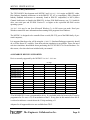
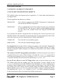
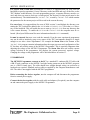
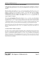
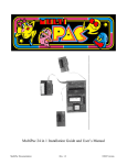
MCPM-3
USER'S MANUAL
A PROGRAMMER
FOR MOTOROLA
MC68HCx05
MICROCONTROLLERS
MC68HC805C4
MC68HC705C4A
MC68HC705C8
MC68HC705C8A
MC68HC705C9
MC68HC705C9A
MC68HC705D9
MC68HC705B5
MC68HC805B6
MC68HC705B16
MC68HC705P6
MC68HC705P6A
MC68HC705P9
MC68HC705J1
MC68HC705J2
The Engineers Collaborative, Inc.
Web: www.tec-i.com
E-Mail: [email protected]
MCPM-3 USER'S MANUAL
* * * IMPORTANT WARRANTY AND LIABILITY INFORMATION * * *
The Engineers Collaborative, Inc. warrants the diskette on which the software is furnished to
be free from defects in materials and workmanship for a period of 90 days from the date of
shipment to you. The MCPM-3 Programmer hardware is warranted for a period of 6 months.
This includes parts and labor and free technical support. Except as indicated above, there are
no other warranties, expressed or implied. No warranty of fitness for a particular purpose is
offered. The user is advised to test the software thoroughly before relying on it. The user assumes the entire risk of using the product. The total liability of The Engineers Collaborative,
Inc. is limited to the purchase price of the product, and does not cover any lost profits, special,
incidental or consequential damages, or any claim against the purchaser by any party.
* * * SOFTWARE LICENSE STATEMENT * * *
This software is protected by US copyright law and international treaty provisions. Therefore,
you must treat this software just like a book, with the following exception. The Engineers
Collaborative, Inc. authorizes you to make archival copies of the software for the sole purpose
of backing-up our software and protecting your investment from loss. By saying, just like a
book, The Engineers Collaborative, Inc. means that the software can not be used by two different people in two different places at the same time.
* * * OTHER * * *
The information contained in this manual has been carefully checked and is believed to be accurate and complete at the time of printing. However, no responsibility is assumed for errors
that might appear. The Engineers Collaborative, Inc. reserves the right to make changes to the
product and/or the manual at any time without notice. Furthermore, The Engineers Collaborative, Inc. assumes no liability arising out of the use or application of any of its products. No part
of this document may be copied or reproduced in any form or by any means without prior written consent of The Engineers Collaborative, Inc.
Trademarks:
IBM, IBM PC, XT, AT, PS-2, PC-DOS are registered trademarks of the IBM Corp.
Microsoft and MS-DOS are registered trademarks of Microsoft Corporation.
Motorola is a registered trademark of Motorola, Inc.
C ASYNCH MANAGER is a registered trademark of Blaise Computing, Inc.
Vermont Views is a registered trademark of Vermont Creative Software.
(C) Copyright 1989-2004 The Engineers Collaborative, Inc.
Web: www.tec-i.com
All rights reserved
Printed in the U.S.A.
The Engineers Collaborative Inc.
Page 2
MCPM-3 USER'S MANUAL
TABLE OF CONTENTS
1.0 INTRODUCTION......................................................................................................................................... 4
2.0 PACKING LIST............................................................................................................................................. 5
3.0 SYSTEM REQUIREMENTS ....................................................................................................................... 6
4.0 MC68HC05 DEVICES SUPPORTED.......................................................................................................... 6
5.0 GETTING STARTED................................................................................................................................... 7
5.1 CREATING A WORKING ENVIRONMENT............................................................................................. 7
5.2 THE DISTRIBUTION DISKETTE ........................................................................................................... 7
5.3 HARDWARE............................................................................................................................................. 8
5.4 INITIAL TEST OF THE MCPM-3 PROGRAMMER ................................................................................ 9
5.5 USING THE TUTORIAL EXAMPLE....................................................................................................... 9
6.0 TMCPM3.EXE PC BASED CONTROL PROGRAM................................................................................ 10
6.1 INVOKING TMCPM3 ............................................................................................................................. 10
6.2 TMCPM3 SCREEN DISPLAY ................................................................................................................ 10
6.3 TMCPM3 MENU OPTIONS ................................................................................................................... 11
7.0 THE MCPM-3 PROGRAMMER............................................................................................................... 20
7.1 POWER REQUIREMENTS ..................................................................................................................... 20
7.2 RS-232 PORT CONNECTIONS ............................................................................................................... 20
7.3 RESET PUSHBUTTON SWITCH .......................................................................................................... 20
7.4 GO/STOP PUSHBUTTON SWITCH ...................................................................................................... 20
7.5 PROGRAMMING INDICATOR LAMP .................................................................................................. 20
7.6 VERIFIED INDICATOR LAMP ............................................................................................................. 21
7.7 READY INDICATOR LAMP .................................................................................................................. 21
7.8 PC CONNECTED OPERATION............................................................................................................. 21
7.9 STAND-ALONE OPERATION ................................................................................................................ 22
7.10 CONCLUDING REMARKS .................................................................................................................. 23
8.0 TUTORIAL EXAMPLE SESSION............................................................................................................ 24
APPENDIX A - HC05DEMO.PRN LISTING................................................................................................... 26
APPENDIX B - HC05DEMO.MIK LISTING .................................................................................................. 28
APPENDIX C - MCPM-3 SCHEMATIC DIAGRAM...................................................................................... 28
The Engineers Collaborative Inc.
Page 3
MCPM-3 USER'S MANUAL
1.0 INTRODUCTION
The TECI microcomputer programmer Model MCPM-3 programs the on chip memory of the
Motorola 68HC05 series microcontrollers.
MCPM-3 is designed to work both in a development environment where it is attached to a personal computer and in a stand alone production environment where it is used to program 68HC05
microcomputers without being attached to a personal computer.
A wall mounted, UL listed plug-in power transformer supplies all necessary power to the programmer. During programming, power supply sequencing is automatically controlled by a microcomputer so that programming MC68HC05's in a production environment is a simple process
controlled by a single push-button switch that is provided on the front panel of the programmer.
The programmer has a high quality 40 pin ZIF (zero insertion force) programming socket on top
of the case. Optional 44 pin PLCC, 52 pin PLCC, and 28 pin and 20 pin DIP adapters are available from TECI. Three LEDs on the front of the programmer allow the operator to determine the
status of the programmer at a glance.
The RAM chip on the MCPM-3 Programmer is inserted into a Dallas Semiconductor Smart
Socket. The battery in this device has an estimated life span of 10 years under normal conditions.
This means that the Programmer can be moved from site to site without AC power or supplemental battery backup and retain all the information to successfully program the designated chips.
Additionally, in the event of AC power failure the Smart Socket isolates the RAM chip and prevents random noise and incomplete instructions from being written to it.
In the event the contents of the RAM chip are lost, built-in error checking informs the user that
the RAM must be reinitialized.
The TMCPM3.EXE software is menu driven with explicit operator prompts and error messages.
This driver program takes as its input 68HC05 object code files in either Motorola S-record
format or Intel Hex format, processes these files and downloads them to the MCPM-3 programmer. TMCPM3.EXE also allows the operator to perform many other useful functions such as
performing self tests of the MCPM-3 programmer, displaying and exporting the object code files,
filling unused EPROM locations with a user specified byte, changing communication ports and
more. TMCPM3.EXE was written in the C programming language.
The MCPM-3 Programmer Plus from TECI includes a complete set of integrated development
tools necessary to Assemble, Simulate, Debug and Program 68HC05 chips. The TASM05
Assembler and the SIMHC05 Simulator/Debugger are high quality tools designed to work seamlessly with the MCPM-3/TMCPM3.EXE programmer and driver. Those who purchase the
MCPM-3 Programmer package without the Assembler or Simulator/Debugger may use industry
standard tools that work with the Motorola S-Record or Intel file formats. The TASM05
Assembler and the SIMHC05 Simulator/Debugger are available separately from TECI.
The Engineers Collaborative Inc.
Page 4
MCPM-3 USER'S MANUAL
2.0 PACKING LIST
You should find these items in the shipping carton:
1.
2.
3.
4.
MCPM-3 Programmer Module
Wall Mounted Power Transformer
Manual
Software Diskette (found in the pocket of the manual)
Files on the Diskette:
TMCPM3.EXE
TMCPM3.HLP
HC05DEMO.ASM
HC05DEMO.MIK
HC05DEMO.PRN
5. Warranty Registration (found in the pocket of the manual)
If any of these items are missing, please call TECI to obtain them.
The Engineers Collaborative Inc.
Page 5
MCPM-3 USER'S MANUAL
3.0 SYSTEM REQUIREMENTS
The TECI 68HC05 development tools MCPM-3 and TMCPM3.EXE require an IBM PC, either
ISA (Industry Standard Architecture as in the IBM PC XT, AT or compatibles), EISA (Extended
Industry Standard Architecture as commonly found in IBM PC compatibles) or MCA (Micro
Channel Architecture as found in the IBM PS2). At least 256k RAM memory, one 5 1/4 inch disk
drive, one serial port and PC-DOS Version 2.1 or higher or the equivalent MS-DOS version
operating system.
TMCPM3.EXE may be run from Microsoft Windows 3.x in full screen text mode. Read your
Windows manual for more information about running DOS programs from Windows.
The MCPM-3 is designed to be controlled from a serial (RS-232) port of the IBM family of personal computers,
It is suggested that those who will be using the SIMHC05 Simulator/Debugger extensively should
do so on the fastest PC available. Even then real-time simulation is not possible. Those who need
real-time simulation, should think about purchasing the TECICE-HC05 In-Circuit Emulator. For
this reason, a fact sheet has been included with your manual.
4.0 MC68HC05 DEVICES SUPPORTED
Devices currently supported by the MCPM-3/TMCPM3.EXE are:
Device
MC68HC805C4
MC68HC705C4A
MC68HC705C8
MC68HC705C8A
MC68HC705C9
MC68HC705D9
MC68HC705B5
MC68HC805B6
MC68HC705B16
MC68HC705P6
MC68HC705P9
MC68HC05J1*
MC68HC705J2
40 Pin DIP
44 Pin PLCC
Package
52 Pin PLCC
28 Pin DIP
20 Pin DIP
YES
YES
YES
YES
YES
YES
N/A
N/A
N/A
N/A
N/A
N/A
N/A
YES w/adapter
YES w/adapter
YES w/adapter
YES w/adapter
YES w/adapter
YES w/adapter
N/A
N/A
N/A
N/A
N/A
N/A
N/A
N/A
N/A
N/A
N/A
N/A
N/A
YES w/adapter
YES w/adapter
YES w/adapter
N/A
N/A
N/A
N/A
N/A
N/A
N/A
N/A
N/A
N/A
N/A
N/A
N/A
YES w/adapter
YES w/adapter
N/A
N/A
N/A
N/A
N/A
N/A
N/A
N/A
N/A
N/A
N/A
N/A
N/A
YES w/adapter
YES w/adapter
*The MC68HC05J1 is not a programmable device. It is included in this list because the J2 may be
programmed as if it were a J1; as an emulation of the J1. Every place in this manual where the J1
is referred to indicates a remark about the J2 chip emulating a J1.
Adapters for all supported devices are available from TECI.
The Engineers Collaborative Inc.
Page 6
MCPM-3 USER'S MANUAL
5.0 GETTING STARTED
5.1 CREATING A WORKING ENVIRONMENT
5.2 SOFTWARE: THE DISTRIBUTION DISKETTE
TECI 68HC05 software development tools are supplied on a 5 1/4 inch double sided double density floppy diskette.
The files supplied on this diskette are as follows:
TMCPM3.EXE
This is the driver program for the MCPM-3 Programmer. It communicates
with and tests the MCPM-3 Programmer.
TMCPM3.HLP
This is a standard DOS text file that contains the help screen information
for TMCPM3.EXE. This file can be edited to include additional notes the
user may want to have available on-line when using the TMCPM3.EXE
program.
If you purchased the MCPM-3 Programmer Plus, the following files will also be present on your
distribution diskette. This manual does not discuss these files. For more information on these files,
refer to the sections in your User's Manual labeled TASM05 and SIMHC05.
TASM05.EXE
This is the 6805 cross assembler program.
SIMHC05.EXE
This is the 6805 simulator/debugger program.
It is assumed that the developer will be working on a computer with a hard disk. Though all the
tools included in this package may be run on a 8088 PC XT class computer with one 5.25" floppy
disk drive, inexpensive modern computers are available that will provide a more flexible working
environment.
The structure of the TECI programming environment is such that each project must reside in
a separate directory. For users of DOS versions 2.x the help file, TMCPM3.HLP must reside in
each of the project directories for it to be accessible to TMCPM3.EXE. For users of DOS versions
3.x and above the help file must reside in the same directory as TMCPM3.EXE.
For the XT user with one or two 5.25" floppy drives, make at least one backup copy of the
TECI diskette and at least one working copy of the same diskette. To make a backup, use the
DISKCOPY command. See your DOS manual for more information. To create a working copy of
the diskette, format a diskette with the /s switch to make a bootable floppy. Copy all the files from
your backup of the TECI diskette onto the bootable floppy disk and the working copy of the
diskette should be ready to use. For every project there must be a separate working copy diskette.
The initialization file, TMCPM3.INI, created by TMCPM3.EXE which contains the parameters
for the current project will be saved on the disk with the current project.
The Engineers Collaborative Inc.
Page 7
MCPM-3 USER'S MANUAL
For anyone with a hard disk (including the XT user) it is suggested that you work from the
hard disk to speed up operations. Create a directory on the hard disk and copy all the files on the
TECI diskette to that directory. For each programming project, a separate directory must be created, and when you want to work on a certain project, the directory for that project must be the
current directory. The initialization file, TMCPM3.INI, created by TMCPM3.EXE which contains
the parameters for the current project will be saved in the current directory.
For ease of use, it is suggested that (for users of DOS version 3.x and higher) the directory containing the TECI software be added to the PATH in the AUTOEXEC.BAT file in the ROOT directory on the hard disk. This will enable the user to start up TMCPM3.EXE from any directory that
is the current directory. To enable the PATH to the TMCPM3.EXE the computer must be rebooted. (Read your DOS manual for more information about the PATH command.)
It must be stressed that new users read the manuals. Even the most experienced programmer
may not be able to intuitively grasp every aspect of the TECI environment, though it is simple
enough to use after a short acquaintance. For example the Status Line at the bottom of the
TMCPM3.EXE program contains information about the target processor and configuration of the
PC but does not read the status of the MCPM-3 Programmer. This is especially important when
adjusting the voltage of the MCPM-3 Programmer. The Status Line does not read the current
voltage selection in the programmer, but displays the current processor's required voltage.
Changing the voltage on the programmer will be described below in section 6.3.
5.3 HARDWARE
The MCPM-3 Programmer connects to the PC by a standard 25 conductor RS-232 cable with
a DB-25 male connector on the MCPM-3 end (the mating connector on the MCPM-3 programmer is a DB-25 female type). The cable should have straight through wiring, no crossovers or
loopbacks are required. Standard modem cables as supplied by the computer manufacturer work
fine. The cable is not supplied with the MCPM-3 programmer.
Before connecting the devices together, turn the computer off and disconnect the programmer
from its external power supply.
Connect the devices together with the serial cable and adapters (if required), turn the computer
on and connect the power supply to the MCPM-3 Programmer.
The Engineers Collaborative Inc.
Page 8
MCPM-3 USER'S MANUAL
5.4 INITIAL TEST OF THE MCPM-3 PROGRAMMER
Certify that all the connections are secure, and make sure the MCPM-3 Programmer is turned on.
The Ready status light should be lit. If it isn't, press the Reset button on the right rear of the programmer.
Make the directory that contains TMCPM3.EXE the current directory. Start the TMCPM3.EXE
program and check the Status Line to make sure the Communications port is the one the programmer is hooked up to the default is Comm 1. If it isn't, then select the Change
Communications Port option using the down arrow and press <Enter> This will toggle the
communications port between Comm 1 and Comm 2. The TMCPM3.EXE program does not
support Comm 3 or Comm 4.
Then, select the Programmer Test option and press <Enter>. TMCPM3.EXE will communicate to the MCPM-3 Programmer and send a response to certify that communications have been
established. Press <Enter> again, according to the directions on the screen, to test the MCPM3 Programmer's RAM. This test is destructive to the contents of RAM and should not be done
while an object code file you wish to remain in the programmer is in the programmer's RAM.
If the tests fail, please check the cables and make sure the MCPM-3 Programmer is on. Make sure
that the Communications port in the TMCPM3.EXE program is the port the serial cable is attached to.
5.5 USING THE TUTORIAL EXAMPLE
Now that you have tested the MCPM-3 Programmer and it is functioning correctly, please invest
the time to read and follow through the tutorial example session that starts in Section 8.0 of this
manual. A demonstration 68HC05 program (HC05DEMO.ASM) is included on the distribution
diskette for this purpose. Going through the tutorial session will take just a short time and will
provide you with an overview of the MCPM-3 by actually using it, and it will make the rest of this
manual much more meaningful.
The Engineers Collaborative Inc.
Page 9
MCPM-3 USER'S MANUAL
6.0 TMCPM3.EXE PC BASED CONTROL PROGRAM
All interactions with the MCPM-3 programmer by the host computer are accomplished by selecting the
various options provided by the TMCPM3.EXE program.
This program operates on 6805 object code files in the standard Motorola S-record or Intel HEX formats.
6.1 INVOKING TMCPM3.EXE
TMCPM3.EXE is invoked by typing at the DOS prompt: TMCPM3.EXE <return>
Assuming the use of a hard disk and the use of the PATH command in the AUTOEXEC.BAT you may
invoke TMCPM3.EXE from any directory.
If there are multiple projects or multiple versions of the same project that require different settings,
then you must create a different directory for each project or version. If your project or version requires
the use of a different microcontroller, you must start TMCPM3.EXE from within the directory of that
project or version. When TMCPM3.EXE is exited, a file called TMCPM3.INI is created to save the
current settings. Whenever you invoke the program from that directory again, that local TMCPM3.INI
file determines the settings the program starts with. Any time TMCPM3.EXE is invoked from a directory that does not contain a TMCPM3.INI file, the default settings for TMCPM3.EXE (shown below
in Section 6.2) will be in place.
Assuming the use of TMCPM3.EXE from a bootable working floppy disk with one project per disk,
you may invoke TMCPM3.EXE from the A:\ or B:\ prompt.
6.2 TMCPM3.EXE SCREEN DISPLAY
When TMCPM3.EXE is invoked, the program menu screen is displayed. It looks something like this:
MCPM-3 MAIN MENU V4.0
Change 68HC05 Device Type
Adjust Vpp Voltage
Change Buffer Fill Character
Load Object Code File to Buffer
Download Buffer to Programmer Memory
Program 68HC05 Device
Upload Programmer Memory into Buffer
Examine/Edit Buffer Contents
Save Buffer in a File
Change Communications Port
Programmer Test
Help
Exit to DOS
Comm Port = 1
Fill Char = 00H
Vpp Should = 15.0 V
Device = MC68HC705C8
This is the default setting for the TMCPM3.EXE Transfer program. Before describing each of the
menu options some words on the general operation of the program are in order.
The Engineers Collaborative Inc.
Page 10
MCPM-3 USER'S MANUAL
TMCPM3.EXE creates a memory image of the object code file in the memory of the host computer
called the buffer. In other words, the object code file is decoded in the host computer to create an exact
memory image of the target microcontroller's memory. It is this buffer memory that is downloaded to
the programmer. This buffer can be initialized with a fill character and it can be displayed and edited
before sending it to the programmer. To verify proper communications between the host computer and
the programmer, all bytes of data sent to the programmer are placed in the programmer's RAM, read
back out of programmer RAM by the microcontroller in the programmer then echoed back to the host
computer which compares the data received with the data sent. If differences are found, error messages
are generated so that another attempt at downloading the buffer can be made. The actual programming
step at the programmer is not permitted until an error free download is achieved. With this general
understanding, each of TMCPM3.EXE's options will now be described
6.3 TMCPM3.EXE MENU OPTIONS
Change Device Type
Selecting the Change Device Type option brings up the device type selection menu that looks like this:
Device Type
68HC805C4
68HC705C8
68HC705C9
68HC705D9
68HC705B5
68HC805B6
68HC705P9
68HC705J1
68HC705J2
With the up and down arrow keys, select the processor desired and hit <Enter>.
* * * WARNING * * *
Changing the device type or even selecting the same device type as the current selection purges the
contents of the buffer. The buffer is filled with the erased state of the selected device (0 or FF).
You will be confronted with a dialogue box that reminds you to change the jumpers in the front of the
MCPM-3 Programmer. This dialogue box looks like this for the 68HC705C8 microcontroller. This is
the default microcontroller.
IMPORTANT MESSAGE
Set Programmer Internal Jumper Positions to:
J1=Most J2=Most J3=Most
Press any key to continue. . .
The jumpers must be switched if the chip requires a different setting from the one above. They are
located directly behind the front panel of the MCPM-3 Programmer. They are all labeled clearly and
may be changed without removing the top of the case. Below are the alternate settings for each of the
jumpers, and you will see these various settings for various chips.
The Engineers Collaborative Inc.
Page 11
MCPM-3 USER'S MANUAL
IMPORTANT MESSAGE
Set Programmer Internal Jumper Positions to:
J1=C9 J2=C9 J3=B5
Press any key to continue. . .
When you exit from that screen, the Main Menu selection is on Adjust Vpp Voltage. Do not press it
until you have read this section and the section following on Adjusting the Vpp Voltage.
On the bottom of the MCPM-3 Programmer you will find a label that details the current jumper and
voltage settings. The default settings for all the jumpers is the MOST position. For most of the supported microcontrollers this is correct setting. however the C9, D9 and B5 chips require different settings as shown in the chart below. If you are programming any of these chips, the jumpers must be
changed. To do this, follow the instructions below. Use the label on the bottom of the programmer to
keep track of the current settings.
* * * WARNING * * *
Always disconnect the MCPM-3 Programmer from its power transformer and disconnect the serial
cable from the rear of the device before opening the case.
First: Remove the two screws from the front panel of the MCPM-3 Programmer.
Second: Place the jumpers in the correct positions as described by the Important Message box displayed after choosing a microcontroller. Write the current setting to the label on the bottom of the
MCPM-3. Follow instructions for adjusting the Vpp voltage in the next section. The following table
exhaustively lists these settings for the current edition of the MCPM-3 Programmer:
Microcontroller
J1
J2
J3
MC68HC805C4
MC68HC805C4A
MC68HC705C8
MC68HC705C8A
MC68HC705C9
MC68HC705D9
MC68HC705B5
MC68HC805B6
MC68HC705B16
MC68HC705P6
MC68HC705P9
MC68HC705J1
MC68HC705J2
Most
Most
Most
Most
C9
C9
Most
Most
C9
Most
Most
Most
Most
Most
Most
Most
Most
C9
C9
Most
Most
REMOVED
Most
Most
Most
Most
Most
Most
Most
Most
Most
Most
B5
Most
B5
Most
Most
Most
Most
Require
d Vpp
19.5
19.5
15
15
13
13
15.5
19.5
15.5
16
16
16
16
* * * WARNING * * *
These voltage settings are for common mask versions of these chips. Different mask versions may require different voltage settings. If there is any question about the voltage settings for the specific microcontroller you are programming, please refer to your product literature for the correct settings. The
jumper settings listed above are correct.
Third: Replace the two screws of the front panel of the MCPM-3 Programmer, and plug in the serial
cable and power transformer.
The Engineers Collaborative Inc.
Page 12
MCPM-3 USER'S MANUAL
Adjust Vpp Voltage
The factory setting for the Programmer is Vpp=15.0. This is the setting for the popular
MC68HC705C8 Microcontroller. For any other chip the voltage will have to be adjusted.
Before you press <Enter> at the Adjust Vpp Voltage menu option, remove any microchip that
might be in the 40 pin ZIF socket or optional adapter. Vpp voltage is turned on to pin 3 of the programming socket soon after this option is pressed. Though the voltage may not harm the chip, it is
advisable to remove it.
The following text screen is invoked by pressing <Enter> at the Adjust Vpp Voltage option in the
main menu:
Remove device from programming socket . . .
Make sure that the desired device is selected and shown on the
status line.
If jumper J3 inside the programmer is in the B5 position, place
a jumper wire between pins 40 and 21 of the programming socket
to turn on the Vpp voltage.
If the jumper J3 is NOT in the B5 position, the Vpp voltage will
be turned on automatically.
Place a voltmeter between Pin 20(GND) and Pin 3(Vpp) of the programming socket.
Use a small screwdriver to adjust the Vpp voltage to the value
shown on the status line via the opening in the rear end panel
of the programmer.
Press any key when done . . .
Two reminders:
• The pins may all be accessed through the ZIF socket on top of the programmer. The top
of the programmer does not need to be removed to perform a voltage adjustment.
• The screw adjustment for the voltage is on the rear panel between the reset switch and
the RS-232 serial port.
Change Buffer Fill Character
When you change the 68HC05 device type the buffer fill character automatically changes to the erased
state of the selected device. You may, however, wish to change the buffer fill character to some other
value. Pressing <Enter> at this Main Menu selection will enable you to specify a HEX value between 00 & FF. Changing the buffer fill character will completely overwrite the buffer.
The Engineers Collaborative Inc.
Page 13
MCPM-3 USER'S MANUAL
Load Object Code File to Buffer
This command is used to get an object code file and load it into the host PC's RAM buffer.
When this option is selected, the operator is prompted to enter the file name of the object code file. The
complete file name must be entered including the file extension. File formats are automatically detected
by TMCPM3.EXE, and may be either Motorola S-Record, Intel Hex or a Binary memory image. If the
file name is entered correctly and can be opened and read by the computer a memory image in the format of the target chip is created in the buffer. If the file can not be opened, an error message is
displayed and the operator is given another chance to enter the file name. This continues until the
operator enters a correct file name or presses the Escape key. The operator is then given the option of
exiting the screen.
You may then Download Buffer to Programmer Memory or Examine/Edit Buffer Contents. For
a complete description of these options see below.
* * * WARNING * * *
The order in which you use the commands from the main menu is very important. If you wish to
change the device type, you must make sure that you have saved a copy of the buffer if you want to
keep it before you change the device type. When you change the device type (or even select the same
device type from the Change 68HC05 Device Type menu) the buffer is cleared and the default fill
character is written to the buffer. Next if you wish to put a different fill character in the buffer you must
do so before you Load Object Code File to Buffer. If you load the object code file first, then change
the fill character, the fill character will completely overwrite the contents of the buffer erasing any object code file currently in it. After selecting the device type and changing the fill character, the object
code file may be loaded.
Download Buffer to Programmer Memory
When this option is selected, the memory image in the buffer is downloaded into the MCPM-3's RAM,
where it is stored, until erased.
The Engineers Collaborative Inc.
Page 14
MCPM-3 USER'S MANUAL
Program 68HC05 Device
This menu option is context sensitive. Only the options available for the currently selected device are
offered. If the currently selected chip is an EEPROM memory then there will be an option for
Electrically Erasing the EEPROM memory. The following tables exhaustively list the programming
options for the available devices.
MC68HC805C4
MC68HC705C8
MC68HC705C9
Program and Verify Device
Verify Device Contents Only
Blank Check Device
Erase EEPROM Contents and Verify
Upload EEPROM Contents into Buffer
Production Programming Cycle
Program and Verify Device
Verify Device Contents Only
Blank Check Device
Secure EPROM Contents and Verify
Upload EPROM Contents into Buffer
Production Programming Cycle
Program and Verify Device
Verify Device Contents Only
Blank Check Device
Upload EPROM Contents into Buffer
Production Programming Cycle
Exit to Main Menu
Exit to Main Menu
Exit to Main Menu
MC68HC705D9
Program and Verify Device
Verify Device Contents Only
Blank Check Device
MC68HC705B5
Program and Verify Device
Blank Check Device
Exit to Main Menu
Upload EPROM Contents into Buffer
Production Programming Cycle
Exit to Main Menu
MC68HC805B6
Program and Verify Device
Verify Device Contents Only
Blank Check Device
Erase EEPROM Contents and Verify
Upload EEPROM Contents into Buffer
Production Programming Cycle
Exit to Main Menu
MC68HC705P9
Program and Verify Device
Verify Device Contents Only
Blank Check Device
Production Programming Cycle
Exit to Main Menu
MC68HC705J1
Program and Verify Device
Verify Device Contents Only
Blank Check Device
Production Programming Cycle
Exit to Main Menu
MC68HC705J2
Program and Verify Device
Verify Device Contents Only
Blank Check Device
Production Programming Cycle
Exit to Main Menu
For each command option there is a text screen displayed on the host computer. The user must follow
these instructions to complete the command.
* * * WARNING * * *
Before programming Windowed Ultraviolet erasable EPROM microcontrollers, Cover The Window.
Sunlight and florescent light may prevent correct programming of the device.
Program and Verify Device
Each menu has a Program and Verify Device option. This option assumes that there is an object
code file stored in the programmer's RAM. It then takes that object code file and writes it to the
programmable memory in the chip that is placed in the ZIF socket or adapter. Then it verifies that
all the code written to the memory is accurate.
The Engineers Collaborative Inc.
Page 15
MCPM-3 USER'S MANUAL
Verify Device Contents Only
This command verifies that all the code written to the microcontroller memory matches with the
code in the Programmer's RAM.
Blank Check Device
Checks the microcontroller's EPROM or EEPROM memory to certify that every location is in the
erased state.
Erase EEPROM Contents and Verify
For the 805C4 and 805B6 chips the EEPROM is electrically erasable. This means that using the
MCPM-3 Programmer, the operator may return the chip to its erased state. After this erase cycle,
the contents of EEPROM are checked against default value for these chips: $FF.
Secure EPROM Contents and Verify
This selection exists only for the 705C8. Unlike other chips in the HC05 family the security bit
must be set separately from the programming of the chip.
This command will not turn any of the status lights of the MCPM-3 Programmer on and when
finished the READY status light will come on. To verify that the device secured correctly, you
must try to upload its contents to the host PC. If you are unable to upload the contents then
the chip is secured.
Upload EPROM & EEPROM Contents into Buffer
This command reads the contents of the microcontroller's EPROM or EEPROM into the RAM
buffer in the host computer.
The Engineers Collaborative Inc.
Page 16
MCPM-3 USER'S MANUAL
Production Programming Cycle
The Production Programming Cycle will vary for different chips. Below is a list of steps and decisions that are made for each chip in the Production Programming Cycle.
Microcontroller
MC68HC805C4
MC68HC705C8
MC68HC705C9
MC68HC705D9
MC68HC705B5
MC68HC805B6
MC68HC705P9
MC68HC705J1
MC68HC705J2
Production Programming Cycle
1. Blank Check Device
A. If the EEPROM is not erased, then
2. Erase EEPROM Contents and Verify then
3. Program and Verify Device.
or
B. If the EEPROM is erased then
2. Program and Verify Device.
1. Blank Check Device
A. If Blank Check fails then end production programming cycle.
B. If chip is blank then
2. Program and Verify
3. Secure EPROM Contents
4. Verify Secure
1. Blank Check Device
A. If Blank Check fails then end production programming cycle.
B. If chip is blank then
2. Program and Verify
1. Blank Check Device
A. If Blank Check fails then end production programming cycle.
B. If chip is blank then
2. Program and Verify
N/A
1. Checks to see that security bit in object code file is on (cleared to 0)
A. If the security bit is not on, the programmer clears the bit and recalculates a new checksum
2. Blank Check Device
a. If the EEPROM is not erased, then
3. Erase EEPROM Contents and Verify then
4. Program and Verify Device.
or
b. If the EEPROM is erased then
3. Program and Verify Device.
or
B. If the security bit is on (0)
2. Blank Check Device
a. If the EEPROM is not erased, then
3. Erase EEPROM Contents and Verify then
4. Program and Verify Device.
or
b. If the EEPROM is erased then
3. Program and Verify Device.
1. Blank Check Device
a. If Blank Check fails then end production programming cycle.
b. If chip is blank then
2. Program and Verify
1. Blank Check Device
a. If Blank Check fails then end production programming cycle.
b. If chip is blank then
2. Program and Verify
1. Blank Check Device
a. If Blank Check fails then end production programming cycle.
b. If chip is blank then
2. Program and Verify
The Engineers Collaborative Inc.
Page 17
MCPM-3 USER'S MANUAL
Exit to Main Menu
This option returns the user to the TMCPM3.EXE Main Menu.
This is the end of the description of the Program 68HC05 Device sub menus.
Upload Programmer Memory to Buffer
Selecting this option causes the programmer to send the contents of its RAM to the buffer memory in
the host PC.
Examine/Edit Buffer Contents
Selecting this option allows the user to examine and/or edit the buffer contents.
If the user wishes, the buffer may be edited by typing over the current contents of memory locations.
The cursor may be moved around the screen using the arrow keys. Typing TAB toggles the cursor
between the HEX portion of the screen and the ASCII portion of the screen. Non-HEX keys are disabled in the Hex portion of the screen, non-printable characters are disabled in the ASCII portion of the
screen.
To move through the memory map in the buffer, use the Page Up and Page Down keys. Each page
displays 256 bytes of information. The buffer varies in size according to the currently selected device.
The smallest buffer is 1k for the J1 device and the largest is 16k for the C9 and D9 devices.
Save Buffer in a File
This option allows you to save the current contents of the buffer in one of three file formats, Motorola
S-Record, Intel HEX or Binary image format.
When you select this option, you are asked to name the new file. It is not necessary to type the full path
if you want to store the file in the current directory. If you wish to save the file in another directory or
disk, you must type the full path and file name. The ordinary extension for the Motorola S-Record is
*.MIK for Intel HEX it is *.HEX, binary code files are often saved as *.BIN. These are just conventions, meant to help organize your work, not strict rules. The TMCPM3.EXE program will read any
of the files you save with it in any format selected with any extension you choose.
Change Communications Port
This option toggles the active communications port between COM 1 and COM 2. COM 3 and COM 4
are not supported. The active port is reflected on the left side of the status line.
The Engineers Collaborative Inc.
Page 18
MCPM-3 USER'S MANUAL
Programmer Test
Simply, this menu option certifies that the MCPM-3 Programmer and PC are communicating. If they
are not communicating, the TMCPM3.EXE software will display an error message:
Communications Error - Serial Port Timeout
A character was expected from the programmer and was not received.
Verify that the programmer is connected to com1*
Note:
The communications port may be changed via the main menu.
Check power to the programmer . . .
Press the programmer 'Reset' pushbutton and
Verify that the 'Ready' lamp is on . . .
Press 'Q' to return to the main menu. . . or any other key to try again.
*(The setting on the status line of the main screen, com1 or com2)
If they are communicating, the message will read:
Communications with the programmer(RS-232) checks OK . . .
Verify that the Programmer Lamps are on.
Press <Return> to test programmer ram, or any other key to return to the
menu.
The Programmer RAM test writes a string of bytes to the RAM chip on in the Programmer and tests it.
Therefore, if there has been a program downloaded into the RAM from the host PC, it will be
overwritten and destroyed.
* * * WARNING * * *
The RAM test is destructive to the contents of the MCPM-3 Programmer RAM. Do not test RAM
before programming microcontrollers.
Help
This option opens the help screen. The help screen may be scrolled through using the page up and
page down keys or using the arrow keys. To exit the Help screen, press Escape.
Exit to DOS
This menu selection will end the TMCPM3.EXE session.
The Engineers Collaborative Inc.
Page 19
MCPM-3 USER'S MANUAL
7.0 THE MCPM-3 PROGRAMMER
The MCPM-3 programmer is a 5.5 inch wide X 6.5 inch deep X 1.5 inch high cabinet with a 40 pin
ZIF (Zero Insertion Force) socket extending through the top. Extending through the rear panel is one
RS-232 port, a reset switch and a 12 volt AC connector. Also there is a hole through which the voltage
may be adjusted. The front panel contains Programming, Verified and Ready LEDs and a Go/Stop
Switch.
Inside is a double sided printed circuit board with silk screened component legends. It has a
microcontroller that performs the serial input and output to and from the host computer, the power
supply sequencing during programming operations and all other control functions.
7.1 POWER REQUIREMENTS
The MCPM-3 comes with a standard UL approved 12 volt AC power supply. All the necessary power
requirements for programming the 68HC05 chips come from this power supply. For foreign users, any
commercially available adapter that provides 110 volts @ 50hz or 60hz with a US socket for the 12
volt power supply will satisfy the requirements of the programmer.
7.2 RS-232 PORT CONNECTIONS
See section 5.1.2.
7.3RESET PUSH-BUTTON SWITCH
The RESET push-button switch is located on the left side of the programmer's back panel. It is the reset control for the internal microcomputer. The user will not have to use this control often. It is included
so that the internal micro can be brought to a known state after unexpected things happen such as
power glitches. Applying power to the programmer also resets the microcomputer. This does not
change the RAM content in the programmer or delete the last command sent by the host computer.
7.4 GO/STOP PUSH-BUTTON SWITCH
The GO/STOP push-button switch does one thing. It repeats the last command sent to the MCPM-3
Programmer by the TMCPM3.EXE transfer program on the host computer. It will not, however, repeat
any command from the Main Menu. Only the commands from the sub menu of the Program 68HC05
Device Main Menu selection will be remembered.
7.5 PROGRAMMING STATUS LIGHT
The PROGRAMMING status light is an LED that is illuminated to indicate that the chip programming
sequence is in progress. It is also illuminated during the programmer self test as described below, and
when special programs are being sent to the B5 and B6 microcontrollers.
The Engineers Collaborative Inc.
Page 20
MCPM-3 USER'S MANUAL
7.6 VERIFIED STATUS LIGHT
The VERIFIED status light is an LED that is illuminated to indicate the successful completion of operations. When the programmer is being operated by the host PC, the VERIFIED status light only
remains lit for a brief period before the READY status light is turned on.
7.7 READY STATUS LIGHT
The READY status light is an LED that is illuminated to indicate that the programmer is ready to receive another command or that a device can be inserted or removed from the programming socket.
This light also toggles on and off during serial I/O operations with the host computer to give the operator some indication things are happening as they should. Since this light is ON most of the time, it is
also used to indicate that power is applied to the programmer.
* * * NOTE * * *
On power up, if the READY status light comes on and stays on the non-volatile memory is still good.
On power up, if all the status lights flash on and off, the programmer RAM has been corrupted. To
program or test any further device, the programmer must again be attached to the host computer for
downloading of the object file and command.
7.8 PC CONNECTED OPERATION
Whenever the programmer must interact with the host computer it must be connected with the RS-232
cable. The operator controls all programmer functions by selecting options from the TMCPM3.EXE
program menu. Generally in this situation the operator is performing development activities, uploading/downloading files to the programmer, setting up or testing the programmer or other related activities as described under the section on the TMCPM3.EXE program.
If the commands for the programmer were initiated by the host computer from the Program 68HC05
Device submenu, the programmer sends the result information to the host computer screen. If, however, the command came from the programmer itself, repeating the last command from the host computer when the operator pressed the GO/STOP pushbutton switch the results are shown by the LEDs
on the front panel.
The Engineers Collaborative Inc.
Page 21
MCPM-3 USER'S MANUAL
7.9 STAND-ALONE OPERATION
Stand alone operation is completely dependent on the last command sent to the MCPM-3 Programmer
by the host PC. As soon as the user disconnects the serial cable from the programmer, or decides to use
the programmer without TMCPM3.EXE, the programmer keeps the last command as the current
command.
To perform the last command of the host PC, push the GO/STOP button.
When the last command from the host computer was Program and Verify Device, the result will be
as follows:
When the READY status light is on, the operator inserts the device to be programmed into the programming socket on the top of the cabinet, pulls the lever forward, and presses the GO/STOP button.
This initiates the programming sequence and is indicated by the PROGRAMMING status light coming
on. When the chip is finished being programmed the PROGRAMMING light goes off. If the verification
process is successful, the VERIFIED status light comes on and the READY status light comes on to
indicate completion of the task. The status lights continue to show the result status until the programmed chip is removed from the socket and a new chip is placed in the socket and the GO/STOP
button is pressed to repeat the Program and Verify Device command.
To program any device:
* Status: Clamp lever on ZIF socket must be in vertical position.
1.) Insert chip to be programmed with pin 1 to the left rear.
2.) Pull clamp lever on ZIF socket forward to the horizontal position. (This step should also be
used with all adapters that fit the 40 pin socket.)
* Status: READY status light is on and the VERIFIED status light is on only if the programmer
has successfully programmed a chip in the stand alone mode once already without further commands from the host computer. If this is the first time the programmer has been used in the stand
alone mode the VERIFIED status light will not be on. or if the programmer was not successful
programming the previous chip, the VERIFIED status light will not be on.
3.) Push GO/STOP button on right front of MCPM-3 panel.
* Status: PROGRAMMING status light is on until the chip is programmed.
* Status: MCPM-3 Programmer attempts to verify the chip.
* Status: If the chip verifies the VERIFIED status light goes on. If it does not verify the chip, the
VERIFIED status light does not go on.
* Status: Then the READY status light goes on. The VERIFIED status light stays on if the programming attempt was successful when the programmer is in stand alone mode.
When the last command from the host computer was Verify Device Contents Only, the VERIFIED
status light comes on to verify successful completion.
When the last command from the host computer was Blank Check Device, the VERIFIED status
light comes on to indicate that the device is blank.
The Engineers Collaborative Inc.
Page 22
MCPM-3 USER'S MANUAL
When the last command from the host computer was Erase EEPROM Contents and Verify, the
VERIFIED status light comes on to indicate that the device erased successfully.
When the last command from the host computer was Upload EPROM Contents into Buffer or
Upload EEPROM Contents into Buffer , the READY status light blinks to indicate the transfer of
data to the host computer.
When the last command from the host computer was Production Programming Cycle, the list of
actions described above in the Production Programming Cycle for the specific device to be programmed will be performed in the sequence described. For each command in the cycle the status lights
will turn on and off according to the description in this section.
By now the reader probably has a pretty good idea of what stand-alone operation is. To repeat, standalone operation occurs when the programmer is not connected to the computer. It was conceived to be
used in a production environment where many MC68HC05 microcomputer chips are to be programmed without having to tie up computer resources.
7.10 CONCLUDING REMARKS
This description of the MCPM-3 Programmer, both in computer-connected and stand-alone operation
should give you a good idea of how it works. However there is no substitute for practice. The tutorial
example below is provided to give you a feel for the actual process. For both first time users and
experienced engineers, this tutorial is a necessary step in mastering the basics of MCPM-3 and
TMCPM3.EXE.
The Engineers Collaborative Inc.
Page 23
MCPM-3 USER'S MANUAL
8.0 TUTORIAL EXAMPLE SESSION
The distribution diskette contains a file named HC05DEMO.ASM. This is an MC68HC705C8 source
code file that we will use to become familiar with the MCPM-3 programmer and tools. We will download the memory image of the object code file (HC05DEMO.MIK) to the programmer to see how it is
used in actual practice.
HC05DEMO.ASM specifies a very simple program for the C8 to execute, it continuously outputs the
characters of the message "How now brown cow." to port A and strobes port B bit 0 each time that a
character is output. The characters are to be output one every millisecond until the end of the message
is reached at which time the message repeats in an endless loop. Study the program source code
HC05DEMO.ASM by looking at it with your text editor or by printing it. (For more information on the
DOS PRINT command see your DOS manual.)
The program uses the on chip timer to interrupt the processor every 1.000 milliseconds.
HC05DEMO.ASM assumes that we have a 4.0 Mhz crystal attached to the processor so that the timer
register increments once every 2 microseconds. To generate a timer interrupt once every millisecond,
the program makes use of the output compare feature of the timer. The number 500 is added to the
contents of the output compare register every time a timer interrupt occurs (500 x 2 microseconds = 1
millisecond) so that another timer interrupt will occur 1 millisecond later in time. Review the listing to
convince yourself that this is actually the case.
On your distribution diskette you will find the file named HC05DEMO.PRN (found in Appendix A)
and an object code file named HC05DEMO.MIK (found in Appendix B).
Tutorial:
1. Make the directory where you installed TMCPM3.EXE the current directory. Then, type
TMCPM3.EXE <Enter> at the DOS prompt to invoke the program. The program should look for
the help file TMCPM3.HLP then display the Main Menu.
2. Now, to program a 68HC705C8 device, use the arrow key to select the Change 68HC05 Device
Type menu item and then press <Enter>.
3. Use the arrow key to select the 68HC705C8 device and press <Enter>. You will be warned to
make sure the jumpers in the MCPM-3 Programmer are in the correct position. To find out, look at the
label on the bottom of the MCPM-3 Programmer and the current settings will be found. (Use this label
in the future to mark the current settings if you change them.) The default settings, J1 MOST, J2
MOST and J3 MOST are the settings that the 68HC705C8 requires.
If you wish, you may check the voltage at this time. Consult Section 6.3 Adjust Vpp Voltage. For the
Tutorial this will be unnecessary because the default chip for the MCPM-3 Programmer is the C8 chip.
The voltage will be correct.
The Engineers Collaborative Inc.
Page 24
MCPM-3 USER'S MANUAL
4. The next step is to change the fill character. After exiting the previous screen, select the Change
Buffer Fill Character in the Main Menu. Press <Enter>. Type in a valid Hex number between $00
and $FF and exit the screen. Choose the Examine/Edit Buffer Contents Main Menu, press
<Enter> and view the new buffer fill character. Press <Esc> to exit that screen.
5. Choose the Load Object Code File to Buffer Main Menu option. Press <Enter>. Type
HC05DEMO.MIK and press <Enter>. Exit that screen and the object code file is placed in the
buffer. Choose the Examine/Edit Buffer Contents Main Menu, press <Enter> then press the page
down key and view the object code file that contains the string "How now brown cow". (To edit the
file, see Section 6.3 Examine/Edit Buffer Contents.) Exit the screen by pressing <Esc>.
6. Now you are ready to send the object code file to the MCPM-3 Programmer. Select the
Download Buffer to Programmer Memory. Press <Enter>.
The screen will clear, and a message stating that the buffer memory image is being downloaded to the
programmer is displayed. The Ready indicator light on the front of the MCPM-3 Programmer should
be flashing to indicate communication activity with the host computer.
The next step to programming a device would be to select the Program 68HC05 Device. This tutorial
will not go through this step. Please go to the step 7 in the tutorial, or if you want to program a chip
with the current contents of the programmer RAM, read Section 6.3 Program 68HC05 Device and
follow the instructions. However, we suggest you use an erasable C8 device.
7. This step in this tutorial allows you to view the contents of the programmer RAM. Press any key
to continue and choose the Upload Programmer Memory to Buffer Main Menu option. Press
<Enter>. The Ready indicator light will flash very quickly, appearing to dim, while the Programmer
uploads the file. You will be returned to the Main Menu automatically upon completion.
That's it! You have just performed all of the necessary steps in the development process using the
TECI tools, except programming and verifying a chip.
We sincerely hope that after using these tools you will consider them to be a sound investment. We
look forward to your comments and suggestions and to providing any assistance with their use that you
may require.
The Engineers Collaborative Inc.
Page 25
MCPM-3 USER'S MANUAL
The Engineers Collaborative, Inc. 6805/6305 Cross Assembler Version 2.3
APPENDIX A - HC05DEMO.PRN LISTING
DEMO Program for familiarization with TECI tools
;******************************************************************************
;**
An MC68HC705C8 Demonstration Program
**
;** This program outputs the characters of the message "How now brown cow."
**
;** one character every 1.000 milliseconds to port A and strobes bit 0 of
**
;** port B. When the end of the message is reached, the message repeats in
**
;** an endless loop. The on chip timer is used to provide the required time
**
;** intervals.
**
;**
fname = HC05DEMO.ASM
**
;**
5/05/89 RBJ
**
;**
The Engineers Collaborative, Inc.
**
;** Route 3, Box 8C Barton, Vermont 05822
Phone (802) 525-3458
**
;******************************************************************************
;
0050 ram
equ
$50
;start of ram area
0100 rom
equ
$100
;start of rom area
2000 vectors
equ
$2000
;interrupt vectors
0000 port_a
equ
0
;port a data register
0001 port_b
equ
1
;port b data register
0002 port_c
equ
2
;port c data register
0003 port_d
equ
3
;port d data register
0004 port_a_ddr
equ
4
;port a data direction reg.
0005 port_b_ddr
equ
5
;port b data direction reg.
0006 port_c_ddr
equ
6
;port c data direction reg.
000A spi_control
equ
10
;spi control reg
000B spi_status
equ
11
;spi status reg.
000C spi_data
equ
12
;spi data reg.
000D sci_baud
equ
13
;sci baud rate reg.
000E sci_control_1
equ
14
;sci control reg. 1
000F sci_control_2
equ
15
;sci control reg. 2
0010 sci_status
equ
16
;sci status reg.
0011 sci_data
equ
17
;sci data reg.
0012 timer_control
equ
18
;timer control reg.
0013 timer_status
equ
19
;timer status reg.
0014 input_cap_high
equ
20
;input capture high reg.
0015 input_cap_low
equ
21
;input capture low reg.
0016 output_cmp_high
equ
22
;output compare high reg.
0017 output_cmp_low
equ
23
;output compare low reg.
0018 tcounter_high
equ
24
;timer counter high reg.
0019 tcounter_low
equ
25
;timer counter low reg.
001A acounter_high
equ
26
;alternate counter high reg.
001B acounter_low
equ
27
;alternate counter low reg.
;
0050
org
ram
;ram variables
0050 pointer
rmb
1
;
;
0100
org
rom
;start of program memory
0100 486F7720 message
db
'How now brown cow.' ;Define the message text
6E6F7720
62726F77
6E20636F
772E
;
0112 A6FF power_on_reset
lda
#%11111111
;program start on reset
0114 B704
sta
port_a_ddr
;port a set to outputs
0116 B705
sta
port_b_ddr
;port b set to outputs
0118 B750
sta
pointer
;initialize pointer variable
011A A601
lda
#500/256
;initialize output compare reg
011C B716
sta
output_cmp_high
;
011E B613
lda
timer_status
;
0120 A6F4
lda
#500 & $ff
;
0122 B717
sta
output_cmp_low
;
0124 1C12
bset
6,timer_control
;enable output compare int
0126 9A
cli
;enable interrupts
0127 20FE wait_loop
bra
wait_loop
;wait here for timer int's
The Engineers Collaborative Inc.
Page 26
MCPM-3 USER'S MANUAL
;******************************************************************************
;**
timer interrupt service routine
**
;**
The timer counter register increments once every 1.0 / (4.0Mhz / 2 / 4)
**
;**
= 2 microseconds with a 4.0 Mhz external clock frequency.
**
;**
To generate timer interrupts at 1 millisecond intervals the output
**
;**
compare feature of the timer can be used by adding 500 to the output
**
;**
compare register every time a timer interrupt occurs.
**
;**
**
;**
When this routine is called, 500 is added to the output compare register
**
;**
then bit 0 in the timer control register is toggled so that a two
**
;**
millisecond square wave appears on the TCMP pin.(1ms high,1ms low)
**
;**
Then the X register is loaded with the
**
;**
character pointer variable, X is then incremented and saved back to
**
;**
the pointer location for use on the next timer interrupt, X is then
**
;**
used to access the character in the message that is to be output. The
**
;**
character is output to port A and bit 0 of port B is strobed. If the
**
;**
last character of the message is reached, indicated by the period(.),
**
;**
the pointer is initialized so that it will access the first character
**
;**
of the message the next time that this routine is called.
**
;******************************************************************************
;
0129 0D132A timer_isr
brclr
6,timer_status,tisr_end ;branch if no out compare flag
012C B617
lda
output_cmp_low
;add 500 to output compare reg
012E ABF4
add
#500 & $ff
;one millisecond counter
0130 97
tax
;save for awhile
0131 B616
lda
output_cmp_high
;
0133 A901
adc
#500/256
;
0135 B716
sta
output_cmp_high
;write high byte first so
0137 BF17
stx
output_cmp_low
;compares won't be inhibited
0139 B612
lda
timer_control
;
013B A801
eor
#%00000001
;toggle the olvl bit so tcmp
013D B712
sta
timer_control
;pin will toggle
013F BE50
ldx
pointer
;get the char pointer
0141 5C
incx
;point to the next char
0142 BF50
stx
pointer
;save for next time
0144 D60100
lda
message,x
;get the character
0147 B700
sta
port_a
;output it to port a
0149 1001
bset
0,port_b
;strobe
014B 9D
nop
;port b
014C 1101
bclr
0,port_b
;bit 0
014E A12E
cmp
#46
;was the char a period?
0150 2604
bne
tisr_end
;branch if not
0152 AEFF
ldx
#$ff
;reinit character
0154 BF50
stx
pointer
;pointer if so
0156 80 tisr_end
rti
;
0157 80 external_isr
rti
;external irq
0158 80 software_isr
rti
;swi
0159 80 spi_isr
rti
;serial peripheral interface
015A 80 sci_isr
rti
;serial communication interface
;
1FF4
org
vectors - 12
;interrupt service routine vectors
1FF4 0159
dw
spi_isr
;serial peripheral interface
1FF6 015A
dw
sci_isr
;serial communication interface
1FF8 0129
dw
timer_isr
;timer
1FFA 0157
dw
external_isr
;external irq
1FFC 0158
dw
software_isr
;swi
1FFE 0112
dw
power_on_reset
;reset
Assembly complete - Errors = 0 , Warnings = 0
The Engineers Collaborative Inc.
Page 27
MCPM-3 USER'S MANUAL
APPENDIX B - HC05DEMO.MIK LISTING
Object code file created by TASM05 during assembly of the Appendix A example source file.
S1130100486F77206E6F772062726F776E20636F0F
S1130110772EA6FFB704B705B750A601B716B613D6
S1130120A6F4B7171C129A20FE0D132AB617ABF4C7
S113013097B616A901B716BF17B612A801B712BE13
S1130140505CBF50D60100B70010019D1101A12ED3
S10E01502604AEFFBF5080808080803A
S10F1FF40159015A01290157015801123A
S9030000FC
The Engineers Collaborative Inc.
Page 28