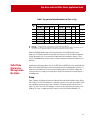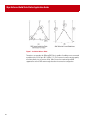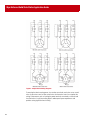
1
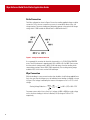
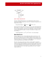
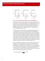
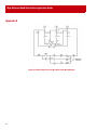
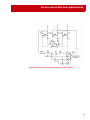
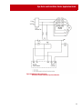
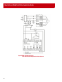
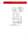
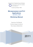
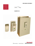
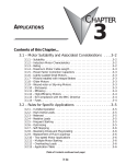
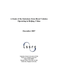
WHITE PAPER
WYE-DELTA AND SOLID
STATE STARTER APPLICATION
GUIDE
EXPLANATION AND ASSISTANCE FOR APPLYING
SOLID STATE SOFT STARTERS IN TRADITIONAL
REDUCED VOLTAGE APPLICATIONS
Introduction. . . . . . . . . . . . . . . . . . . . . . . . . . . . . . . . . . . . . . . . . . . . . . . . . . . . . . . . . . . . . .2
Power Distribution Terminology. . . . . . . . . . . . . . . . . . . . . . . . . . . . . . . . . . . . . . . . . . . .2
Traditional Design Theory . . . . . . . . . . . . . . . . . . . . . . . . . . . . . . . . . . . . . . . . . . . . . . . . .3
Delta Connection . . . . . . . . . . . . . . . . . . . . . . . . . . . . . . . . . . . . . . . . . . . . . . . . . . . . . . .4
Wye Connection. . . . . . . . . . . . . . . . . . . . . . . . . . . . . . . . . . . . . . . . . . . . . . . . . . . . . . . .4
Motor Identification . . . . . . . . . . . . . . . . . . . . . . . . . . . . . . . . . . . . . . . . . . . . . . . . . . . . .5
Electro-Mechanical Wye-Delta vs. Solid-State Starters. . . . . . . . . . . . . . . . . . . . . . .7
Solid-State Starting Advantages . . . . . . . . . . . . . . . . . . . . . . . . . . . . . . . . . . . . . . . . . . .9
Solid-State Starters for Wiring Inside-the-Delta. . . . . . . . . . . . . . . . . . . . . . . . . . . . .11
Sizing . . . . . . . . . . . . . . . . . . . . . . . . . . . . . . . . . . . . . . . . . . . . . . . . . . . . . . . . . . . . . . .11
Connections and Set-up. . . . . . . . . . . . . . . . . . . . . . . . . . . . . . . . . . . . . . . . . . . . . . . . .13
Application Examples. . . . . . . . . . . . . . . . . . . . . . . . . . . . . . . . . . . . . . . . . . . . . . . . . . . .15
Important Application Considerations. . . . . . . . . . . . . . . . . . . . . . . . . . . . . . . . . . . . . .17
Appendix A . . . . . . . . . . . . . . . . . . . . . . . . . . . . . . . . . . . . . . . . . . . . . . . . . . . . . . . . . . . . .18
Wye-Delta and Solid State Starter Application Guide
Introduction
The theory of applying reduced voltage to a motor for the purpose of altering the motors
torque and power consumption characteristics is an idea that has existed for many years.
These concepts have flourished mainly due to the need to limit torque and limited
generator/power distribution capabilities. In addition, energy conservation initiatives have
forced local governments to place mandatory reduced voltage starting requirements on
motors rated at 7.5 Hp (5.5 kW) and larger.
Reduced voltage starting can be accomplished through various methods including part
winding, wound rotor, auto-transformer, wye-delta, or solid-state. While many of these
techniques require specialty motors or special system components, the wye-delta and
solid-state method are the simplest to apply. Applications employed throughout the United
States differ, but over the years the dominant method world wide has been the wye-delta
or star-delta starting technique.
The latest generation of soft starters and Smart Motor Controllers (SMCs) offer significant
advantages over its predecessors when it comes to applying it in wye-delta applications. In
most cases these solid-state products can be used to replace or retrofit any of the
traditional reduced voltage methods. The SMC product line has been specially designed to
take full advantage of solid-state technology and advanced features to provide a cost
effective modular solution to both new and old reduced voltage applications.
Power
Distribution
Terminology
Approximately 75% of the world’s power systems are supplied as wye power from the
transformer. Whether the power is supplied as wye or delta makes little difference to the
system starter components provided there is an appropriate voltage potential and phase
relationship present. The diagram shown as Figure 1 illustrates a simple connection
scheme of the incoming utility power through the motor. Keep in mind that there are many
different configurations throughout the world, but a wye configured system operating at
380 to 415V is the most common. In the United States there is both wye and delta power
systems ranging from 240 to 480V AC.
When this document uses the term wye-delta motor configuration, it is simply referencing
the way in which the motor windings are connected to the power system. As we will
discuss, the physical connection of these windings has an effect on the actual applied
voltage to the windings regardless of the power configuration from the transformer.
2
Wye-Delta and Solid State Starter Application Guide
Figure 1. Simple System Line Diagram
Traditional
Design Theory
By definition, wye-delta is a traditional electro-mechanical method of reducing the voltage
applied to the motor during starting. While this method has significant advantages over
conventional full voltage starting, the disadvantage is that it requires more panel space, more
components, and most importantly a motor that has all its winding terminations available to the
outside so the wye connection can be created.
While the term “reduced voltage starter” is used for the wye-delta starting method, in actuality
the full line voltage is still being applied to the motor leads. The reduced voltage occurs simply
because of the electrical characteristic of the Wye vs. Delta relationship.
33
Wye-Delta and Solid State Starter Application Guide
Delta Connection
The Delta configuration shown in Figure 2 shows the resulting applied voltage on a delta
connection. This is the most common way a motor is connected for direct on line, full
voltage starting. The motor windings are designed to operate at the nominal full voltage
rating, which is 400V outside the United States or 480V within the U.S.
Figure 2. Voltage on Delta Connection
As an example let's examine the electrical characteristics of a 15 kW/20 Hp 1800 RPM
motor. The full load current is approximately 30 A at 400V or 26 A at 480V. If we assume
that the nominal starting current is 600% of full load current, then the resulting inrush
current during starting is about 180 A/156 A respectively. The resulting starting torque
would be 100% of the motors nominal full load torque.
Wye Connection
With the windings in a wye connection rather than the delta, the full voltage applied line to
line is the same, but the voltage across the individual motor windings is reduced as shown
in Figure 3. The voltage is reduced by the inverse of the square root of 3 or 57.7% of full
voltage.
1 ⎞
480V 480
x 480 = (.577) x 480 = 277V
Starting Voltage Reduction = ------------ = --------- = ⎛
3 1.73 ⎝ 1.73⎠
For power systems with a Line to Line (L to L) voltage of 400V or 480V the actual voltage
across the motor windings is the Line to Neutral (L to N) voltage of 230V or 277V
respectively.
4
Wye-Delta and Solid State Starter Application Guide
Figure 3. Voltage on Wye Connection
The effect of applying reduced voltage across the windings during starting can be best
explained by our example. Using the wye connection, the starting current is proportional to the
voltage reduction therefore:
LRA⎞
156 ⎞
Starting Current Reduction = ⎛
x 57.7% = ⎛
x 57.7% = 51 A
⎝ 1.73⎠
⎝ 1.73⎠
Using the information (LRA = 180 A/156 A) the wye connection current would be approximately
60 A for 400V or 51 A for 480V. It is easy to notice the large reduction in current, however the
result of the reduced voltage also means that some starting torque is sacrificed. The reduction
in torque would be approximately equal to the square of the reduction of voltage across the
motor windings, or:
2
2
Starting Torque Reduction ∞ (%V ) = (.577 ) x 100% = 33% of full load torque
Motor Identification
Whether the application is new or existing, identifying wye-delta connected motors can be
easy. The motor nameplate and connection diagram will typically indicate wye-delta or stardelta, but there may also be references to low volts and high volts. As discussed previously, the
voltage plays a big part in the characteristics of wye-delta applications. This is why the most
common voltage combinations are 220/380V AC and 277/480V AC.
Physically a single voltage wye-delta motor will have six leads marked T-1 through T-6. In
comparison a standard single voltage delta motor has three leads which are marked T-1 through
T-3. For dual voltage motors the wye-delta motor will have 12 leads marked T-1 through T-12
where as the standard delta motor has nine leads T-1 through T-9. Figure 4 shows two common
connection diagrams for both a six-lead single voltage wye-delta motor and a 12-lead dual
voltage wye-delta motor.
55
Wye-Delta and Solid State Starter Application Guide
Figure 4. Sample Motor Nameplate Diagrams
While investigating existing applications, look at the installed starter taking special note of
the number of contactors and overloads. The majority of traditional wye-delta starters will
have three contactors (two typically the same size and one slightly smaller) along with one
overload. Keep in mind that there are other possible six-lead motor configurations such as
two-speed motors which in contrast have two overloads. In these cases it is best to
compare the system components to the schematics shown in Appendix A and look for other
key indicators such as operating voltage, nameplate information, and available connection
diagrams.
Though these are the most common configurations, there is no limit to the amount of
variations or special motors that could exist. Therefore, in addition to the physical
information it is important to realize that 80% of standard IEC style 50 Hz motors have six
or twelve leads and are designed for wye-delta starting. Less then 1% of standard 60 Hz
NEMA style motors are wired wye-delta and most are special ordered unless larger than
the 200 Hp frame size where many manufactures make the connections standard.
The diagram shown in Figure 5 represents a common connection diagram taken from an
actual six-lead motor. In this case all of the wires would be available at the terminal or
conduit box. The first phase leads are numbered “T1” and “T4”. The second phase “T2” and
“T5”, and the last is numbered “T3” and “T6”.
6
Wye-Delta and Solid State Starter Application Guide
Figure 5. Sample Wye-Delta Connection Diagram
As noted in Figure 4 (A) for connecting the motor for full voltage, leads 1 and 6 are connected
together forming T1 and connected to L1. Correspondingly leads 3 and 5 as well as 2 and 4 are
connected together forming T3 and T2. When connecting the motor for reduced voltage and
starting current the leads must be connected in the wye or star configuration. By connecting the
motor in the star connection, leads 4, 5, and 6 are tied together and lead T1, T2, and T3 are
connected to L1, L2, and L3. While these are common connections, always check with the motor
manufacture or the user manual to insure the connections are the same before applying power.
ElectroMechanical
Wye-Delta vs.
Solid-State
Starters
The most widely used configuration of the electro-mechanical wye-delta starter is referred to
as open transition. The typical circuit includes three separate contactors, an overload relay, a
timer, and an interlock. A sample wiring diagram is included in Appendix A as Figure 9.
The term open transition is used to describe this method because the motor is momentarily
disconnected from the line when changing from the wye to the delta configuration. This method
has one important disadvantage. Depending on the loading of the motor and the timing of this
transition the resulting surge in current and torque could produce electrical and mechanical
shocks on the system. In some cases the instantaneous current peaks can exceed even the
locked rotor current for short durations. Figure 6.A shows this effect graphically. Electrically the
consequence of the instantaneous peaks could be power fluctuations or losses. Mechanically
the increased torque resulting from the current spike could be enough to damage system
components (i.e., snap a drive shaft).
77
Wye-Delta and Solid State Starter Application Guide
Figure 6. Current and Speed Relationship for Various Reduced Voltage Methods
An alternate method to open transition wye-delta starting is called closed transition. The
theory of operation is identical with the addition of a few components needed to eliminate
or reduce the surge associated with the open transition. The additional components
include a contactor and few power resistors. The advantage of this method can be seen in
Figure 6.B as the transition surge is virtually eliminated, while the disadvantage is
additional components, panel space, and power consumption. A sample diagram of this
circuit is provided in Appendix A as Figure 10.
The solid-state starters offer another technique of reduced voltage starting. The use of
solid-state electronics to control the voltage, and subsequently provide transitionless
starting (Figure 6.C) has been employed throughout industry since the 1980s. Solid-state
starters, often referred to as Soft Starters, have primarily been used on three leaded delta
connected motors. However, the ability to be applied to six leaded motors has always been
present. The simplest way of explaining this is wye-delta starters reduce the voltage to the
motor through an electrical relationship and physical connection, while solid-state starters
simply reduce the voltage electrically. By offering this connection option, all six motor leads
are brought back to the control just like an electro-mechanical wye-delta starter. However,
the motor is actually always connected in a delta configuration and that means the starting
line current to torque ratio is different than a traditional wye-delta starter.
For a soft starter to replace a wye-delta starter it needs to reduce torque or limit current
during the wye or start mode and then after a fixed time switch to full voltage. These
requirements can be achieved by using the “current limit” mode of soft starting for a
specified period of time. In addition the electro-mechanical Y-D starter has one fixed output
(57.7% voltage), but the soft starter current limit mode allows several output levels that
can be adjusted to match the load requirement. The starting torque to current ratio for a
soft starter wired to a six-lead motor varies as the square of the ratio of soft start starting
current level (Icl) divided by the full voltage starting current (ILRA).
⎛ I cl ⎞ 2
Starting Torque Reduction ∞ ⎜
⎟ x 100%
⎝ I LRA⎠
8
Wye-Delta and Solid State Starter Application Guide
Table 1 shows the torque output of a motor with a full voltage starter, traditional wye-delta
starter, and a soft starter at various current limit settings.
Table 1 Starting Torque and Currents
% Voltage Applied
During Start
% Full Load
Starting Torque
% Full Load Rated
Current
Full Voltage
100
100
600
Wye-delta Starting
58
33
200
150%
25
6
150
200%
33
11
200
250%
42
18
250
300%
50
25
300
350%
58
34
350
400%
67
49
400
450%
75
56
450
Starting Type
Soft Start with various current limit settings
Solid-State
Starting
Advantages
The latest extension to Allen-Bradley's line of solid-state starters is the SMC-Delta™ and SMCFlex™. These products are specifically designed to offer the basic functions of an electromechanical wye-delta starter, the reliability of solid-state starting, advanced motor protection,
closed transition starting, and significantly smaller mounting panel space then both electromechanical and previous solid-state starters.
One perceived disadvantage is the fact that the current to torque ratio is less with a solid-state
starter then with a traditional electro-mechanical starter. If we look again at Table 1 the Soft
Start must be set-up for 350% current limit to provide the equivalent starting torque produced
in the traditional wye-delta arrangement. The reason for this is the motor has a slightly
different torque characteristic while connected in the wye for starting, as compared to being
connected in the delta. The electro-mechanical starter connected in the wye configuration
draws 1/3 the line current which results in 33% of the starting torque. Referring to the example
used earlier for a 15 kW/20 Hp motor, the wye connection current would be
60/51 A at 400/480V and 33% of the full load torque at starting. With the SMC, a 350% current
limit is needed to obtain the same torque output (34% FLT) from the motor, which results in
current of 105/90 A at 400/480V.
350%⎞ 2
T% ∞ ⎛
x 100% = 34%
⎝ 600%⎠
99
Wye-Delta and Solid State Starter Application Guide
The electro-mechanical wye-delta starter actually provides more torque per line ampere
than the solid-state starter, however the torque is fixed at 33% of the normal starting
torque. The adjustability of the SMC provides the ability to more closely match the torque
requirements of the system to the motor thus providing better control and longer life of the
mechanical components.
The solid-state soft starter is inherently a closed transition device and in actuality provides
“transitionless” starting because the motor connection is never removed. The advantages
of this starting method includes the reduction in components, space requirements, and the
cost needed to minimize torque and current surges when switching from start to run.
Some solid-state starters such as the SMC-Delta and SMC-Flex come standard with a
built-in by-pass contactor. The built in by-pass maximizes power handling capabilities of
the product by allowing the SCRs to be designed to handle the currents required for
starting and using the by-pass contacts to minimize power losses during running. This
standard feature also contributes to the compact product size while keeping the total
required enclosure size to a minimum since heating during running is the same as an
electro-mechanical starter.
Another significant advantage of using a solid-state starter is the additional functionality
and built in diagnostics available. Depending on the product, protection features such as
overload, underload, jam/stall, ground fault detection, phase loss, open load, phase
unbalance and shorted SCR are just a few of the available features. The device can also
protect itself from excessive duty cycles or long starting times with internal overtemperature protection. Lastly, some products offer communications capabilities that allow
real time status and telemetry information to be shared with various SCADA and
information systems.
The most influential driver is the cost associated with applying a starter to a motor. While
breaking down the costs it is important to remember that the traditional wye-delta starter
still requires a motor with a six-lead motor connection. While most European style motors
have no additional costs for this feature, NEMA style motors carry a cost adder of about
20% on 180T frame (5 Hp) to 1% on a 449T frame (300 Hp). In comparison, a soft starter
solution is 5% to 20% more then a standard full voltage or wye-delta starter depending on
the size. The cost differences become less as the motor size increases, however the
functionality and features increase dramatically. A standard full voltage starter offers zero
features, while a solid-state solution provides advanced motor control, maximum
adjustability, diagnostics, and built in protective features.
Though cost savings can be difficult to quantify, Table 2 shows how installation alone can
produce savings. A common thought is that it is more expensive to run six leads to a motor
than three. As you will see, the costs associated with the installation are negligible when
compared to the savings that can be achieved using the smaller SMC controller in the
inside-the-delta configuration.
10
Wye-Delta and Solid State Starter Application Guide
Table 2 System Installation Breakdown of Costs vs. Hp
Motor
Hp
➊
➋
Three-Lead Motor
Controller
Cat. No.
Six-Lead Motor
List
Install
Price ➊ Cost ➋ Total
Controller
Cat. No.
Savings
List
Install
Price ➊ Cost ➋ Total
10
150-C19NBD
$421
$516
$937 150-D16NBD
$230
$581
$811 13%
25
150-C37NBD
656
637
1293 150-D51NBD
391
719
1110 14%
50
150-C85NBD
1600
921
2521 150-D74NBD
800
1052
1852 27%
100
150-F135NBD
3675
1491
5166 150-F108NBD
2725
1102
3827 26%
250
150-F317NBD
4775
3909
8684 150-F201NBD
4100
3991
8091 7%
400
150-F480NBD
7250
5269
12519 150-F317NBD
4775
6444
11219 10%
List Price — Standard list price of controller based on prices effective November 2002.
Install Cost — Installation costs include material and labor costs associated with the installation of THW wire and steel
conduit for a 100 ft run. Material and labor costs estimated using third-party estimation software.
While the highlighted advantages and enhanced features of the SMC product line are
impressive, it is equally important to remember that there are still all the traditional reduced
voltage advantages such as the mechanical torque and electrical reduction benefits. These
alone can yield additional savings in terms of system maintenance and proactive detection of
problems.
Solid-State
Starters for
Wiring Insidethe-Delta
By designing solid-state products such as the SMC-Delta and SMC-Flex to be wired inside-thedelta, increased Hp (kW) capacity can be achieved through the standard product offering. It is
important to remember that the actual current handling capacity of the device and physical
connection does not change but is merely due to the physical and electrical relationships of a
six-leaded motor.
Sizing
Figure 7 depicts the differences between inside-the-delta and outside the delta wiring. Notice
that in Figure 7.B each SCR and by-pass is exposed to a portion of the total current draw of both
motor windings attached at each corner of the delta. The inside-the-delta wiring shown as
Figure 7.A shows how each SCR and bypass contactor is only subjected to the current of one
winding. This value, as explained earlier, is equal to the full load current divided by 1.73.
1111
Wye-Delta and Solid State Starter Application Guide
Figure 7. Inside-the-Delta vs. Delta
Therefore as an example, the 480 amp SMC-Flex is capable of handling a motor connected
wye-delta with a FLA of up to 831 A (480 x 1.73). This increase in current carrying capacity
translates directly into an increase in Hp. Table 3 shows the maximum Hp and kW
supported for several SMC current ranges based on the connection configuration.
12
Wye-Delta and Solid State Starter Application Guide
Table 3 Horsepower Capacity of Soft Starters
Current Capacity
Connection
SMC-Flex
Max Hp @ 460V AC
Max. kW @ 380V AC
Std.
Y-D
Std.
Y-D
Std.
Y-D
3
3
1.5
1.5
1.1
1.1
9
9
5
5
4
4
16
16
10
10
7.5
7.5
—
20
—
10
—
7.5
—
25
—
15
—
11
19
32
15
20
7.5
15
30
51
20
30
15
22
37
64
25
40
18.5
30
43
74
30
50
22
37
60
104
40
75
30
55
85
147
60
100
45
75
108
197
75
125
55
90
135
234
100
150
75
132
201
348
150
250
110
160
251
435
200
350
132
250
317
549
250
450
160
315
361
625
300
500
200
355
480
831
400
600
250
450
Notice that most increases in power capacity occur at the higher current range offering of each
product. This is primarily due to the integration of the overload into the product. The overload
current adjustment for a particular product must match the nominal FLA currents of the
supported Hp (kW) range. Whether the application is being retrofitted or new, it is important to
follow the selection tables for open delta connected controllers.
Connections and Set-up
Wiring of the SMC-Delta and SMC-Flex is made simple due to several product enhancements
which aid the connection process. Connections are simplified because they can be wired
virtually the same as a conventional wye-delta starter. Figure 8 provides simple power wiring
diagrams for both six-lead and 12-lead motors. Notice that there is a slight difference between
the wiring of the two devices with the SMC-Flex having an internal connection to the line side
located on the load side. Additional wiring diagrams with sample control wiring are included in
Appendix A.
1313
Wye-Delta and Solid State Starter Application Guide
Figure 8. Sample Power Wiring Diagrams
Connecting the three incoming power, six or twelve motor leads, and as few as two control
wires for two-wire control or three control wires for three-wire control can complete the
wiring. Enhancements such as locating the power terminals conveniently on the unit and
the elimination of costly inter-wiring helps to reduce panel space requirements and
provides saving significant time in wiring.
14
Wye-Delta and Solid State Starter Application Guide
Since these starters are designed to replace standard wye-delta starters once the connections
have been made, simple operation can be accomplished by setting the following starting mode
characteristics.
•
Start Mode — Current Limit (For typical wye-delta application this may be 350%)
•
Start time — Desired Start Time (Consult the factory for extended start time capabilities)
•
Overload — Desired Overload class (Class 10 common for IEC motors, Class 20 for NEMA)
•
FLA Setting — Set the motor’s full load current (Found on motor nameplate)
With these minimal settings and connections, the product can provide all the functions needed
to replace a traditional wye-delta starter, as well as provide all the proper motor protection.
Additional functionality and advanced features can be configured by referencing the specific
product user manual, but are not required for the basic set-up.
Application
Examples
Since the SMC-Delta and SMC-Flex were designed to be used in the same type of applications
as electro-mechanical wye-delta starters, let’s review the ideal reduced voltage starting
applications.
Controlling torque is a prime application consideration when applying solid-state starters.
When motor torque exceeds the system requirements, extreme wear and reduced life of
mechanical components can result. Failure of components such as couplings, gears, chains,
sprockets, and belts leads to unscheduled shut downs and lost production. The SMC-Delta
provides four levels of starting current (150, 250, 300, and 350%), while the SMC-Flex provides
fully adjustable starting current levels from 50 to 600%. Common applications which require
controlling the starting torque can be found in many industries including material handling,
HVAC, mining, and waste water treatment where the main applications are fans, pumps,
conveyors, and compressors.
The HVAC industry is a prime environment for the application of solid-state starters due to the
history of using the wye-delta motor starting method. Air handling and centrifugal loads make
up the majority of system components and most consist of large Hp motors. A solid-state starter
serves as an ideal replacement for legacy applications while offering contractors and OEM’s
savings in terms of wiring and installation time and space.
1515
Wye-Delta and Solid State Starter Application Guide
Every industry has applications where the advantages of solid-state starters can be
realized. Even simple fan applications have low starting torque requirements. Fans can be
either directly connected to the motor or belted. The fans that are belted usually require
torque control during starting to eliminate or reduce excessive belt wear as a result of
slippage during across the line starting. Pumps also have low starting torque profiles. The
initial torque and acceleration torque can be critical in some pumping applications and is
usually determined by the design of the pump. Some pumps such as those with long shafts
connecting the motor to the pump, may be damaged if the starting toque is too high. The
need to control the acceleration torque is evident where shock and vibration is created in
the pumping system when the pump is started at full voltage. In some cases, the current
limit starting available in the SMC-Delta or the Pump Control option in the SMC-Flex help
to significantly reduce the “water hammering” effect found in large systems.
Like fans and pumps, some types of compressors need low torque to accelerate to full
speed. Reciprocation compressors require high starting torque especially when starting
under load. Other types such as centrifugal and axial vane type require low starting torque
because of the design characteristics. These are typically started unloaded and are perfect
candidates for reduced voltage starting.
For other types of applications, reduced voltage starting may be necessary to limit inrush
currents instead of controlling torque. The need to limit the inrush current may be due to
government mandates, power company restrictions, distribution system limitations, or
operation in areas that are adjacent to or within a residential area may need to limit
current during starting to eliminate voltage drops that cause light flicker. A good example
of this is on pumps for hydraulic elevators in an apartment complex. These pumps have low
starting torque requirements, so limiting current during starting minimizes any line sags
that would have occurred if the pump was started direct on line.
In instances where limiting the current is more critical than torque, the electro-mechanical
wye-delta starter has only one setting — 200% current limit. The SMC-Delta have has four
current limit settings and the SMC-Flex is fully adjustable. With this adjustment it is
possible to select a level that meets the specific needs of each application while still
allowing sufficient torque available at the reduced level to accelerate the load.
16
Wye-Delta and Solid State Starter Application Guide
Important
Application
Considerations
The latest design of SMC products have a built-in overload and an integral by-pass contactor
and therefore need to be selected according to the motor they are being applied too. Since the
by-pass is built-in, the increased thermal capacity requirement of some applications does not
require the SMC to be oversized. One exception is due to the decreased efficiency of fans and
heat sinks, it may be necessary to de-rate the SMC products for applications above 6,500 feet
(2000 m). In most cases, simply choosing the next size product will provide enough thermal
capacity to guard against the potential of over-temperature trips. However it is important to
make sure that the motors full load current (FLA) still falls into the devices acceptable FLA
adjustment range.
Soft Starters can be successfully applied on a wide range of applications which require the
controlling (limiting) of torque or the reduction of inrush current. A common and more costly
alternative to Soft Starters are Variable Frequency Drives (VFDs), which differ in both the theory
of operation and functionality. Drives have the ability to completely manage the motors torque
at any speed. Soft starters can only provide control in the form of reduced torque and reduced
current during starting. As identified earlier, applications which have low initial torque demands
are ideal for using these products.
The time it takes the motor to accelerate the load to full speed is crucial. When the transition
from start to run takes place before the motor is up to speed there is a surge in current much
like an open transition. Since the SMCs are closed transition, they will not switch to the by-pass
contactor until the current has fallen below 120% of the motors full load current. In the event
that the programmed start time has elapsed and the motor has not reached rated speed, the
device will continue to run with the SCRs operating at full voltage until the current drops below
the 120% threshold. During this time the motor and SMC will be subjected to increased thermal
energy, which could result in an overload trip, branch circuit trip, or an internal overtemperature fault. The easiest way to avoid this problem is to insure that the ramp time is long
enough to accelerate the load to full speed before the device transitions. If limiting the starting
time is the concern, then the current limit level should be increased to bring the motor up-tospeed faster.
The use of a soft starter wired inside-the-delta means that a portion of the motor windings are
connected to line power at all times. This differs from other Soft Starter products where the
voltage at the terminals was mainly due to the leakage current of the solid-state switching
devices (SCRs). As always, care should be taken when working in and around the motor
connections and leads.
In some instances where the SCR is shorted or the motor is defective, the breaker upstream
could be instantaneously tripped off line when power is applied. Two common methods for
offering line isolation during this occurrence is the addition of a shunt trip unit on the circuit
breaker, or an isolation contactor. Both methods insure power is disconnected from the SMC
and load when the SMC senses a fault condition. Wiring diagrams of the two options are
shown in Appendix A. If an isolation method is selected the contactor should be sized for the
FLA current of the motor.
1717
Wye-Delta and Solid State Starter Application Guide
Appendix A
Figure A1.Traditional Open Transition Wye-Delta Starter Wiring Diagram.
18
Wye-Delta and Solid State Starter Application Guide
Figure A2.Traditional Closed Transition Wye-Delta Starter Wiring Diagram.
19
Wye-Delta and Solid State Starter Application Guide
Figure A3.SMC-Delta Wiring Diagram:
Three Wire Control with Optional Isolation Contactor.
20
Wye-Delta and Solid State Starter Application Guide
Figure A4.SMC-Delta Wiring Diagram:
Three Wire Control with Shunt Trip Circuit Breaker.
21
Wye-Delta and Solid State Starter Application Guide
Figure A5.SMC-FLEX Wiring Diagram:
Three Wire Control with Optional Isolation Contactor.
22
Wye-Delta and Solid State Starter Application Guide
Figure A6.SMC-FLEX Wiring Diagram:
Three Wire Control with Shunt Trip Circuit Breaker.
23
Publication 150-WP004A-EN-P — April 2004
Copyright ©2008 Rockwell Automation, Inc. All Rights Reserved. Printed in USA.