1
United States Patent 1191
[11] Patent Number:
[45] Date of Patent:
Teskey
[ 541 THREE D I GIT CHANNEL EN’IRY SYSTEM
[75] Invcmor,
5,020,140
May 28, 1991
OTHER PUBLICATIONS
John F_ Teskey, Green?eld, {11¢
The User Manual for the MEG 300 Multi-Brand Re
mote Control, printed 1989.
[73] Assignee: RQA Licensing Corporation,
Primary Examiner-Tommy P. Chin
Pnnceton, N-J-
Attorney, Agent, or Firm-Joseph S. Tripoli; Peter M.
.
Emanuel; Thomas F. Lenihan
[21] Appl. No.: 489,391
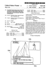
[57]
[22] Filed;
A channel number data entry system for a television
receiver employing a numeric keyboard allows the
51
Mar. 5, 1990
ABSTRACT
Int. c1.5 ...................... .. H04N s 44- HO4B 11 00
Selection °f cable Channels having Channel hhmhers
iszi US. (:1. ............................... .. 45s//1§1- 358/1911
greater than 99’ with“ the use Of a Separate ENTER
’
[58]
455/603;
or 100s key. Speci?cally, if a predetermined unused or
Field of Search ................... .. 358/194.1- 455/151
invalid channel number’ Such as 00’ is entered, the" the
455/352’ 353 60?;
on-screen display message l_.is generated, and a three
’
digit channel entry mode is enabled. If a valid and used
two digit channel number is entered, then a two digit
’
.
[56]
References Clted
U.S. PATENT DOCUMENTS
channel entry mode is enabled. In both modes, the de
sired channel is tuned upon receipt of the ?nal digit of
3,943,451
4,162,513
3/1976
7/1979
Stoddard ........................... .. 325/464
Beyers, Jr. et al. ............... .. 358/191
4,386,436
5/1983 Kocher et a1. .................... .. 455/151
RF IN
%
100
WA
TUNER
l
\ ASSEMBLY —‘
9 Claims, 3 Drawing Sheets
130
'’
102
the channel hhmheh
106
AUDIO SIGNAL
PROCESSOR
'
+
VIF AND SIF
103
\-
I
To
SPEAKER
‘ 8
V AMPLIFIERS AND JO
DETECTORS
‘03
+
104
122
j
TUNER
VIDEO SIGNAL
CONTROL
UNIT
PROCESSOR
k
,
i
To
KINE DRIVERS
1 1 1
i;
JIBS J
123
ON-SCREEN
V
DISPLAY
UNIT
80
<
‘6%
VERT
‘l
SYNC
HORIZ
H :gKE
|—>
V
1+ DEFLECTION
SEPARATOR J1’
UNIT
170 J
V
CPU
‘
LOCAL
‘
1 13
KEYBOARD
J ‘8
‘R
RECElVER
1 19
_,/
<
1 12
RON
._/
120
[3'3A
U U
E! El
RAM
D U
1 10
CONTROL
MICROPROCESSOR
El 1:]
128
US. Patent
May 28, 1991
Sheet 1 of 3
5,020,140
130
RE IN $100
D/A
_
J
T’
I02
TONER
A
106
_/
AUDIO SIGNAL
SPEAKER
+
A‘
BAND
To
PROCESSOR
\ ASSEMBLY
103
I
_
>
‘03
VIF AND SIF
AMPLIFIERS AND
J08
DETECTORS
VI04
+
I2.2
/
TUNER
VIDEO SIGNAL
CONTROL
UNIT
PROCESSOR
. TO
I<INE DRI vERS
III
it
I
ON
_
185 J
I23
L/
_
v
SCREEN
,
_
__,
DISRLAY
N'T
H
U
180
160
-‘/ vERT
<———
<
HORIZ
L
YOKC
F’
¥
SYNC
-\L> DEELECTION
SEPARATORJi’
1
UNIT
I70)
4
LOCAL
KEYBOARD
CPU
1 ‘8
./
113
_,/
<--
‘R
RECEIVER
112
ROM
TO
I28
_-/
CONTROL
MICROPROCESSOR
-/
I20
D U
110
[1 U
[3 U
RAM
II9
.2
US. Patent
May 28, 1991
Sheet 2 of 3
5,020,140
200
I
2
3
2&1
4
5
6
7
8
9
O
210
j
230
j
VOLUME
DOWN
220
J
VOLUME
_
ON/OFF
Fig. 2
Up
US. Patent
May 28, 1991
Sheet 3 of 3
5,020,140
300
310
RECEIVE
DIGIT
385
NO
1ST
DIGIT
\?
YEs
2ND
NO
DIGIT
DIsRLAY
o
_
0N scREEN
390
330
YJ
CLEAR
LEADING zERo
FLAG
1
SET
LEADINr zERo
Hi6
LEADING zERD
FLAG SET
ENABLE
E40
360
2-DIGIT
DISPLAY
ENTRY MDDE
10N scREEN
J
ENAi E
-
L
ENTRY MODE
‘
I
EXIT TO
REMAINDER
OF PROGRAM
370
5,020,140
1
2
than 99. Third, the cost and complexity of the keyboard,
keycode encoding and keycode decoding is increased
THREE DIGIT CHANNEL ENTRY SYSTEM
by the addition of the ENTER key. Fourth, it requires
CROSS REFERENCE TO A RELATED
APPLICATION
an additional key on keyboards which in recent years
have become more and more crowded as new features
have been added. For example, the keyboard of the
The subject application Ser. No. 489,392, ?led Mar. 5,
1990, is ‘related to a copending US. patent application
RCA CRK-SS remote control unit includes 80 keys.
bearing attorney’s docket number RCA 85,631, and
Adding an ENTER key to such complex keyboards is
undesirable, in that a user may have to search among all
assigned to the same assignee as the present invention.
10
FIELD OF THE INVENTION
The subject application concerns the ?eld of televi
sion receivers having channel selection capability in
those keys for the additional ENTER key.
In the second of the known prior three-digit channel
selection systems, a remote control unit includes a
“1005” key. The operation of the 100s key enables a
cluding direct entry of digits.
three digit channel number entry mode, by causing the
entry of the digit 1 in the leftmost place of the three
BACKGROUND OF THE INVENTION
digit channel number. Such a remote control unit is
Broadcast television channels in the United States are
manufactured by Magnavo-x Corporation and bears
assigned channel numbers between 2 and 83, inclusive.
Until recently the cable television channel numbering
the above-mentioned feature of an immediate reaction
model number URl 1 lMX. This approach also exhibits
system differed from the broadcast television channel
numbering system, in that cable television channels
of the television receiver by tuning a channel upon
receipt ofthe last digit entered by the viewer. However,
were numbered from 2 to 99. Despite this difference, all
broadcast television channels and cable television chan
it has the three other disadvantages discussed above
with respect to the separate ENTER key.
nels could be selected by entering, at most, two digits
via a keyboard, mounted on the television receiver 25
itself, or on a remote control unit. This limit of two
SUMMARY OF THE INVENTION
It is herein recognized that it is desirable to provide a
channel selection system for a television receiver which
digits per channel number has allowed the development
of television receivers in which the tuner is controlled
to select the desired channel immediately upon receiv
is capable ofselecting channels having channel numbers
greater than 99, which system does not require the use
of either an ENTER key or a lOOs key, and which will
ing the second digit of the channel number. The RCA
CTC'l40 color television receiver chassis, manufac
tured by Thomson Consumer Electronics, Inc., Indian~
apolis, Ind., is an example of such a system.
Recently in the United States, frequency space has
tune a channel corresponding to a desired two digit
channel immediately upon entry of the second digit.
According to the invention, a keyboard system having
three-digit channel number dataentry capability is re
been allocated for cable television channels which are
numbered in excess of 99, thereby requiring a three
sponsive to the reception of an invalid or unused chan
digit keyboard data entry system. The Electronics In
. nel number for entering a mode in which cable channels
dustries Association (EIA) has recommended the fol
greater than 99 may be tuned. If, however, a two digit
channel number which is valid and used is received,
then tuning is caused to occur immediately after the
entry of the second digit of the channel number.
lowing numbering system for cable channels.
CABLE
CHANNEL #
65-89
90—94
95-99
l00~l39
PICTURE
CARRIER FREQUENCY
BAND
3l3.25 MHz-613.25 MHz
619.25 MHz-643.25 MHz
(historically called A-l to A-5)
649.25 MHz-885.25 MHz
UHF
UHF
Low VHF
UHF
Cable channel numbers 95 to 97 reside within the
commercial FM radio broadcast band (88 MHz-108
MHz) in the United States, and are usually unused be
cause of interference problems which may occur be
tween the desired television signals and the undesired
FM radio signals.
Two prior three-digit channel selection system are
known. In the ?rst of these known systems, the key
board includes an ENTER key for signaling the com
pletion of a channel number entry. Such a system is
known from the MBC-30O remote control unit manu
BRIEF DESCRIPTION OF THE DRAWING
45
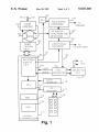
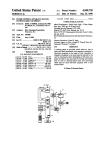
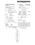
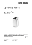
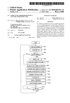
FIG. 1 shows, in block diagram form, an apparatus
suitable for practicing the invention.
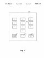
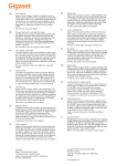
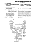
FIG. 2 shows the keyboard of a remote control unit
suitable for use with the invention.
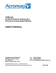
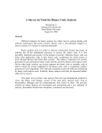
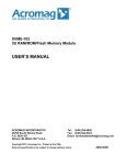
FIG. 3 is a flowchart showing a portion ofthe control
program of the controller of FIG. 1.
DETAILED DESCRIPTION OF THE
EMBODIMENT
Referring to FIG. 1, a television receiver includes an
RF input terminal 100 which receives radio frequency
(RF) signals and applies them to a tuner assembly 102.
Tuner assembly 102 selects and ampli?es a particular
RF signal under control of a tuner controller 104 which
provides a tuning voltage via a wire 103, and band
factured by Zenith Corporation. There are four disad
vantages to this approach. First, viewers have become
switching signals via signal lines represented by the
accustomed to the above-mentioned immediate reaction
of the television receiver in tuning a channel upon re
Tuner assembly 102 converts the received RF signal
to an intermediate frequency (IF) signal and provides an
IF output signal to video (VIF) and sound (SIF) ampli
?er and detector unit 108. VIF/SIF ampli?er and de
tector unit 108 ampli?es the IF signal applied to its input
terminal and detects the video and audio information
contained therein. The detected video information is
ceipt of the last digit entered by the viewer. This desir
able feature is lost in a system which employs an
ENTER key. Second, operation of the ENTER key
undesirably adds a separate keystroke to the selection of
all channels, requiring three keystrokes to select most
channels, and four keystrokes to select channels greater
broad double-ended arrow 103’.
applied as one input of a video processor unit 122. The
3
5,020,140
4
detected audio signal is applied to an audio processor
nel is tuned upon receipt of the ?nal digit ofthe channel
106 for processing and ampli?cation before being ap
plied to a speaker (not shown).
Video signal processor 122 supplies a composite
number.
video signal to a sync separator unit 160 which pro
duces vertical (V) and horizontal (H) synchronizing
signals at respective outputs. The horizontal and verti
cal synchronizing signals are applied to a horizontal and
vertical deflection unit 170 for generating scanning
control signals for application to the yoke windings of a
picture tube assembly (not shown).
Tuner controller 104 (which maybe within control
microcomputer 110) generates the tuning voltage and
bandswitching signals in response to control signals
The ?owchart of FIG. 3 shows a portion of the key
board decoding routine of the control program of mi
croprocessor 110. The purpose of the portion of the
routine shown in FIG. 3 is to detect the unique two digit
code which causes the enabling of the three digit chan
nel entry mode. The usual keycode decoding and dis
play functions are performed in another portion of the
O keyboard decoding routine of the control program of
microprocessor 110. The keycode decoding and display
functions are not shown in FIG. 3 because they are
known per se and need not be described here.
The routine of FIG. 3 is executed each time a key
applied from a system control microcomputer (pC) 110.
5 code is received. The routine is entered at step 300 and
The terms "microcomputer” and “microprocessor", as
used herein, are equivalent. It is also recognized that the
control function of microcomputer 110 may be per
keyboard 118, at step 310. At step 315, a check is made
to determine if the received digit corresponds to the
receives a digit from IR receiver 119, or from local
numeral 0. If so, then the program advances to step 320,
formed by an integrated circuit especially manufactured
for that speci?c purpose (i.e., a “custom chip”), and the 20 at which a check is made to see if this digit is the ?rst
term “controller", as used herein, is also intended to
include such a device. Microcomputer 110 receives
user-initiated commands from an infrared (IR) receiver
119 and from a “local” keyboard 118 mounted on the
digit received of a multidigit channel number. In the
subject system, channel numbers less than 10 are en
tered beginning with a leading zero. That is, channel 9
(RAM) 120. RAM 120 may be either internal to, or
external to, microprocessor 110, and may be of either
is entered as 09. Therefore, if the ?rst digit received is
the numeral 0, then the yes path is taken from step 320
to step 325. At step 325, the message O_is caused to be
displayed on the display screen. That is, if the ?rst digit
received is the numeral 0, the received digit may be
either the leading zero of a two digit channel number
less than 10, or the leading zero of the code 00 which
enables the three digit channel number entry mode.
the volatile or non-volatile type. The term “RAM" is
also intended to include electrically-erasable program
At step 330, a data bit in a memory location, called
the leading zero flag, is set. The program then advances
mable read only memory (EEPROM). One skilled in
the art will recognize that if volatile memory is utilized,
to step 340 wherein the 2-digit channel number entry
that it may be desirable to use a suitable form of standby
power to preserve its contents when the receiver is
remainder of the keyboard decoding routines.
television receiver itself. IR receiver 119 receives IR
transmissions from remote control transmitter 128. Mi
crocomputer 110 includes a central processing unit
(CPU) 113, a program memory (ROM) 112, and stores
channel-related data in a random-access memory
mode is enabled. At step 380, the program exits to the
If, at step 320, the current digit is not the ?rst digit
received, then the no path is taken to step 345. At step
345, a check is made to see if the current digit is the
Microprocessor 110 may also include an on-screen
second digit received. If not, it must be the third digit
display unit (OSD) 185 for generating auxiliary signals
received, and the program must already be in the three
suitable for displaying indicia, such as characters, for
digit channel entry mode. Accordingly, if the current
display on the display screen of the picture tube. Alter
digit is not the second digit, the no path is taken from
natively, on-screen display unit 185 may be external to
step 345, and the routine is exited. If the current digit is
microprocessor 110.
The television receiver described thus far is known 45 the second digit received, then the yes path is taken to
step 350, at which point the state ofthe leading zero flag
from the RCA CTC-l40 color television receiver man
is checked. If the second digit is the numeral 0, but the
ufactured by Thomson Consumer Electronics, Inc.,
?rst digit was not the numeral zero (for example, chan
Indianapolis, Ind.
.
nel number 10), then the no path will be taken from step
Keyboard 200 of FIG. 2 includes a VOLUME
DOWN key 210, a VOLUME UP key 220, an ON/ 50 350 to step 340, and the two digit cable channel selec
turned off.
OFF key 230, and a 0-9 numeric keypad, generally
designated 240, for entering numeric data, such as chan
nel number.
The present invention is directed to a channel number
data entry system for a television receiver employing a
numeric keyboard, which system allows the selection of
cable channels having channel numbers greater than 99,
without the use of a separate ENTER or lOOs key.
Speci?cally, if a predetermined unused or invalid two
tion mode will be enabled. If, however, the currently
received digit is the numeral 0, and the leading zero ?ag
is set (indicating that the first digit received was also the
numeral 0), then the program advances to step 360 at
which the message 1__caused to be displayed, and the
3-digit channel number entry mode is enabled at step
370. The program is then exited at step 380 to the re
mainder of the keyboard decoding routines, known per
se.
Step 385 is reached directly from step 315 for all
digit channel number, such as 00, is entered, then the 60
digits received which are other than the numeral 0. If
on-screen display message 113 _is generated, and a three
the current non-zero digit is not the ?rst digit received,
digit channel entry mode is enabled. Another invalid
it should have no effect upon the state of the leading
zero flag. In that case, the no path is taken from step 385
for television because they reside in the commercial 65 to the exit at step 380. If, however, the current nonzero
digit is the ?rst digit received, then it cannot form part
broadcast FM radio band. Ifa valid and used two digit
of the special code 00 which triggers entry into the
channel number is entered, then a two digit channel
three digit channel entry mode. In that case, the yes
entry mode is enabled. In both modes, the desired chan
channel number in the United States is channel 01. As
noted above, cable channel numbers 95 to 97 are unused
5
5,020,140
path is taken from step 385 to step 390 at which the
leading zero ?ag is cleared, the two digit channel entry
mode is then enabled (step 340), and the routine is ex
ited. As noted above, the remainder of the keyboard
decoding routines (not shown) accessed via step 380
LII
provide for the display of the entered digits on the
display screen in a known manner via the OSD cir
cuitry.
When a user wishes to enter the cable channel num
ber 135, apparatus in accordance with the subject inven
tion performs as follows. The user would enter the
unique code 00 in order to enable the three digit channel
entry mode. The OSD circuitry would cause the dis
play of O_in response to the entering of the leading zero
by the user. The display would then change to l_in
response to the entering of the second zero. The display
would show 1 3_in response to the entering of the digit
3, and l 3 5 in response to the entering of the last digit.
Immediately after receiving the ?nal digit of the three
digit channel number, in this example the numeral 5,
control microprocessor 110 causes tuner assembly 102
to tune to cable channel 135.
It is herein recognized that the addition of an.
ENTER key or 100s key to keyboard of the remote
control unit may require the modi?cation of the control
program of both the remote control unit (to detect,
process and transmit the new keycode), and the control
program of the controller in the television receiver (to
receive, decode and process the new keycode).
3O
The subject channel number data entry system de
scribed above avoids the necessity of modifying the
control program of the remote control unit, because the
invention resides in the television receiver and not in
the remote control unit. As a result of the fact that no 35
modi?cation of the remote control unit is necessary,
existing remote control units may be used when practic
ing the invention.
Further advantages of the present invention are that
keyboard complexity is not increased, the cost of adding 40
the additional key is saved, and the cost modifying the
control program of the remote control unit is saved.
The term consumer electronic equipment, as used
herein, includes television receivers and radios. The
term television receiver, as used herein, includes televi 45
sion receivers having a display device (commonly
known as television sets) and television receivers with
out a display device, such as VCRs.
It should be noted that while the code 00 was used in
the above-described embodiment, any invalid or unused
two digit channel number may be used to cause entry
into the three digit channel entry mode, if the code
detection routine of FIG. 3 is modi?ed accordingly.
What is claimed is:
6
said control means detecting the generation of one of
a two digit invalid channel number and a two digit
unused channel number, and operating in said sec
ond mode in response thereto.
2. Channel selection apparatus for a television re
ceiver, comprising:
keyboard means including a plurality of keys for
generating digits of two and three digit channel
numbers when said keys are activated by a user;
control means coupled to said keyboard means for
receiving said digits and for generating a tuning
control signal in response thereto;
said control means operating in a ?rst mode to gener
ate said tuning control signal upon receiving the
second digit of one of said two digit channel num
bers, and operating in a second mode to generate
said tuning control signal upon receiving the third
digit of one of said three digit channel numbers;
said control means detecting the sequential genera
tion of the digits O0 and operating in said second
mode in response thereto.
3. The apparatus of claim 2 further comprising:
means, coupled to said control means, for generating
character signals suitable for display on a display
screen, said control means causing said character
generating means to generate a character signal
corresponding to the numeral 1 in response to the
detection of said sequential generation of the digits
0O.
4. Channel selection apparatus for a television re
ceiver, comprising:
keyboard means including a plurality of keys for
generating digits of two and three digit channel
numbers when said keys are activated by a user;
control means coupled to said keyboard means for
receiving said digits and for generating a tuning
control signal in response thereto; and
said control means operating in a ?rst mode to gener~
ate said tuning control signal upon receiving the
second digit of one of said two digit channel num
bers, and operating in a second mode to generate
said tuning control signal upon receiving the third
digit of one of said three digit channel numbers;
said control means detecting the sequential genera
tion of two predetermined digits, and operating in
said second mode in response thereto.
5. The apparatus of claim 4 wherein said two prede
termined digits correspond to an invalid channel num
ber.
6. The apparatus of claim 5 wherein said invalid chan
nel number is channel number 00.
7. The apparatus of claim 4 wherein said two prede
1. Channel selection apparatus for a television re 55 termined digits correspond to an unused channel num
ber.
.
ceiver, comprising:
keyboard means including a plurality of keys for
generating digits of two and three digit channel
numbers when said keys are activated by a user;
control means coupled to said keyboard means for
receiving said digits and for generating a tuning
control signal in response thereto;
said control means operating in a ?rst mode to gener
ate said tuning control signal upon receiving the
8. The apparatus of claim 4, further comprising:
means, coupled to said control means, for generating
character signals suitable for display on a display
screen, said control means causing said character
generating means to generate a character signal
corresponding to the numeral 1 in response to the
detection of said two predetermined digits.
9. Channel selection apparatus for a television re
'
second digit of one of said two digit channel num 65 ceiver, comprising:
keyboard means including a plurality of keys for
bers, and operating in a second mode to generate
said tuning control signal upon receiving the third
generating digits of two and three digit channel
digit of one of said three digit channel numbers;
numbers when said keys are activated by a user;
7
5,020,140
control means coupled to said keyboard means for
receiving said digits and for generating a tuning
control signal in response thereto;
said control means operating in a ?rst mode to gener
ate said tuning control signal upon receiving the 5
second digit of one of said two digit channel num
bers, and operating in a second mode to generate
said tuning control signal upon receiving the third
digit of one of said three digit channel numbers;
8
number, and operating in said second mode in re
sponse thereto; and
means, coupled to said control means, for generating
character signals suitable for display on a display
screen, said control means causing said character
generating means to generate a character signal
corresponding to the numeral 1 in response to the
detection of said one of an invalid channel number
said control means detecting the generation of one of 10
and an unused channel number.
*
an invalid channel number and an unused channel
20
25
35
45
55
*
*
*
*