1
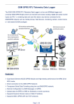
PGMⅢ Programmable Ethernet Control System
User Manual
V1.2
CREATOR CORPORATION
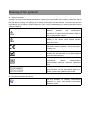
Meaning of the symbols
■ Safety Instruction
Symbols are used in the Manual and devices, referring to the possible risk to users or others,as well as
the damage to property, for helping you to safely and properly use the devices. The instruction and the
implications are as follows. Please make sure your correct understanding of these instructions before
using the Manual.
To remind user to conduct according to the
attached
operation
and
maintenance
instructions. If ignore these information, death or
injury could possibly happen.
To remind the user that the risky uninsulated
voltage in the device could caused electric
shock to human.
CE authentication indicates the product is in line
with the EU safety regulation, and for assurance
of safety use.
SGS Authentication indicates the product has
reached the QC standard of the global-biggest
Swiss universe surveyor.
This product has acquired the ISO9001
International
Quality
Authentication
(Authentication authority: Germany Rheinland
TUV)
Caution: To avoid electric shock, please don't
open the case, nor put the useless parts in it.
Please contact with qualified service staff.
■
General Information Instruction
List the situation of causing unsuccessful
operation or setup, and relevant information
needed to notice.
Important Notices
Caution
To ensure the device in reliable use and
personal safety, please abide by the following
items when in installation, use and maintenance:
Notice in installation
◆ Please DO NOT use the product in following
places: the places with dust, oily smoke,
electrical conductive dust, corrosive gas,
inflammable gas; the places with high
temperature, due, rain and wind exposures; the
places endangered by shock and vibration.
Electric shock, fire and incorrect operation could
also cause damage and deterioration to the
product.
◆ When conducting screw drilling and wiring
process, DO NOT let metal irons and wire lead
drop into the controller and air vent, which could
possibly cause fire, failure and accidental
operation.
◆ After finishing the installation, it is necessary
to ensure there is no foreign matter including the
packing material like contact paper on the
ventilation surface, otherwise, it could cause
poor heat dissipation while running, as well as
fire, failure and accidental operation.
◆ Avoid conducting wiring and plugging in/out
cable socket with electricity, otherwise, electric
shock, circuit damage could easily happen.
◆ Installation and wiring should be firm and
reliable. Poor contact could cause malfunction.
◆ With regard to the application situations with
strong interference, shielded cable should be
used for the input and output of HF signal, to
improve the anti-interference performance of the
system.
Note in Wiring
◆
Installation and wiring shouldn't be
conducted until external electric power is cut off,
otherwise, electric shock or device damage could
happen.
◆ The product is grounded by the earth lead of
the power cable. To avoid electric shock, the
earth lead is necessary to be connected with the
ground. Before making connection with the
output end or input end of the product, please
ensure it is correctly grounding.
◆
Upon finish wiring, remove the sundries.
Please cover up the terminal plate for avoiding
electric shock.
Note for Operation and Maintenance
◆ Please DO NOT touch the terminal when
with electricity, otherwise, electric shock could
happen.
◆ Don't clean up and screw the terminal tight
before power is off. Such operation could cause
electric shock when with electricity.
◆ Please turn off the power before connecting
or disconnecting the communication signal cable,
peripheral modules or control units, otherwise,
device could be damaged and accidental
operation could happen.
◆ Please DO NOT disassemble the device, so
as to avoid internal electric components damage.
◆ It is necessary to read through the Manual
and fully ensure the safety, before altering the
program, trial running, starting and stopping
operation.
Note for declaration of the worthless
When declaring of worthless, please note
◆
Explosion of electrolytic capacitor on the
circuit board could happen when burning it.
◆ Please classify and dispose it. Don't dispose
it into household garbage.
◆
Please deal it as industrial waste, or in
accordance with local environmental protection
regulation.
Forward
User’s Manual for PGMIII Programmble Ethernet Control System mainly introduces the operation
manner, primary parameters and trouble shootings of PGMIII.
The Manual serves as user's operation instruction only, rather than for maintenance service
purpose. Since the date of release, any function or relevant parameter alteration will be provided in
supplement instruction. Please refer to the manufacturer or dealers for inquiry.
CREATOR Electronics own the copyright of the Manual. Without permission, any unit or person shall
not take part or total of the Manual for business purpose.
The copyright of the Manual is protected by Copyright Law of People’s Republic of China and other
Intellectual Property Law. Without written permission, any copy or distribution is prohibited.
Index
Chapter One ,General Introduction........................................................................................................................ 1
1.1
Main Features.............................................................................................................................................. 1
1.2
Controller Installation.................................................................................................................................. 1
Chapter Two,Detailed Controller Specifications................................................................................................... 2
2.1
Front & the rear Panel................................................................................................................................. 2
2.2 Interfaces Introduction....................................................................................................................................4
2.2.1 COM Pins introduction.................................................................................................................4
2.2.2 CR-NET Connection.................................................................................................................... 4
2.2.3 CR-LINK Connection....................................................................................................................4
2.2.4 USB Interface................................................................................................................................ 4
2.2.5 Change the controller’s MAC address...................................................................................... 5
Chapter Three,Receiver........................................................................................................................................... 6
3.1
CR-WF10 Wireless Access Point..............................................................................................................6
3.1.1 CR-WF10 Settings........................................................................................................................7
3.1.2 System Connection Diagram....................................................................................................12
3.1.3 Cascading and Ethernet Connection Diagram......................................................................13
3.2
Wireless One-way Receiver: CR-RFA................................................................................................... 13
3.2.1 How to use...................................................................................................................................13
Chapter Four,Connection Diagram.......................................................................................................................14
4.1
System Connection Diagram................................................................................................................... 14
Chapter Five,IR Emitting Probe............................................................................................................................ 15
5.1
Features.......................................................................................................................................................15
5.2
Connection instruction...............................................................................................................................15
Chapter Six,Extension Cards................................................................................................................................ 16
6.1
D/A Conversion Card.................................................................................................................................16
6.1.1 Features....................................................................................................................................... 16
6.1.2 External Input.............................................................................................................................. 16
6.1.3 Operation Instructions............................................................................................................... 16
Chapter,Software Introduction...............................................................................................................................18
7.1 Think Control 1.0 Programming Software............................................................................................. 18
7.2 Think Control 1.0 Installation................................................................................................................... 18
7.3
jdk1.4 Installation....................................................................................................................................... 19
7.4
Set up the correct path jdk....................................................................................................................... 20
7.5
Uninstallation.............................................................................................................................................. 21
7.6
Codes organization and Controller Functions.......................................................................................21
7.6.1 Codes Organization.................................................................................................................. 21
7.6.2 Controller Functions..................................................................................................................23
7.7
Programing..................................................................................................................................................29
7.7.1 Build a new project....................................................................................................................29
7.7.2 Add device..................................................................................................................................29
7.7.3 Add event....................................................................................................................................31
7.7.4 IR Learning.................................................................................................................................. 32
7.7.5 Import IR Control Codes........................................................................................................... 35
7.7.6 Editing the program....................................................................................................................36
7.7.7 Compile the project.................................................................................................................... 37
7.8
Upload the program to the CR-PGMIII...................................................................................................37
7.9
Project Sample........................................................................................................................................... 38
7.9.1 Control the built-in relay modules on the controller..............................................................38
7.9.2 Cascading and Module calls.................................................................................................... 39
7.9.3 Wall-mounted Programmable keyboard................................................................................. 40
7.9.4 Lighting and Sound Control...................................................................................................... 41
7.9.5 Interlock of 2 ways relay............................................................................................................42
7.9.6 Repeat button pressing without affecting delay timer execution........................................43
7.9.7 Control the matrix switchers..................................................................................................... 43
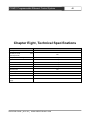
Chapter Eight,Technical Specifications............................................................................................................... 46
Chapter Nine,General Trouble Shootings........................................................................................................... 47
1
PGMⅢ Programmable Ethernet Control System
Chapter One ,General Introduction
CR-PGMIII is a patent Programmable
Ethernet Controller launched by CREAOTOR. It
has applied 32bit 667MHz ARM11 CPU, 256M
RAM, and 1G Flash Memory.
The CR-PGMIII Programmable Ethernet
Controller
provides
multi-types
controlling
interfaces: 3 types of network controlling ports:
CR-NET, CR-LINK and Ethernet; IR, I/O, RELAY,
and COM Ports, etc.
Advanced IC Technology has been applied to
provide high-speed accurate integrated control;
and the Open Programming UI ensures the
easiness of programming for various complicated
controlling functions.
1.1
Main Features
◆ 3 types of network
CR-NET,CR-Link,Ethernet;
◆USB2.0
interface;
communication
◆built-in IR Learning module,
diagnosing and maintenance;
easy
for
◆ both local and remote control supported;
◆ Universal power (AC100~240V),
1.2
Controller Installation
The CR-PGMⅢ programmable Ethernet
Controller can be installed onto standard 19 inch
rack. One pair of racking frames has been
provided along with the machine. Please refer to
the following draft for the guidance:
◆ Elegant design integrated with both popularity
and fashion
◆ ARM11 CPU,256M DDR RAM,1G Flash
Memory;
◆ 667MHz 32bit powerful CPU;
◆ 8 independent programmable IR Control
modules, supporting multiple same or different
equipment through IR;
◆ 8 independent programmable RS-232/422/485
Controlling interfaces; allowing users to program
and set multiple types of controlling protocols and
codes
◆ 8 low-current replay modules;
◆ 8 digital I/O Modules
CREATOR CHINA 2011-03
programming
communication:
WWW.CREATOR1997.COM
PGMⅢ Programmable Ethernet Control System
2
Chapter Two,Detailed Controller
Specifications
2.1 Front & the rear Panel
CR-PGMⅢ Front Panel:
CR-PGMⅢ Rear Panel:
1) POWER——Power Indicator
2) RS-232/422/485——COM data
communication indicator
Indicates the data communication status of
the 8 COM interfaces: when there is data sending
or receiving, the corresponding indicator will be
on. The “TX” is for data sending indication, and
the “RX” is for data receiving indication.
3) ACTIVE——Status Indicator
4) RESET—— Reset Button
When the controller is into an abnormal status
CREATOR CHINA 2011-03
due to being downloaded with wrong program (a
infinite loop for example), the RESET button can
be pressed to erase the wrong program.
Operation Instruction: First power off the
controller; then power on the controller while
press and hold the RESET button. The “beep”
sound will start and continue. Release the RESET
button after about 7 ~8 beeps, and the wrong
program will be erased from the controller.
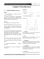
5) SENSOR—— IR Receiving Window
CR-PGMⅢ
Programmable
Ethernet
Controller provided built-in IR Learning Module,
and SENSOR can receiving the IR Signal to be
WWW.CREATOR1997.COM
PGMⅢ Programmable Ethernet Control System
learned for controlling.
3
14 ) CR-LINK——CREATOR High-speed Bus
Interface, for extending controlling functions
6) REBOOT—— Reboot button
Press this button to reboot the system when the
controller is not functioning.
7) DATA—— Data Signal Indicator
The indicator will be ON if the data signal
transmission is normal, or, it will be OFF
8) IR OUT—— IR Signal Indicator
Indicating 8 IR Modules status: when the
controller is sending the IR Control Signal to the
equipment to be controlled, the corresponding
indicator will be ON.
9) COM Interfaces
8 programmable two-way serial communication
DB9 (male) interfaces have been provided;
RS-232/422/485 protocols.
10) ETHERNET—— Ethernet Interface
Used to communicated with the Ethernet and the
Wifi touch panels, or to realize the Ethernet
remote control.
USB——USB2.0 Communication Interface
Connected to the PC’s USB interface to realize
various operations: such as the program
downloading, System Diagnosis, and IR Learning,
etc.
CR-NET——CR-NET Bus
CREATOR Communication Interface (Similar to
RS485) of 4-core phoenix connector type; can be
used to connecting various CREATOR external
network equipment: such as the relay box,
lighting control module, sound control module,
wireless Access Point, and wired touch panels,
etc.
IR OUT——IR Control Port
Includes 8 ways independent programmable IR
Control carrier waves to control various
equipment: such as the DVD, VCR, and MD, etc.
It’s of the 2-core phoenix connector type, and
needs to be used along with the IR Emitting
Probes: connect the IR Emitting Probe to the IR
OUT port and the other end near to the
equipment to be controlled (the distance needs to
be ≤ 15cm).
RELAY
OUT——Low-current
Relay
Control Port
Provides 8 ways low-current control function, and
can drive the load below AC 0.3A/125V and DC
0.3A/110V, DC 1A/30V. It can control the ON
and OFF of any equipment fulfilling the above
mentioned conditions to realize controlling
high-current, high-voltage load with low-current,
low-voltage controller
11) 24V Safety
12) AC 100V~240V—— System Power Supply
Power Supply for the controller: self-adaptive
AC100V~240V@ 50/60H.
DIGITAL I/O——I/O ( input / output )
interface
Provides 8 ways programmable I/O controlling
function: 5V/10mA output or 0~5V/10mA input.
13) IR OUT—— Extension IR Control Module
Slot
Extension IR Control Module can be inserted here
to extend the total IR Control Modules.
15 ) RELAY OUT——Extension Low-current
Relay Module Slot
Can extend the low-current relay module number
by inserting extension module.
CREATOR CHINA 2011-03
WWW.CREATOR1997.COM
PGMⅢ Programmable Ethernet Control System
16)DIGITAL I/O——Extension I/O Module Slot
Can extend the I/O control module number by
inserting the extension module here.
4
to the following diagram:
17) UART—— Extension COM Module Slot
Can extend the COM interface number by
inserting the extension COM module here.
18) Grounding Pole
2.2 Interfaces Introduction
During the installation and using, plugging
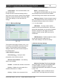
2.2.1 COM Pins introduction
Pin
Signal
and unplugging equipment while power is ON
should be avoided to reduce the risk of
malfunction of the controller due to the electric
shock caused.
2.2.3 CR-LINK Connection
Introduction
RS-485 protocol, connected along
1
RXD
with the pin 9 to be used as the
RS-485”-”
2
RXD
RS-232 protocol, receive data
3
TXD
RS-232 protocol, send data
The connection of the CR-NET equipment
supports both series and parallel connection
types. And attention should be paid to the
corresponding of the 24,D+,D-,
the following diagram:
. Please refer to
RS-485 protocol, connected along
4
TXD+
with the pin 6 to be used as the
RS-485”+”
5
GND
Signal Grounding
RS-485 protocol, connected along
6
RXD+
with the pin 4 to be used as the
RS-485”+”
7
RTS
8
CTS
RS-232
protocol,
request
for
sending
RS-232 protocol, cancle sending
RS-485 protocol, connected along
9
TXD
with the pin 1 to be used as the
RS-485”-”
2.2.2 CR-NET Connection
The connection of the CR-NET equipment
supports both series and parallel connection
types. And attention should be paid to the
corresponding of the 24,Y,Z,G. Please refer
CREATOR CHINA 2011-03
During the installation and using, plugging
and unplugging equipment while power is ON
should be avoided to reduce the risk of
malfunction of the controller due to the electric
shock caused.
2.2.4 USB Interface
The USB interface is used to communicate
with the PC during programming and diagnosis.
The connection diagram is as following:
WWW.CREATOR1997.COM
PGMⅢ Programmable Ethernet Control System
USB
PC
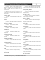
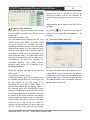
2.2.5 Change
address
PGMⅢ
Ⅲ
the
controller’s
MAC
The MAC address cannot be in conflict with
any equipment’s MAC address (the PC for
example); and it needs to be modified if the
conflict happens.
How to do it: While ensuring the controller is in
good communication with the PC, fill in the MAC
address in the box according to the following
sample. Then click the OK and reboot the
controller.
CREATOR CHINA 2011-03
WWW.CREATOR1997.COM
5
PGMⅢ Programmable Ethernet Control System
6
Chapter Three,Receiver
3.1 CR-WF10 Wireless Access
Interfaces:
Front Panel:
Point
The CR-WF10 is a wireless router with
delicate, elegant design.
The wireless AP provides the communication
between the CR-PGMIII and CREATOR Wifi
wireless touch panels to ensure the easy, flexible
and highly effective control experience.
Rear Panel:
Features
◆ Resistible to 12KV static electric shock
◆ WEP 64bit/128bit digital encryption technology
has been applied to ensure the stableness and
confidentiality of the transmission to avoid tapping
and interference.
◆ One RJ45 interface has been provided for the
connection to the CR-PGMIII or Network Switch.
High-quality CAT5 cable is recommended.
◆ Configuration Mode: AP Mode, Point to Point
Bridge Mode and Point to Multiple Point Bridge
Mode.
◆ The signal coverage can reach up to a circle
area of 15 meters radius without strong block.
The general coverage is a circle area of 10meters
radius
◆
IEEE802.11g,IEEE802.11b
supported;
standards
①
Power indicator: it will be ON if the device is
powered on, otherwise it will be off.
②
PoE
Ethernet power supply indicator: when the
Ethernet powers the device, it will be on.
③
WIRELESS
Wireless network signal indicator: when there is
wireless signal transmitting, the indicator will on,
meaning it is sending or receiving data.
④
◆ Dual-antenna to ensure the stableness of
transmission
POWER
ETHERNET
Ethernet signal indicator: when there is Ethernet
signal transmitting, the indicator will on, meaning
it is sending or receiving data.
⑤ Antenna
A pair of rotatable antenna has been provided for
CREATOR CHINA 2011-03
WWW.CREATOR1997.COM
7
PGMⅢ Programmable Ethernet Control System
being adjusted for best signal transmission
⑥
RESET
This is the reset button. There are two ways of
reset the device to the default settings: press and
hold the RESET button for 10 seconds, or, use
the web-browser based configuration tools.
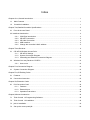
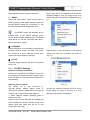
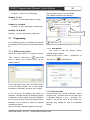
Firstly, right click on the desktop and choose the
“Network Neighbor” from the popup menu, then
choose and click “Prosperities”. Illustrated as Img.
3-1.
The RESET button will eliminate all the
settings back to the default settings, which
include all the security settings and IP. The default
value will be: IP: 192.168.1.245,login user name:
admin, Password:admin.
⑦ ETHERNET
Ethernet interface, for connection to network card,
network switch or routers. The blue color means
the connection is good, while the orange color
means the communication is going on.
Img.3-1
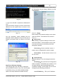
Right click the “Local Connections” on the opened
window and click the “Properties” as shown in
Img. 3-2.
⑧ DC 12V
DC power supply interface: the device is powered
by DC 12V.
3.1.1
CR-WF10 Settings
Step One: Hardware installation
Connect the CR-WIFI10’s ETHERNET port to the
PC’s network card, and connect the power supply
to the CR-WIFI 10. Then the device should be on
automatically.
Step Two: Set the right IP
The default IP of the CR-WF10 is:
192.168.1.245,the default subnet mask is:
255.255.255.0,and the default SSID is ciscosb, all
of which can be set to other value required.
1. Wired Network settings (example given in
Windows XP OS)
Power on the PC with Windows XP installed and
check whether the LAN port indicator is ON. If not,
please check and make sure the PC is well
connected to the router.
CREATOR CHINA 2011-03
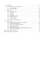
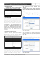
Img. 3-2
Choose the “Internet Protocols (TCP/IP) at the
popup dialog, as shown in the Img. 3-2. Then
right click and choose “Prosperities”.
WWW.CREATOR1997.COM
8
PGMⅢ Programmable Ethernet Control System
Img. 3-4
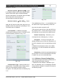
Img.3-3
Then, set the IP, Subnet Mask and the Default
Gateway in the window opened. The IP address
should
be
within
192.168.1.1
to
192.168.1.254(192.168.1.245 excluded). The
Subnet Mask is: 255.255.255.0, and the default
Gateway is : 192.168.1.245. Click “OK” to save
the settings, then click “OK” again to save the
prosperities of the Local Connections, as shown
in Img. 3-4:
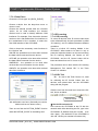
2. Verify the settings (based on Windows XP OS)
Select: “Start” --- “All Programs” --- “Accessories”,
as shown in Img. 3-5:
Img. 3-5
Follow the instructions shown in Img.3-6, type
“Ping 192.168.1.245” and press Enter. If you can
get the results as shown in the image, it means
the connection between the PC and the CR-WIFI
10 is working.
CREATOR CHINA 2011-03
WWW.CREATOR1997.COM
9
PGMⅢ Programmable Ethernet Control System
Monitor,Administration, and Status. What need to
be changed are only the Setup, Wireless, and the
Administration.
Img.3-6
3. Log in the CR-WIFI 10 (based on Windows XP
OS)
Open IE browser, and type 192.168.1.245 into the
address bar, then press Enter, as shown in the
Img. 3-7:
Img. 3-9
3.1.1.1 Setup
Img. 3-7
Use the username: admin (default) and the
password: admin (default) to log in at the pop up
window, and press Enter, as shown in the Img.
3-8:
Basic settings and network settings can be down
under this option. The interface is as shown in
Img. 3-4.
◆ Basic Setup
Basic Setting: to perform settings of Host name
and Device Name. The Host Name can be used
to access the network, and build up the DNS
through the network.
Host name:Set the controller’s name. A
proper name is suggested for easier manage.
Device Name:Set the device’s name: it can
be any name.
Img. 3-8
Step Three: Wireless Settings
The settings page of the CR-WIFI 10 will open
after procedures shown in Img. 308, and the page
is as shown in Img. 3-9, which includes setting
options as: Setup Wireless AP Mode Security
CREATOR CHINA 2011-03
◆ Network Setup
Network settings: IP can be changed under this
option.
IP Settings:Set up the law for IP assignment:
static or dynamic. The default way is static IP, and
the same default value should be kept for the
controller’s settings. The CR-WIFI 10’s IP can be
changed by the following procedures:
Local IP Address: fill in your IP address,
WWW.CREATOR1997.COM
10
PGMⅢ Programmable Ethernet Control System
e.g.: 192.168.2.1
wireless transmission is 54Mbps
Subnet Mask:fill in the Subnet Mask, such
as: 255.255.255.0
Except the above mentioned settings, all the
other value can be set as 0,which include Default
Gateway, Primary DNS and the Secondary DNS
Click “Save Setting” to save and finish the
settings.
Mixed:Self-adaptive mode
This option is recommended, then the device
can self-adjust and choose the best suitable
mode according to the network card connected.
3.1.1.2 Wireless Settings
Wireless Channel:Choose the right channel
here. The default amount of the channels is 6. For
the detailed settings, please refer to Section
3.1.1.3 in this chapter.
SSID Name:The log in name used for
wireless local network identification. Only the ID
passed the identification can access the wireless
network. As shown in the image, this device
supports 4 SSID, and the SSID name can be
customized.
SSID Broadcast:Enable should be set here
for the other devices to detect the AP.
Click “Save Settings” to finish the settings.
Img. 3-10
2, Wireless Security Settings
The wireless setup page is shown in Img. 3-10.
For setting up the wireless network the control
system, only the following items should be
changed, while other items should be kept as
their default value.
1,Basic Wireless Settings
Basic Settings:to setup the basic
prosperities of the wireless network.
Wireless Network Mode:the following
options are available:
Img. 3-11
Wireless Security:Security parameters
Disable:to disable the wireless connections
B-Only:B Mode: the max speed of the
wireless transmission is 11Mbps.
G-Only:G Mode: the max speed of the
CREATOR CHINA 2011-03
can be set here: set a key and enable WEP,
or WPA, WPA2 encryption to reject the
unauthorized access to the network. As shown
in Img. 3-12.
Select SSID:select an SSID and set its
security mode. The image shows the security
WWW.CREATOR1997.COM
11
PGMⅢ Programmable Ethernet Control System
settings for “ciscosb”.
Wireless Isolation(between SSID)
:when
it is enabled, different users within different SSID
cannot access each other to realize Wireless
Virtual Local Network. The default value is Enable,
and to improve the security level, it is
recommended to enable this option.
Img. 3-13
Wireless Isolation(within SSID)
:Clients
within this AP cannot access each other when it is
enabled, which can prevent the spreading of virus.
The default value is disabled.
Security Mode:9 different encryption
methods are provided for this AP. The WEP mode
is recommended, as shown in Img. 3-12:
The available key is from 1 ~ 4, and definition can
be made to the 4 keys respectively. All the four
keys can be used to access the AP.
There are two types of Keys: Hex and ASCII: the
key needs to be 0 ~ 9 for the Hex format, and all
the characters can be used for the ASCII format.
Default Transmit Key:Default key, and
corresponds to the following Key 1 to Key 4.
Encryption:The way of encryption: the
default is 64bits: input 10 bits Hex characters or 5
bit ASCII characters in the corresponding transmit
key.
If 128bits format has been chosen, then 26bits
characters or 13 ASCII characters are required
for the Keys.
Passphrase:Use this to generate password
by the system. It is not recommended to be used,
in stead, use your own memorable keys.
3.1.1.3 Wireless Channel Setting Rules
Img. 3-12
Authentication Type:Nothing needs to be
changed here. The default value is open system,
which is a hand-shaking method for WEP
encryption. The setting is shown as following: Img.
3-13
CREATOR CHINA 2011-03
The following aspects should be paid attention to
while setting the Wireless Channel:
1. Wireless PCs are based on WiFi802.11g or
802.11b standards, and 13 overlapping channels
are provided in wireless PC network, as shown in
the following image:
WWW.CREATOR1997.COM
12
PGMⅢ Programmable Ethernet Control System
Img. 3-14
2.Pay attention to the carrier wave: in the system,
the provided 13 overlapping channels in wireless
PC network have been divided into 3 groups, as
shown in the following image:
Img. 3-17
Management:it can be reset the user name and
password here. It is recommended to reset them
for better security condition.
Img. 3-15
3.Pay attention to the interference: the wireless
network in the system will interfere the PC
wireless network. Thus, it has to be ensured that
the CREATOR WiFi is not overlapping the WLAN
channels.
For example:
As shown in the following image, the WLAN
channel is 9, which is overlapping the group 1 and
2 of the wireless network. Thus, the first channel
of the group 0 should be chosen.
Web Access: To increase the security level, you
can use the HTTPS connection type.
Set Web HTTPS Access Wireless Web
Access as Disabled;
Set SNMP as Disabled;
Keep other values as default, and click Save
Setting to save and finish the settings.
3.1.2 System Connection Diagram
图 3-16
3.1.1.4 Administration Settings
Three options are provided here: Management,
Web Access and SNMP:
CREATOR CHINA 2011-03
WWW.CREATOR1997.COM
PGMⅢ Programmable Ethernet Control System
3.1.3
Cascading
Connection Diagram
and
Ethernet
13
3) SIGNAL——Communication indicator
When the CR-RFA receives the wireless signal
from the touch panel, the indicator will be
flashing.
4) RS-232—— Serial Port
Reserved port for the CR-RFA’s extension
functions.
3.2 Wireless One-way Receiver:
CR-RFA
The CR-RFA wireless ( RF ) one-way receiver
provides the connection between the controllers
and the one-way programmable touch panels,
which works on 433MHz, is of one-way
communication.
5) NET——4 bit network interface
It is the communication interface between the
CR-RFA and the controller, connecting to the
CR-NET interface on the controller.
6) ID CODE——Network ID
To set the CR-RFA’s network ID. Please be noted
that the Network ID has to be same as the
CR-RFA’s ID in the program written by the Control
System Builder Software.
7) ANTENNA—— Spiral antenna
3.2.1 How to use
The ID CODE setting has to be the same as
corresponding settings on the controllers, or, they
will not be able to communicate.
Interfaces:
Generally it is used while the wireless controlling
distance is relatively short (within the same room,
for example). Besides the remote control, the
special PC Serial Port software can be used to
enable sending out continuous RF control
command from the PC.
Connection:
1 ) POWER——Power indicator: will be ON
when power supply has been connected
2) ID——ID indicator
When the connection is between the CR-RFA and
the controller, the ID indicator on the receiver and
the NET ID on the controller will be ON.
CREATOR CHINA 2011-03
WWW.CREATOR1997.COM
PGMⅢ Programmable Ethernet Control System
14
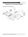
Chapter Four, Connection Diagram
4.1 System Connection Diagram
CREATOR CHINA 2011-03
WWW.CREATOR1997.COM
PGMⅢ Programmable Ethernet Control System
15
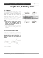
Chapter Five, IR Emitting Probe
5.1 Features
The IR Emitting Probe is mainly used to control
the equipment from the controller (such as the
DVD, VCR, etc.) It is mainly composed of an IR
emitter and a plastic case. The IR emitter has
positive and negative. While extension of the
Probe cable is required, the “Signal Conductive”
property of diode should be paid attention to.
There are many ways to find out the IR control
codes:
1、 Search from the Think Control Software:
within the ”User IR Module,” which has
included most IR Control codes for the
equipment on the market.
2、 Learn the IR Control code into the program
using the built-in IR Learning Module in the
controller.
5.2 Connection instruction
Connect the IR Emitting Probe to the IR Module
Interface on the controller and stick the other end
onto the equipment’s IR receiver, or, place the
other end within an area of less or equal 45°
within 20cm distance from the equipment’s IR
receiver.
Connection Diagram:
CREATOR CHINA 2011-03
WWW.CREATOR1997.COM
PGMⅢ Programmable Ethernet Control System
16
Chapter Six, Extension Cards
read. After the Conversion Card receives the
command, it will read and feedback the actual
voltage to the CR-PGMIII.
6.1 D/A Conversion Card
6.1.1 Features
◆ Input: 3 ways high-impedance DC input
◆ Output: 3 ways DC output
◆ Convert: Convert between Digital and Analog
Signals: can be used for sampling and controlling.
It is of 10 bit sampling accuracy, and 12 bit output
accuracy.
◆Input
◆Output
Voltage
Voltage
Range:
0V
Range:
-12V
~
~
+12V
+12V
◆The outputted voltage can be adjusted through
the software
◆ Max input voltage: +36V DC
◆ Max Output Current: 5mA
6.1.2 External Input
◆ Max Output Sampling Value: +12V
◆ Overvoltage: +36V
◆ The following is the programming instructions
for the CR-PGMIII when using the Conversion
Card:
SEND_QACAR
Void SEND_QACAR (String dev, in it channel)
Function: Send out the request of the Conversion
Card’s voltage. After the request being sent out,
the Data EVENT of the Conversion Card will be
triggered, and the voltage value will be seen there.
For the detailed example, please refer to other
functions’ BYTE_TO_INT.
Parameters
:
dev - : D/A Conversion Card Device
channel -:The device’s channel number
Sample
:
Acar_m = M:8:ACAR:192.168.1.20; //Define a
Conversion Card whose mother board number is
8
SEND_QACAR (Acar_m,1); // Read the voltage
on Acar_m’s first channel
6.1.3 Operation Instructions
◆How to control the output voltage (D/A
Conversion)
The CR-PGMⅢ controller sends out the
commands about the output voltage and channel
number to the Conversion Card. After the
Conversion Card receives the commands, it will
output the corresponding voltage
◆ Read the input voltage (A/D Conversion)
The CR-PGMⅢ controller sends out the
commands about which channel’s voltage to be
CREATOR CHINA 2011-03
BYTES_TO_INT
Int
BYTES_TO_INT
(byte[]
b)
Function: use the byte array’s first 4 bits as an int
value.
Returns
Return converted int value
:
Sample: The Conversion Card returns data: the
actual voltage of the Conversion Card = returned
WWW.CREATOR1997.COM
PGMⅢ Programmable Ethernet Control System
voltage/100.00
DATA_EVENT(mcar,2)
{
ONDATA()
{
double
tt
=
BYTES_TO_INT(DATA.Data)/100.0 //when using
SEND_QACAR to send the request, it triggers
here.
SEND_COM(COM,1,DOUBLE_TO_STRING(tt));
}
}
SEND_ACAR
void SEND_ACAR(String dev,int channel,int val)
Function: control the voltage output of the
Conversion Card.
Parameters:
dev
-
channel
:
-
:
Conversion
Device’s
Card
Device
Channel
number
val - :Analog Value (Notice: read value according
the actual external equipment. The general value
reading range is -12V ~ 12v in double type.)
Example:
acar_L = L:7:ACAR:192.168.1.20; //Define ACAR
Device with CRLINK(CAN) number of 7
SEND_ACAR( acar_L,1,-12);// Send Analog
Value -12 to lilt_L’s first channel. i.e., set the
Converter Card’s output to -12V.
CREATOR CHINA 2011-03
WWW.CREATOR1997.COM
17
PGMⅢ Programmable Ethernet Control System
18
Chapter, Software Introduction
7.1 Think Control 1.0
Programming Software
The Think Control 1.0 programming software is
designed for programming for the CREATOR third
generation controller: the CR-PGMIII.
PC OS Requirements
This programming software can run on Windows
XP, VISTA, and WIN7.
7.2 Think Control 1.0 Installation
Click Next again.
The Think Control 1.0 programming software is
available in the disk in the CR-PGMIII’s package.
It can also be downloaded from the web address
at: http://www.creator.com.cn.
The installation procedures are as following:
Double click the installer to launch the installation,
as shown in the image:
Choose your preferred language, and click Next.
Click Next:
CREATOR CHINA 2011-03
WWW.CREATOR1997.COM
PGMⅢ Programmable Ethernet Control System
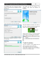
The installation path can be changed by clicking
Change. Click Next after the installation location
has been set.
19
The installer will show the progress of the
installation. Click Cancel can abandon the
installation.
Type in the shortcut’s name, then click Next.
When the installation has finished, click “Finish” to
exit. Then, a shortcut icon will be created at the
desktop, as shown in the following image:
here
We also need the JDK1.4 to compile the software
programmed, or, the following error will appear:
Make sure the displayed information is correct,
then click Next.
7.3 jdk1.4 Installation
The jdk1.4 software is both available from the
disk in the package and the CREATOR
The installation procedures are as following:
Click the jdk1.4 installer to launch the installation,
as shown in the following image:
CREATOR CHINA 2011-03
WWW.CREATOR1997.COM
PGMⅢ Programmable Ethernet Control System
20
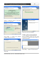
Choose “I accept the terms in the license
agreement,” then Click Next
Click Finish to finish the installation.
7.4 Set up the correct path jdk
Click Change… to choose your
installation path, then click Next
preferred
After the installation, double click Think Control
1.0’s short cut to launch the Think Control 1.0
programming software.
Click “setting” --- “Options” from the menu bar.
Click Install
CREATOR CHINA 2011-03
WWW.CREATOR1997.COM
PGMⅢ Programmable Ethernet Control System
21
7.6 Codes organization and
Controller Functions
7.6.1 Codes Organization
1 A program is consisted of the following
modules:
Every module has its own special functions: for
example, the “DEFINE_DEVICE” is used to
define a device. Each equipment involved in the
controlling program has to be defined here. It is
recommended not to change the order between
every module.
// Device definition module
DEFINE_DEVICE
Choose “environment”
// Constant define module
DEFINE_CONSTANT
// Variable define module
DEFINE_VARIABLE
// Function define module
DEFINE_FUNCTION
Click to browse the right jdk1.4 installation path.
Note: if jdk1.4’s has been installed to its
default path, nothing needs to be changed
here.
// Program initialization module
DEFINE_START
// Loop define module
DEFINE_PROGRAME
// Event define module
DEFINE_EVENT
7.5 Uninstallation
The software can be easily uninstalled from
“Start”—”Control Panel”--- “Add and Delete
Program”. All files, modules and shortcuts will be
deleted after the u installation.
2 Define Modules
DEFINE_DEVICE: Device define module
All the device definition has to be done within
this module.
DEFINE_COMBINE: Device define
module
This module is used to define multiple touch
panels in the same system.
CREATOR CHINA 2011-03
WWW.CREATOR1997.COM
PGMⅢ Programmable Ethernet Control System
DEFINE_VARIABLE: Variable define module
All the variables need to be defined here
DEFINE_CONSTANT: Constant define
module
All the constants need to be defined here
DEFINE_FUNCTION: Function define
module
All the functions have to be defined here
DEFINE_TIMER: Timer define module
All the timers should be defined here. For
some actual requirements, there might need a
timer to repeat an action on a regular timer
interval.
DEFINE_START: Program Initialization
Module
All codes here will be executed first before
the other parts in the program. This module can
be used to do the initialization jobs, such as
initializing
variables
and
execute
some
initialization operations.
DEFINE_EVENT: Even define module
All the events definition has to be done within
this module.
There are mainly three kinds of events:
◆ Button event
Syntax:the parameter can be 0, 1, or 2. When
there are 2 parameters, it means the even is
effective to the defined device name and joint
number. When there is only 1 parameter, the
event is only effective the defined device name.
When the parameter is 0, the event is effective to
all the devices.
There functions corresponding to four events:
“Press”, “Release”, “Hold” and “the whole button
procedure”. The even execution codes have to be
put into the corresponding functions.
BUTTON_EVENT([device] [JionNumber])
{
PUSH()
{
// The operation to be done when press
down the button
}
RELEASE()
{
// The operation to be done when release
the button
}
HOLD(<TIME>[,TRUE|FALSE])
{
// The operation to be done after the button
has been press down and held for a certain, or, at
a certain time interval.
}
REPEAT()
{
// The repeatedly operation to be done when
the button is pressed down. }
}
◆ Bar Event
Syntax: the parameter can be 0, 1, 2. When there
are 2 parameters, it means the event will only be
effective to the defined device and the joint
number. When there is 1 parameter, it means the
even will be effective to the defined device. When
the parameter is 0, it means the event is effective
to all devices.
LEVEL_EVENT([device] [, Jion Number])
{
// Operation to be done when the bar has
changed
}
◆ Data event
CREATOR CHINA 2011-03
22
WWW.CREATOR1997.COM
PGMⅢ Programmable Ethernet Control System
DATA_EVENT([device])
{
ONLINE()
{
// Operation to be done when received the
data online command from the device }
OFFLINE()
{
// Operation to be done when received the
data offline command from the device }
ONERROR()
{
// Operation to be done when received the
data error command from the device
23
IR_M = M:1000; //define the IR device on the
controller’s mother board
IR_M
// Send IR Code to the IR_M’s first channel
// in which,
IRCODE<“StanderIRDb:3M:CODEC:VCS3000:P
OLYCOM1:6289:6 (MNO)”> are the IR Control
codes from 3M company in the IR Code database
// CODEC type,VCS3000 Model
number,POLYCOM1 equipment to be controlled,
IR Sample number 6289’s MNO IR code
// Call the function and send out the matching IR
Code from the IR Code database
SEND_IRCODE(IR_M,1,IRCODE<“StanderIRDb:
3M:CODEC:VCS3000:POLYCOM1:6289:6
(MNO)”>);
}
ONDATA()
7.6.2.2 ON_RELAY
{
void ON_RELAY(String dev,int channel)
Function: turn on the relay module
// Operation to be done when received the
data from the device }
}
DEFINE_PROGRAME: Loop Module
When the program starts to run, the codes here
will be executed repeatedly. Some monitoring
operations can be realized here to monitor the
device’s status.
Parameters:
dev - :relay device
channel - : device’s channel number
7.6.2 Controller Functions
Sample:
RELAY_M = M:1000:RELAY; // define the relay
with the motherboard number of 1000
ON_RELAY(RELAY_M,2); // turn on the relay
with the motherboard number of 1000
Controller functions are used to realize different
functions of the controller.
7.6.2.3 OFF_RELAY
7.6.2.1 SEND_IRCODE
Void
SEND_IRCODE(String dev,int channel,String str)
Function: send IR Data
Parameters:
dev - :IR Equipment
channel - :Equipment Chanel number
str - :IR Data HEX String
Sample:
CREATOR CHINA 2011-03
void OFF_RELAY(String dev,int channel)
Function: turn off the relay
Parameters:
dev - :relay device
channel - :device channel number
Sample
RELAY_M = M:1000:RELAY; //define the
relay with the motherboard number of 1000
OFF_RELAY(RELAY_M,2); // turn off the relay
with the motherboard number of 1000
WWW.CREATOR1997.COM
PGMⅢ Programmable Ethernet Control System
7.6.2.4 SET_COM
void SET_COM(String dev,
int channel,
long sband,
int databit,
int jo,
int stopbit,
int dataStream,
int comType)
Function: Setup the COM interface
Parameters:
dev - :device name
channel - : Device channel number
sband - :Baud Rate
databit - :data bit 1~8
jo - :Parity 0:none,1:Odd number,2:even
number,3:Mark,4:space
stopbit-:Stop bit 10,15,20, corresponding to
10=1,15=1.5,20=2
dataStream - :Data flow:0:无,1:xon/xoff,2:
hardware
comType - :COM interface communication type
232,485,422; default value is 232
Sample:
Com_m = M:1000:COM; //define the COM
interface with the motherboard number of 1000
// setup the COM interface’s first channel (i.e.
define the first COM interface with the
motherboard number of 1000)
// Baud rate is 9600,Data bit is 8,no parity, Stop
bit is 1,No data flow, communication type is 232
SET_COM(Com_m,1,9600,8,0,10,0,232);
7.6.2.5 SEND_COM
void SEND_COM(String dev,int channel,
String str)
Function: Com interface data sending
Parameters:
CREATOR CHINA 2011-03
24
dev - :Com interface device
channel - :Device channel number
str - :Com interface data, support two formats:
1:Direct transmit string data ( send the string as it
is to the Com interface)
2:Conversion into Hex string (when it encounters
string starting with 0x or 0X, the string will be
converted into Hex format and be sent. For
example: if 0x3132 is sent, the COM interface will
receiver the string of “12”).
Example:
Com_m = M:1000:COM; // define the COM
interface with the motherboard number of 1000
SEND_COM(Com_m,1,”1234”); // send the string
“1234” to the first channel of the mother board
SEND_COM(Com_m,1,”0x31323334”); // send
the string “1234” to the first channel of the
motherboard
7.6.2.6 SEND_IO
void SEND_IO(String dev,int channel,int val)
Function:Control I/O interface
Parameters:
dev - :io device
channel - :Device channel number
val - :data 0 | 1
Example:
Io_m = M:1000:IO; // define the I/O interface with
the mother board number of 1000
SEND_IO(Io_m,1,0); // output low electrical level
to the first channel of Io_m
7.6.2.7 READ_IO
int READ_IO(String dev,int channel)
Function:Control I/O interface
Parameters:
dev - :io device
channel - :Device channel number
Return:return the electrical level status of the
“channel” in the I/O interface: it is 0 or 1. Other
value is viewed as false.
WWW.CREATOR1997.COM
PGMⅢ Programmable Ethernet Control System
25
Example:
Io_m = M:1000:IO; // define the I/O interface with
the mother board number of 1000
int iostate =READ_IO(Io_m,1); // read the first
channel’s status of Io_m
dev - :Conversion Card device
channel - :Device channel number
val - : Analog value (Note: get the value
according the actual external device. The general
range is -12V ~ 12V of double type)
7.6.2.8 SEND_LITE
Example:
acar_L = L:7:ACAR; // define the ACAR device
with the CRLINK(CAN) number of 7
SEND_ACAR( acar_L,1,-12);// send analog value
-12 to the first channel of lilt_L, i.e., set the
Conversion Card’s output to -12V
void SEND_LITE(String dev,int channel,int val)
Function:Control the lighting
Parameters:
dev - :Lighting device
channel - :Device channel number
val - :Analog value(Note: the analog value range
is 0 - 65535)
Example:
lite_n = N:8:LITE; // define the lighting device with
the CR-NET number of 8
SEND_ LITE (lite_n,1,65535); // send analog
value of 65535 to the first channel of lite_n
7.6.2.9 SEND_DMX512
Void
SEND_DMX512(String dev,int channel,int val)
Function:Control DMX512
Parameters:
dev - :lighting device
channel - :Device channel number
val - :Analog value(Note: the analog value range
is 0 - 65535)
Example:
lilt_L = L:7:DMX512; // define the DMX512 device
with the CRLINK(CAN) number of 7
SEND_DMX512(lilt_L,1,65535);// send the
analog value of 65535 to the first channel of lilt_L
7.6.2.11SEND_QACAR
Void SEND_QACAR (String dev,int channel)
Function : Send the request for the Conversion
Card’s voltage value. After the request being sent
out, the Data EVENT of the Conversion Card will
be triggered, and the voltage value will gotten
there. For the detailed example, please refer to
the other functions’ BYTES_TO_INT
Parameters:
dev - :Conversion Card Device
channel - :Device channel number
Example:
Acar_m = M:8:ACAR; //Define the Conversion
Card with the motherboard number of 8
SEND_QACAR (Acar_m,1); //Read the voltage
value of the first channel of the Acar_m
7.6.2.12 ON_VOL
void ON_VOL(String dev,int channel)
Function:Turn on the volume
Parameters:
dev - :Sound controlling device
channel - :Device channel number
7.6.2.10SEND_ACAR
void SEND_ACAR(String dev,int channel,int val)
Function : Control the voltage output put of the
conversion Card
Example:
vol_N = N:9:VOL; // define the sound controlling
device with the CR-NET device number of 9:
vol_N
Parameters:
CREATOR CHINA 2011-03
WWW.CREATOR1997.COM
PGMⅢ Programmable Ethernet Control System
ON_VOL(vol_N,1); // turn on the first channel of
vol_N
26
void OFF_VOL(String dev,int channel)
Function:Turn off the volume
Parameters:
Example:
vol_N = N:9:VOL; // define the sound controlling
device vol_N with the CR-NET device number of
9
SET_ VOLHIGHT (vol_N,1,600);// Set the
high-pitch part of the vol_N’s first channel volume
to 600
dev - :Sound controlling device
channel - :Device channel number
7.6.2.16 SET_VOLLOW
7.6.2.13
OFF_VOL
Example:
vol_N = N:9:VOL; // define the sound controlling
device with the CR-NET device number of 9:
vol_N ON_VOL(vol_N,1); //turn off the first
channel of vol_N
7.6.2.14 SET_VOLTOTOL
void
SET_VOLTOTOL(String dev,int channel,int val)
Function:Control the overall volume
Parameters:
dev - :Sound controlling device
channel - :Device channel number
val - :Analog value (Note: this analog value’s
range is 0 - 65535)
Example:
vol_N = N:9:VOL; // define the sound controlling
device vol_N with the CR-NET device number of
9
SET_VOLTOTOL(vol_N,1,600);//Set vol_N’s first
channel volume to 600
void
SET_VOLLOW(String dev,int channel,int val)
Function:Control the low-pitch part
Parameters:
dev - :Sound controlling device
channel - :Device channel number
val - :Analog value (Note: this analog value’s
range is 0 - 65535)
Example:
vol_N = N:9:VOL; // define the sound controlling
device vol_N with the CR-NET device number of
9
SET_VOLLOW (vol_N,1,600);// Set the low-pitch
part of the vol_N’s first channel volume to 600
7.6.2.17 UP_WM
void UP_WM(String dev,int channel)
Function:Send “bounce back” command to the
wall-mounted control keypad, applied for the
communication when there is touch panel and the
wall-mounted control keypad controlling the same
device
7.6.2.15 SET_VOLHIGHT
void
SET_VOLHIGHT(String dev,int channel,int val)
Function:Control the high-pitch part
Parameters:
dev - :Sound controlling device
channel - :Device channel number
val - :Analog value (Note: this analog value’s
range is 0 - 65535)
CREATOR CHINA 2011-03
Parameters:
dev - :wall-mounted control keypad device
channel - :Device channel number
Example:
wm_N = N:14:WM; // define the wall-mounted
control keypad device with the CRNET device
number of 14
WWW.CREATOR1997.COM
PGMⅢ Programmable Ethernet Control System
UP_WM(wm_N,1);// set wm_N device’s first
channel to be “bounced up” status
27
Function:Device inquire , mainly applied for
inquiring the second generation wall-mounted
control keypad
7.6.2.18 DOWMP_WM
void DOWN_WM(String dev,int channel)
Function:Send “pressed down” command to the
wall-mounted control keypad, applied for the
communication when there is touch panel and the
wall-mounted control keypad controlling the same
device
Parameters:
dev - : wall-mounted control keypad device
channel - :Device channel number
Example:
wm_N = N:14:WM; // define the wall-mounted
control keypad device with the CRNET device
number of 14
DOWN_WM(wm_N,1);// set wm_N device’s first
channel to be “pressed down” status
7.6.2.19
DEV_ QUERY (wm_N,1);//inquire the first
channel of wm_N
7.6.2.21 Other functions
Many other functions have been provided to
realize various controlling requirements. Hereby
below are some brief introductions:
TRACE
Function:print the message msg
DEV_REG
void DEV_REG(String dev, int channel)
Function:Device registration, mainly applied for
the registration of the second generation
wall-mounted control keypad
Parameters:
dev – input device
channel - :Device channel number
Example:
wm_N = N:14:WM; // define the wall-mounted
control keypad device with the CRNET device
number of 14
DEV_REG(wm_N,1);//register the first channel of
the wm_N
7.6.2.20
Parameters:
dev – input device
channel - :Device channel number
Example:
wm_N = N:14:WM; // define the wall-mounted
control keypad device with the CRNET device
number of 14
START_TIMER
Function:start the time with the name of
“name” at the time interface of “time” milliseconds
This function is used together with
CANCEL_TIMER(XXX)
START_TIMER
Function:at the time of “year, mouth, day, hh,
minute, second”, start the time with the name of
“name” at the time interface of “time”
milliseconds 。
CANCEL_TIMER
Function:Cancel the timer with the name of
“Timer”.
This function is used together with
START_TIMER(XXX,t)
DEV_QUERY
void DEV_QUERY(String dev, int channel)
CREATOR CHINA 2011-03
WAIT
WWW.CREATOR1997.COM
PGMⅢ Programmable Ethernet Control System
Function : Similar to the SLEEP function:
delay the execution of the code block within the
WAIT to certain time (the minimum unit is
milliseconds)
The difference from the SLEEP function is: this
code block will not affect other operations on the
touch panel.
CANCEL_WAIT
Function:Cancel the WAIT with the name
of “name”
28
Function:Add parameter 2 onto parameter
1’s end to form a new bytes and return the value
GET_BYTES_LENGTH
Function:get the length of the dynamic
character array
BYTES_TO_HEX
Function:convert the dynamic character
array to string of Hex format
SLEEP
Function :Delay the execution for some time
HEX_TO_BYTES
Function: convert the Hex format string to
dynamic character array
BYTES_TO_STRING
Function :Convert bytes to string
GET_YEAR
Function:get the year value of the system
STRING_TO_BYTES
Function :Convert string to bytes
GET_MONTH
Function:get the month value of the current
system
STRING_EQ
Function :Compare two strings, case
sensitively
STRING_EQNOCASE
Function :Compare two strings, case
ignored
STRING_STARTWITH
Function:compare the head of the strings
STRING_ENDWITH
Function:Compare the ends of the strings
ATOI
Function:Convert character type to int type
ITOA
Function:Convert the int type to String
GET_DATE
Function:get the day value of the current
system
GET_HOUR_OF_DAY
Function:get the hour value of the current
system
GET_MINUTE
Function:get the minute value of the current
system
GET_SECOND
Function:get the second value of the current
system
GET_DAY_OF_WEEK
Function:get which day is it today in a week
of the current system
BYTES_ADD
INT_TO_DOUBLE
CREATOR CHINA 2011-03
WWW.CREATOR1997.COM
29
PGMⅢ Programmable Ethernet Control System
Function:convert int to double type
step of programming for the CR-PGMIII.
The software interface is as following:
DOUBLE_TO_INT
Function:convert double type to int type
System
STRING_TO_DOUBLE
Function:convert string type to double type
tool
bar;
some
general
functions can be found here
items
DOUBLE_TO_STRING
Function:convert double type to string type
Programming window
7.7 Programing
In the following section, we will take the example
of controlling a DVD with the touch panel through
IR:
Output window
7.7.2 Add device
7.7.1 Build a new project
Launch the Think Control 1.0 software. Choose:
“File” – “New” or: click the icon
on the tools
menu to build a new project, shown as the
following dialog:
We need to add the devices before
programming the project.
Select from the menu: “Items” – “add device” or
click the icon
to add devices.
Type in the project name “test”, and click “browse”
to set the saving location. Fill in other project
information if necessary, and click “OK” to finish.
7.7.2.1 Device name
As we all know, all software are based on
hardware, The object of the CR-PGMIII’s program
is hardware, and to program for the CR-PGMIII is
to set up how to drive, control and arrange all the
hardware in the system to fulfill the required
controlling functions.
Thus, to set up the hardware platform is the first
CREATOR CHINA 2011-03
The device name can consist of alphabet letters,
numbers and _ character, and can only start with
a alphabet character or the _ character. The
length of the device name is not limited, but
generally they should be kept in reasonable
length.
WWW.CREATOR1997.COM
PGMⅢ Programmable Ethernet Control System
7.7.2.2 Device Type
The device type refers to the devices based
on a mother device, and these devices include:
Device Type
Description
M
Main
Controller’s
30
then choose the device parameter type:
“[RELAY]”。
As we are going to control with the touch panel
and the CR-PGMIII, thus, they also need to be
added:
Motherboard
T
Touch Touch panels
N
CRNET devices
L
CRLINK devices
Add CR-PGMIII : Device type: [M]:Main, Device
name : DVD_M,Device parameter type :
[IR],device ID: 1000; as shown in the following
image:
7.7.2.3 Device ID
Each network device has its own ID, consist of 2
bits Hex format number respectively in H and L
position. Any set up network device has a unique
ID to be identified. When configuring the network
devices, the devices’ ID should be the same as
the hardware’s ID. And the network device ID in
the program is by default in descending order
numbers. Thus, adjusting their IDs in the software
might be necessary to ensure their match with the
hardware’s ID, or, the devices cannot be
controlled.
Click “add” to finish.
7.7.2.4 Device Parameter Type
It refers to the small devices on the carrier
devices, such as the COM interfaces, lighting
control device, and sound control device, etc.
Device Parameter Type
Description
RELAY
Relay
COM
COM Interface
TP
Touch panel
IR
Infra Red
IO
Input/Output Interfaces
LITE
Lighting Control Module
VOL
Sound Control Module
WM
Wall-mounted
Then, we add the touch panel: [T]:Touch panel
device type, device name:tp_1,device parameter
type:[IR]:
The touch panel with the ID of 10 has been added
as shown in the following image:
Control
Keypad
DMX512
512 Lights
For example: We need to control the built-in relay
on the controller: type in the device name to be
controlled: e.g. “relay_M”;select the device type:
“[M]:Main “;type in the device ID, e.g. “1000”;
CREATOR CHINA 2011-03
Click “add” to finish.
WWW.CREATOR1997.COM
PGMⅢ Programmable Ethernet Control System
31
Then, we can find two lines of codes have been
required, click “no channel number”.
added into the
DEFINE_DEVICE:
The touch panel devices’ channel numbers are
their joint numbers.
Click to choose the necessary event functions in
the “Options” tab:
PUSH:Press down the button
RELESE:Release the button 。
HOLD:Set the time interval and repeat
REPEAT : The operation to be done when the
button is pressed down and held
editing
area
under
the
Added
Device define syntax:
Device name = [carrier device type]:[carrier
device ID]:[device type]
7.7.3 Add event
After adding the devices, we need to consider:
what we need to the control system to do:
Click the “add event” icon on the tools bar:
Add event
7.7.3.2 Bar event
Choose the “Event type” as “[LEVEL_EVENT]:
bar event
Choose a device from the drop-down menu, and
it can also be chosen as “none”.
Choose the target button’s number in the
“channel” box. If the channel number is not
required, click “no channel number”.
7.7.3.1 Button event
Choose “Event type” “[BUTTON_EVENT]
Choose a device from the drop-down menu: e.g.
“tp_1”, “none” can also be chosen. 。
Choose the target button’s number in the
“channel” box. If the channel number is not
CREATOR CHINA 2011-03
WWW.CREATOR1997.COM
32
PGMⅢ Programmable Ethernet Control System
7.7.3.3 Data Event
Choose the “Event type” as “[DATA_EVENT]:
Choose a device from the drop-down menu or
choose “none”.
Choose the channel number after the “Channel
“option. As for COM interface, the channel
number here is used to identify different COM
interfaces. For example: if we choose the channel
number to be 1 after defined the Com interface on
the motherboard of the controller, it means the
first COM interface of the CR-PGMIII.
Click to choose the necessary event functions in
the “Options” tab:
ONLINE: the operations to be done after received
the data online command from the device
OFFLINE:the operation to be done after received
the data offline command from the device
ONERROR : the operation to be done after
received the error information from the device
ONDATA:the operation to be done after received
data from the device
7.7.4 IR Learning
7.7.4.1 IR Learning
To control IR devices, their IR control codes need
to be collected firstly. And this procedure is called
“IR Learning”, and it is different between different
controllers.
There is a built-in IR Learning Module in the
CR-PGMⅢ. What needs to be done is only to
press the respective buttons on the remote facing
the IR Learning Module, the Sensor on the
CR-PGMIII, and the IR Control codes will be
learnt and stored into our PC into a cir file.
The procedure can be done with the IR Learning
Management Tool named “IRL” in the Think
Control 1.0 software.
7.7.4.2 IRL Tool
IRL is a tool in the Think Control 1.0, used
for collecting the IR Control Codes from the
devices, and upload them into the CR-PGMIII
along with the program.
Click the icon from the tools bar to launch the IRL
tool, shown as below:
Launch the IRL
We add button even here. (Generally we need to
add more than one button event.)
Then we can find the BUTTON_EVENT function
under the DEFINE_EVENT in the editing area.
CREATOR CHINA 2011-03
◆ Set the IR connection IP
First connect the CR-PGMIII to the PC with the
network cable. After launching the IRL, type in the
CR-PGMIII’s IP address and port number, then
click “Apply”. (The default IP of the CR-PGMIII is
192.168.1.20,the port number is fixed as 100)
WWW.CREATOR1997.COM
PGMⅢ Programmable Ethernet Control System
33
Only button name needs
to be changed here
◆
Built new IR file
Click the icon
on the tools bar, or click “File”
– “New” to build a new file. Fill in the relevant
information in the pop up dialog:
Following the above mentioned procedures to
add other IR codes.
Click OK to finish
◆
◆Add control buttons
We need to add the control buttons to the newly
built blank file. Taking the DVD control as the
example:
Click
or click “IR Database”—”Add IR
Control Code” to bring out a pop out dialog. A
name of the button should be assigned for easy
deification.
CREATOR CHINA 2011-03
Choose the IR output channel
This is to select the channel through which
the IR Control codes will be sent out from
the CR-PGMIII.
Click the CH1 on the tools bar to bring out the
drop down menu. There are 8 channels available
for option, as shown in the following image:
WWW.CREATOR1997.COM
PGMⅢ Programmable Ethernet Control System
34
corresponding IR codes have been learnt,
software will pop up “Cancel” to exit the
Learning procedure, and all the collected
Control codes will be saved in the cir file in
PC.
the
IR
IR
the
Taking learning the IR codes for the DVD as our
example:
◆ IR Control Codes Collection
Make sure the connection between the PC and
the CR-PGMIII is through before learning the IR
control code.
Long codes and Short codes:
The CR-PGMIII supports learning both the Long
Codes and the Short Codes. The Short Codes
are more common: for example, the PLAY,
POWER and PAUSE buttons etc. for DVD control
are all of Short Codes. The Long Codes are rarely
seen: the most typical case is volume control in
some devices, under which circumstances, if the
Short Codes are used, a very little margin will be
adjusted for each press and this can bring lots of
inconvenience. To solve this problem, the
CR-PGMIII supports Long Codes learning
functions, which brings lots of easiness to the
controlling operations.
Within this example, all codes to be learnt are
Short Codes.
The general procedures will be:
Click the IR Learning button in the software, then
the software will wait for the IR Codes input, and
the red indicator on the front panel of the
CR-PGMIII will also start to flash. Within 10
seconds after clicked the IR Learning button in
the software, press the corresponding control
button on the device’s remote and point it to the
IR Learning Module of the CR-PGMIII. After press
the button on the device’s remote, the software
will ask whether you need to save the collected IR
Control Code. Click “Yes” to save the IR Control
Code into the cir file on the PC. Then, the
software will ask whether you need to learn the
next IR Control Code. After all the buttons’
CREATOR CHINA 2011-03
A:Click the
on the tools bar to launch the IR
learning tool, or single click “IR Database” – “IR
Learning”.
B:The following dialog will pop up:
C:When this dialog shows up, it means we can
collect the IR Control Codes from the device’s
remote now: press down corresponding control
button on the device’s remote and point it to the
IR Learning Module of the CR-PGMIII. Then the
following dialog will pop up:
WWW.CREATOR1997.COM
PGMⅢ Programmable Ethernet Control System
35
Note:
◆ During collecting the IR Control Code, the
device’s remote needs to face right to the IR
Learning Module on the controller, and the
distance should be 3~5 cm.
◆ When pressing the device’s remote buttons,
the time should not be too long, rather, you should
perform as general operations to control the IR
device with its remote.
D : Click OK to save and the software will ask
whether you need to record for the next button:
◆ Special attention should be paid when
collecting the UP, DOWN, LEFT and RIGHT
navigation keys: the time should be short when
press the control buttons on the device’s remote.
◆ Must be sure that every added button in the
software has its recorded IR Control code, and
the unnecessary buttons need to be deleted.
7.7.5 Import IR Control Codes
Click the Think Control 1.0’s “View” on the tools
bar, and click the IR Database, as shown in the
following image:
E:Click OK to collect the IR Control code for the
next button, till all the needed IR codes have been
learnt, then press “cancel” to exit.
CREATOR CHINA 2011-03
WWW.CREATOR1997.COM
PGMⅢ Programmable Ethernet Control System
Right click at the blank area, and choose IPM at
the pop up menu, then the following dialog will
show up: choose the cir file learnt just now to
open: as shown below:
36
We want the controller to send out IR control code
for PLAY when we press down tp_1’s
JOBMONBER 1 button, and send out IR control
code for PAUSE when we press down tp_1’s
JOBMONBER 2 button.
Hereby we need to use the function
SEND_IRCODE ( ) to send out the IR control
codes.
The program is as following:
BUTTON_EVENT(tp_1,1)
// tp_1 touch
panel’s JointNumber1
{
PUSH()
{
After successful import, we can see our learnt IR
control codes in the IR Control Codes Database,
as shown in the following image:
7.7.6 Editing the program
After finishing all the above configuration steps,
we need start the programming stage
CREATOR CHINA 2011-03
//send out IR control code for PLAY from
DVD_M
SEND_IRCODE(DVD_M,1,
IRCODE<“UserIRDb:DENON:DVD:RC-1102
:T20110225093436:Paly”);
}
RELEASE()
{
}
}
BUTTON_EVENT(tp_1,2)
//tp_1 touch
panel’s Jointnumber 2
{
PUSH()
{
// send out IR control code for PAUSE
from DVD_M’s IR channel 2
SEND_IRCODE(DVD_M,2,
IRCODE<“UserIRDb:DENON:DVD:RC-1102:
T20110225093436:Pause”>);
}
RELEASE()
{
}
}
WWW.CREATOR1997.COM
PGMⅢ Programmable Ethernet Control System
37
codes which caused the error;
7.7.6.1 How to insert IR Control code
You can choose the required IR Control code
from the IR Control Codes database to insert into
the program rather than typing in.
A:Firstly, move the cursor to the place to
insert the IR Control code
Then a CR-PGMIII has been finished.
B:Choose the required IR Control Code from
the data base and double click. And it’s done.
7.8 Upload the program to the
CR-PGMIII
7.7.7 Compile the project
After writing the program and before we upload
the program into the controller, we need to
compile the program.
Click the “Compile” button as shown below:
After successfully complied the program, click the
below shown icon to launch the DManger softare:
Upload the program
Compile
1,Click the button as shown below:
When compiling, the detailed information will be
shown in the “Output” window:
Connect the CR-PGMIII’s IP
2,Set up the controller’s IP:
Controller IP: by default it is 192.168.1.20
Port:fixed as 7755
Click Apply to finish.
If some error happens, the software will jump to
the “Error Window”. Double click the error
information will bring you to the corresponding
CREATOR CHINA 2011-03
WWW.CREATOR1997.COM
38
PGMⅢ Programmable Ethernet Control System
Please be noted that the controller’s IP cannot
conflict with the PC’s IP.
3. Choose “Network Control” --- “Upload to 0
controller ” or click the icon
and choose
the program in the pop up dialog, as shown
below:
If it is unsuccessful, repeat the above procedures
2 ~ 4 to upload the program again
If it is not the first time uploading the program to
the controller, and the controller is well connected
to the PC, you can click the upload icon on the
tools bar to upload the program, rather than
repeating the above mentioned steps.
Network uploading
7.9 Project Sample
Here below are some sample projects for
your reference:
7.9.1 Control the built-in relay modules
on the controller
4. Click “open” to upload the program to the
controller.
If the operation is successful, a window will
appear as below:
Successful file transfer!
Update host Successful!
CREATOR CHINA 2011-03
tp = T:1000:TP; //define the tp with the ID of
1000
m_relay = M:1002:RELAY;
//define the
built-in replay on the controller: m_relay
DEFINE_EVENT
BUTTON_EVENT(tp,1)
{
PUSH()
{
ON_RELAY(m_relay,1); // turn on
the first way of relay modules
}
WWW.CREATOR1997.COM
PGMⅢ Programmable Ethernet Control System
}
39
{
BUTTON_EVENT(tp,2)
{
PUSH()
{
OFF_RELAY(m_relay,1); // turn of
the first way of the relay module
}
}
BUTTON_EVENT(tp,3)
{
PUSH()
{
ON_RELAY(m_relay,2);
the second way of the relay module
}
}
BUTTON_EVENT(tp,4)
{
//turn
ON_RELAY(m_relay,3); // turn off
the first way of the relay module
}
}
7.9.2 Cascading and Module calls
DEFINE_DEVICE
tpx = T:1002:TP;
mtp = M:0:TP;
com = M:1003:COM;
mr = M:1000:IR;
io = M:1000:IO;
tp7600 = N:07100:TP;
acar = L:12:ACAR;
on
DEFINE_COMBINE
[tpx,mtp];
DEFINE_EVENT
// receive the data from the first COM
interface and send it to the second COM interface
DATA_EVENT(com ,1)
{
PUSH()
{
ON_RELAY(m_relay,2); // turn off
the 2 way of the relay module
}
ONDATA()
{
SEND_COM(com,2,”0x”
BYTES_TO_HEX(DATA. Data));
}
}
BUTTON_EVENT(tp,5)
{
PUSH()
{
ON_RELAY(m_relay,3);
the 3 way of the relay module
}
}
BUTTON_EVENT(tp,6)
{
PUSH()
CREATOR CHINA 2011-03
}
//turn
on
BUTTON_EVENT(tpx,12)
{
PUSH()
{
SEND_ACAR(acar,1,12);
SEND_ACAR(acar,1,12);
}
}
WWW.CREATOR1997.COM
+
PGMⅢ Programmable Ethernet Control System
LEVEL_EVENT(tp7600,1)
{
40
SEND_M2M_DATA(“192.168.1.10”,BYTES_
TO_STRING(DATA. Data));
}
SEND_M2M_LEVEL(“192.168.1.10”,2,LEVE
L.Value);
SEND_M2M_LEVEL(“192.168.1.2”,12,LEVE
L.Value); // send the touch panel’s bar data 13
with the joint number of 12 to the controller with
the IP of 192.168.1.2
}
BUTTON_EVENT(tp7600,1)
{
PUSH()
{
}
M2MDATA_EVENT()
{
ONDATA()
{
TRACE(“all
ip:”+DATA.STR_M2MIPADDR +” data:” +DATA.
Data String);
}
}
SEND_M2M_JNPUSH(“192.168.1.2”,12); //
send the touch panel’s joint number 12 to the
controller with the IP of 192.168.1.2
SEND_M2M_JNRELEASE(“192.168.1.2”,12
M2MDATA_EVENT(“127.0.0.1”)
{
ONDATA()
{
TRACE(“dai
ip
ip:”+DATA.STR_M2MIPADDR +” data:” +DATA.
DataString);
int p = DATA.B1;
string ip =
);// send release command of the touch panel’s
joint number 12 to the controller with the IP of
192.168.1.2
DATA.STR_M2MIPADDR;
}
}
SEND_M2M_DATA(“192.168.1.2”,”11111”);
//send character 11111 to the controller with the IP
of 192.168.1.2
//
M2MDATA_EVENT(“127.0.0.11”)
{
}
ONDATA()
{
}
// send the data of the 2nd way of the COM
interface to the controller with the IP of
192.168.1.10
DATA_EVENT(com,2)
{
ONDATA()
{
CREATOR CHINA 2011-03
}
}
DEFINE_CALL_TEMPLATE
abc(tpx,3,5,com,4);
WWW.CREATOR1997.COM
41
PGMⅢ Programmable Ethernet Control System
7.9.3
Wall-mounted
keyboard
Programmable
}
}
DEFINE_DEVICE
CRNET_RELAY= N:6:RELAY;
//define relay with the ID number of 6
CRNET_WallBoard = N:9:WM; //define
the wall-mounted programmable keyboard with
the ID of 9
DEFINE_EVENT
//
the
wall-mounted
programmable
keyboard’s (CRNET_WallBoard) first way return
data is to control ON/OFF of the relay:
CRNET_RELAY
//correspond to the DATA of the wall-mounted
programmable control keyboard. Data[0]==1
means being pressed down; == 0 means
bouncing back; DATA. Data is the returned
character array.
DATA_EVENT(CRNET_WallBoard,1)
{
ONDATA()
{
TRACE(“recive data from zhu
gong”);
//////DATA.
Data
is
returned
character array from the com port//Note: currently
doesn’t support 0x8 display
if(DATA. Data[0]==1)
{
ON_RELAY(CRNET_RELAY,1);
//ON_VOL(CRNET_VOL_01);
//SET_VOLTOTOL(CRNET_VOL_01,”56666
}
//same as above, the 2nd way
DATA_EVENT(CRNET_WallBoard,2)
{
ONDATA()
{
TRACE(“receive data from zhu
gong”);
//DATA. Data is the returned data
from the COM interface, displayed in
character array. Note: 0x8 is not
supported currently
if(DATA. Data[0]==1)
{
ON_RELAY(CRNET_RELAY,2);
//ON_VOL(CRNET_VOL_01);
//SET_VOLTOTOL(CRNET_VOL_01,”56666
”);
}
else if(DATA. Data[0]==0)
{
OFF_RELAY(CRNET_RELAY,2);
}
}
}
//same as above, 3rd way
DATA_EVENT(CRNET_WallBoard,3)
{
”);
}
else if(DATA. Data[0]==0)
{
ONDATA()
{
TRACE(“recive
from
zhu
gong”);
OFF_RELAY(CRNET_RELAY,1);
CREATOR CHINA 2011-03
data
WWW.CREATOR1997.COM
//DATA. Data is the
returned data from the COM interface,
42
PGMⅢ Programmable Ethernet Control System
displayed in character array. Note: 0x8 is
not supported currently
if(DATA. Data[0]==1)
if(cr_light>65535)
{
cr_light=65535;
}
{
SEND_LITE(CRNET_light,1,cr_light);
ON_RELAY(CRNET_RELAY,3);
}
else if(DATA. Data[0]==0)
{
OFF_RELAY(CRNET_RELAY,3);
}
}
}
7.9.4 Lighting and Sound Control
DEFINE_DEVICE
tp_1 = T:20:TP; // define the touch panel
device with the ID of 20
CRNET_VOL = N:4:VOL;
//define the
sound control device with the CRNET ID of 4
CRNET_light = N:5:LITE;
//define the
lighting control device with the CRNET ID of 5
}
}
// same as above, brightness reduce
BUTTON_EVENT(tp_1,53)
{
REPEAT()
{
SEND_LITE(CRNET_light,1,cr_light);
cr_light=cr_light-100;
if(cr_light<0)
{
cr_light=0;
}
}
}
// same as above, brightness reduces
DEFINE_VARIABLE
int cr_light;
//define the brightness
variable of the CRNET lighting control device
int cr_vol;
//define the volume
variables of the CRNET sound control device
BUTTON_EVENT(tp_1,50)
{
REPEAT()
{
SET_VOLTOTOL(CRNET_VOL,1,(cr_vol));
DEFINE_EVENT
// between the time interval of pressing down
tp_1 buttons and bouncing up, the codes within
the REPEAT block will be executed repeatedly,
i.e., press to turn on the 1 way of the CRNET_
BUTTON_EVENT(tp_1,52)
{
REPEAT()
{
cr_light=cr_light+100;
CREATOR CHINA 2011-03
SET_VOLTOTOL(CRNET_VOL,2,(cr_vol));
cr_vol=cr_vol+100;
if(cr_vol>65535)
{
cr_vol=65535;
}
}
}
WWW.CREATOR1997.COM
43
PGMⅢ Programmable Ethernet Control System
// same as above, the general volume
reduces
BUTTON_EVENT(tp_1,51)
{
REPEAT()
{
SET_VOLTOTOL(CRNET_VOL,1,(cr_vol));
SET_VOLTOTOL(CRNET_VOL,2,(cr_vol));
cr_vol=cr_vol-100;
if(cr_vol<0)
{
cr_vol=0;
}
}
7.9.5
ON_RELAY(RL_M,2);
//turn on the 2nd relay on the controller
OFF_RELAY(RL_M,1);
//turn off the first relay on the controller
}
RELEASE()
{
}
}
7.9.6 Repeat button pressing without
affecting delay timer execution
DEFINE_DEVICE
REL = N:8:RELAY;
//define
CRNET relay with the ID of 8
tp_1 = T:10:TP;
//define
touch panel device with the ID of 10
the
the
Interlock of 2 ways relay
DEFINE_DEVICE
RL_M = M:1000:RELAY;
built-in relay on the controller
tp_1 = T:10:TP;
touch panel with the ID of 10
//define the
//define
DEFINE_VARIABLE
int py=1;
//define
variables
CRNET
relay’s
the
DEFINE_EVENT
BUTTON_EVENT(tp_1,1)
{
PUSH()
DEFINE_EVENT
BUTTON_EVENT(tp_1,1)
{
{
PUSH()
{
ON_RELAY(RL_M,1);
//turn on the first relay on the controller
OFF_RELAY(RL_M,2);
//turn off the 2nd relay on the controller
}
RELEASE()
{
}
}
BUTTON_EVENT(tp_1,2)
{
PUSH()
{
CREATOR CHINA 2011-03
the
//turn on the CRNET relay’s 1 way
ON_RELAY(REL,1);
//wait for 5 seconds, then turn off
the first way of the CRNET relay; repeat pressing
donw the button during the waiting time will not
affect the execution
if(py==1)
{
py=0;
WAIT 5000
{
OFF_RELAY(REL,1);
py=1;
}
}
WWW.CREATOR1997.COM
44
PGMⅢ Programmable Ethernet Control System
}
{
checkMode = “A”; //Amode
RELEASE()
{
}
}
}
}
BUTTON_EVENT(tp,5)
7.9.7 Control the matrix switchers
DEFINE_DEVICE
tp = T:10:TP;
mcom = M:1000:COM;
{
PUSH()
{
checkMode = “V”; //Vmode
}
DEFINE_VARIABLE
string checkMode =““;
string outstr = ““;
}
//choose the output
string instr =““;
DEFINE_FUNCTION
//matrix output function
void shuchu()
{
SEND_COM(mcom,1,instr+checkMode+outs
tr+”.”);
}
BUTTON_EVENT(tp,1)
{
PUSH()
{
outstr =“1”;
}
}
BUTTON_EVENT(tp,2)
{
DEFINE_START
SET_COM(mcom,1,9600,8,0,10,0,232);
DEFINE_EVENT
//choose the mode
BUTTON_EVENT(tp,4)
{
PUSH()
{
checkMode = “B”;//AVmode
}
}
BUTTON_EVENT(tp,6)
{
PUSH()
CREATOR CHINA 2011-03
PUSH()
{
outstr =“2”;
}
}
BUTTON_EVENT(tp,3)
{
PUSH()
{
outstr =“3”;
}
}
// select the input
BUTTON_EVENT(tp,11)
WWW.CREATOR1997.COM
PGMⅢ Programmable Ethernet Control System
{
PUSH()
{
instr =“1”;
shuchu();
}
}
BUTTON_EVENT(tp,12)
{
PUSH()
{
instr =“2”;
shuchu();
}
}
BUTTON_EVENT(tp,13)
{
PUSH()
{
instr =“3”;
shuchu();
}
}
BUTTON_EVENT(tp,100)
{
PUSH()
{
SEND_COM(mcom,1,instr
+”All.”);
}
}
CREATOR CHINA 2011-03
WWW.CREATOR1997.COM
45
46
PGMⅢ Programmable Ethernet Control System
Chapter Eight, Technical Specifications
Function
CR-PGMⅢ
Memory
256M DDR-RAM,1G FLASH
CR-NET,CR-LINk
and
Ethernet(TCP/IP)
Yes
Independent IR Emitting Interface
8 ways
Digital I/O Interface
8 ways
Low-current Relay Module
8 ways
RS-232/422/485 Serial Ports
8 ways
USB Interface
1 ways
Extension Slot
Yes
Grounding Pole
Yes
Dimensions
2U
Weight
AC100—240V Self-adaptive
About 4.5KG
Power
supply
CREATOR CHINA 2011-03
WWW.CREATOR1997.COM
Yes
47
PGMⅢ Programmable Ethernet Control System
Chapter Nine,General Trouble Shootings
Troubles
Solutions
Cannot control the device with the touch panel
●
Check the touch screen’s buttons’ Joint Number
whether
match
the
assigned
joint
number
in
the
CR-PGMIII’s program.
●
Check the touch panel’s ID whether matchs the
assigned ID in the CR-PGMIII’s program.
●
Check the wireless AP’s connection with the
CR-PGMIII.
●
Check whether the wireless AP has been installed with
antenna, and whether the touch panel is within the wireless
AP’s coverage.
●
Check whether the touch screen can control the
devices near to the wireless AP. If not, either the touch
panel or the wireless AP has some problem. Please contact
the certified after sales person for repairing.
Cannot download the program to the touch screen from PC
● Check the USB connection.
● Check the touch screen driver installation.
●
Check whether the touch panel’s model is matching
with the assigned model in the touch panel program.
● Check the PC’s USB interface.
●
Check the touch panel’s power supply, and whether the
touch panel can be turned on.
No display on the touch panel
● Recharge the touch panel.
●
Check the power supply connection to the touch panel
while charging.
●
Check the touch panel battery installation, and try
re-install the battery.
CREATOR CHINA 2011-03
WWW.CREATOR1997.COM
PGMⅢ Programmable Ethernet Control System
Touch panel buttons don’t response
3
● Try re-calibrating the touch panel.
●
Check the touch panel program to see if the button has
been drawn as text.
● Check the touch screen’s battery status.
CREATOR CHINA 2011-03
WWW.CREATOR1997.COM
CREATOR CORPORATION(CHINA)
Copyright by CREATOR
Last Revision:03/2011