1
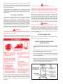
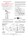
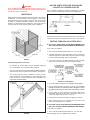
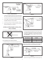
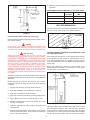
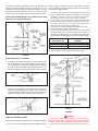
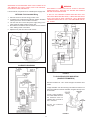
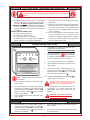
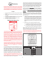
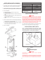
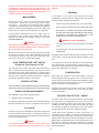
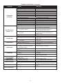
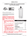
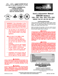
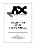
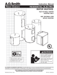
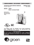
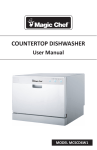
RESIDENTIAL
GAS WATER HEATER
OWNER'S MANUAL
GPDH/GPDT/GPDX
GAS MODELS
Thank you for buying this energy efficient water heater from
A.O. Smith Water Products Company. We appreciate your
confidence in our products.
with
Hot Surface Ignition
You should thoroughly read this manual before installation and/
or operation of this water heater. Please pay particular attention
to the important safety and operating instructions as well as the
WARNINGS and CAUTIONS.
TABLE OF CONTENTS
PAGE
GET TO KNOW YOUR WATER HEATER ...................... 2
GENERAL SAFETY INFORMATION ............................. 3
INSTALLATION ....................................................... 3-11
LIGHTING AND OPERATING LABEL ......................... 12
OPERATION .......................................................... 13-14
MAINTENANCE AND
TROUBLESHOOTING ........................................... 14-18
WARRANTY ................................................................ 19
CAUTION
TEXT PRINTED OR OUTLINED IN RED CONTAINS
INFORMATION RELATIVE TO YOUR SAFETY. PLEASE READ
THOROUGHLY BEFORE INSTALLING AND USING THIS
APPLIANCE.
A DIVISION OF A.O. SMITH CORPORATION
www.aosmithwaterheaters.com
KEEP THIS MANUAL IN THE POCKET ON HEATER FOR FUTURE REFERENCE
WHENEVER MAINTENANCE ADJUSTMENT OR SERVICE IS REQUIRED.
PART NO. 184707-001
PRINTED IN U.S.A. 0805
1
GET TO KNOW YOUR WATER HEATER
A
B
C
D
E
F
G
REPLACEMENT PARTS AND DELIMING PRODUCTS
Replacement parts and recommended delimer may be
ordered through authorized servicers or distributors. Refer to
the Yellow Pages for where to call or contact the A.O. Smith
Water Products Company, 125 Southeast Parkway, Franklin,
TN 37068, 1-800-433-2545. When ordering parts, provide
complete model and serial numbers (see rating plate), quantity
and name or part desired (as listed in Figure 1). Standard
hardware items may be purchased locally.
H
J
K
VENT PIPE-EXHAUST
ANODE
HOT WATER OUTLET
OUTLET (115 V. AC)
FLUE BAFFLE
GAS SUPPLY
MAIN MANUAL GAS
SHUT OFF VALVE
GROUND JOINT UNION
DIRT LEG
OUTER DOOR
L
M
N
O
P
Q
R
S
T
U
V
W
X
Y
Z
AA
BB
CC
UNION
INLET WATER SHUT
OFF VALVE
COLD WATER INLET
INLET DIP TUBE
TEMPERATURE AND
PRESSURE RELIEF VALVE
RATING PLATE
INSULATION
VENT TERMINAL EXHAUST
DRAIN VALVE
HSI ASSEMBLY
FLUE
DRAIN PAN
GAS VALVE
CONTROL HARNESS
INTAKE AIR PIPE
VENT TERMINAL INTAKE
INNER DOOR
BURNER ASSEMBLY
TEMPERATURE INDICATORS
X
TEMPERATURE ADJUSTMENT BUTTONS
TYPICAL NATURAL GAS PILOT
& MAIN BURNER
U
CC
HOT SURFACE
IGNITION ASSEMBLY
U
CERTAIN MODELS ARE EQUIPPED
WITH SIDE PLUMBING
CONNECTIONS FOR SPACE
HEATING. HOT AND COLD FITTING
ASSEMBLIES PART NO. 900126-2.
* CAUTION: 115VAC IN CONTROL
HARNESS AND INSIDE JACKET
GAS MODEL
GPDH/GPDT/GPDX
WITH HOT SURFACE IGNITION
FIGURE 1.
2
WARNING
Should you choose to apply an insulation blanket to this heater,
you should follow these instructions, see Figure 1 for identification
of components mentioned below. Failure to follow these
instructions can restrict the air flow required for proper
combustion, potentially resulting in fire, asphyxiation, serious
personal injury or death.
GENERAL SAFETY INFORMATION
EXTERNAL DAMAGE
Do not operate the water heater until it has been fully checked
out by a qualified technician, if the water heater:
• Has been exposed to fire or damage.
• Displays evidence of sooting.
•
Do not cover the outer door, thermostat or temperature
& pressure relief valve.
•
Do not cover the instruction manual. Keep it on the side of
the water heater or nearby for future reference.
•
Do obtain new warning and instruction labels from A.O. Smith
for placement on the blanket directly over the existing labels.
• Produces steam or unusually hot water.
If the water heater has been flooded it must be replaced.
CHEMICAL VAPOR CORROSION
LIQUID PETROLEUM MODELS
WARNING
CORROSION OF THE FLUEWAYS AND VENT SYSTEM MAY
OCCUR IF AIR FOR COMBUSTION CONTAINS CERTAIN
CHEMICAL VAPORS WHICH WILL BREAK DOWN INTO ACIDS
AT HIGH TEMPERATURE. SUCH CORROSION MAY RESULT
IN FAILURE AND RISK OF ASPHYXIATION.
WARNING
Water heaters for propane or liquefied petroleum gas (LPG) are
different from natural gas models. A natural gas heater will not
function safely on LP gas and no attempt should be made to
convert a heater from natural gas to LP gas.
LP gas must be used with great caution. It is highly explosive
and heavier than air. It collects first in the low areas making its
odor difficult to detect at nose level. If LP gas is present or even
suspected, do not attempt to find the cause yourself. Go to a
neighbor’s house, leaving your doors open to ventilate the house,
then call your gas supplier or service agent. Keep area clear
until a service call has been made.
Spray can propellants, cleaning solvents, refrigerator and air
conditioning refrigerants, swimming pool chemicals, calcium and
sodium chloride (water softener salt), waxes, and process
chemicals are typical compounds which are potentially corrosive.
Do not store products of this sort near the heater. Also, air which
is brought in contact with the heater should not contain any of
these chemicals. If necessary, uncontaminated air should be
obtained from remote or outside sources. The limited warranty
is voided when failure of water heater is due to a corrosive
atmosphere. (Refer to the limited warranty for complete terms
and conditions).
At times you may not be able to smell an LP gas leak. One
cause is odor fade, which is a loss of the chemical odorant that
gives LP gas its distinctive smell. Another cause can be your
physical condition, such as having a cold or a diminishing sense
of smell with age. For these reasons, the use of a propane gas
detector is recommended.
EXTENDED NON-USE PERIODS
IF YOU EXPERIENCE AN OUT-OF-GAS SITUATION, DO NOT
TRY TO RELIGHT APPLIANCES YOURSELF. Ask your
LP delivery person to relight pilots for you. Only trained LP
professionals should conduct the required safety checks in
accordance with industry standards.
WARNING
HYDROGEN GAS CAN BE PRODUCED IN A HOT WATER
SYSTEM SERVED BY THIS HEATER THAT HAS NOT BEEN
USED FOR A LONG PERIOD OF TIME (GENERALLY TWO
WEEKS OR MORE). HYDROGEN GAS IS EXTREMELY
FLAMMABLE. To reduce the risk of injury under these conditions,
it is recommended that the hot water faucet be opened for several
minutes at the kitchen sink before using any electrical appliance
connected to the hot water system. If hydrogen is present, there
will probably be an unusual sound such as air escaping through
the pipe as the water begins to flow. THERE SHOULD BE NO
SMOKING OR OPEN FLAME NEAR THE FAUCET AT THE TIME
IT IS OPEN.
INSTALLATION
REQUIRED ABILITY
INSTALLATION OR SERVICE OF THIS WATER HEATER
REQUIRES ABILITY EQUIVALENT TO THAT OF A LICENSED
TRADESMAN IN THE FIELD INVOLVED. PLUMBING, AIR
SUPPLY, VENTING AND GAS SUPPLY ARE REQUIRED.
INSULATION BLANKETS
Insulation blankets available to the general public for external
use on gas water heaters are not necessary with A.O. Smith
products. The purpose of an insulation blanket is to reduce the
standby heat loss encountered with storage tank water heaters.
Your A. O. Smith water heater meets or exceeds the National
Appliance Energy Conservation Act standards with respect to
insulation and standby loss requirements, making an insulation
blanket unnecessary.
GENERAL
The installation must conform to these instructions and the local
code authority having jurisdiction. In the absence of local codes,
the installation must comply with the current editions of the
National Fuel Gas Code, ANSI Z223.1/NFPA 54 and the National
Electrical Code, NFPA 70. The former is available from the
3
Canadian Standards Association, 8501 East Pleasant Valley
Road, Cleveland, OH 44131, and both documents are available
from the National Fire Protection Association, 1 Batterymarch
Park, Quincy, MA 02269.
CAUTION
In cold climates provide protection against freeze-up.
THE HEATER SHOULD BE LOCATED IN AN AREA WHERE
LEAKAGE OF THE TANK OR CONNECTIONS WILL NOT
RESULT IN DAMAGE TO THE AREA ADJACENT TO THE
HEATER OR TO LOWER FLOORS OF THE STRUCTURE.
The appliance, when installed, must be electrically grounded
in accordance with local codes or in the absence of local
codes with the current edition of the National Electrical Code,
ANSI/NFPA 70.
When such locations cannot be avoided, a suitable drain
pan should be installed under the heater, see Figure 1. The
pan should have a minimum length and width of at least
2 inches (51mm) greater than the diameter of the heater and
should be piped to an adequate drain. Drain pans suitable for
these heaters are available from your dealer or A. O. Smith Water
Products Company, 5621 W. 115th Street, Alsip, Illinois 60803.
LOCATION OF HEATER
The heater is design certified by the Canadian Standards
Association for installation with the following minimum clearances
between the water heater and combustible and noncombustible construction are: 0 inches from side, 0 inches
from back, 6 inches (152 mm) from front of jacket to closet door
and 12 inches (30.5 cm) from top of jacket to combustible and
non-combustible material. Minimum vent clearance: 0 inches.
Provide 24 inches (61 cm) front clearance for servicing and
adequate clearance between the jacket top and ceiling for servicing
the flue area. Also see clearance for venting on pages 6 & 7.
WARNING
DO NOT INSTALL THIS WATER HEATER DIRECTLY ON A
CARPETED FLOOR. A FIRE HAZARD MAY RESULT. Instead
the water heater must be placed on a metal or wood panel
extending beyond the full width and depth by at least 3 inches
(76.2mm) in any direction. If the heater is installed in a carpeted
alcove or closet, the entire floor shall be covered by the panel.
Also, see DRAINING.
WARNING
FAILURE TO HAVE REQUIRED CLEARANCES BETWEEN
WATER HEATER AND COMBUSTIBLE MATERIAL WILL
RESULT IN A FIRE HAZARD.
WATER CONNECTIONS
Adequate clearance for servicing this appliance should be
considered before installation, such as changing the anodes, etc.
Refer to Figure 1 for typical installation. A suitable pipe thread
sealant must be used to prevent leakage.
WATER (POTABLE) HEATING AND
SPACE HEATING
Installation:
Do not install water heater
where flammable products will
be stored or used unless the
main burner and pilot flames are
1.
All piping components connected to this unit for space
heating applications shall be suitable for use with potable
water.
2.
Toxic chemicals, such as those used for boiler treatment,
shall NEVER be introduced into this system.
3.
This unit may NEVER be connected to any existing heating
system or component(s) previously used with a non-potable
water heating appliance.
4.
When the system requires water for space heating at
temperatures higher than required for domestic water
purposes, a tempering valve must be installed. Please refer
to Figure 2 for suggested piping arrangement.
at least 18" above the floor. This
will reduce, but not eliminate, the
risk of vapors being ignited by the
main burner or pilot flame.
When installing the heater, consideration must be given to proper
location. Location selected should be as close to the wall as
practicable and as centralized with the water piping system as
possible.
FIGURE 2.
4
CLOSED WATER SYSTEM
A closed system will exist if a back-flow preventer (check valve),
pressure reducing valve, or other similar device is installed in
the cold water line between the water heater and the street main
(or well). Excessive pressure may develop due to the thermal
expansion of heated water causing premature tank failure or
intermittent relief valve operation. This type of failure is not covered
by the limited warranty. An expansion tank may be necessary in
the cold water supply to alleviate this situation, see Figure 1.
Contact the local plumbing authority.
BEFORE PLACING THE HEATER IN OPERATION, CHECK
FOR GAS LEAKAGE. USE SOAP AND WATER SOLUTION OR
OTHER MATERIAL ACCEPTABLE FOR THIS PURPOSE. DO NOT
USE MATCHES, CANDLES, FLAME OR OTHER SOURCES OF
IGNITION TO LOCATE GAS LEAKS.
RELIEF VALVE (P)- See FIGURE 1.
If the temperature and pressure relief valve on the appliance
discharges periodically, this may be due to thermal expansion
in a closed water supply system. Contact the water supplier or
local plumbing inspector on how to correct the situation. Do not
plug the temperature and pressure relief valve.
A NEW TEMPERATURE AND PRESSURE RELIEF VALVE
COMPLYING WITH THE STANDARD FOR RELIEF VALVES AND
AUTOMATIC GAS SHUT OFF DEVICES FOR HOT WATER
SUPPLY SYSTEMS, ANSI Z21.22 (CURRENT EDITION) MUST
BE INSTALLED IN THE HEATER IN THE MARKED OPENING
PROVIDED. THE VALVE MUST BE OF A SIZE (INPUT RATING)
THAT WILL BE ADEQUATE FOR YOUR SIZE HEATER.
GAS CONNECTIONS
The minimum gas supply pressure for input adjustment is
5.0" W.C. (1.25 kPa) for natural gas 11.0" W.C. (2.74 kPa) for propane.
Check the metal tag on the relief valve and compare it to the
heater’s rating plate. The pressure rating of the relief valve must
not exceed the working pressure shown on the rating plate of the
heater. In addition, the hourly Btu rated temperature steam
discharge capacity of the relief valve shall not be less than the
input rating of the heater. NO VALVE IS TO BE PLACED BETWEEN
THE RELIEF VALVE AND TANK. DO NOT PLUG THE RELIEF VALVE.
THE HEATER IS NOT INTENDED FOR OPERATION AT HIGHER
THAN 10.5" (2.6 kPa) FOR NATURAL & 13.0" (3.24 kPa) FOR
PROPANE WATER COLUMN SUPPLY PRESSURE. EXPOSURE
TO HIGHER GAS SUPPLY PRESSURE MAY CAUSE DAMAGE TO
THE CONTROL WHICH COULD RESULT IN FIRE OR EXPLOSION.
If overpressure has occurred such as through improper testing of gas
lines or emergency malfunction of the supply system, the control must
be checked for safe operation. Make sure that the outside vents on the
supply regulators and the safety vent valves are protected against
blockage. These are parts of the gas supply system not the
heater. Vent blockage may occur during ice storms.
The drain line connected to this valve must not contain a reducing
coupling or other restriction and must terminate near a suitable
drain to prevent water damage during valve operation. The
discharge line shall be installed in a manner to allow complete
drainage of both the valve and line. DO NOT THREAD, PLUG OR
CAP THE END OF THE DRAIN LINE.
IT IS IMPORTANT TO GUARD AGAINST CONTROL FOULING
FROM CONTAMINANTS IN THE GAS WAYS. SUCH FOULING
MAY CAUSE IMPROPER OPERATION, FIRE OR EXPLOSION.
VENTING
WARNING
NEVER OPERATE THE HEATER UNLESS THE INTAKE AND
EXHAUSTARE VENTED TO THE OUTDOORS AND HAS ADEQUATE
AIR SUPPLY TO AVOID RISKS OF IMPROPER OPERATION, FIRE,
EXPLOSION, OR ASPHYXIATION. IF THE WATER HEATER IS BEING
INSTALLED AS A REPLACEMENT FOR AN EXISTING POWER
VENTED HEATER IN PRE-EXISTING VENTING, A THOROUGH
INSPECTION OF THE EXISTING VENTING SYSTEM MUST BE
PERFORMED PRIOR TO ANY INSTALLATION WORK. VERIFY THAT
THE CORRECT MATERIAL AS DETAILED ABOVE HAS BEEN USED,
AND THAT THE MINIMUM OR MAXIMUM VENT LENGTHS AND
TERMINAL LOCATION AS DETAILED IN THIS MANUAL HAVE BEEN
MET. CAREFULLY INSPECT THE ENTIRE VENTING SYSTEM FOR
ANY SIGNS OF CRACKS OR FRACTURES, PARTICULARLY AT THE
JOINTS BETWEEN ELBOWS AND OTHER FITTINGS AND THE
STRAIGHT RUNS OF VENT PIPE. CHECK THE SYSTEM FOR SIGNS
OF SAGGING OR OTHER STRESSES IN THE JOINTS AS A RESULT
OF MISALIGNMENT OF ANY COMPONENTS IN THE SYSTEM. IF ANY
OF THESE CONDITIONS ARE FOUND, THEY MUST BE
CORRECTED IN ACCORDANCE WITH THE VENTING
INSTRUCTIONS IN THIS MANUAL BEFORE COMPLETING THE
INSTALLATIONAND PUTTING THE WATER HEATER INTO SERVICE.
All piping must comply with local codes and ordinances or with
the National Fuel Gas Code (ANSI Z223.1, NFPA 54) whichever
applies. Copper and brass tubing and fittings (except tin lined
copper tubing) shall not be used.
REFER TO FIGURE 1 FOR CONNECTION DETAILS. BEFORE
ATTACHING THE GAS LINE BE SURE THAT ALL GAS PIPE IS
CLEAN ON THE INSIDE.
TO TRAP ANY DIRT OR FOREIGN MATERIAL IN THE GAS SUPPLY
LINE, A DIRT LEG (SOMETIMES CALLED DRIP LEG) MUST BE
INCORPORATED IN THE PIPING, SEE FIGURE 1. The dirt leg must
be readily accessible. Install in accordance with recommendations of
serving gas supplier. Refer to the current edition of ANSI Z223.1.
To prevent damage, care must be taken not to apply too much
torque when attaching gas supply pipe to gas valve inlet. The
valve inlet has a hexagon shape for use with a backup wrench.
Apply joint compounds (pipe dope) sparingly and only to the
male threads of pipe joints. Do not apply compound to the first
two threads. Use compounds resistant to the action of liquefied
petroleum gases. Do not use teflon tape on gas valve.
WARNING
THESE MODELS ARE CERTIFIED FOR VERTICAL VENTING
AND SIDE WALL VENTING. THE UNIT CONSISTS OF AN INTAKE
VENT TERMINAL AND AN EXHAUST VENT TERMINAL WHICH
MUST BE USED TO TERMINATE THE VENTING ARRANGEMENT.
IF THE VENT TERMINALS SUPPLIED WITH THIS UNIT ARE
NOT USED TO TERMINATE THE VENTING ARRANGEMENT,
THE RISK OF IMPROPER OPERATION, FIRE, EXPLOSION, OR
ASPHYXIATION WILL INCREASE.
DISCONNECT THE APPLIANCE AND ITS INDIVIDUAL SHUT OFF
VALVE FROM THE GAS SUPPLY PIPING SYSTEM DURING ANY
SUPPLY PRESSURE TESTING EXCEEDING 1/2 PSI
(3.5 kPa). GAS SUPPLY LINE MUST BE CAPPED WHEN
DISCONNECTED FROM THE HEATER. FOR TEST PRESSURES AT
1/2 PSI (3.5 kPa) OR LESS, THE APPLIANCE NEED NOT BE
DISCONNECTED, BUT MUST BE ISOLATED FROM THE SUPPLY
PRESSURE TEST BY CLOSING THE MAIN MANUAL GAS VALVE.
5
COMBUSTION AIR AND EXHAUST
•
The Power Direct Vent outlet terminal of over 50,000 BtuH
input models shall terminate at least 12" (30.5 cm) below,
12" (30.5 cm) horizontally from or 12" (30.5 cm) above any door,
window or gravity air inlet into the building, see Figure 4.
•
18" (45.7 cm) minimum from other natural draft (gravity)
direct vent, power vent or power direct vent appliance inlet
and/or outlet vent(s) when directly above or 135° to either
side of center line, see Figure 5.
•
24" (61 cm) minimum from any appliance inlet and/or outlet
vents when directly below or 45° to either side of center
line, see Figure 5.
WARNING
WHEN DETERMINING THE INSTALLATION LOCATION
FOR A POWER DIRECT VENT WATER HEATER, SNOW
ACCUMULATION AND DRIFTING SHOULD BE CONSIDERED
IN AREAS WHERE APPLICABLE.
Venting Through an Outside Wall - Clearances
•
0" clearance for 3" PVC, ABS, or CPVC Schedule 40 piping
from combustible surfaces.
•
18" (45.7 cm) minimum in all directions from any
obstruction, such as a wall, that may interfere.
•
12" (30.5 cm) minimum from the ground and corners, 9"
(23 cm) ceiling overhang, see Figure 3.
FIGURE 5.
•
The location selection must provide clearances for servicing
and proper operation of the water, see Figure 6.
•
The venting system must be installed in a manner which
allows inspection of the installation of the venting pipes
and joints as well as periodic inspection after installation
as required by the National Fuel Gas Code ANSI Z223.1.
FIGURE 3.
•
The Power Direct Vent outlet terminal shall terminate at
least 36" (91 cm) above any forced air inlet located within
10 feet (305 cm), see Figure 4.
•
The Power Direct Vent outlet terminal of 50,000 BtuH input
models or less shall terminate at least 9" (23 cm) below,
9" (23 cm) horizontally from or 9" (23 cm) above any door,
window or gravity air inlet into the building, see Figure 4.
FIGURE 6.
FIGURE 4.
6
AIR FOR VENTILATION FOR APPLIANCES
LOCATED IN CONFINED SPACES
WARNING
VENT TERMINATION MUST NOT BE WITHIN 4 FEET (122 cm)
OF ANY ITEMS SUCH AS GAS METERS, GAS VALVES OR OTHER
GAS REGULATING EQUIPMENT.
Air for ventilation should be provided if installed in a confined
space. Refer to the National Fuel Gas Code, ANSI Z223.1.
WIRE FENCE
When the water heater outlet terminal is low enough to be touched
accidentally, or is accessible to small children, a wire mesh
chain link fence (as show in Figure 7) may be used. Care should
be taken to maintain adequate ventilation around the outlet
terminal. If a chain link fence is installed, it must not be used as
a storage area for items that may block proper ventilation.
FIGURE 9.
Horizontal runs must be securely supported at 3 1/2 foot (8.9 cm)
intervals and vertical runs supported at 5 foot (1.5 cm) intervals.
VENTING THROUGH AN OUTSIDE WALL
A. ALL 75 GAL. (283.9L) 65,000 & 70,000 BTU/HR MODELS & 50
GAL. (189.3L) 60,000 & 65,000 BTU/HR MODELS, SEE FIGURE 10.
In the carton is supplied:
1. Two 3" inlet and outlet PVC Schedule 40 - 45° vent caps.
2. A 3" ABS Schedule 40 - 90° street elbow; used to connect the
outlet vent pipe to the water heater when the outlet vent pipe
is to be turned horizontally directly off the blower.
FIGURE 7.
3. A 5' (1.52 m) section of 3" ABS Schedule 40 outlet vent pipe
(more may be required and must be supplied locally).
Venting Through Roof - Clearances
•
0" clearance for 3" PVC, ABS, or CPVC Schedule 40 piping
from combustible and noncombustible surfaces.
•
The vent exhaust outlet and air inlet terminals shall terminate at
least 18 inches (45.7 cm) above the roof surface, see Figure 8.
•
The venting system must be installed in a manner which
allows inspection of the installation of the venting pipes and
joints as well as periodic inspection after installation as
required by ANSI Standards.
FIGURE 10. HI BTU MODELS.
1. The water heater requires its own (separate) venting system.
2. Only 3" ABS Schedule 40 piping & fittings are acceptable
materials on the first 5' of outlet vent system. This applies to only 50
gal. (189.3 L) Hi BTU input models and all 75 gal. (283.9 L) models.
3. 3" PVC, ABS, or CPVC Schedule 40 piping & fittings are
acceptable materials for the inlet vent system and for the
outlet vent system after the first 5' (1.52 m).
4. It cannot be connected to existing vent piping or chimney.
5. When venting through an outside wall, the vents must
terminate horizontally to the outdoors.
B. ALL 50 GAL. (189.3 L) 38,000 AND 40,000 BTU/HR MODELS & 40
GAL. (151.4 L) 36,000 & 40,000 BTU/HR MODELS, SEE FIGURE 11.
In the carton is supplied:
1. Two 3" inlet and outlet PVC Schedule 40 - 45° vent caps.
All other piping must be supplied by the supplier.
FIGURE 8.
7
FIGURE 11. STANDARD MODELS.
FIGURE 14.
*
If making an immediate horizontal run of vent off the blower,
two 3" PVC or ABS Schedule 40 street elbows are required.
1.
The water heater requires its own (separate) venting system.
2.
3" PVC, ABS or CPVC Schedule 40 piping and fittings are
acceptable materials for the vent system.
3.
It cannot be connected to existing vent piping or chimney.
4.
When venting through an outside wall, the vents must
terminate horizontally to the outdoors.
VENTING SYSTEM EXAMPLE INSTALLATION
FOR ALL MODELS
FIGURE 15.
The vent piping cannot under any circumstances be run downhill.
2.
FIGURE 12.
The vent piping can be installed as follows:
The total vertical and horizontal vent runs cannot exceed
the maximum length with the number of 90° elbows as
specified in the table below. If more elbows are required,
the venting distance must be reduced 5 feet (1.52 m) for
every 90° elbows:
3" DIA. VENTS
MAX. LENGTH (FT.)
NUMBER OF 90° DEG.
ELBOWS *
45 (13.72 m)
1
40 (12.2 m)
2
35 (10.7 m)
3
1. Horizontal runs require a minimum 1/8" (3.2mm) rise per 5' (1.52 m).
*NOTE: Two 45° elbows are equivalent to one 90° elbow. One
90° elbow equals 5 feet (1.52 m) of equivalent vent length.
FIGURE 16.
3.
FIGURE 13.
8
Minimum vent length for all models is 18 inches (45.7 cm).
9. Remember that vent pipes must be adequately and securely
supported.
APPROXIMATE SETTING TIME FOR 2-1/2" to 4" PIPE JOINTS.
MOVEMENT
OF JOINT
COMPLETE
SET
90°F (32°C) TO 150°F (66°C)
3/4 hr.
8 hrs.
50°F (10°C) TO 90°F (32°C)
1 hr.
15 hrs.
9°F (-12°C) TO 50°F (10°C)
1-1/3 hr.
18 hrs.
VENT PIPE SEPARATION
The inlet and outlet vent pipes must be separated by a minimum
distance of 6-1/2" (16.5 cm) up to 24" (61cm) maximum.
FIGURE 17.
Cementing PVC, ABS or CPVC Pipe and Fittings
Read and observe all safety information printed on printer, cleaner,
and cement container.
DANGER
Primer, cleaner, and cements are extremely flammable. They
are harmful or fatal if swallowed. The vapors are harmful. They
may irritate eyes and skin and can be absorbed through the skin.
FIGURE 18.
CUTTING OPENINGS THROUGH AN OUTSIDE WALL AND
COLLAR INSTALLATION
PRECAUTIONS
Always store primers, cleaner, and cements in cool, dry, well
ventilated places. Do not store these near heat, sparks, or flames.
Keep container closed. Use them in well ventilated areas. Wear
impervious clothing while handling. Do not smoke, eat, or drink
while handling. Wash thoroughly after handling and before eating.
Wear eye protection when handling. If swallowed, drink water,
do not induce vomiting, and call a physician or poison control
center immediately. If inhaled, get fresh air and seek medical
attention if ill feelings persist. In case of eye and skin contact,
immediately flush with plenty of water for 15 minutes and seek
medical attention if irritation persists. KEEP OUT OF REACH OF
CHILDREN.
After reading the manual and you have determined the location
of the opening in the wall, (using the drawing below), cut one
3-1/2" (89 cm) diameter hole for the inlet vent piping and one
3-1/2" (89 cm) diameter hole for the outlet vent piping through an
exterior wall.
NOTE: When determining locations of the openings in the
outside wall allow for the 1/8" (3.2 mm) rise per 5' (1.52 m) that
has taken place in the horizontal run.
All primers, cleaners and cements must meet all local codes and
applicable standard of the American Society For Testing Materials
Standards.
Before using primers, cleaners, and cements, stir or shake,
making sure contents are liquid. Do not use if found to be lumpy
or jelly-like.
1. Cut pipe ends squarely, removing all burrs and dirt.
2. Dry fit pipe and fittings to be connected for proper fit.
3. Clean pipe and fitting with a primer/cleaner.
4. Apply a thin coat of cement to fitting, avoiding puddling inside.
5. Apply a liberal coat of cement to pipe, leaving no voids.
6. QUICKLY assemble parts while cement is fluid! If you wait
too long, re-coat pipes.
FIGURE 19.
7. Push pipe completely into socket of fitting, turning as it goes
until it bottoms.
The 3" PVC, ABS or CPVC Schedule 40 vent pipe can be run from
the water heater through the wall or from the wall to the water
heater, whichever is most convenient. The vent pipe must extend
a minimum of 1-1/2" (38 mm) through the exterior wall. Extending
the vent cap as far as possible from the surface of the exterior
8. Hold pipe and fitting together for 30 seconds. Then carefully
clean off excess with a cloth. Allow connections a sufficient
time to cure before disturbing.
9
(50 Gal. (189.3 L) Hi BTU input & all 75 Gal. (283.9 L) Models
only) is supplied on certain models only. (More may be required
and must be supplied locally).
wall will help minimize discoloration of the wall. Note that the
inside flue mounting adaptors must be slipped over the vent
piping before locating the pipe through the wall. Before securing
the inside and outside collars to the wall, use a silicone sealer
between pipe and opening to insure a water and air tight seal.
1. The water heater requires its own (separate) venting system.
2. Only 3" ABS Schedule 40 piping and fittings are acceptable
materials on the first 5' (1.52 m) of the outlet vent system for
some 50 Gal. (189.3 L) and 75 Gal. (283.9 L) models.
3. 3" PVC, ABS, or CPVC Schedule 40 piping and fittings are
acceptable materials for the inlet vent system and for the outlet
vent system (after the first 5' (1.52 m) for 50 Gal. (189.3 L) Hi
BTU input and 75 Gal. (283.9 L) Models only).
4. It cannot be connected to existing vent piping or chimney.
5. It must terminate vertically to the outdoors.
6. The total vertical and horizontal runs cannot exceed the
maximum length with a maximum number of 90° elbows as
specified in the table below. If more elbows are required, the
venting distance must be reduced 5' (1.52 m) for every 90° elbow.
INSTALLATION SHOWING USE OF PVC, ABS OR CPVC PIPE
FOR INLET AND OUTLET VENT PIPE.
3" DIA. VENTS
MAX. LENGTH (FT.)
45 (13.72 m)
40 (12.2 m)
35 (10.7 m)
NUMBER OF 90° DEG.
ELBOWS*
1
2
3
*NOTE: Two 45° elbows are equivalent to one 90° elbow. One
90° elbow equals 5 ' (1.52 m) of equivalent vent length.
FIGURE 20.
CONNECTING VENT TO BLOWER
1. If making an immediate horizontal run of vent off the blower,
one 3" PVC inlet and one 3" PVC (ABS for 50 Gal. (189.3 L)
and 75 Gal.(283.9 L) Models) outlet Schedule 40 street elbows
are required. Place the elbow in the required direction on the
blower and using three sheet metal screws, attach the elbow.
FIGURE 21.
2. If there is to be a vertical run from the blower, the 3" PVC inlet
and the 3" PVC (ABS for 50 Gal. (189.3 L) and 75 Gal.(283.9
L) Models) outlet Schedule 40 pipe must be attached to the
blower and venting hood, using six sheet metal screws.
FIGURE 23.
WIRING
FIGURE 22.
DANGER
DO NOT USE AN EXTENSION CORD. IF THERE IS NOT A
SUITABLE RECEPTACLE AND/OR LOCAL CODES PROHIBIT
USE OF A POWER CORD, FIELD WIRING MUST BE PROVIDED.
THE APPLIANCE, WHEN INSTALLED, MUST BE ELECTRICALLY
VENTING THROUGH A ROOF
Two 3" inlet and outlet PVC Schedule 40-45° vent caps are supplied.
A 5' (1.52 m) section of 3" ABS Schedule 40 outlet vent pipe
10
GROUNDED IN ACCORDANCE WITH LOCAL CODES OR IN
THE ABSENCE OF LOCAL CODES, WITH THE NATIONAL
ELECTRICAL CODE, ANSI/NFPA 70.
WARNING
DISCONNECT FROM ELECTRICAL SUPPLY BEFORE
SERVICING UNIT. REPLACE ALL DOORS AND PANELS
BEFORE OPERATING HEATER.
If local codes do not permit use of a flexible power supply cord.
IF ANY OF THE ORIGINAL WIRES SUPPLIED WITH THE
APPLIANCE MUST BE REPLACED, IT MUST BE REPLACED
WITH APPLIANCE WIRE MATERIAL WITH MINIMUM
TEMPERATURE RATING OF 105°C AND A MINIMUM SIZE OF
NO. 18 AWG.
OPTIONAL Field Installed Wiring
1. Remove screws to remove wiring junction cover.
2. A standard 1/2" conduit opening has been made in the water
heater junction box for the conduit connection.
3. Use wire nuts and connect the power supply wiring to the
wires inside the water heater's junction box.
4. Be certain that neutral and line connections are not reversed
when making these connections.
5. Replace front plate and secure with screws.
FIGURE 24.
SCHEMATIC DIAGRAMS
FIGURE 26.
T & P VALVE AND PIPE INSULATION
(ON SELECTED MODELS)
Remove insulation for T & P valve and pipe connections from
carton.
Fit pipe insulation over the incoming cold water line and the hot
water line. Make sure that the insulation is against the top cover
of the heater.
Fit T & P valve insulation
over valve. Make sure that
the insulation does not
interfere with the level of
the T & P valve.
S e c u r e a l l i n su la tion
using tape.
FIGURE 25.
FIGURE 27.
11
FOR YOUR SAFETY READ BEFORE OPERATING
WARNING: If you do not follow these instructions exactly, a fire or
explosion may result causing property damage, personal injury or loss
of life.
BEFORE OPERATING: ENTIRE SYSTEM MUST BE FILLED WITH WATER AND AIR PURGED FROM ALL LINES.
A. This appliance does not have a pilot. It is equipped
with an ignition device which automatically lights
the burner. Do NOT try to light the pilot by hand.
B. BEFORE OPERATING smell all around the appliance
area for gas. Be sure to smell next to the floor
because some gas is heavier than air and will settle
on the floor.
WHAT TO DO IF YOU SMELL GAS:
• Do not try to light any appliance.
• Do not touch any electric switch;
do not use any phone in your building.
• Immediately call your gas supplier from a neighbor’s
phone. Follow the gas supplier’s instructions.
•
If you cannot reach your gas supplier, call the fire
department.
C. Use only your hand to push in the gas control buttons.
Never use tools. If the control buttons will not push
in, don’t try to repair them, call a qualified service
technician. Force or attempted repair may result in
a fire or explosion.
D. Do not use this appliance if any part has been under
water. Immediately call a qualified service
technician to inspect the appliance and to replace
any part of the control system and any gas control
which has been under water.
OPERATING INSTRUCTIONS
1.
This appliance is equipped with a device which
automatically lights the burner.
DO NOT TRY TO LIGHT THE BURNER BY HAND.
6.
Wait five (5) minutes to
clear out any gas.
If you then smell gas,
STOP! Follow “B”
in the safety information above on this label. If
you don’t smell gas, go to the next step.
7.
Turn on all electrical power to the appliance.
8.
Set the ON/OFF switch on the control box to the
“ON” position.
9.
Set the thermostat to desired setting by first
and HOTTER
pressing the COOLER
buttons together and holding for 1 second.
Then press the HOTTER button
.
10. WATER TEMPERATURE ADJUSTMENT
approximately 120°F (49°C).
STOP! Read the safety information above,
on this label.
2.
Set the ON/OFF switch on the control box to the
“ON” position.
3.
Set the thermostat to the lowest setting by first
and HOTTER
pressing the COOLER
buttons together and holding for 1 second. Then
press the COOLER button
until the WARM
indicator light appears.
Set the ON/OFF switch on the control box to the
“OFF” position.
4.
5.
is
CAUTION: Hotter water increases the risk
of scald injury. Consult the instruction
manual before changing temperature.
11. If the appliance will not operate, follow the
instructions “TO TURN OFF GAS TO
APPLIANCE” and call your technician or gas
supplier.
WARNING: TURN OFF ALL ELECTRIC
POWER BEFORE SERVICING
TO TURN OFF GAS TO APPLIANCE
1.
Set thermostat to the lowest setting by first
and HOTTER
pressing the COOLER
buttons together and holding for 1 second. Then
press the COOLER button
until the WARM
indicator light appears.
12
2.
Set the ON/OFF switch on the control box to the
“OFF” position.
3.
Turn off all electric power to the appliance if service
is to be performed.
Figure 28 shows the approximate water temperatures produced
at various thermostat dial settings. Short repeated heating cycles
caused by small hot water uses can cause temperatures at
the point of use to exceed the thermostat setting by up to 30°F
(-1°C). If you experience this type of use you should consider
using lower temperature settings to reduce scald hazards.
OPERATION
NEVER OPERATE THE HEATER WITHOUT FIRST BEING
CERTAIN IT IS FILLED WITH WATER AND A TEMPERATURE
AND PRESSURE RELIEF VALVE IS INSTALLED IN THE RELIEF
VALVE OPENING OF THE HEATER. DO NOT ATTEMPT TO
OPERATE HEATER WITH COLD WATER INLET VALVE CLOSED.
Valves for reducing the point of use temperature by mixing cold
and hot water are available, see Figure 2. Also available are
inexpensive devices that attach to faucets to limit hot water
temperatures. Contact a licensed plumber or the local plumbing
authority.
FILLING
1.
2.
3.
4.
5.
To avoid any unintentional changes in water temperature
settings, the control has a tamper resistant feature for changing
the temperature setting. To change the temperature setting follow
these instructions:
Close the heater drain valve by turning handle clockwise,
Figure 1.
Open a nearby hot water faucet to permit the air in the system
to escape.
Fully open the cold water inlet pipe valve allowing the heater
and piping to be filled, see Figure 1.
Close the hot water faucet as water starts to flow.
The heater is ready to be operated.
1.
"Wake Up" the temperature indicators by holding down both
"COOLER" and "HOTTER" temperature adjustment buttons
at the same time for one second, see Figure 28. One or two
of the temperature indicators will light up. These indicators
will only remain on for 30 seconds if no further buttons are
pressed. After 30 seconds the control will go back to "Sleep"
mode.
2.
Release both of the temperature adjustment buttons.
TEMPERATURE REGULATION
A. To decrease the temperature press and release the
"COOLER" button until the desired setting is reached.
B. To increase the temperature press and release the
"HOTTER" button until the desired setting is reached.
NOTE: Holding down the button will not continue to lower or
raise the temperature setting. The button must be pressed and
released for each temperature change desired.
DANGER
THIS WATER HEATER IS EQUIPPED WITH AN ADJUSTABLE
THERMOSTAT TO CONTROL WATER TEMPERATURE. HOT
WATER TEMPERATURES REQUIRED FOR AUTOMATIC
DISHWASHER AND LAUNDRY USE CAN CAUSE PAINFUL
SCALDING WITH POSSIBLE SERIOUS AND PERMANENT
INJURY. THE TEMPERATURE AT WHICH INJURY OCCURS
VARIES WITH THE PERSON’S AGE AND THE TIME OF THE
EXPOSURE. THE SLOWER RESPONSE TIME OF CHILDREN,
AGED OR DISABLED PERSONS INCREASES THE HAZARDS
TO THEM. NEVER ALLOW SMALL CHILDREN TO USE A HOT
WATER TAP, OR TO DRAW THEIR OWN BATH WATER. NEVER
LEAVE A CHILD OR DISABLED PERSON UNATTENDED IN A
BATHTUB OR SHOWER.
SHOULD OVERHEATING OCCUR OR THE GAS SUPPLY FAIL
TO SHUT OFF, TURN OFF THE MAIN MANUAL GAS SHUTOFF
VALVE TO THE APPLIANCE, SEE FIGURE 1(G).
THE WATER HEATER SHOULD BE LOCATED IN AN AREA
WHERE THE GENERAL PUBLIC DOES NOT HAVE ACCESS. IF
A SUITABLE AREA IS NOT AVAILABLE, A COVER SHOULD BE
INSTALLED OVER THE THERMOSTAT TO PREVENT
TAMPERING.
It is recommended that lower water temperatures be used to
avoid the risk of scalding. It is further recommended, in all cases,
that the water temperature be set for the lowest temperature
which satisfies your hot water needs. This will also provide the
most energy efficient operation of the water heater. The water
temperature setting was factory set at the lowest temperature;
Pressing the "COOLER" button decreases temperature and
pressing the "HOTTER" button increases the temperature.
Time to Produce
Display
2nd & 3rd Degree
A B C Burns on Adult Skin
Temperature Setting
C=Flashing=approx. 160°F(71 oC)
C = Approx. 150°F(66oC)
About 1 1/2 seconds
B = Approx. 140°F(60oC)
Less than 5 seconds
o
A = Approx. 130°F(54 C)
SETTING THE WATER HEATER TEMPERATURE AT 120°F (49°C)
(APPROX. “ ” MARK ON TEMPERATURE SETTING OF GAS
VALVE) WILL REDUCE THE RISK OF SCALDS. Some states
require settings at specific lower temperatures.
About 30 seconds
= Approx. 120°F(49oC)
More than 5 minutes
WARM = Approx. 80°F(27oC)
--------------
FIGURE 28.
13
About 1/2 seconds
CONTROL SEQUENCE - HOT SURFACE DIRECT IGNITION
Pre-purge
5 seconds.
HSI Warm-up
20 seconds.
Ignition Activation Period
4 seconds.
Flame Recognition Period
1 second.
Ignition Trial
4 seconds.
Interpurge
5 seconds.
Post-purge
5 seconds.
Retries
2
Reset from Lockout
1 hr.
Flame Sensing (Nominal)
HSI Off/Run Mode
4.0µ DC
WATER HEATING IGNITION SEQUENCE
(Make sure gas and electric power are connected properly)
1. The ignition control module is powered and monitors the
system, waiting for a call for heat from the thermostat.
2. The thermostat calls for heat by reading a resistance value
within a given range directly proportional to water temperature.
3. The control Module:
a. Checks the pressure switch for an open circuit.
b. Energizes the blower.
c. Checks the pressure switch for a closed circuit to prove
draft.
d. Sends line voltage to the hot surface igniter with a
20 second warm up period.
e. Opens the gas valve and checks the sensing rod for
flame.
HIGH ALTITUDE INSTALLATION
WARNING
INSTALLATIONS ABOVE 2000 (610 m) FEET REQUIRE
REPLACEMENT OF THE BURNER ORIFICE IN ACCORDANCE
WITH THE NATIONAL FUEL GAS CODE (ANSIZ223.1/ NFPA 54).
FAILURE TO REPLACE THE ORIFICE WILL RESULT IN IMPROPER
AND INEFFICIENT OPERATION OF THE APPLIANCE, PRODUCING
CARBON MONOXIDE GAS IN EXCESS OF SAFE LIMITS, WHICH
COULD RESULT IN EXCESS OF SAFE LIMITS, WHICH COULD
RESULT IN SERIOUS PERSONAL INJURY OR DEATH.
4. The burner heats the water to the desired thermostat setting.
a. The resistance in the thermostat rises to the value
selected by the temperature setting.
b. The control module closes the gas valve and 5 seconds
later, removes power from the blower.
A.O. Smith builds models specifically for high altitude service.
Please check the rating plate before making changes.
5. Cycle is completed.
VENTING MANUAL RESET SWITCH
There is a venting manual reset switch located on the venting
hood. If the switch is activated, it will not reset itself. Before
resetting this reset switch, check for flue blockage and propriety
of the venting systems. To reset, press the red button.
FIGURE 30.
MAINTENANCE
WARNING
DISCONNECT FROM ELECTRICAL SUPPLY BEFORE
SERVICING UNIT.
FOR YOUR SAFETY, WATER HEATER SERVICE SHOULD BE
PERFORMED ONLY BY A QUALIFIED SERVICE TECHNICIAN.
READ THE GENERAL SAFETY INFORMATION SECTION FIRST.
FIGURE 29.
14
USERS OF THIS APPLIANCE SHOULD BE AWARE THAT GAS
COMPONENTS WEAR OUT OVER A PERIOD OF TIME. THE
GAS CARRYING COMPONENTS OF THIS APPLIANCE SHOULD
BE INSPECTED FOR PROPER OPERATION PERIODICALLY BY
A QUALIFIED SERVICE TECHNICIAN.
CONTACT AND DISCHARGE SAFELY TO PREVENT WATER
DAMAGE.
DRAINING
If the heater is to be shut off and exposed to freezing
temperatures, it must be drained. Water, if left in the tank and
allowed to freeze, will damage the heater.
MAIN BURNER
Check main burner every 12 months for proper flame
characteristics. This is done by removing door(s) on heater,
see Figure 1. The main burner should provide complete
combustion of gas; ignite rapidly; give reasonably quiet operation;
cause no excessive flame lifting from burner ports. Make sure
that the flow of combustion and ventilation air is not blocked.
•
Turn off the gas and cold water inlet valve to the heater.
•
Open a nearby hot water faucet and the heater drain valve.
•
BE CAREFUL TO GRASP THE DRAIN VALVE HANDLE
SO THAT THE HAND IS NOT EXPOSED TO HOT WATER.
IF DESIRED, A HOSE MAY BE CONNECTED TO THE
DRAIN VALVE TO CARRY THE WATER AWAY.
If proper flame characteristics are not evident, check for
accumulation of lint or other foreign material that restricts or
blocks the air openings in the heater or burner. Also check
AIR REQUIREMENTS.
DANGER: The water CAN BE HOT.
WARNING
SOOT BUILD-UP INDICATES A PROBLEM THAT REQUIRES
CORRECTION BEFORE FURTHER USE. CONSULT WITH A
QUALIFIED SERVICE TECHNICIAN.
Should the main burner or burner air openings require cleaning,
turn the blower switch to “OFF” position and allow the burner to
cool. Remove the burner and clean with a soft brush. Clean
main burner orifice with a suitable soft material.
The drain valve must be left open during the shutdown
period.
•
To restart heater, refer to the FILLING instructions under
OPERATION.
Periodically open the drain valve and allow the water to run until
it flows clean. This will help prevent sediment build-up in the
tank.
HIGH TEMPERATURE LIMIT SWITCH
(Single-Use Type Energy Cut Off)
It is normal for lime and scale deposits to form within the tank.
Such deposits will not be removed by periodic draining. It is
necessary to chemically delime the affected parts in water areas
where such deposits are encountered.
The thermostat has a built-in limit switch which will actuate in
case of excessive water temperatures. The heater cannot be
relit until the gas control valve is replaced. It is important that a
serviceman be called to determine the reason for limit operation
and thus avoid repeated thermostat replacement. Lower the
temperature adjustment setting on new control.
CONDENSATION
Water vapor can condense on the cooler surfaces of the tank
forming droplets, these drip into the fire or run out on the floor.
This is common at the time of startup after installation, during
periods of time when incoming water is very cold, or the heater
may be undersized for the requirements.
VENTING SYSTEM
HAVE VENTING SYSTEM CHECKED EVERY SIX MONTHS FOR
OBSTRUCTIONS AND/OR DETERIORATION IN VENT PIPING.
Droplets from the bottom of the flue may be due to corrosive
combustion products or improper vent. Check with your dealer
for more information.
POWER VENTER MAINTENANCE
The “POWER” venter must be inspected yearly.
1.
•
CATHODIC PROTECTION - ANODE
MOTOR - Motor must rotate freely.
The anode rod is used to protect the tank from corrosion. Most
hot water tanks are equipped with an anode rod. The submerged rod sacrifices itself to protect the tank. Instead of
corroding the tank, water ions attack and eat away the anode
rod. This does not affect the water’s taste or color. The rod must
be maintained to keep the tank in operating condition.
For safety and satisfactory operation it is recommended that the
heater be checked once a year by a competent service person.
T & P VALVE
At least once a year, the temperature and pressure relief valve
must be checked to ensure that it is in operating condition. Lift
the lever at the top of the valve several times until the valve seats
properly and operates freely.
Anode deterioration depends on water conductivity, not
necessarily water condition. A corroded or pitted anode rod
indicates high water conductivity and should be checked and/or
replaced more often than an anode rod that appears to be intact.
Replacement of a depleted anode rod can extend the life of your
water heater. Inspection should be conducted by a qualified
technician, and at a minimum should be checked annually after
the warranty period.
DANGER
THE WATER PASSING OUT OF THE VALVE DURING THIS
CHECKING OPERATION MAY BE EXTREMELY HOT. AVOID
15
•
A hydrogen sulfide (rotten egg) odor may result if water contains
high sulfate and/or minerals. Chlorinating the water supply
should minimize the problem, see EXTENDED NON-USE
PERIODS.
If after working with your dealer or service agent the problem
has not been resolved to your satisfaction, please let us
know by either writing to us at:
A.O. Smith Water Products Company
Service Department
106 Adkisson St.
Ashland City, TN 37015
NOTE: Anode rod must remain installed (except for inspection)
to avoid shortening tank life. See LIMITED WARRANTY. Replace
as necessary.
or, going to our website at: www.aosmithwaterheaters.com
SERVICE AND REPAIR
Please click on: "Mail"
then click on: "Service"
and leave us a message.
The A.O. Smith water heater requires no special care other than
the normal maintenance as noted above. If you are having a
problem with your water heater, before calling for service please
refer to the following TROUBLESHOOTING sections. If service
becomes necessary, contact your dealer, installer or an
authorized service agent. Do not attempt to repair the water heater
yourself. Any work performed by unauthorized personnel may
void the warranty.
Please be sure to provide the following information when writing
or e-mailing:
• Model Number
• Serial Number
If you are having a problem with your A.O. Smith water heater
and are not pleased with the service you received:
• Date of Original Purchase
•
• Explanation of Problem
• Date Problem Originated
First, please contact your dealer or the A.O. Smith authorized
service agent in your area and explain to them why you are
not satisfied. This will usually correct the problem.
Also, please be sure to include a daytime telephone number.
TROUBLE SHOOTING HELP
THERMOSTAT AND GAS SUPPLY CHECK
Is gas being supplied to the thermostat?
No
Yes
Yes
Turn "ON" gas supply.
Is thermostat calling for heat? Run (hot) water from heater
and set adjustment button higher. Check using a
manometer at thermostat pressure tap.
Yes
Is there a minimum gas pressure 4" (1kPa) W.C.
for natural gas or 10" (2.5 kPa) W.C. for propane
(L.P.) gas?
Call gas company to
increase gas pressure.
No
Yes
GO TO TROUBLE SHOOTING
SECTION, PAGE 17.
16
WARNING: DO NOT BY-PASS ANY CONTROLS TO MAKE HEATER OPERATE.
OPERATE ONLY AS WIRED FROM FACTORY.
TROUBLE SHOOTING
Please check guidelines below. For your safety, water heater service should be performed only by a qualified service technician.
Read the GENERAL SAFETY INFORMATION section first.
PROBLEM
An open earth ground circuit to the
ignition system.
SOLUTION
1. Check that the earth ground connection is
properly connected.
2. Check that the ground conductor on the
water heater is properly connected.
Wiring error or a high resistance to
earth ground.
1. Check for proper connection of line
neutral and hot wires.
2. Check that the water heater is securely
connected to earth ground.
Pressure switch remained closed longer
than 5 seconds after the call for
heat began.
1. Pressure switch wiring is incorrect.
2. Replace pressure switch.
A B C
Pressure switch remained open longer
than 5 seconds after the combustion
blower was energized.
1. Pressure switch wiring is incorrect.
2. Pressure switch tubing not connected
correctly.
3. Air intake or exhaust obstructed.
A B C
Error in the hot surface igniter circuit.
1. Check that all wiring is correct and secure.
2. Replace hot surface igniter.
System in lockout.
1. Gas supply is off or too low to operate.
2. Hot surface igniter not positioned
correctly.
3. Low voltage to the water heater.
4. Electric polarity to unit is incorrect - test
and correct.
A B C
Problem in the gas valve driver circuit.
1. Turn power to the water heater off for
10 seconds and the back on.
2. Replace gas control valve.
A B C
Problem with the internal circuit.
1. Turn power to the water heater off for
10 seconds and then back on.
2. Replace gas control valve.
A B C
Problem with the internal circuit.
1. Turn power to the water heater off for
10 seconds and then back on.
2. Replace gas control valve.
A B C
Flame signal sensed out of
proper sequence.
1. Replace gas control valve.
A B C
ECO activated.
1. Replace gas control valve.
A B C
One of the temperature adjust
buttons stuck closed.
1. Press and release each of the buttons
once.
2. Replace gas control valve.
A B C
Water temperature sensor is
either open or short circuited.
1. Check that all wiring is correct and secure.
2. Replace gas control valve.
LED STATUS
A B C
A B C
WATER HEATER CONTROL
A B C
A B C
17
TROUBLE SHOOTING (Continued)
PROBLEM
NOT ENOUGH
HOT WATER
CAUSE
1) Blower will not run.
SOLUTION
A) “ON/OFF” control switch turned off.
B) Blower unplugged.
C) No power at outlet.
D) Thermostat defective.
E) Control harness defective.
F) High limit control circuit open.
G) Blower motor defective.
Thermostat problems.
A) Thermostat set too low.
B) Thermostat or ECO defective.
Others
A) Heater undersized.
B) Low gas pressure.
C) Incoming water is unusually cold.
D) Leaking hot water pipes or fixtures.
A) Defective air flow restrictor.
Turn switch to the “ON” position.
Plug blower back into 115 Vac. outlet.
Repair service to outlet.
Replace thermostat.
Replace control harness.
Replace ECO.
Replace Blower Assembly.
B) Not enough dilution air to mix with
flue gases in inlet tee.
VENT PIPE TOO HOT
(ABOVE 170°F)
C) Dilution air too hot for mixing with
flue gases.
D) Wrong burner orifice.
A) Dirt in burner ports
B) Combustion air path restricted.
YELLOW FLAME
CONDENSATION
WATER LEAKS
LEAKING T&P
HOT WATER ODORS
(Refer to CATHODIC
PROTECTION)
WATER TOO HOT
WATER HEATER SOUNDS
SIZZLING-RUMBLING
SOOTING
HEATER LIGHTS BUT GOES
OUT IN 4-5 SECONDS
C) Not enough dilution air for proper
combustion.
A) Water on the floor under heater.
B) Water dripping from pan.
Improperly sealed, hot or cold supply
connections, relief valve, drain valve
or thermostat threads.
Leakage from other appliances or water
lines.
Condensation of flue products.
Thermal expansion in closed water
system.
Improperly seated valve.
High sulfate or mineral content in
water supply.
Bacteria in water supply.
Thermostat set too high.
Condensation dripping on burner.
Sediment at bottom of heater tank.
Improper combustion.
Outlet polarity is reversed.
18
Set temperature control higher.
Replace thermostat or ECO as required.
Reduce hot water use.
Contact dealer.
Allow more time for heater to reheat.
Have plumber check and repair leaks.
Take unit out of service immediately, call an
A.O. Smith service representative.
Proper dilution air must be provided for
combustion and dilution of flue temp.
Refer to “INSTALLATION” section.
Supply air is too hot. Check for heat sources
around intake terminal and blockage of
dilution air leg.
Install correct orifice.
Turn off heater and gas, clean burner head.
Check intake venting arrangements for
obstructions.
Check Intake venting arrangement for
obstructions.
See “CONDENSATION” section.
Provide drip “TEE” to catch condensation,
see Figure 1.
Tighten threaded connections.
Inspect other appliances near water heater.
Refer to “CONDENSATION” section.
Install thermal expansion tank (DO NOT plug
T&P valve).
Check relief valve for proper operation
(DO NOT plug T&P valve).
Drain and flush heater thoroughly then refill.
Chlorinate water supply.
Refer to TEMPERATURE REGULATION.
Refer to CONDENSATION above.
Clean sediment from tank. Refer to DRAINING
instruction in Maintenance section of manual.
Refer to COMBUSTION AIR AND EXHAUST on
page 6.
Test polarity and correct.
LIMITED RESIDENTIAL GAS WARRANTY
THIS WARRANTY IS APPLICABLE TO THE ORIGINAL OWNER ONLY. If
the glass lined tank in this water heater shall prove upon examination by
A. O. Smith Corporation (the warrantor) to have leaked during the
warranty period in normal residential use, due to natural corrosion from
potable water therein, the warrantor will furnish the ORIGINAL OWNER
a replacement A. O. Smith water heater of equivalent size and current
model, or a replacement thermostat or thermocouple which fails in normal
use, in accordance with the warranty terms and conditions specified
below. THE A. O. SMITH REPLACEMENT MODEL OR PART WILL BE
WARRANTED FOR ONLY THE UNEXPIRED PORTION OF THE ORIGINAL
WARRANTY. The warranty period will be determined by the original
installation date of the water heater. PROOF-OF-PURCHASE AND PROOFOF-INSTALLATION ARE NECESSARY TO VALIDATE THIS WARRANTY.
This warranty is not transferable and applies to models listed in Table 1.
TABLE 1
WARRANTY PERIOD
MODELS
TANK1
GPDH / GPDT / GPDX
6 YEARS
a.
b.
c.
LIMITATION ON IMPLIED WARRANTIES
Implied warranties, including any warranty of merchantability imposed on
the sale of this heater under state law are limited to one year duration for the
heater or any of its parts. Some states do not allow limitations on how long an
implied warranty lasts, so the above limitations may not apply to you.
CLAIM PROCEDURE
Any claim under this warranty should be initiated with the dealer who
sold the heater, or with any other dealer handling the warrantor’s
products. If this is not practical, the owner should contact: A. O. Smith
Water Products Company, 125 Southeast Parkway, Franklin, TN, 37068
(800) 323-2636. Canadian customers should contact A. O. Smith
Enterprises, Ltd., P.O. Box 310-768 Erie Street, Stratford, Ontario N5A
6T3 (519) 271-5800.
PARTS 2
6 YEARS
When the water heater has been used for other than single family
residential application: 1. The tank warranty shall be reduced to 3 years
for 10 year models, and 1 year for 6 year models. 2. The parts warranty
shall be reduced to one year for all models. Returned parts which meet
any of the following conditions are not covered by this warranty: 1)
Improper installation or removal, 2) damaged by other than normal wear,
3) replaced for cosmetic purposes, or 4) returned with defaced date
codes.
The warrantor will only honor replacement with identical or similar water
heater or parts thereof which are manufactured or distributed by the warrantor.
Dealer replacements are made subject to in-warranty validation by warrantor.
CONDITIONS AND EXCEPTIONS
This warranty shall apply only when the water heater is installed and
operated in accordance with 1) all local fire codes and plumbing codes,
ordinances and regulations, 2) the printed instructions provided with it,
3) good industry practices, and 4) proper safety practices such as but
not limited to a properly sized drain pan if installed in an area where
leakage from connections of the tank would result in damage to the area
adjacent to the heater. In addition, a new temperature and pressure
relief valve, certified by the American Gas Association must have been
properly installed and piped to the nearest drain.
PROOF-OF-PURCHASE AND PROOF-OF-INSTALLATION DATES ARE
REQUIRED TO SUPPORT WARRANTY FOR CLAIM FROM ORIGINAL
OWNER. THIS FORM DOES NOT CONSTITUTE PROOF-OF-PURCHASE
OR PROOF-OF-INSTALLATION.
DISCLAIMERS
NO EXPRESS WARRANTY HAS BEEN OR WILL BE MADE IN BEHALF OF
THE WARRANTOR WITH RESPECT TO THE MERCHANTABILITY OF THE
HEATER OR THE INSTALLATION, OPERATION, REPAIR OR REPLACEMENT
OF THE HEATER OR PARTS. THE WARRANTOR SHALL NOT BE
RESPONSIBLE FOR WATER DAMAGE, LOSS OF USE OF THE UNIT,
INCONVENIENCE, LOSS OR DAMAGE TO PERSONAL PROPERTY, OR
OTHER CONSEQUENTIAL DAMAGE. THE WARRANTOR SHALL NOT BE
LIABLE BY VIRTUE OF THIS WARRANTY OR OTHERWISE FOR DAMAGE
TO ANY PERSONS OR PROPERTY, WHETHER DIRECT OR INDIRECT,
AND WHETHER ARISING IN CONTRACT OR IN TORT.
This warranty shall apply only when the heater is:
•
•
•
•
•
•
•
•
•
•
•
•
•
•
Labor charges for service, removal, or reinstallation of the water
heater or part thereof.
Shipping and delivery charges for forwarding the new water heater
or replacement part from the nearest distributor and returning the
claimed defective heater or part to such distributor except in the
state of California where such charges are the manufacturer’s
responsibility.
All cost necessary or incidental for handling and administrative
charges, and for any materials and/or permits required for installation
of the replacement heater or part.
owned by the original purchaser;
used at temperatures not exceeding the maximum calibrated setting
of its thermostat;
not subjected to excessive water pressure fluctuations and not
subject to an operating pressure greater than 150 P.S.I.;
filled with potable water, free to circulate at all times and with the tank
free of damaging water sediment or scale deposits;
used in a non-corrosive and non-contaminated atmosphere;
used with factory approved anode(s) installed;
in its original installation location;
in the United States, its territories or possessions, and Canada;
sized in accordance with proper sizing techniques for residential
water heaters;
bearing a rating plate which has not been altered, defaced or removed
except as required by the warrantor;
not used in a closed system without a properly sized and installed
thermal expansion tank;
fired at the factory rated input using the fuel stated on the face of the
rating plate;
operated with the inner and outer combustion chamber doors in place;
maintained in accordance with the instructions printed in the manual
included with the heater.
Some states do not allow the limitation or exclusion of incidental or
consequential damages, so the above limitation or exclusion may not
apply to you.
This warranty gives you specific legal rights, and you may also have
other rights which vary from state to state. Should governmental regulations
or industry standards prohibit the Manufacturer from furnishing a
comparable model replacement under this warranty, the Owner will be
furnished with the closest comparable water heater meeting the then
current governmental regulations and industry standards. A supplementary
fee may be assessed to cover the additional cost associated with the
changes made to meet applicable regulations and standards.
IMPORTANT INFORMATION
Model Number____________________________________________
Serial Number_____________________________________________
Installation Information______________________________________
Any accident to the water heater or any part thereof (including freezing,
fire, floods, or lightning), any misuse, abuse or alteration of it, any
operation of it in a modified form, or any attempt to repair tank leaks or
parts, will void this warranty.
Date Installed_____________________________________________
SERVICE AND LABOR RESPONSIBILITY
UNDER THIS LIMITED WARRANTY, THE WARRANTOR WILL PROVIDE
ONLY A REPLACEMENT WATER HEATER OR PART THEREOF. THE
OWNER IS RESPONSIBLE FOR ALL OTHER COSTS. Such costs may
include but are not limited to:
City, State, and Zip Code____________________________________
Company’s Name__________________________________________
Street or P.O. Box _________________________________________
Phone Number ___________________________________________
Plumber’s Name__________________________________________
19
125 SOUTHEAST PARKWAY • FRANKLIN, TN 37068
Phone: 1-800-433-2545 • Fax: 1-800-433-2515
www.aosmithwaterheaters.com / email: parts @hotwater.com
20