1
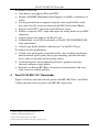
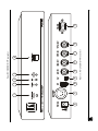
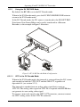
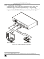
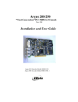
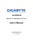
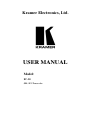
Kramer Electronics, Ltd.
USER MANUAL
Model:
FC-20
SDI / DV Transcoder
Contents
Contents
1
2
3
4
5
5.1
5.2
Introduction
Getting Started
Overview
Your FC-20 SDI / DV Transcoder
Connecting the FC-20 SDI / DV Transcoder
Powering the FC-20
MODE SELECT Dipswitch Settings
1
1
1
2
5
5
5
5.2.1
5.2.2
5.2.3
Setting the Audio Group
Setting DV Audio Channels
Setting the VITC or the DVITC Signals
5
6
6
6
6.1
Operating Your FC-20 SDI / DV Transcoder
Understanding the FC-20 LEDs
7
7
6.1.1
6.1.2
6.1.3
The POWER ON LED
The SDI IN LED
The DV DECODE LED
7
7
7
6.2
Understanding the DV DECODE / ENCODE MODES
7
6.2.1
6.2.2
Using the DV DECODE Mode
Using the DV ENCODE Mode
8
9
7
Technical Specifications
10
Figures
Figure 1: FC-20 SDI / DV Transcoder
Figure 2: FC-20 DV Decode Mode Configuration
Figure 3: FC-20 DV Encode Mode Configuration
3
8
9
Tables
Table 1: Front Panel FC-20 SDI / DV Transcoder Features
Table 2: Rear Panel FC-20 SDI / DV Transcoder Features
Table 3: FC-20 Audio Group Dipswitch Settings
Table 4: Technical Specifications of the FC-20 SDI / DV Transcoder
4
4
5
10
i
ADDENDUM (this data is included at the end of the Overview section)
This addendum adds the following information to the user manual:
Caution – No operator-serviceable parts inside unit.
Warning – Use only the Kramer Electronics input power
wall adapter that is provided with this unit1.
Warning – Disconnect power and unplug unit from wall
before installing or removing device or servicing unit.
1 For example: model number AD2512C, part number 2535-000251
2900-9999992
A1
Introduction
1
Introduction
Welcome to Kramer Electronics (since 1981): a world of unique, creative and
affordable solutions to the infinite range of problems that confront the video,
audio and presentation professional on a daily basis. In recent years, we have
redesigned and upgraded most of our line, making the best even better! Our
350-plus different models now appear in 8 Groups1, which are clearly defined
by function.
Congratulations on purchasing your Kramer FC-20 SDI / DV Transcoder.
This product is ideal for the following typical applications:
Live broadcast (remote control)
Editing and duplication studios
Interfacing between machines with differing formats
Seamless conversion from DV to SDI or from SDI to DV
The package includes the following items:
FC-20 SDI / DV Transcoder
Power adapter (12V DC Input)
This user manual2
2
Getting Started
We recommend that you:
Unpack the equipment carefully and save the original box and packaging
materials for possible future shipment
Review the contents of this user manual
3
Overview
The Kramer FC-20 SDI / DV Transcoder is a portable DV to SDI
bi-directional professional video converter with embedded audio. The FC-20
is designed for use in the editing studio, for live broadcasting, and for any
application requiring real-time transcoding between DV and SDI.
1 GROUP 1: Distribution Amplifiers; GROUP 2: Video and Audio Switchers, Matrix Switchers and Controllers; GROUP 3:
Video, Audio, VGA/XGA Processors; GROUP 4: Interfaces and Sync Processors; GROUP 5: Twisted Pair Interfaces;
GROUP 6: Accessories and Rack Adapters; GROUP 7: Scan Converters and Scalers; and GROUP 8: Cables and Connectors
2 Download up-to-date Kramer user manuals from our Web site at http://www.kramerelectronics.com
1
Your FC-20 SDI / DV Transcoder
In addition, the FC-20:
Auto-detects and supports PAL and NTSC
Includes AES/EBU Embedded Audio Support (at 48kHz, synchronous to
video)
Can be powered from a computer using the same 6-pin FireWire cable
that carries the DV stream in and out of the NLE (Non-Linear-Editor)
Supports the DVITC1 time code in the SDI data stream
Features a separate VITC2 input and output for analog decks via two BNC
connectors
Supports linear time code via the RS-422 port
Is controllable via an NLE or manually via the DV ENCODE/DECODE
front panel button3
Controls tape decks and other video devices4 via the RS-422 port
To achieve the best performance:
Connect only good quality connection cables, thus avoiding interference,
deterioration in signal quality due to poor matching, and elevated noise
levels (often associated with low quality cables)
Avoid interference from neighboring electrical appliances that may
adversely influence signal quality
Position your Kramer FC-20 in a location free from moisture and away
from excessive sunlight and dust
4
Your FC-20 SDI / DV Transcoder
Figure 1 illustrates the front and rear panels of the FC-20. Table 1 and Table
2 define the front and rear panels of the FC-20, respectively.
1 DVITC is Digital Vertical Interval Time Code
2 VITC is Vertical Interval Time Code
3 To be used only when there is no NLE
4 Only devices that conform to the Sony control protocol
2
KRAMER: SIMPLE CREATIVE TECHNOLOGY
6
1
7
8
2
9
4
10
11
5
12
Figure 1: FC-20 SDI / DV Transcoder
3
Your FC-20 SDI / DV Transcoder
13
14
3
Your FC-20 SDI / DV Transcoder
Table 1: Front Panel FC-20 SDI / DV Transcoder Features
#
1
Feature
1
Function
2
2
3
DV ENCODE /DECODE
Button
POWER ON LED
SDI IN LED
4
5
DV DECODE LED
MODE SELECT Dipswitches
Press to toggle between the decode (default) and the encode modes
3
Illuminates when the machine is powered
Illuminates when SDI framing is received in the DV Encode mode and
when DV framing is received in the DV Decode mode
Illuminates when in the DV Decode mode
For machine setup (1 and 2 are for audio group selection; 3 is for
channel pair selection; 4 is for VITC or DVITC timecode selection)
Table 2: Rear Panel FC-20 SDI / DV Transcoder Features
#
6
7
8
Feature
12V DC
BATTERY XLR
DV 6-pin port (FireWire)
Function
+12V DC connector for powering the unit
Connects to a portable battery pack input
Connects to a source or an acceptor for DV decoding or encoding
and/or power via 1394a bus
Connects to a source or an acceptor for DV decoding or encoding
Connects to the digital video BNC source, when selecting SDI as the
input
Connects to the digital video BNC output
9
10
DV 4-pin port (FireWire)
SDI IN BNC Connector
11
12
13
14
SDI OUT BNC Connector
VITC IN BNC Connector
Connects to the Vertical Interval Time Code IO
VITC OUT BNC Connector
RS-422 DB9C Port
Connects to control devices that conform to the Sony control protocol
1 In the DV Encode mode, SDI signals are converted to DV
2 In the DV Decode mode, DV signals are converted to SDI
3 Manual override
4
KRAMER: SIMPLE CREATIVE TECHNOLOGY
Connecting the FC-20 SDI / DV Transcoder
5
Connecting the FC-20 SDI / DV Transcoder
To connect the FC-20, do the following:
Connect the SDI/DV inputs and outputs as required1 (see section 6.2)
Connect a Sony RS-422 controlled deck, if required
Connect the power source (see section 5.1)
Set the MODE SELECT dipswitches (see section 5.2)
5.1 Powering the FC-20
The FC-20 features three power options for your convenience:
An XLR 12V battery pack input
A Universal DC Power Adapter
Bus power (via 6-pin FireWire input port)
Power sources are wired in parallel, therefore power is available from any
source at any time. For example, when more than one power source is
connected to the FC-20 unit, the source with the highest voltage takes over2.
5.2 MODE SELECT Dipswitch Settings
Use the 4-pin dipswitches on the front panel to select the desired operation
mode of the FC-20.
5.2.1
Setting the Audio Group
Dipswitches 1 and 2 are designated for audio group selection: A group of four
audio signals are embedded in the serial digital video bitstream. You may
select the audio group according to the settings in Table 3.
Table 3: FC-20 Audio Group Dipswitch Settings
Audio
Group
Dipswitch
1
2
1
ON
ON
2
OFF
ON
3
ON
OFF
4
OFF
OFF
1 Switch OFF the power on each device before connecting it to your FC-20
2 If you have a laptop connected to your FC-20 and the XLR battery connected too, if the battery voltage dips, the laptop will
take over and vice versa
5
Connecting the FC-20 SDI / DV Transcoder
5.2.2
Setting DV Audio Channels
Each group usually consists of four audio channels (or two stereo pairs).
To select the desired pair:
Set dipswitch # 3 to ON for: 1=Left/2=Right; or
Set dipswitch # 3 to OFF for: 3=Left/4=Right
5.2.3
Setting the VITC or the DVITC Signals
The FC-20 supports DVITC embedded timecode and separate analog VITC
signals.
Dipswitch # 4 determines the source of the DVITC1 or VITC timecode:
Set dipswitch # 4 to ON for Analog VITC
Set dipswitch # 4 to OFF for DVITC (SDI)
1 Digital VITC embedded timecode
6
KRAMER: SIMPLE CREATIVE TECHNOLOGY
Operating Your FC-20 SDI / DV Transcoder
6
Operating Your FC-20 SDI / DV Transcoder
Operate your FC-20 via the NLE or the DV ENCODE/DECODE button after
setting the MODE SELECT dipswitches (see section 5.2).
6.1 Understanding the FC-20 LEDs
The FC-20 consists of three LEDs described in the following sections.
6.1.1
The POWER ON LED
The POWER ON LED illuminates after the machine has been turned on and
is ready for operation.
6.1.2
The SDI IN LED
The SDI IN LED illuminates when:
SDI framing is received in the DV Encode mode
DV framing is received in the DV Decode mode
6.1.3
The DV DECODE LED
The DV DECODE LED illuminates when the machine operates in the DV
Decode mode.
6.2 Understanding the DV DECODE / ENCODE MODES
You can use the FC-20 to convert DV to SDI signals or SDI to DV signals.
You can operate the FC-20 in one of two modes:
The DV DECODE Mode:
The FC-20 unit converts DV signals to SDI signals (see section 6.2.1)
The DV ENCODE Mode:
The FC-20 unit converts SDI signals to DV signals (see section 6.2.2)
Note that in both modes where an NLE is present, switching occurs automatically,
that is, via FCP commands, and so on.
If the camera connects directly to the deck, switching is manual (also, there is no
deck control when using camera <-> deck connectivity).
7
Operating Your FC-20 SDI / DV Transcoder
6.2.1
Using the DV DECODE Mode
By default, the FC-20 is set to the DV Decode mode.
When in the DV Encode mode, press the DV ENCODE/DECODE button to
return to the DV Decode mode.
In the DV Decode mode, the DV source is transferred to the SDI OUT BNC.
Data from a Non-Linear Editor can be easily transferred to a Betacam
Recorder, as the example in Figure 2 illustrates:
Non-Linear Editor
Betacam Recorder
Figure 2: FC-20 DV Decode Mode Configuration
6.2.1.1
VITC in the DV Decode Mode
When in the DV Decode mode, the timecode is extracted from the DV stream
and encoded on both the VITC OUT and the SDI OUT, regardless of
dipswitch # 4 (see section 5.2.3).
The timecode is encoded onto an analog video signal that is input on
VITC IN. The analog video signal on VITC IN is required since FC-20 does
not generate its own analog video signal.
To receive a time code signal at the VITC OUT connector, you must connect
the VITC analog source to the VITC IN connector.
8
KRAMER: SIMPLE CREATIVE TECHNOLOGY
Operating Your FC-20 SDI / DV Transcoder
6.2.2
Using the DV ENCODE Mode
In the DV Encode1 mode, an SDI signal is transcoded to the DV output. Data
from an SDI source (for example a Betacam Player) is converted and
transmits to an NLE or camera, as illustrated in Figure 3. When an SDI signal
is inputted into the FC-20, the SDI output works as a loop for this signal.
Non-Linear Editor
Betacam Player
Figure 3: FC-20 DV Encode Mode Configuration
1 Press the DV ENCODE/DECODE button to toggle to the DV Encode mode from the DV Decode (default) mode
9
Technical Specifications
6.2.2.1
VITC in the DV Encode Mode
When in the DV Encode mode, the timecode is encoded using the following
methods:
If dipswitch # 4 is set to VITC, then the analog VITC is extracted from
the VITC IN signal and encoded onto the DV stream
If dipswitch # 4 is set to DVITC, then the DVITC signal embedded in the
SDI stream is extracted and encoded onto the DV stream
If neither VITC nor DVITC are detected, the FC-20 encodes a free
running timecode onto the DV stream
7
Technical Specifications
Table 4 includes the technical specifications:
Table 4: Technical Specifications1 of the FC-20 SDI / DV Transcoder
INPUTS:
OUTPUTS:
TIME CODE:
DV PORTS:
CONTROL:
POWER SOURCE:
DIMENSIONS
WEIGHT:
ACCESSORIES:
1 SDI SMPTE-259M, ITU-R BT.601 on a BNC connector
1 VITC IN on a BNC connector
1 SDI SMPTE-259M, ITU-R BT.601 on a BNC connector
1 VITC OUT on a BNC connector
DVITC (SDI BNCs); VITC via separate BNCs, and, linear TC via RS-422
One 6-pin FireWire port; one 4-pin FireWire port
RS-422 on a DB-9F connector (Sony protocol)
Dipswitches for audio group selection and DVITC/VITC selection
12VDC, 320mA on DC connector, XLR connector and 6-pin 1394A connector
22cm x 18cm x 4.5cm (8.7” x 7” x 1.7”) W, D, H (half 19”, 1U)
1.2kg (2.6 lbs) approx.
Power Supply
1 Specifications are subject to change without notice
10
KRAMER: SIMPLE CREATIVE TECHNOLOGY
Technical Specifications
LIMITED WARRANTY
Kramer Electronics (hereafter Kramer) warrants this product free from defects in material and workmanship under the
following terms.
HOW LONG IS THE WARRANTY
Labor and parts are warranted for three years from the date of the first customer purchase.
WHO IS PROTECTED?
Only the first purchase customer may enforce this warranty.
WHAT IS COVERED AND WHAT IS NOT COVERED
Except as below, this warranty covers all defects in material or workmanship in this product. The following are not covered
by the warranty:
1.
2.
3.
Any product which is not distributed by Kramer, or which is not purchased from an authorized Kramer dealer. If you are
uncertain as to whether a dealer is authorized, please contact Kramer at one of the agents listed in the Web site
www.kramerelectronics.com.
Any product, on which the serial number has been defaced, modified or removed.
Damage, deterioration or malfunction resulting from:
i)
Accident, misuse, abuse, neglect, fire, water, lightning or other acts of nature
ii)
Product modification, or failure to follow instructions supplied with the product
iii)
Repair or attempted repair by anyone not authorized by Kramer
iv)
Any shipment of the product (claims must be presented to the carrier)
v)
Removal or installation of the product
vi)
Any other cause, which does not relate to a product defect
vii)
Cartons, equipment enclosures, cables or accessories used in conjunction with the product
WHAT WE WILL PAY FOR AND WHAT WE WILL NOT PAY FOR
We will pay labor and material expenses for covered items. We will not pay for the following:
1.
2.
3.
Removal or installations charges.
Costs of initial technical adjustments (set-up), including adjustment of user controls or programming. These costs are the
responsibility of the Kramer dealer from whom the product was purchased.
Shipping charges.
HOW YOU CAN GET WARRANTY SERVICE
1.
2.
3.
To obtain service on you product, you must take or ship it prepaid to any authorized Kramer service center.
Whenever warranty service is required, the original dated invoice (or a copy) must be presented as proof of warranty coverage,
and should be included in any shipment of the product. Please also include in any mailing a contact name, company, address, and
a description of the problem(s).
For the name of the nearest Kramer authorized service center, consult your authorized dealer.
LIMITATION OF IMPLIED WARRANTIES
All implied warranties, including warranties of merchantability and fitness for a particular purpose, are limited in duration to
the length of this warranty.
EXCLUSION OF DAMAGES
The liability of Kramer for any effective products is limited to the repair or replacement of the product at our option. Kramer
shall not be liable for:
1.
2.
Damage to other property caused by defects in this product, damages based upon inconvenience, loss of use of the product, loss
of time, commercial loss; or:
Any other damages, whether incidental, consequential or otherwise. Some countries may not allow limitations on how long an
implied warranty lasts and/or do not allow the exclusion or limitation of incidental or consequential damages, so the above
limitations and exclusions may not apply to you.
This warranty gives you specific legal rights, and you may also have other rights, which vary from place to place.
NOTE: All products returned to Kramer for service must have prior approval. This may be obtained from your dealer.
This equipment has been tested to determine compliance with the requirements of:
EN-50081:
"Electromagnetic compatibility (EMC);
generic emission standard.
Part 1: Residential, commercial and light industry"
EN-50082:
"Electromagnetic compatibility (EMC) generic immunity standard.
Part 1: Residential, commercial and light industry environment".
CFR-47:
FCC Rules and Regulations:
Part 15: “Radio frequency devices
Subpart B – Unintentional radiators”
CAUTION!
Servicing the machines can only be done by an authorized Kramer technician. Any user who makes changes or modifications to
the unit without the expressed approval of the manufacturer will void user authority to operate the equipment.
Use the supplied DC power supply to feed power to the machine.
Please use recommended interconnection cables to connect the machine to other components.
11
For the latest information on our products and a list of Kramer
distributors, visit our Web site: www.kramerelectronics.com,
where updates to this user manual may be found.
We welcome your questions, comments and feedback.
Kramer Electronics, Ltd.
Web site: www.kramerelectronics.com
E-mail: [email protected]
P/N: 2900-000047 REV 2