1
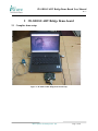
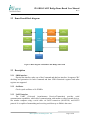
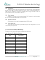
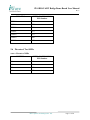
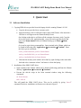
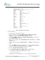
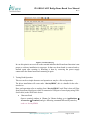
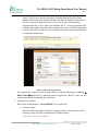
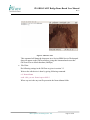
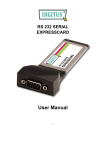
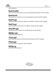
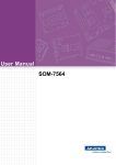
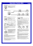
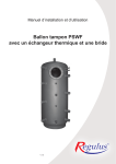
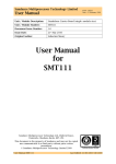
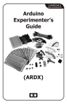
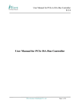
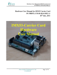
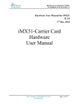
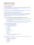
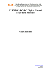
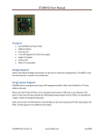
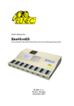
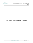
iW-SDIO-UART Bridge Demo Board User Manual R 1.2 iW-SDIO-UART Bridge Demo Board User Manual iWave Systems Technologies Pvt. Ltd. Page 1 of 20 iW-SDIO-UART Bridge Demo Board User Manual R 1.2 Table of Contents 1 INTRODUCTION________________________________________________________ 4 1.1 1.2 1.3 1.4 1.5 1.6 2 PURPOSE ____________________________________________________________ SCOPE ______________________________________________________________ OVERVIEW ___________________________________________________________ DEMO BOARD AND ACCESSORIES__________________________________________ SOFTWARE REQUIREMENTS ______________________________________________ PLATFORM HIGHLIGHTS _________________________________________________ 4 4 4 5 5 5 IW-SDIO-UART BRIDGE DEMO BOARD __________________________________ 7 2.1 COMPLETE DEMO SETUP _________________________________________________ 7 2.2 DEMO BOARD BLOCK DIAGRAM __________________________________________ 8 2.3 DESCRIPTION _________________________________________________________ 8 2.3.1 SDIO interface _____________________________________________________ 8 2.3.2 Oscillator _________________________________________________________ 8 2.3.3 UART interface _____________________________________________________ 8 2.3.4 USB interface ______________________________________________________ 9 2.3.5 JTAG connector ____________________________________________________ 9 2.3.6 Expansion connectors ________________________________________________ 9 2.3.7 Power adapter jack __________________________________________________ 9 2.4 PIN OUTS OF IW- SDIO-UART BRIDGE_____________________________________ 9 2.5 PIN OUTS OF GPIO ____________________________________________________ 10 2.6 PIN OUTS OF TEST LEDS _______________________________________________ 11 3 QUICK START _________________________________________________________ 12 3.1 3.2 3.3 SOFTWARE INSTALLATION ______________________________________________ 12 GTKTERM SETTINGS __________________________________________________ 14 DEMO BOARD TESTING PROCEDURE ______________________________________ 15 iWave Systems Technologies Pvt. Ltd. Page 2 of 20 iW-SDIO-UART Bridge Demo Board User Manual R 1.2 List of Figures Figure 1: Detailed view of iW-SDIO-UART Bridge demo Board ................................................. 4 Figure 2: iW-SDIO-UART Bridge demo board setup ................................................................... 7 Figure 3: Block diagram of iW-SDIO-UART Bridge demo board ................................................ 8 Figure 4: SDIO UART driver installation .................................................................................... 13 Figure 5: GtkTerm Settings .......................................................................................................... 15 Figure 6: Card insertion log .......................................................................................................... 16 Figure 7: Character read................................................................................................................ 17 Figure 8: File transfer in GtkTerm ................................................................................................ 18 Figure 9: Character write .............................................................................................................. 19 Figure 10: File capture in GtkTerm .............................................................................................. 20 List of Tables Table 1: Pin outs of iW- SDIO-UART Bridge ............................................................................... 9 Table 2: Pin outs of GPIO ............................................................................................................. 10 Table 3: Pin outs of LEDs ............................................................................................................. 11 iWave Systems Technologies Pvt. Ltd. Page 3 of 20 iW-SDIO-UART Bridge Demo Board User Manual R 1.2 1 Introduction 1.1 Purpose The purpose of this document is to explain the procedure to power-on and setting up the working environment of iW-SDIO-UART Bridge demo board. 1.2 Scope This document describes the Hardware connection procedure to power-on, inserting SDIOUART Bridge on the SD/MMC slot and establishes serial communication with PC/Laptop. This document also helps to perform the tests to verify the working of iW-SDIO-UART Bridge. 1.3 Overview Test LEDs GPIO connectors RS232 Serial port Interface SDIO Interface Clock crystal oscillator USB port Interface PROASIC3 A3P250PQPF 208 Power adapter jack(J5) JTAG connector Power LEDs Figure 1: Detailed view of iW-SDIO-UART Bridge demo Board iW-SDIO slave demo board can be used to evaluate SDIO to UART bridge, SDIO to USB bridge or SDIO to any custom logic/interface through expansion pins. The demo board also enables any designers seeking a development platform to validate their bridge cores. This versatility provides an ability to work with the SDIO bus and act as a useful bridge for target devices which require access to standard buses like UART, USB etc. The demo board comes preconfigured with an iW-SDIO-UART Bridge hardware reference design. iWave Systems Technologies Pvt. Ltd. Page 4 of 20 iW-SDIO-UART Bridge Demo Board User Manual R 1.2 Currently SDIO to UART bridge have been tested and proven using this demo board in Linux platform. The SDIO interface supported by the bridging applications enables a low-cost and small size implementation. A typical application includes a communication link between SDIO interface and devices like UART, USB, PHS, Bluetooth and Wi-Fi etc. 1.4 Demo Board and accessories o iW-SDIO-UART Bridge demo board o DC 5V Power supply o USB to serial converter cable 1.5 Software Requirements • A Laptop with SDIO slot and having linux Ubuntu 8.10 OS • SDIO-UART device driver (sdio_uart.ko file) • Serial port application such as GtkTerm or any other serial port application • Serial port application to test the demo board (sdio_rw.out file) 1.6 Platform highlights iW-SDIO-UART Bridge demo board consists of the following: General. o Actel ProASIC3 (A3P250-PQFP 208) o 18.432 MHz Clock crystal oscillator o UART transceiver(MAX3241) o USB transceiver(USB1T20) o 4 power LED outputs and 4 test LED outputs Connectors and interfaces: o SDIO interface o Power adapter jack (J5) iWave Systems Technologies Pvt. Ltd. Page 5 of 20 iW-SDIO-UART Bridge Demo Board User Manual R 1.2 o Flashpro3 Cable JTAG connector o RS-232 serial port o USB connector o FPGA I/O signals through Expansion Connectors iWave Systems Technologies Pvt. Ltd. Page 6 of 20 iW-SDIO-UART Bridge Demo Board User Manual R 1.2 2 iW-SDIO-UART Bridge Demo board 2.1 Complete demo setup Figure 2: iW-SDIO-UART Bridge demo board setup iWave Systems Technologies Pvt. Ltd. Page 7 of 20 iW-SDIO-UART Bridge Demo Board User Manual R 1.2 2.2 Demo Board Block diagram SDIO Interface JTAG Connector FPGA A3P250 UART Transceiver UART Connector USB Transceiver USB Connector Power adapter jack Expansion Connectors Oscillator Figure 3: Block diagram of iW-SDIO-UART Bridge demo board 2.3 Description 2.3.1 SDIO interface Physical bus interface takes care of the Command and data bus interface. It supports CRC checking and generation for both Command and data. SDIO Function0 registers and other registers are supported. 2.3.2 Oscillator Clock crystal oscillates at 18.432MHz 2.3.3 UART interface The UART (Universal Asynchronous Receiver/Transmitter) provides serial communication capabilities, which allow communication with modem or other external devices, like another computer using a serial cable via UART transceiver (MAX3241) and RS232 protocol. It is capable of transmitting and receiving serial data up to 1Mbit/s data rates. iWave Systems Technologies Pvt. Ltd. Page 8 of 20 iW-SDIO-UART Bridge Demo Board User Manual R 1.2 2.3.4 USB interface USB was designed to allow many peripherals to be connected using a single standardized interface socket. USB is intended to replace many legacy varieties of serial and parallel ports. USB transceiver (USB1T20) is capable of transmitting and receiving serial data at both full speed (12Mbit/s) and low speed (1.5Mbit/s) data rates. 2.3.5 JTAG connector Flashpro3 JTAG chain interface connected on this JTAG connector is used to program the FPGA by loading the programming files (STAPL/PDB). 2.3.6 Expansion connectors GPIO Headers 16x2 are used for debugging on board FPGA signals. 2.3.7 Power adapter jack Fixed-voltage versions TPS75233Q and TPS75215Q are used which provides 3.3 V and 1.5V, from the power input of 5V. 2.4 Pin outs of iW- SDIO-UART Bridge The pin outs of iW- SDIO-UART Bridge is as shown in the table below: Table 1: Pin outs of iW- SDIO-UART Bridge iW- SDIO-UART Bridge PINS A3P250 –PQPF 208 FPGA PIN numbers sys_rst_n_i 113 sd_clk_i 30 uart_dcd_i 147 uart_ri_i 149 sys_clk_i 202 sd_cmd_io 12 sd_data_io [2] 8 uart_dsr_i 148 uart_stx_o 152 sd_data_io[1] 46 uart_srx_i 145 iWave Systems Technologies Pvt. Ltd. Page 9 of 20 iW-SDIO-UART Bridge Demo Board User Manual R 1.2 iW- SDIO-UART Bridge PINS A3P250 –PQPF 208 FPGA PIN numbers uart_cts_i 146 sd_data_io[0] 44 uart_rts_o 151 uart_dtr_o 150 sd_data_io[3] 10 2.5 Pin outs of GPIO Table 2: Pin outs of GPIO GPIO PINS A3P250 –PQPF 208 FPGA PIN numbers GPIO1 198 GPIO2 197 GPIO3 196 GPIO4 194 GPIO5 193 GPIO6 192 GPIO7 191 GPIO8 190 GPIO9 189 GPIO10 188 GPIO11 184 GPIO12 183 GPIO13 182 GPIO14 181 GPIO15 180 GPIO16 179 GPIO17 177 iWave Systems Technologies Pvt. Ltd. Page 10 of 20 iW-SDIO-UART Bridge Demo Board User Manual R 1.2 GPIO PINS A3P250 –PQPF 208 FPGA PIN numbers GPIO18 176 GPIO19 175 GPIO20 174 GPIO21 173 GPIO22 172 GPIO23 168 GPIO22 167 2.6 Pin outs of Test LEDs Table 3: Pin outs of LEDs LEDPINS A3P250 –PQPF 208 FPGA PIN numbers D1 161 D2 160 D3 159 D4 158 iWave Systems Technologies Pvt. Ltd. Page 11 of 20 iW-SDIO-UART Bridge Demo Board User Manual R 1.2 3 Quick Start 3.1 Software Installation 1. Copying SDIO drivers provided in to the Laptop which is running Ubuntu 8.10 OS. • Copy the drivers provided in to a memory stick. • Insert the memory stick in USB slot of the Laptop with Ubuntu. After insertion a USB device will appear on the Ubuntu Desktop screen. On clicking on that device will show all the contents of memory stick. Copy the driver sdio_uart.ko file, application sdio_rw.out file and script sdio.sh file and paste in to /home/ubuntu folder (In Ubuntu Desktop go to Places Æ Home Folder). Or it can be copied using command line. Open terminal in the Ubuntu which can be found in following path “Applications Æ Accessories Æ Terminal”. Enter the below given commands. sudo cp /media/disk/sdio_uart.ko /home/ubuntu sudo cp /media/disk/sdio_rw.out /home/ubuntu sudo cp /media/disk/sdio.sh /home/ubuntu • Unmount the memory stick which can be done by right clicking on the removable disk and select “unmount volume” and remove it from the laptop. 2. Installation of the SDIO UART driver. • Open terminal in the Ubuntu which can be found in following path from the Ubuntu desktop “Applications Æ Accessories Æ Terminal”. • Execute the sdio.sh script in the linux terminal window using the following commands. cd /home/ubuntu sudo ./sdio.sh This will install the SDIO UART driver. This can be verified by giving “lsmod” command.The driver installation verification is as shown in Figure 3. iWave Systems Technologies Pvt. Ltd. Page 12 of 20 iW-SDIO-UART Bridge Demo Board User Manual R 1.2 Figure 4: SDIO UART driver installation 3. GtkTerm Installation • Provide internet connection to the Laptop. • In Ubuntu Desktop, Open Systems ÆAdministration Æ Synaptic Package Manager. It will open " Synaptic Package Manager " window. • Open Settings Æ Repositories in the Synaptic Package Manager window.It will open "Software Sources" window. • Enable all the options under "Downloadable from the internet" in "Ubuntu Software" Tab. • Enable all the options under "Ubuntu Updates" in "Updates" Tab and then give "OK" • Go to "Edit ÆReload Package Information" in " Synaptic Package Manager " window.It will update all the downloadable package information. • Exit the " Synaptic Package Manager " window. • Go to "Applications Æ Accessories Æ Terminal" in Ubuntu Desktop. Give following command to install gtkterm in the Terminal. sudo apt-get install gtkterm Installation can be verified by giving sudo gtkterm command in the terminal. iWave Systems Technologies Pvt. Ltd. Page 13 of 20 iW-SDIO-UART Bridge Demo Board User Manual R 1.2 3.2 GtkTerm Settings GtkTerm Settings are done in the Laptop runnning with Ubuntu. This application is used for the Demo board serial data transfer testing. • Open a terminal window in the Ubuntu, which is found in the following path Applications Æ Accessories Æ Terminal Give following command in the terminal sudo gtkterm This will launch GtkTerm application. • Do following settings in the GtkTerm. Open Configuration Æ Port in the GtkTerm. Port - /dev/ttyUSB0 Speed - 9600 Bits - 8 Parity - None Stop bits -1 Flow control - None iWave Systems Technologies Pvt. Ltd. Page 14 of 20 iW-SDIO-UART Bridge Demo Board User Manual R 1.2 Figure 5: GtkTerm Settings 3.3 Demo board Testing Procedure 1. SDIO driver (sdio_uart.ko) is installed in to the Laptop which is running with Ubuntu. Installation steps are given in the section 3.1 2. Connect the RS-232 serial cable to the Demo board and other end is connected to the USB port of Laptop using USB to Serial converter cable and GtkTerm settings are made as given in section 3.2. 3. Power ON the Demo board by connecting 5V power supply to the power jack of the Demo board. Make sure that the power LEDs D6, D7 and D8 should glow in the demo board. 4. Insert the Demo board in to the Laptop (Running with Ubuntu OS) SDIO slot. While Inserting in the SD/MMC slot Laptop LED should glow. Make sure that card insertion LED (D5) and power LEDs (D6, D7 and D8) are glowing in the demo board. The prints can be checked in terminal window by giving “dmesg” command. The terminal print is shown in the figure below. “mmc0: new SDIO card at address 0001” iWave Systems Technologies Pvt. Ltd. Page 15 of 20 iW-SDIO-UART Bridge Demo Board User Manual R 1.2 Figure 6: Card insertion log In case this print is not received on the terminal indicates that Demo board insertion is not proper or software installation is not proper. In that case demo board is removed and reinserted again after resetting it. Resetting is done by removing the power supply connected to the Demo board and connecting it again. 5. Testing Read Operation This test can be a simple character read operation or may be a file read operation. The driver installation will create node “/dev/ttySDIO0”, this is a handle for the sdio – uart device. Here read operation refers to reading from “/dev/ttySDIO0” node.That is data will flow from Demo board Serial port (which is connected to USB port of same laptop using USBSerial cable) to the SDIO slave device. • Character Read Open a terminal window in Ubuntu (In Ubuntu desktop go to Applications Æ Accessories Æ Terminal) and give following command followed by enter key. sudo cat /dev/ttySDIO0 iWave Systems Technologies Pvt. Ltd. Page 16 of 20 iW-SDIO-UART Bridge Demo Board User Manual R 1.2 This command will dump the incoming data from “/dev/ttySDIO” device (Sdiouart device) on the terminal window (TM1). Open a GtkTerm in the Laptop and follow the settings as mentioned in section 3.2. Figure 7: Character read Data input to the Demo board serial port is given by entering the characters followed by enter key in the GtkTerm application, since Demo board serial cable is connected to the Laptop using USB-Serial cable.The characters will appear in the Ubuntu terminal window (TM1). After completion of test “cat” command is killed by pressing CTRL-C keys in TM1. • File Read This is tested by sending the file from GtkTerm and capturing that in the terminal window in Ubuntu. In the Ubuntu Terminal window (TM1), execute command given below followed by enter key, which will dump the incoming data in sdio device to a file “cap.txt”. cd /home/ubuntu sudo ./sdio_rw.out /home/cap.txt 9600 0 In GtkTerm, go to “File Æ Send Raw File” Then select any text file to transfer, on clicking “OK” will trigger the transfer. iWave Systems Technologies Pvt. Ltd. Page 17 of 20 iW-SDIO-UART Bridge Demo Board User Manual R 1.2 Figure 7 given below showing procedure of sending dbg.txt file to the Demo module.After entering the command quickly file transfer should be started in the GtkTerm, otherwise application (sdio_rw.out) will be closed automatically. In application sdio_rw.out, 9600 is the baudrate and ‘0’ is for read operation.This read operation can be tested for higher baudrates (up to max 230400), but baudrate setting in the GtkTerm and sdio_rw.out application (need to pass desired baudrate as argument) should same. Figure 8: File transfer in GtkTerm The captured file “cap.txt” saved in home folder (In Ubuntu Desktop go to Places Æ Home FolderÆcap.txt) can be compared with the original file “dbg.txt” using text file comparison software or manually for verification. 6. Testing Write operation Write refers to data dump to “/dev/ttySDIO0” device (sdio-uart). • Character Write Keep the GtkTerm settings made before.Simple character write operation can be tested by giving following command in the Ubuntu terminal. sudo echo “abcd”>/dev/ttySDIO0 iWave Systems Technologies Pvt. Ltd. Page 18 of 20 iW-SDIO-UART Bridge Demo Board User Manual R 1.2 Figure 9: Character write This command will dump the characters in to /dev/ttySDIO0 device.The dumped data will appear on the GtkTerm.Before giving this command make sure that GtkTerm is set to default baudrate (9600bps). • File Write Do following settings in the GtkTerm as given in section 3.2. Write to the sdio-device is done by giving following command. cd /home/ubuntu sudo ./sdio_rw.out /home/cap.txt 9600 1 Where cap.txt is the any text file present in the /home/ubuntu folder. iWave Systems Technologies Pvt. Ltd. Page 19 of 20 iW-SDIO-UART Bridge Demo Board User Manual R 1.2 Figure 10: File capture in GtkTerm Once data dumped in /dev/ttySDIO0 device will appear in the GtkTerm window. This can be tested for different baudrates up to a maximum of 230400bps.But baudrate setting in the GtkTerm and sdio_rw.out application should be same. iWave Systems Technologies Pvt. Ltd. Page 20 of 20