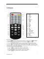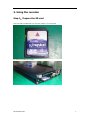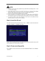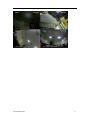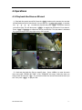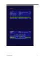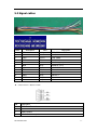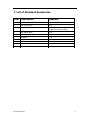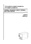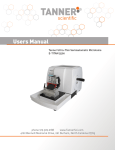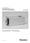
1
SD Video Recorder User’s Manual Thank you for using our Mobile DVR. This manual is applicable for MDR10x1, MDR10x2, MDR10x5, MDR30x1 and MDR30x5 series. Please read this User’s Manual carefully to ensure that you can use the device correctly and safely. The contents of this manual are subject to be changed without notice. SD Video Recorder 1- Warning This device is NOT of waterproof; to prevent it from any accident of fire or electric shock, please do NOT put any container with water on the device or nearby. Do not expose the device to moisture, or extreme temperatures. CAUTION RISK OF ELECTRIC SHOCK DO NOT OPEN This lightning flash with arrow symbol within an equilateral triangle is intended to alert users that there might be uninsulated dangerous voltage which may cause electric shock to person when the cover of device is opened. To prevent from the risk of electric shock, do NOT remove top cover or back cover. There is NO user-serviceable part inside. Ask for service from qualified maintenance man. The exclamation point within an equilateral triangle is intended to alert users the important operating and maintenance(servicing) instructions in this manual. Important notice: 1. 2. 3. 4. 5. 6. 7. 8. 9. 10. 11. 12. Please read over all cautions. Please keep this manual for reference in the future. Please notice all warning information. Please strictly follow the instructions in this manual while operating. Please NEVER put this device under the place which is easily poured by water. Please do NOT use abrasive chemicals, cleaning solvents or strong detergents to clean the device. Wipe the device with a soft and dry cloth. Please do NOT get the gate of airiness heat exchange closed. Please leave the device far away from hot and high temperature environment. Install the device with the accessories coming with it. Please take care when moving the device, make sure of security, and avoid being damaged by dropping from high place. Call for qualified maintenance man to repair when needed. The device can only be installed horizontally. Installed vertically or out of the horizontal could hurt person or damage the device or/and its parts. SD Video Recorder 2- 1.Main Features............................................................................................................................... 4 2. Overall description...................................................................................................................... 5 2.1 Front Panel..................................................................................................5 2.2 Rear panel ..................................................................................................6 2.3 Remote .......................................................................................................7 3. Using the recorder ....................................................................................................................... 8 Step 1:Prepare the SD card ..............................................................................8 Step 2, Connect camera. ....................................................................................9 Step 3, Connect to power supply.........................................................................9 Step 4, format the SD card ............................................................................... 10 Step 5, Choose recording quality ....................................................................... 10 Step 6, start recording ..................................................................................... 11 4.Operations .................................................................................................................................. 13 4.1 Play back the files on SD card ..................................................................... 13 4.2 Manage the power ..................................................................................... 15 5.Appendix, cables ........................................................................................................................ 18 5.1 Power supply ............................................................................................. 18 5.2 AV cables .................................................................................................. 18 5.3 Signal cables ............................................................................................. 20 6. Specification............................................................................................................................... 21 7. List of Standard Accessories..................................................................................................... 23 SD Video Recorder 3- 1.Main Features Video And Audio H.264 High Profile video compression, real time recording( 25 fps(PAL) / 30 fps(NTSC) for each channel. Frame rate adjustable for each channel. AAC(Advanced Audio Compression) for audio. D1 resolution for each channel, which means each channel support 704x576(PAL)/704x480(NTSC). Support 4 channel video and 4 channel audio recording; Power Input Support from +8V DC to +32VDC. Applicable for vehicles with +12V or +24V battery. When the power input connects in reverse polarity, the auto-protect function can prevent the recorder and battery from damage. The recorder provides each camera with stable +12V DC power; DVR can detect the short cut on power circuit. Can use ignition to control the power. Recording mode Continuous record. Start recording automatically when the DVR is turned on. Support schedule recording. Support alarm recording. Speed and Vehicle status recording Record vehicle speed and car id with audio and video. Support 6 sensors, can be connected to brake, return, right turn, left turn light etc. Over-speed alarm. SD card plug and play Support plug and play for SD card when not recording and playing. Note: If you remove the SD card while recording or playing, it might cause the damage of the file on SD card. While recording or playing, the yellow light on the front panel will be on. So please stop recording or playing until the yellow light is off if you need to remove the SD card. Multiple player supported You can use the following player to play back the record file. VLC media player(version1.0.0 or above) ; Storm player(Version 2009 or above) Winamp(Version 5.531 or above) SD Video Recorder 4- 2. Overall description 2.1 Front Panel 1 5 EX_IR USB 2.0 NET ⑥ ⑦ ⑧ RUN SD PWR ALARM SYS ① ② ③④ ⑤ ①:Power light. ②:Run light. ③:Alarm light. ④:SD present light. ⑤:System light. ⑥:External IR connector. ⑦:USB 2.0 port. ⑧:Lan port. Get to know the status of Mobile DVR by the indication of PWR light and RUN light: PWR RUN Description Always On Blinking DVR is turned on and running. Blinking with RUN by turns Blinking with PWR by turns Ignition is not enabled and DVR is turned off. Blinking together with RUN Blinking together with PWR Ignition is not enabled and DVR is running. The DVR will be turned off when it reached the “Ignition Power Off Delay” time. Blinking Off The DVR is turned off. It will restart if POWER button is pressed on the remote. Alarm light(yellow) Description On Alarm indication, such as overspeed. Off No alarm. SD Video Recorder 5- System light(yellow) Description On In recording. Don’t remove the SD card in this status. Please press “stop” on the remote to stop recording if you need remove the SD card. Removing SD card in this status might cause the damage on the record file. Off Recorder is not in recording mode. You can remove the SD card. 2.2 Rear panel ① ② ③ ④ ⑤ ⑥ ⑦ ①:AV input 1(including audio input 1, video input 1 and power for camera 1) ②:AV input 2(including audio input 1, video input 1 and power for camera 2) ③:AV input 3(including audio input 1, video input 1 and power for camera 3) ④:AV input 4(including audio input 1, video input 1 and power for camera 4) ⑤:AV ouput(including audio output, video output and power) ⑥:1 speed sensor, 3 sensors, 2 RS232 port, 1 RS485 port and one 5V DC output. ⑦:Power for the recorder and ACC input. SD Video Recorder 6- 2.3 Remote 1. 2. 3. 4. 5. 6. 7. 8. 9. 10. 11. 12. 13. 14. 15. 16. 17. 18. 19. 20. 21. Power Stop Record Alarm Play Numbers Audio Video Up Left Right Menu ESC OK Down Fast Forward Pause/Step Fast Backward OSD Next Previous How to use the remote: (1)Press <MENU> to enter main menu or sub menu. You can also use <MENU> to select among different value in the submenu. You can also use <MENU> as <OK>; (2)Press <Up/Down/Left/Right> button to move between the different menu item; (3)Press <OK> to save and exit the current menu. Press <ESC> to cancel and exit thecurrent menu. If you modify something in the menu, recorder will prompt a window to ask you to save or cancel your modification; (4)Press <VIDEO> to toggle among different video channel; (5)Press <AUDIO> to toggle among different audio channel; (6)To delete character in the edit control, you can press <Left>; (7)Press <POWER> for a while to turn on/off the recorder; SD Video Recorder 7- 3. Using the recorder Step 1:Prepare the SD card Select the SD card and make sure the lock jumper is in off position. Put the SD card into the recorder. SD Video Recorder 8- Step 2, Connect camera. Connect the camera as the picture shows. The yellow connector is for video and the white connector is for audio. Step 3, Connect to power supply Connect battery. ignition, used for battery. the red wire to the “+” pole of the battery and black wire to the “-“ pole of the The yellow wire is for connecting the ignition signal. If you don’t need to use connect the yellow wire to the “+” pole of the batery. Please note: The fuse is protecting the battery from shortcut so you need to connect the fuse near to the SD Video Recorder 9- NOTE 1. The DVR uses DC power input, please be very careful when connecting to the “+” and “-” of the power supply. 2. Wide voltage range of 8V-32V for the DVR. The DVR may be damaged if the voltage comes too high. And the DVR may not work if the voltage comes too low. 3. Power of the DVR should be supplied by the car battery. 4. Power consumption of the DVR can be 60W when the engine starts. All the cables for connecting from power to the DVR should be thick enough for current over 5 Amperes. 5. To protect the battery from being damaged of short circuit on the cable, the fuse should be placed very closed to the car battery. Step 4, format the SD card You need to format the SD card before using it. Press <MENU> to enter the main menu and select “FORMAT” in “STORAGE” sub menu. Choose “YES” to format the SD card. The format process will take some time and you will see the capacity of the SD card after formating. Step 5, Choose recording quality Press <MENU> to enter the main menu and select “RECORD SETTINGS” in the “RECORD” sub menu. SD Video Recorder 10 - The detailed parameters for each quality list as below: Quality Resolution Maxiam bit rate(Bit/s) Minumum bit rate (Bit/s) Audio Bitrate (Bit/s) Capacity need BASIC 2/3 D1 350K 210K 16K 119M/hour NORMAL D1 1000K 600K 16K 346M/hour GOOD D1 1200K 720K 16K 540M/hour HIGH D1 1500K 900K 16K 720M/hour NOTE:Maxiam write speed for most SD card is about 6000KBit/s, so please select “GOOD”or below if you are recording 4 channel video at same time. Step 6, start recording Press < REC> on the remote to start recording. There will be one red dot on each channel indicating the recording. The recorder will record all of the channel by default. If you need to record only one channel, use <UP/DOWN/LEFT/RIGHT> or number key “1”, “2” , “3” , “4” to select one channel and press < REC> to recording. SD Video Recorder 11 - SD Video Recorder 12 - 4.Operations 4.1 Play back the files on SD card (1)Play back the recent record file. Press the <PLAY> button on the remote, the recorder will play back the file for first channel. You can also use <UP/DOWN/LEFT/RIGHT> or number key “1” , “2” , “3” , “4” to select the channel and press <PLAY> to play the channel you want to play. You can also press <VIDEO> to toggle the full screen of one channel. Press <Next>/<Previous> to select the next or previous file. The play status is indicated by a green triangle on the top right corner of the screen. (2)Seek and play back the file at a specific time. Press <MENU> to enter the main menu and select “SEARCH BY TIME” in the “STORAGE” sub menu. Select the time you want to seek and choose <OK>. The recorder will list the record file around the time you set. Then press <PLAY> to play the file. SD Video Recorder 13 - SD Video Recorder 14 - 4.2 Manage the power (1)Use the ignition to control the power 1. Connect the ignition to the yellow wire of the power cable. And connect the red and black wire to the “+” and “-” pole of battery. Ignition Fuse Black wire + - Battery Red Yellow wire wire Recorder 2. Set the power off delay. Select “POWER OFF DELAY” in the “POWER” sub menu. The maxiam duration for the power off delay is 86400 seconds(24 hours). If the power off delay is set to 0, the recorder will turn off immidiately if the ignition is off. SD Video Recorder 15 - If the vehicle is using low level as ignition, you need to set the ignition signal to low level. (2)Turn on/off the recorder automatically 1. Connect the DVR to the battery. Please note that you need to connect the yellow wire (ignition wire) to the “+” pole (+12V or +24V) of the battery. Fuse Red Black + - Battery SD Video Recorder wire Yellow wire wire Recorder 16 - 2. Select “POWER ON” and “POWER OFF” in the “Power” sub menu and set the time you want to turn on/off the recorder. If you don’t need to turn on/off the recorder automatically, set the “POWER ON” and “POWER OFF” time to “00:00”. SD Video Recorder 17 - 5.Appendix, cables 5.1 Power supply Mark Color Description PWR RED “+” of power supply ACC YELLOW Ignition signal. Connect this wire to “+” of power supply if you don’t use ignition to control the power. GND BLACK “-“ of poer supply 5.2 AV cables 1) AV cables SD Video Recorder 18 - Mark Description VIN Video input AIN Audio input 12V Power output for camera(+12 VDC, Maximum current 1A) GND Ground 2)Audio output line Mark Description VO Video out AO Audio out 12V Power output for camera(+12 VDC, Maximum current 0.5A) GND Ground SD Video Recorder 19 - 5.3 Signal cables Mark Description Color Orange Description TXD, COM1, (GPS) RXD, COM1, (GPS) 1 TXD1 2 RXD1 3 TXD2 Brown Yellow 4 RXD2 Blue RXD, COM2 5 485A White RS485 A, (PTZ) 6 485B Grey RX485 B, (PTZ) 7 5.0V Red +5 VDC 8 GND Black Ground 9 SNR2 Grey Sensor 2 10 SNR3 Grey Sensor 3 11 SPEED Purple Speed sensor 12 SNR1 Grey Sensor 1 TXD, COM2 GPS connector(RS232 COM1) PIN Description 2 TXD: Data Transmit 3 RXD: Data receive 5 GND: Ground 9 +5V DC: Power output SD Video Recorder 20 - 6. Specification Item System Video Audio Storage Parameter Description Language Chinse Simplified/Chinese Traditional/English/Japanese Interface Graphical User Interface Security Administor and user password protected Video Input 1/2/4 channel video input, 1.0V, p-p,75Ω,BNC Video Output 1 channel vidoe output, 1.0V, p-p,75Ω,BNC Display 1/2/4 channel display Video Standard PAL (25fps) NTSC (30fps) Audio Input 1/2/4 channel audio input, 20KΩ,RCA Audio Output 1 channel audio output, 500Ω,RCA Output level 1V ~2V, p-p Recording mode Audio and video synchonize Compression AAC Video Compression H.264 High Profile Resolution D1 at 100fps(PAL)OR D1 at 120fps(NTSC) Video bitrate D1: 200Kbps ~ 2Mbps Audio bitrate 8KB/s Storage SD card,USB2.0 port(For flash disk or hard drive) Format AVI Sensor Sensors 1 speed sensor, 1 ignition sensor, 3 common use senseors COM Two RS232 connector and one RS485 connector Network RJ45,10M/100M Lan port Communication GPS supported Software Player rd 3 party player SD Video Recorder VLC media player,Storm player,WINAMP 21 - Firmware update Power Via SD card orUSB disk Power input DC:+8V ~ +32V Power output [email protected];+5V@1A Power consumption Less than 5W;less than 0.1W in standby mode Working temperature -10℃ ~ +60℃ Size 9.2CM(Width)×2.0CM(Height)×11.5CM(Depth) SD Video Recorder 22 - 7. List of Standard Accessories Item Description Quantity 1 1 pc 2 SD Video recorder Mounting bracket 3 AV input cable 1 pc for one/two channel SDVR, 2 pcs for four channel SDVR 3 AV output cable 1 pc 4 Signal cables 1 pc 5 Remote 1 pc 7 Fuse box 1 pc 8 1.5A fuse 2 pc 9 Screws 4 pc 11 Power cable 1 pc SD Video Recorder 2 pc 23 -