1
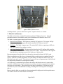
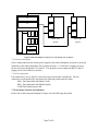
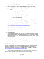
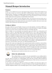
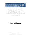
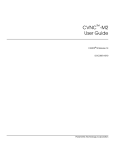
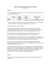
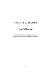
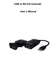
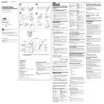
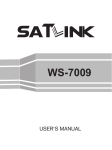
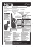
Mark 6 System User’s Manual
19 November 2013
1. Introduction
The Mark 6 disk-based has been developed as the next-generation disk-based VLBI dataacquisition system, with the following characteristics:
•
•
•
•
•
•
•
•
•
•
•
•
•
•
•
•
•
Four 10GigE input ports
Supports up to four Mark 6 8-disk modules for recording/playback
8Gbps aggregate sustained record capability (to two 8-disk modules)
16Gbps aggregate sustained record capability (to four 8-disk modules)
‘Burst-mode’ support, limited only by amount of installed RAM memory, supports highdata-rate, low-duty-cycle observations to fewer disk modules
Based on inexpensive high-performance COTS hardware
Easily upgradeable hardware on Moore's Law curve
Linux OS (Debian Squeeze 6.0.3)
Supports VLBI data formats VDIF and Mark5B
Fully open-source software (C and Python), downloadable from Haystack web site
VSI-S and XML command set support
‘Scatter/gather’ file system to manage slow and/or failed disks
Playback support on DiFX correlator
Smooth transition from Mark 5
Preserve as much investment in existing Mark 5 systems as possible
Existing Mark 5x systems are upgradeable to Mark 6 compatibility
Existing Mark 5 SATA disk modules are upgradeable to Mark 6 compatibility
2. Physical characteristics
The Mark 6 system is outwardly similar to Mark 5 systems, with the following differences:
1. The upper 5U chassis is called the ‘system chassis’ that accommodates two Mark 6 disk
modules and houses all data electronics.
2. The lower 5U chassis is called an ‘expansion chassis’ that contains only a power supply
and accommodates two additional Mark 6 disk modules.
3. A 1U ‘cable tray’ situated between the ‘system’ and ‘expansion’ chasses manages eight
mini-SAS high-speed data cables that plug in to the front panels of the mounted disk
modules.
Page 1 of 11
Figure 1 Mark 6 system front-view
An 8Gbps Mark 6 system is identical except the ‘expansion chassis’ is omitted.
3. Mark 6 Architecture
The Mark 6 is based on a standard PC platform and that COTS data electronic. Only the
mechanical chasses, disk modules, and a power-distribution PCB board are non-COTS.
The Mark 6 system supports three physical interfaces:
1. Data Port/10G Ethernet: These ports are presently 10G optical or CX-4 copper 10GigE
Ethernet interfaces that support the industry-standard 10G Ethernet interface.
2. Disk array: The Mark 6 supports up to 32 standard SATA disks or (spinning or SSDs) in
four 8-disk modules for reading or writing.
3. mini-Serial-Attached-SCSI: The data interface from the host PC platform disk controller
card to the disk modules is via standard ‘mini-SAS’ cables. Each mini-SAS cable supports
four disk drives, requiring two mini-SAS cables per 8-disk module.
Data input/output to/from the Mark 6 are through two internal dual-input 10G NIC cards.
When recording data to disks, the set of mounted disks records data uses a standard Linux file
system. Scans are recorded sequentially, one after another, but unlike the Mark5 series, any
individual scan can be erased. The removal of scans will cause a fragmentation of the disks and
may impact the performance of subsequent recording.
A scan directory is maintained by the Mark 6 that allows individual scans to be named when
recorded. Individual scans may be randomly accessed by scan name or sequential scan number
when not in a record mode. All or part of any scan may be reproduced. The data set may be
extended at any time with additional recording, including after removing and re-inserting the
disk set.
Data recorded to disks are recorded in a format optimized for high-speed real-time performance.
The number of disks in a disk module is normally 8.
Page 2 of 11
4. Data-recording (DIM) operation
The Mark 6 system, like the Mark5C, expects the external data source(s) to be responsible for
creating fully formatted and time-tagged Ethernet data packets (typically VDIF or Mark5B-overEthernet). Examples of such data sources are VLBI digital backend (DBE) subsystems such as
DBBC or ROACH-based DBE, among others. Figure 2 shows a simple block diagram with two
ROACH-based DBEs backends supplying data to a Mark 6 over two 10GigE connections.
The Mark 6 command software suite consists of two major software modules, one the ‘control
plane’ (cplane) and the other the ‘data plane’ (dplane), with a messaging system connecting
them. The cplane software receives VSI commands, validates and interprets, and directly
executes a subset of these commands that are non-real-time critical, then passes
information/commands to/from dplane as required. Normally, only the cplane interacts directly
with the user.
Roach Based
Digital Backend
Roach Based
Digital Backend
2 x 10G Optical
Ethernet fibers
Mark 6 Controller (5U chassis)
SAS2-SF-8080
Connector
Mark6
Disk
Module
(8pack)
Mark6
Disk
Module
(8pack)
Mark6
Disk
Module
(8pack)
Mark6
Disk
Module
(8pack)
Figure 2 Simplified block diagram of the RDBE and Mark 6
The Ethernet VLBI data frames may be encapsulated either within standard UDP/IP headers or
with only a MAC Ethernet Layer 2 header.
4.1 Time-keeping
The Mark 6, like the Mark5C, is not data-time aware. Data packets arriving from the data
source(s) must already be fully time-tagged and formatted.
4.2 Setup for normal data acquisition
There are two main steps for setting up the Mark 6 for normal data-acquisition:
1. Module/group preparation
2. Configuration of network interfaces
4.2.1 Module Preparation
The Mark 6 system defines a set of one or more modules as a ‘group’ that act as a single entity
for recording and playback and must always be kept together until explicitly dissolved.
Page 3 of 11
There are three steps for defining a new ‘group’ (see the Mark 6 Command Set document for
more detailed information):
1. For each module: Insert the module in any slot in the Mark 6, connect the associated SAS
data cables (make sure cable goes to the assigned module and connector), turn ‘on’ the
keyswitch and wait a few seconds for the module to come to life.
2. For each module to be included in the ‘group’: Use the ‘mod_init’ command, which takes
two actions:
a. Assigns a Module Serial Number (MSN) to a new (i.e. previously uninitialized)
module.
b. Unconditionally erases all existing data on the module
3. Use the ‘group’ command to define a ‘group’ of modules that work as a single entity
during the recording/playback process. When mounted, a ‘group’ is referred to by a
contiguous set of numbers (usually, but not necessary, in ascending order) of the slot#’s
in which the modules reside; for example, group ‘1’ refers to a single-module group
composed of the module residing in slot# 1, group ‘1234’ or ‘1243’ refers to a group
composed of modules residing in slot#’s 1,2,3,4. Up to four modules may be included in
a group.
At this point, an mstat command can be issued to confirm the creation of the group and provide
many details, as shown in Table 1 as an example.
mstat?all;
Get info on all mounted modules
Group
Slot
#
eMSN
#disks
found
#disks
registered
GB
(rem)
GB
(total)
Status1
Status2
Type
1234
1234
1234
1234
1
2
3
4
QRS00450/16/4/SG
QRS00451/16/4/SG
QRS00452/16/4/SG
QRS00453/16/4/SG
8
8
8
8
8
8
8
8
16000
16000
16000
16000
16000
16000
16000
16000
unmounted
unmounted
unmounted
unmounted
null
null
null
null
SG
SG
SG
SG
Table 1: Example response from 'mstat?' query for a newly initialized 4-module 'group'
(see Mark 6 Command Set for details)
The modules in slot#s 1,2,3&4 are an existing complete unmounted group that has previously
been assembled and initialized. The first step is to mount the group using the group command.
group = mount: 1234;
Mount all 32 disks in the four modules
Once the group is mounted, the status1 field is updated to “mounted”, while the status2 field set
to inform if the group has been “protected” or “unprotected”. For this case, it is assumed to be
“unprotected”. After the mount is completed successfully, the group can be “opened”. This will
designate the group as the primary disk modules for recording and playback operations.
group = open: 1234;
Open all 32 disks for record capabilities
If there is any data on the modules, it may be erased, or the data appended. If the data is to be
erased, the entire group must be chosen:
group = unprotect : 1234 ;
Must unprotect immediately before
erase
group = erase : 1234;
Erase; group 1234 is now erased
and available
Page 4 of 11
Note: The erasing of the module uses the standard Linux command and depending on the
amount of data stored, may take some time to complete.
mstat?all;
Get status of all modules/groups
Group
Slot
#
eMSN
#disks
found
#disks
registered
GB
(rem)
GB
(total)
Status1
Status2
Type
1234
1234
1234
1234
1
2
3
4
QRS00450/16/4/SG
QRS00451/16/4/SG
QRS00452/16/4/SG
QRS00453/16/4/SG
8
8
8
8
8
8
8
8
16000
16000
16000
16000
16000
16000
16000
16000
open
open
open
open
ready
ready
ready
ready
SG
SG
SG
SG
The 4-module group is now standing by and ready to be recorded on.
4.2.2 Network Interface Configuration
The Mark 6 provides the capability to strip away any non-VLBI headers that are required for
data transport over a standard IP infrastructure and filter unwanted packets received over the 10G
Ethernet interface. Therefore the first step for the Mark 6 is the setting up the input streams that
data will be arriving on. For previous systems, this required 2 or more commands. For the Mark
6 a single command will identify the interfaces, specify the payload format and provide the offset
parameters for normal data-acquisition. To configure the interfaces, the input_stream command
provides the mechanism for interface configuration. An example for setting up two 8Gbps
stream is shown.
The first step is to define the input data streams, source, data format, packet characteristics and
source-IP address and inform cplane it is to be added (note, these two commands can be
combined into a single command):
input_stream = add : RDBE1 : vdif : 8224 : 42: 36 : eth0: 192.162.1.38 ;
input_stream = add : RDBE2 : vdif : 8224 : 42: 36 : eth1 : 192.162.1.40 ;
The input_stream command identifies the payload format, vdif, the length of the VLBI payload
to be expected, 8224 bytes, the offset over the UDP/IP/MAC headers to the VLBI payload, 42
bytes and the byte offset to the packet serial number and the interface it is expected on.
The final step is to commit the changes to dplane:
input_stream = commit ;
The Mark 6 system is now properly configured for receiving and recording data.
4.3 Operation during data-acquisition
After the Mark 6 is properly setup, data acquisition occurs whenever the record command is
received and the specific timing criterion is met. If data exist on the 10G Ethernet interface and
the ‘record’ is made active, the data are written to the disk module(s) in the ‘active’ group. If no
data are seen on the interface, or the packet criteria are not meet, no data are written to disk.
Since the Mark 6 Linux operating system is not a real-time operating system, no guarantees can
be made for precise gating on the recorder; however, packet inspection can guarantee that the
recordings start on integer seconds.
Data-acquisition stops if the end time criteria is meet or following the receipt of a request to stop
data collection, record=off.
Page 5 of 11
5. DOM operation
Playback from a Mark 6 is normally expected to be to a software correlator. The operation of the
DOM function to use cplane to mount the experiments disks with the group command and read
the data from the disks as standard Linux files using the gather or the gator applications (Section
9). A layer of software using FUSE or other stand alone applications will be available to allow
simple access to data on the disks and make the data appear as a single file.
6. Data format on Mark 6 disks
The Mark 6 hardware does not differentiate between the payloads received when recording to the
disk modules. The data format written to the disk modules is always VDIF. This restriction is
purely a function of the software and may change in later revisions (please refer to the release
notes on capabilities). VDIF frame formats are self contained and when transmitted over a
network is self contained within a jumbo frame length, < 9000 bytes. For this reason, when
using VDIF data an apriori knowledge of the framing is expected.
For Mark5B-format data, each 10016-byte Mark 5B data frame is divided into two 5008-byte
Ethernet frame before transmission to the Mark 6. Upon receipt by dplane, the packet is reassembled into a 10016 byte packet and then converted on-the-fly into a VDIF data frame before
recoding. The result is 10,000 bytes of data with a standard VDIF header (32 bytes) replacing
the Mark5B header (16 bytes). The original Mark5B header is retained and encapsulated into the
extended header (last four words) of the VDIF header.
7. Mark 6 Hardware
7.1 Internal Mark 6 Connections
The Mark 6 system contains standard COTS hardware except for the PCB required to only apply
power to the disk modules.
7.1.1 OS disk connections to motherboard
The Linux OS disk is configured as ‘Master’ and connects to the ‘Primary’ SATA connector on
the motherboard with a standard 7-pin SATA hard drive cable. Unlike Mark5, the HDD housing
is limited to a single disk, due to the CPU cooling fans on the motherboard located below the
HDD.
7.1.3 Chassis-backplane connections
Figure 3 shows the connections on the chassis backplane. Please refer to this figure in the
following discussion.
Page 6 of 11
J2
J1
J3
J10
J
4
J
5
J
6
J
7
J
8
J
9
J2
J2
J2
J3
J3
J4
J4
Slots 2&4
power
Slots 1&3
power
J12
J13
Figure 3 Chassis backplane connectors (as viewed from rear of chassis)
7.1.5 Power connections
Power connections from the chassis power supply to the chassis backplane are made via an 8-pin
connector on the chassis backplane J10 as shown in Figure 3. Connector J1 supplies power to
the two slot power backplane via J3 and J4. J2 is the power sense connection and J12 and J13
supply power to the banks key switches.
7.1.6 Fan connections
Fan connectors J3-J9 (see Figure 3) provide power to the module cooling fans. The fan
connectors are all identical; by convention, the following connections are made:
J5&8 Dual fans under disk Bank A (left)
J6&9 Dual fans under disk Bank B (right)
J3,4&7 Fans behind system disk
7.2 Front-Panel Controls and Indicators
Please refer to the front-panel diagram in Figure 4 for the following discussion.
Page 7 of 11
\
Figure 4 : Mark 6 Front Panel Layout
7.2.1 Power Switch and LED
The POWER switch applies power to the unit, illuminating the corresponding LED. If the
POWER switch is held depressed for several seconds while power is already applied, power will
be shut off.
7.2.2 Disk-Bank Switches and LED’s
Associated with each slot is one keyswitch and four LEDs. Their functions are explained in
Table 2:
Keyswitch
When moved to ‘locked’ position, physically locks the module into place; no
attempt should be made to remove the module when the keyswitch is in the
‘locked’ position.
When moved to ‘unlock’ position, physically unlocks module and removes power
from the module. The module should, via software, be dismounted before
initiating module power-down; under no circumstances should the keyswitch be
moved to the ‘unlock’ position while the module is actively recording or playing.
The module must not be physically removed until power is removed (‘Power’ LED
is off).
‘Locked’ LED (green)
Indicates keyswitch is in ‘locked’ position
‘Power’ LED (green)
Indicates power is applied to module; power is applied sequentially to four disks at
a time to reduce load on the power supply.
‘Ready’ LED (green)
Steady ‘on’ Indicates the module is now ready and accessible to the host bus
controller card.
‘Selected’ LED (red)
Not used at this time, there is no method to indicate visually that the module is
selected as ‘active’ module. The software must be queried to determine the state
of the module.
Table 2 Disk Slot Switches and Indicators During Operation
Page 8 of 11
7.2.3 Disk-Module LED’s
Each disk module has two sets of four LED’s; each LED indicates disk activity on a
corresponding disk. The association of LED’s to disk within the module location is shown in
Figure 5.
Figure 5: LED and disk positions in a Mark 6 disk module (front of disk module is to the left)
7.3 10G Ethernet cable-length restrictions
The Mark 6 utilizes standard NIC cards, and can support up to 15m for copper cables. For
optical fibers the length is dependent on the type of optical plugin used and its rated distance
maximum distance.
8. Mark 6 Software Support
8.1 Operating System
Each Mark 6 system is normally shipped with a full installation of Debian Linux and the current
version of Mark 6 software. However, each Mark 6 must be configured with an IP address and
domain name supplied by your system administrator. A convention has been adopted to assign
Mark 6 system names in the format ‘Mark 6-xxxx’ where ‘xxxx’ is the serial number of the
particular Mark 6 unit; it is preferable that you maintain that name as it helps to keep track of the
Mark 6 systems and their configurations. Instructions for local network, time-zone and NTP
configuration is available in the ‘getting started’ manual at
http://www.haystack.edu/tech/vlbi/mark6/documentation.html.
8.2 Mark 6 Software
The Mark 6 is comprised of two components, the control plane (cplane) and the data plane
(dplane). The programs may be downloaded and installed with a simple procedure. Detailed
information installing and updating the Mark 6 software is available in the ‘getting started’
manual at http://www.haystack.edu/tech/vlbi/mark6/documentation.html. For best operation of
the Mark 6 system, it is recommended that software be regularly updated.
Page 9 of 11
9. Utility and Test Programs
da-client –h <machine> - where <machine> is the target Mark 6 system (defaults to
localhost). Small standalone program 1 with a simple operator interface that allows
commands to be sent and responses to be received from cplane. cplane must be
running on <machine>.
dboss – dplane client. provides limited control of d-plane directly for recording data.
Executing dboss without any arguments will produce a help menu.
dpstat – monitors dplane UDP messages and displays status information (only)
dqa – data quality analyzer program. Can be run on any output data file; provides information
about file format and contents.
dspeed – rudimentary program to test disk performance
gather –reassembles scan data from a scatter-gather file system group of files originally written
by the Mark 6
gator – accesses (potentially multiple) Mark 6 scatter-gather file sets, re-assembles data as
necessary, and creates output file(s) on a destination fileserver (often RAID)
modspeed - set up a module and run scatspeed to measure disk performance
scatspeed - program to test multiple-disk scatter write performance on a mounted module
m6-erase – standalone disk-erase and disk-conditioning program
10.Operating the Mark 6 System
10.1 System Boot
Booting takes place automatically when power is turned on. On first boot-up, it is recommended
that a monitor and keyboard be attached so the boot-up can be observed. No intervention from
the keyboard should be necessary during the boot process; if keyboard intervention is necessary,
it may not be possible to boot the system ‘headless’ (without monitor or keyboard), which is
often the standard mode of operation. If you need help, please contact Chester “Chet” Ruszczyk
at Haystack ([email protected]).
If the system boots into X-windows, you must force a normal Linux prompt with
<Cntl><Alt><F1>.
10.2 Using cplane
The main Mark 6 DIM control program is called cplane, which must be started before the system
will respond to normal Mark 6 commands. cplane may be started either locally or remotely
through a terminal session.
1. Login name: oper
Login password: ------
(chosen by user)
Contact Chester Ruszczyk ([email protected]) for a password, if needed.
1
‘da-client’ may be run on the same computer as cplane or on a different computer. It connects to an m5drive tcp
socket on a prescribed computer with cplane running and accepts Mark 6 commands.
Page 10 of 11
2. Issue ‘script –f [filename]’ if you wish to retain a record of your session ( use ‘-af’ to
append to current file). Default file name is ‘typescript’ in the default directory.
3. Start cplane, which is the primary control program for the Mark 6 DIM system:
‘cplane –m [-1|0|1|2|3] –e [‘commands’] –s [1|2|3|4|5|6|7] &’ (defaults underlined)
where
m – message level (range –1 to 3, default 1)
-1 A vast quantity of debug
0 Some debug
1 Normal operation; warnings and errors
2 Only errors and operational messages
3 Only fatal errors when the program dies
& - runs cplane in background
4. Run ‘da-client’
da-client is a small standalone program 2 with a simple operator interface that allows
commands to be sent and responses to be received from cplane. It provides the operator
with a convenient ‘>’ prompt and accepts the normal Mark 6 commands, but does not
require the normal termination semi-colons required by VSI syntax. You may type any
command or query from Mark 6 command set
(http://www.haystack.edu/tech/vlbi/mark6/documentation.html)
Type ‘status?;’ to query system status.
Return should be ‘!status?=0:0x001;’ (0x001 indicates ‘ready’ status)
Important: Determine software version
Type ‘sys_info’?;’. This will also provide other useful information pertaining to the
system.
5. Program Shutdown:
To terminate dplane, from ‘da-client’, type dterm =1; This will cause cplane to send the
terminating string to dplane. Another option is to run dboss t 1. To exit from da-client,
simply type <Ctrl C> or ‘quit’. This should bring you back to a system prompt. To end
cplane, type ‘ecplane’.
6. System Shutdown:
From a local console, enter ‘halt’; system will halt but power will not shutdown.
From a local or remote console issue ‘su’ to become root, then use the normal Linux
shutdown ‘/sbin/shutdown –h now’; system will be halted and powered down. Root
password will be supplied on phone or e-mail request.
10.3 Mark 6 Control Syntax
The Mark 6 command and query syntax is based on the VSI-S syntax 3, which is worthwhile
becoming acquainted with if you wish to directly exercise the Mark 6system through its
command set. A summary of this syntax is given in the ‘Mark 6’ command set’ (available at
http://www.haystack.edu/tech/vlbi/mark6/documentation.html).
2
‘da-client’ can be run on the same computer as cplane or on a different computer. It connects to an
m5drive tcp socket on a prescribed computer with cplane running, accepts Mark 6 commands.
3
The full VSI-S specification is available at http://vlbi.org/vsi/. The Mark 6 application uses many VSI-S
commands, but is not fully VSI-S compliant.
Page 11 of 11