1
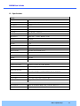
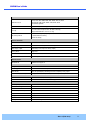
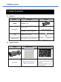
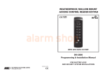
O2iB3M
Intensifier IP® Full HD Megapixel
xel Indoor/Outdoor
Bullet IP Camera with Motorized Lens
O2iB3M User ’s Guide
Directions
Be careful not to cause any physical damage by dropping or throwing the camera. Especially keep the
device out of reach from children.
Do not disassemble the camera. No after service is assumed when disassembled.
Use only power adapters compatible with the unit.
Be careful to prevent moisture or water penetration into the unit. Particular attention is needed when
installing the unit. The screw holes for the installation screws and pipe should be maintained water tight
during the whole life time of the product.
All the electrical connection wires running into the unit should be prepared so that water from the outside
cannot flow into the unit through the surface of the wires. Penetration of the moisture through the wire for
extended period can cause malfunction of the unit or deteriorated image.
Note
This equipment has been tested and found to comply with the limits for a Class A digital device,
pursuant to part 15 of the FCC Rules. These limits are designed to provide reasonable protection
against harmful interference in a residential installation. This equipment generate, uses and can
radiate radio frequency energy and, if not installed and used in accordance with the instructions, may
cause harmful interference to radio communications. However, there is no guarantee that interference
will not occur in a particular installation. If this equipment does cause harmful interference to radio or
television reception, which can be determined by turning the equipment off and on, the user is
encouraged to try to correct the interference by one or more of the following measures:
Reorient or relocate the receiving antenna.
Increase the separation between the equipment and receiver.
Connect the equipment into and outlet on a circuit different from that to which the receiver is
connected
Consult the dealer or an experienced radio/TV technician for help.
Caution
Any changes or modifications in construction of this device which are not explicitly approved by the
party responsible for compliance could void the user’s warranty.
Rev.1.0 (Feb. 2015)
2
O2iB3M User ’s Guide
Revision History
Date
Revision
th
1.0
Feb 25 , 2015
Details
First manual revision creation.
Rev.1.0 (Feb. 2015)
3
O2iB3M User ’s Guide
Contents
1.
2.
Introduction .................................................................................................................................................... 5
1.1.
Overview ............................................................................................................................................... 5
1.2.
Specifications ........................................................................................................................................ 6
1.3.
Applications of O2iB3M......................................................................................................................... 8
Product Description ...................................................................................................................................... 9
2.1.
Contents ................................................................................................................................................ 9
2.2.
Product Preview .................................................................................................................................... 9
2.3.
Physical description ............................................................................................................................ 10
2.4.
2.3.1.
External View ............................................................................................................................ 10
2.3.2.
Dimensions ............................................................................................................................... 10
2.3.3.
External Connector ................................................................................................................... 11
2.3.4.
Factory Default Switch .............................................................................................................. 11
Functional Description ........................................................................................................................ 12
3.
On Site Installation ...................................................................................................................................... 14
4.
Getting Started ............................................................................................................................................. 15
5.
4.1.
PC Requirement ................................................................................................................................. 15
4.2.
Quick Installation Guide ...................................................................................................................... 16
4.2.1.
Connect PC and O2iB3M to network........................................................................................ 16
4.2.2.
Install Speco-NVR and set IP parameters on O2iB3M ............................................................. 16
4.2.3.
Remote video connection to O2iB3M ....................................................................................... 18
4.2.4.
Additional settings through connection to the Admin Page ...................................................... 20
Troubleshooting ........................................................................................................................................... 21
5.1.
No power is applied ............................................................................................................................ 21
5.2.
Cannot connect to the Video............................................................................................................... 22
5.3.
Windows Vista or Windows 7.............................................................................................................. 23
5.4.
Technical Assistance ........................................................................................................................... 26
Appendix A – Important Notice in Exchanging SD Card (Micro SD)......................................................................... 27
Rev.1.0 (Feb. 2015)
4
O2iB3M User ’s Guide
1. Introduction
1.1. Overview
The ONSIP O2iB3M is a state-of-the-art mega-pixel, dual-codec (H.264, MJPEG) IP/network camera built with
embedded software and hardware technology. It enables real time transmission of synchronized video of Full
HD resolution and audio data. Remote clients can connect to ONSIP O2iB3M for the real time video/audio data
through various client solutions running on PC, PDA or mobile phones. Real time 2-way communication is
available through bidirectional audio communication feature.
Intensifier IP® technology is the most optimized solution for indoor and outdoor surveillance in low-light
conditions by using superior CMOS sensor with low-light sensitivity ISP sensor. Intensifier IP® is especially
beneficial in poor lighting environments, efficiently reducing noise and ghosting while maintain a color image
without the use of IR LEDs.
Designed to be a stand-alone streaming audio & video transmission device, ONSIP O2iB3M can be applied to
various application area such as video security, remote video monitoring, distance education, video conference
or internet broadcasting system.
IP66 compliant housing will extend the application area to harsh environments of wide temperature range.
Embedded PoE (Power over Ethernet, IEEE 802.3af) will enable the owner to reduce TCO (Total Cost of
Ownership) by reducing on-site wiring works for the installation.
Rev.1.0 (Feb. 2015)
5
O2iB3M User ’s Guide
1.2. Specifications
Camera
Image sensor
Progressive scan 1/3 inch CMOS 2M pixels
Full resolution
1,920 x 1,080 pixels (Full HD)
Sync System
Internal
Lens
2.8 ~ 11mm Motorized Focus & Zoom
Day & Night
AUTO, DAY, NIGHT
Sensitivity
Intensifier Max – 0.0005 Lux
Back Light Compensation
ON / OFF
White Balance
ATW(2.000K ~ 10,000K) / MANUAL / PUSH
Exposure
DC / ESC
WDR
ON / OFF
3D-DNR
0 ~ 20
Intensifier
AUTO ON (Max 128x) / OFF
Privacy Mask
ON / OFF (10 Programmable Zones)
Motion Detection
ON / OFF (4 Programmable Zones)
Digital Zoom
1x ~ 12x
Mirror
H / V / Rotate
DEFOG
ON / OFF
OSD
BUILT IN
Video
Compression method
Simultaneous Dual Codec (H.264 / MJPEG)
Resolution
1,920 x 1,080@30fps
Multi-Profile Streaming
- 5 simultaneous video profiles
- Select the codec type, resolution and frame rates for each profile.
Intelligent Bit-Rate Control
VBR or CBR
PTZ
Digital PTZ & Video crop
Image Setting
Text overlay, Privacy mask, De-interlace filter
Motion detection
3 regions
Audio
Mono Upstream
32Kbps G.726 ADPCM, 64Kbps 16bit µ-law PCM ~ MIC/Line-in
Mono Downstream
64Kbps 16bit µ-law PCM ~ Line-out
Rev.1.0 (Feb. 2015)
6
O2iB3M User ’s Guide
Network
Network Protocol
- IPv4, TCP, UDP, IGMP, ICMP, ARP, RARP, PPPoE, RTCP
- RTP, RTSP, SDP, HTTP, SMTP, FTP, DHCP, UPnP
- NTP, DNS, DynDNS
Dynamic IP
Speco DDNS (free of charge)
Security
- User ID & Password protection, IP address filtering
- Digest Authentication, User Access Log
Streaming method
- RTSP streaming with proprietary format for control information
- standard RTSP streaming
- HTTP streaming
External Terminals
LAN
10/100BaseT LAN (auto MDIX)
Analog output
1 channel D1 CVBS output of the encoding video
Alarm input / output
Alarm I/O (1 Sensor input & 1 Relay output)
Factory Reset
Supported
Audio
MIC/Line in, Line out
Power
DC 12V input
Alternate Power
Standard PoE
IEEE802.3af Supported
Alarm & Event
Intelligent Video
Motion Detection
Alarm Triggers
Motion Detection + Sensor Input
Alarm Events
Video file upload(FTP), Still Image transmission(Email), Relay output
Alarm Buffer (Audio/Video)
Configurable Pre-alarm (5~15 sec) & Post-alarm (10~60 sec)
Client Software
Speco NVR
Windows XP/Vista/7 (free of charge)
Speco ONSIP
Android™, iPhone®, iPad® (free of charge)
Miscellaneous
Operating Temperature
-10°C ~ 50°C
Operation Humidity
8 ~ 80% RH
Power
DC 12V, 0.6A
Dimensions(W x H x D)
Ø99.9mm x 254.4mm
Weight
1.1kg
Casing
AL, PC, Vandal resistant, IP66
Approvals
FCC, RoHS
Package information
Unit, CD, mounting screws
Rev.1.0 (Feb. 2015)
7
O2iB3M User ’s Guide
1.3. Applications of O2iB3M
Security surveillance (buildings, stores, manufacturing facilities, parking lots, banks, government facilities,
military, etc.)
Remote monitoring (hospitals, kindergartens, traffic, public areas, etc.)
Teleconference (Bi-directional audio conference). Remote Learning, Internet broadcasting
Weather and environmental observation
Rev.1.0 (Feb. 2015)
8
O2iB3M User ’s Guide
2. Product Description
2.1. Contents
The product package contains followings :
Contents
O2iB3M
Description
Remarks
O2iB3M main unit
Screws ((2 type)
Accessories
L-type
type wrench (2 type), CVBS Cable
CD
Reference Guide
Software & User’s Guide
Quick installation guide,
guide Guide pattern
2.2. Product Preview
O2iB3M
Camera Unit
ONSIP Installer
PC software to allocate an IP
address to the IP Camera
VMS Software (Speco NVR)
PC software to view and record the
A/V streaming data transmitted from
IP camera.
(Simultaneous support of up to 64
IP cameras@D1)
O2iB3M User ’s Guide
2.3. Physical description
2.3.1.
External View
Figure 2-1. External view of O2iB3M
2.3.2.
Dimensions
Unit: mm
Figure 2-2. Dimensions
Rev.1.0 (Feb. 2015)
10
O2iB3M User ’s Guide
2.3.3.
External Connector
Sensor Input: white(+), Red(-)
Relay Output: Black(+), Yellow(-)
Line Output
Network (LAN)
Power
Mic/Line Input
Figure 2-3. Connector for external connection
2.3.4.
Factory Default Switch
Factory default switch is provided for returning the IP camera to factory default state. The factory default
switch can be found by opening the lower body cap of the camera. There are two functions assigned to
factory default switch.
1. Returning to Factory Default State : Press the switch about 5 seconds while power is applied to
return to factory default state.
2. Safe Removal of Micro-SD Card : Press the switch for 1 second to unmount the Micro SD Card for
safe removal.
Factory Default Switch /
Video Output (CVBS)
Micro SD Card
Figure 2-4. Factory Default switch and Micro-SD Card slot
Rev.1.0 (Feb. 2015)
11
O2iB3M User ’s Guide
2.4. Functional Description
Power : Power input for supplying 12V DC power.
Caution : If O2iB3M is powered by PoE, do not plug in DC Jack with active DC
power into DC power connector.
Network (LAN)
100Mbps Ethernet connector (RJ-45)
45) with PoE standard ((IEEE 802.3af).
Micro SD Card slot
Please insert SD memory card when you want to use SD memory card. In case of pulling out SD memory
card, please push the SD card.
MIC/Line Input
Connect external audio source or microphone.
Line Output
Connect speakers with built in amplifier. Audio from remote site is output through Line out in bi-directional
bi
audio mode.
O2iB3M User ’s Guide
Sensor Input
Connect external alarm sensor. Examples of sensing devices are infrared sensor, motion sensor,
heat/smoke sensor, magnetic sensor, etc. Connect the two wires of the sensors to “Sensor Input”.
The sensor type (NC/NO) can be set in admin page. Multiple sensor devices can be connected in parallel.
NO/NC Type
Photo Coupler
Open Collector Type
Sensor1+
Sensor
Device
Sensor
Device
Sensor1-
+12V
GND
Sensor
Power
Supply
Sensor
Power
Supply
Figure 2-6. SENSOR input and connection of the sensor
Relay Output
Relay output is provided for connecting alarm devices or for remote on/off control of devices such as light.
Relay is normal open and it will be closed upon alarm annunciation or remote on.
The relay is capable
of switching 30V AC/DC, 2A. For the application which needs power switching beyond this limit, use
additional relay switch as shown in the right of Figure.
Relay
Alarm
Out
Device
Optional
Relay
Switch
Alarm
Out
Device
Power
Supply
( ~30V)
( ~ 2A)
(DC/AC)
Power
Supply
( ~30V)
( ~ 2A)
(DC/AC)
Power
Supply
(30V~ )
( 2A~ )
(DC/AC)
Relay
* Left : switching requirement below 30V, 2A
* Right : switching requirement higher than 30V, 2A. Apply this connection when either voltage or
current exceed the limit.
Figure 2-7. RELAY Output connection
Rev.1.0 (Feb. 2015)
13
O2iB3M User ’s Guide
3. On Site Installation
Use Cables and conduits that are suitable for the installation and that are compliant to IP66. Particular attention
should be paid in the installation so that no moisture is allowed to penetrate into the unit through the cables or
conduits during the life time of the product. Products of which the internal parts are exposed to moisture
because of improper installation are not covered by warranty. Follow the procedure below for proper installation
1. Fix the base on the wall.
2. Adjust the rotational position of the camera for desired viewing of the site.
O2iB3M User ’s Guide
4. Getting Started
Brief information for first time operation of O2iB3M is provided in this chapter.
4.1. PC Requirement
Audio/Video streaming data received from O2iB3M can be displayed or stored in a PC running client programs.
Minimum requirement of the PC is described below:
ITEM
Minimum Requirement
Recommended Specification
CPU
Intel Core i3 3Ghz
Intel Core i7
Main Memory
2GB
4GB
Windows XP
Windows 7 (64bit)
Internet Explorer 8, 9
Internet Explorer 8, 9
Video RAM 256MB
Video RAM 1GB
Resolution 1920x1080
Higher than 1920x1080
10 Base-T Ethernet
100 Base-T Ethernet
Operating System
Web Browser
Graphic Card
Network
*
* Operating Systems supported: Windows 2000 Professional, Windows XP / Vista / 7
Rev.1.0 (Feb. 2015)
15
O2iB3M User ’s Guide
4.2. Quick Installation Guide
4.2.1.
Connect PC and O2iB3M to network.
1. Prepare a PC to run programs for the installation and video connection
(PC is needed to assign IP address to O2iB3M)
2. In the case of using PoE, connect the PC and O2iB3M to the network using one of the following ways.
If your LAN Switch does not support standard PoE, connect O2iB3M as shown
own in dotted line in Figure
Figure.
The DC power is applied through DC adapter.
DC adaptor
LAN switch
LAN switch with
standard POE
(802.3af)
Figure 4-1.
4 Power and network connection
4.2.2.
Install Speco-NVR and set IP parameters on O2iB3M
Speco-NVR is a multi-channel
channel VMS program for the IP camera. Install Speco-NVR
Speco NVR on remote PC to
connect to these products. It is needed to assign connection information to Speco-NVR
Speco NVR program before
connection. Insert the CD provided with product into the PC and install Speco-NVR.
Speco
Admin Page Button
ONSIP Installer
Figure 4-2. Speco-NVR
O2iB3M User ’s Guide
Follow the sequence below for setting the IP parameter
i)
Run ONSIP installer
ii)
Click (1) in ONSIP installer window.> Double click on (2) > Fill in (4) > make a selection in (5) > Fill
the parameters in (6)
iii)
Click on (9) to apply the settings.
iv)
You can connect to admin page by clicking on (10).
3
1
2
9
10
5
4
7
6
8
Click on the field in (3) for sorting and rearranging the list.
Select network mode that best suits from the drop down list in (5).. You can choose either Static or
ADSL and Auto (DHCP), respectively. If ADSL and Auto are selected, the fields in (6) are
deactivated.
In case of ADSL, fill the User Name and Password in (8) with the values provided by your ISP.
If DDNS service is needed, Check at the box and fill the empty field with hostname you want in
(7).
O2iB3M User ’s Guide
4.2.3.
Remote video connection to O2iB3M
1. Connection through Web Viewer
Web Viewer offers simplest way of video connection to O2iB3M.. For video connection, enter the IP
address of O2iB3M in the URL window of Internet Explorer as:
Default port 80 can be omitted
[e.g.] Port 80
[e.g.] Port 8080
Note : Active-X
X module should be installed on your PC before actual connection. If your PC is
not connected to the internet, you cannot download Active-X
Active X module. Most convenient way of
installing the Active-X
X module is installing Speco-NVR which is available
le from the CD or our
web site.
Connection to Admin Page
Basic Control
Figure 4-3. Web Viewer
Default ID and password of Admin Page are “admin”, “1234”.
For more detailed information, please refer to the “Configuration Guide”.
O2iB3M User ’s Guide
2. Connection through Speco-NVR
Click the camera assignment button for setting the camera address. Input the description, address,
Ch#, User ID, Password and port and then click the save button. After assignment procedure, you must
click the SAVE button. You can see the live video when you click the live view button as below. When
you exit Speco-NVR,
NVR, you have to input the ID/PW, admin/1234. Details for Speco
Speco-NVR
NVR can be found in
[Speco-NVR User’s Guide].
Camera Assignment
Live view
Exit Program
Default ID/PW: admin/1234
Camera Assignment
Example
Save
Figure 4-4. Speco-NVR
O2iB3M User ’s Guide
4.2.4.
Additional settings through connection to the Admin Page
All parameters of the camera are factory default out of the box. For a more sophisticated target application,
parameters need to be changed through the admin page. The admin page can be connected through
“http://IP_Address:Port_Number/admin.htm”
ID and password of the administrator are required. Default ID and password are “admin”, “1234”.
It is highly recommended to change the ID and password to prevent illegal access to the IP camera.
For more detailed information, Please refer to the “Configuration Guide”.
Rev.1.0 (Feb. 2015)
20
O2iB3M User ’s Guide
5. Troubleshooting
5.1. No power is applied
In case of Standard PoE (Power over Ethernet)
Power supply through standard PoE is possible only when the following conditions are met.
1. Standard PoE is supported on the product.
2. The LAN switch supports standard PoE.
Make sure that both the IP camera and the LAN switch support standard PoE (IEEE 802.3af)
In case of DC adapter
If PoE is not applied, the power and network connection should be made through separate cables.
It is recommended to use DC adapter supplied by provider for the feeding of the power. In case of
replacing the DC power supply, make sure that the power supply meets with the power
requirement of the IP camera to prevent damage or malfunction.
Rev.1.0 (Feb. 2015)
21
O2iB3M User ’s Guide
5.2. Cannot connect to the Video
Check the status of the network connection through PING test.
Try the following on your PC :
-
Start > Run > Cmd > Ping IP address (Ex : Ping 172.16.42.51)
-
If “Reply from ~” message is returned (
① in the figure below), the network connection is in normal
state. Try connection to the video again. If the problem persists, or refer to other trouble shooting notes.
-
If “Request timed out” message is returned. (
② in the figure below), the network connection or network
setting is not in normal state. Check the network cable and settings.
1
2
Rev.1.0 (Feb. 2015)
22
O2iB3M User ’s Guide
5.3. Windows Vista or Windows 7
Windows Vista and Windows 7 users need to configure UAC (User Access Control) and Privilege Level for
proper recording and still video capture in Speco-NVR
Speco
and Web Viewer.
<Windows Vista>
1. UAC (User Access Control) configuration
1) Double-click
click “User Accounts” in control panel
2) Double-click
click “Turn User Account Control on or off”
3) Uncheck “Use UAC to help protect your computer”
2. Privilege Level Control
1) Select “NVR” icon on the desktop
2) Click right mouse button and select “Properties”
3) Check “Privilege Level” in “Compatibility” tab
O2iB3M User ’s Guide
<Windows 7>
1. UAC (User Access Control) configuration
1) Double-click
click “User Accounts” in control panel
2) Double-click
click “Change User Account C
Control setting”
3) Set to “Never notify”
O2iB3M User ’s Guide
2. Privilege Level Control
1) Select “NVR” icon on the desktop
2) Click right mouse button and select “properties”
3) Check “Privilege Level” in “Compatibility” tab
O2iB3M User ’s Guide
5.4. Technical Assistance
If you need any technical assistance, please contact technical support.. For immediate service please
provide the following information.
1. Model name
2. MAC address and Registration number
3. Purchase date
4. Description of the problem
5. Error message
O2iB3M User ’s Guide
Appendix A – Important Notice in Exchanging SD Card (Micro SD)
SD Card is a non-volatile memory device for storing video and audio data on the product. Note that continuous
recording to the SD Card will cause the memory cell to wear out, eventually resulting in failure.
When you plug out the SD Card for replacement or other purpose, follow the steps below in order to prevent
data loss or crash of the SD Card.
1. Press factory default button for 1 sec to unmount the SD Card .
SD Card can also be unmounted by going to Admin Page -> Sensor&Capture Setup and
clicking on CONFIRM button at the right of SD Card Unmount menu.
2. Unplug the SD Card .
If no action is taken within 1 minute, SD Card will be mounted again.
3. Plug in new SD Card
4. If the SD Card
is a new one for the IP camera, format the SD Card by following through the steps
below.
Go to Admin Page -> Sensor & Capture Setup
In the SD Card management menu, click on CONFIRM button at the right of SD Card Format.
For more detailed information regarding connection to the setup page,
please refer to the “Configuration Guide”.
Rev.1.0 (Feb. 2015)
27